1
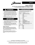
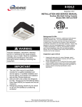
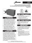
14-500.2
5H103442A1
January, 2014
INSTALLATION AND SERVICE MANUAL
Valedictorian Vertical Unit Ventilator
Models VFV, VFF, VSV, and VSF
TM
WARNING
Improper installation, adjustment, alteration,
service or maintenance can cause property
damage, injury or death, and could cause
exposure to substances which have been
determined by various state agencies to cause
cancer, birth defects or other reproductive harm.
Read the installation, operating and maintenance
instructions thoroughly before installing or
servicing this equipment.
IMPORTANT
1. The use of this manual is specifically intended
for a qualified installation and service agency.
A qualified installation and service agency must
perform all installation and service of these
appliances.
2. VFV, VFF, VSV and VSF units with DX
evaporator coils contain the refrigerant R-410A.
Review the R-410A Material Safety Data Sheet
(MSDS) for hazards and first aid measures.
3. Refrigerant charging should only be carried out
by an EPA-certified air conditioning contractor.
WARNING
This unit contains R-410A high pressure refrigerant.
Hazards exist that could result in personal injury
or death. Installation, maintenance, and service
must only be performed by an HVAC technician
qualified in R-410A refrigerant and using proper
tools and equipment. Due to much higher pressure
of R-410A refrigerant, DO NOT USE service
equipment or tools designed for refrigerants other
than R410A.
Inspection On Arrival
1. Inspect unit upon arrival. In case of damage, report it
immediately to transportation company and your local factory
sales representative.
2. C
heck rating plate on unit to verify that power supply meets
available electric power at the point of installation.
3. Inspect unit received for conformance with description of
product ordered (including specifications where applicable).
THIS MANUAL IS THE PROPERTY OF THE OWNER.
PLEASE BE SURE TO LEAVE IT WITH the owner WHEN YOU LEAVE THE JOB.
SPECIAL PRECAUTIONS
SPECIAL PRECAUTIONS
THE INSTALLATION AND MAINTENANCE INSTRUCTIONS
IN THIS MANUAL MUST BE FOLLOWED TO PROVIDE
SAFE, EFFICIENT, AND TROUBLE-FREE OPERATION. IN
ADDITION, PARTICULAR CARE MUST BE EXERCISED
REGARDING THE SPECIAL PRECAUTIONS LISTED BELOW.
FAILURE TO PROPERLY ADDRESS THESE CRITICAL
AREAS COULD RESULT IN PROPERTY DAMAGE OR LOSS,
PERSONAL INJURY, OR DEATH. THESE INSTRUCTIONS
ARE SUBJECT TO ANY MORE RESTRICTIVE LOCAL OR
NATIONAL CODES.
HAZARD INTENSITY LEVELS
1. DANGER: Indicates an imminently hazardous situation which,
if not avoided, WILL result in death or serious injury.
2. WARNING: Indicates a potentially hazardous situation which,
if not avoided, COULD result in death or serious injury.
3. CAUTION: Indicates a potentially hazardous situation which,
if not avoided, MAY result in minor or moderate injury.
4. IMPORTANT: Indicates a situation which, if not avoided, MAY
result in a potential safety concern.
DANGER
Appliances must not be installed where they may be exposed to
potentially explosive or flammable atmosphere.
WARNING
1. Disconnect power supply before making wiring
connections to prevent electrical shock and equipment
damage.
2. All appliances must be wired strictly in accordance with
the wiring diagram furnished with the appliance. Any
wiring different from the wiring diagram could result in a
hazard to persons and property.
3. Any original factory wiring that requires replacement must
be replaced with wiring material having a temperature
rating of at least 105°C.
4. Ensure that the supply voltage to the appliance, as
indicated on the serial plate, is not 5% greater than rated
voltage.
5. When servicing or repairing this equipment, use only
factory-approved service replacement parts. Refer to
the rating plate on the appliance for complete appliance
model number, serial number, and company address.
Any substitution of parts or controls not approved by the
factory will be at the owner’s risk.
2
CAUTION
1. Ensure that the supply voltage to the appliance, as
indicated on the serial plate, is not 5% less than the rated
voltage.
2. Units not approved for use in potable water systems.
3. Hot water supplied to the hot water heating option must
not exceed 200°F temperature or 125 PSIG pressure.
4. Do not operate the units within steam pressure greater
than 10 PSIG. Steam pressure must be 10 PSIG or lower
to avoid excessive discharge air temperatures that could
cause burns or personal injury.
5. Do not overcharge the refrigeration system. This can lead
to elevated compressor discharge pressure and possibly
flooding the compressor with liquid.
6. Do not attempt to reuse any mechanical or electrical
component which has been wet. Such component must
be replaced.
important
1. S
tart-up and adjustment procedures should be performed
by a qualified service agency.
2. N
o water-flow can cause a freeze condition resulting in
damage to the coil.
3. N
ever leave the unit filled with water in a building without
heat unless antifreeze has been added.
4. All refrigeration checks must be made by a qualified
R-410A refrigeration technician.
5. D
o not release refrigerant to the atmosphere. When
adding or removing refrigerant, all national, state/
province, and local laws must be followed.
6. To check most of the Possible Remedies in the
troubleshooting guide listed in Tables 23.1 & 24.1, refer to
the applicable sections of the manual.
Table of Contents
Inspection on Arrival . . . . . . . . . . . . . . . . . . . . . . . . . . . . . . . . . . . . 1
General Information . . . . . . . . . . . . . . . . . . . . . . . . . . . . . . . . . . . . . 1
Special Precautions . . . . . . . . . . . . . . . . . . . . . . . . . . . . . . . . . . . . . 2
Hazard Intensity Levels . . . . . . . . . . . . . . . . . . . . . . . . . . . . . . . . . . 2
SI (Metric) Conversion Factors . . . . . . . . . . . . . . . . . . . . . . . . . . . . 3
Unit Location . . . . . . . . . . . . . . . . . . . . . . . . . . . . . . . . . . . . . . . . . . 3
Handling . . . . . . . . . . . . . . . . . . . . . . . . . . . . . . . . . . . . . . . . . . 3
Preparation . . . . . . . . . . . . . . . . . . . . . . . . . . . . . . . . . . . . . . . . 3
Drainage . . . . . . . . . . . . . . . . . . . . . . . . . . . . . . . . . . . . . . . . . . 3
Electrical . . . . . . . . . . . . . . . . . . . . . . . . . . . . . . . . . . . . . . . . . . 3
Installation . . . . . . . . . . . . . . . . . . . . . . . . . . . . . . . . . . . . . . . . . . . . 3
Piping Installation . . . . . . . . . . . . . . . . . . . . . . . . . . . . . . . . . . . 4
Piping Insulation . . . . . . . . . . . . . . . . . . . . . . . . . . . . . . . . . . . . 5
Wiring . . . . . . . . . . . . . . . . . . . . . . . . . . . . . . . . . . . . . . . . . . . . 5
Terminal Strip Connections . . . . . . . . . . . . . . . . . . . . . . . . . . . . 5
Start-Up Procedure . . . . . . . . . . . . . . . . . . . . . . . . . . . . . . . . . . . . . 6
Pre-Start Checks . . . . . . . . . . . . . . . . . . . . . . . . . . . . . . . . . . . . 6
Unit Start-Up Procedure . . . . . . . . . . . . . . . . . . . . . . . . . . . . . . 6
Typical Sequence of Operation . . . . . . . . . . . . . . . . . . . . . . . 7-8
Start-Up Sheet - Example . . . . . . . . . . . . . . . . . . . . . . . . . . . . . 9-10
Dimensions . . . . . . . . . . . . . . . . . . . . . . . . . . . . . . . . . . . . . . . . 11-14
Piping Locations . . . . . . . . . . . . . . . . . . . . . . . . . . . . . . . . . . . 15-19
Technical Data . . . . . . . . . . . . . . . . . . . . . . . . . . . . . . . . . . . . . . . . 20
Component Layout . . . . . . . . . . . . . . . . . . . . . . . . . . . . . . . . . . . . 21
Maintenance . . . . . . . . . . . . . . . . . . . . . . . . . . . . . . . . . . . . . . . . . 22
Troubleshooting . . . . . . . . . . . . . . . . . . . . . . . . . . . . . . . . . . . . 23-24
Replacement Parts / Model Nomenclature . . . . . . . . . . . . . . . . . . 25
Serial Plate . . . . . . . . . . . . . . . . . . . . . . . . . . . . . . . . . . . . . . . . . . 26
Warranty . . . . . . . . . . . . . . . . . . . . . . . . . . . . . . . . . . . . . . . . . . . . 28
14.500.2
UNIT LOCATION
Table 3.1 - SI (Metric) Conversion Factors
To Convert Multiply By To Obtain
"W.C.
0.24
kPa
psig
6.893
kPa
°F (°F-32) x 0.555°C
inches
25.4
mm
feet
0.305 meters
CFM
0.028
m3/min
To Convert Multiply By To Obtain
CFH
1.699 m3/min
Btu/ft3 0.0374mJ/m3
pound
0.453
kg
Btu/hr 0.000293 kW/hr
gallons
3.785
liters
psig
27.7
"W.C.
unit location
DANGER
Units with cooling coils have a condensate drain pan connection
and 3/4" ID condensate line. The condensate drain pan
connection is field changeable and can be mounted on either
the left or right side of the unit. To change the connection
location, remove the condensate line from the elbow. Remove
the elbow from the drain pan and remove the plug from the
opposite side of the drain pan. Re-install the elbow and the plug
on the opposite sides of the drain pan. Switch the drain pan
mounting plates so that the shorter plate is on the same side as
the condensate line connection. Re-connect the condensate line.
A two inch diameter condensate drain hole is available on both
the left and right side of the back of the unit. The condensate
line must be connected to the main drain system in accordance
with any local codes and general good piping practice. For units
equipped with an optional condensate pump, the maximum lift is
15 feet (20 gph).
Appliances must not be installed where they may be exposed to
potentially explosive or flammable atmosphere.
Handling
Each unit will be shipped to the site secured to a wood skid
using metal brackets. Whenever possible, all lifting and handling
of the unit should be done with the packing and skid in position.
Due to the length of the unit, 72" forklift tines are recommended
to avoid damaging the unit.
Remove the metal brackets prior to lifting the unit off of the skid.
When slinging or using a forklift to lift the unit, the support points
should be sufficiently apart to give stability when lifting. Unless
otherwise noted the lifting points should be equidistant from the
centerline. Extreme care should be taken not to drop the unit.
Considerable damage can occur to the unit during positioning,
in particular, to the paneling and exterior paint. Use an adequate
number of personnel and the correct tools when moving the unit.
A lifting device such as a forklift is needed to install this product.
A special key is provided with the unit for use with the tamperproof cabinet locks on the top and front panels. The use of
torque screwdrivers on panel, cover or component mounting
screws is not recommended. Hand-start all screws. If electric
drills are used – set at the lowest possible torque.
Preparation
Drainage
1. Before installation, ensure that the correct electrical power
supplies are available for the unit.
2. Each unit requires an independently fused and isolated power
supply.
3. If the installation has multiple units, check that unit model
and tagging corresponds with the installation plans.
Please contact your Airedale representative immediately if
discrepancies are noted.
4. Check to make sure that the units will have adequate
installation clearance around them.
5. Note that units with cooling coils will have a condensate
connection at the rear and suitable provisions should be
made for draining. If multiple units tee into a common drain
manifold, it must be sized to ensure free draining with all the
units in operation.
6. For units with outside air, inspect the wall sleeve installation
for gaps that would allow leakage of outdoor air into the
space. All joints and abutments should be sealed with
waterproof sealant.
7. The cabinet must be secured to the back wall. The back of
the cabinet has four holes, two on each side. The type of
materials used for the walls will determine the type of fastener
to use. Use 3/8" diameter fasteners with 1-1/2" diameter
washers. Securing the cabinet to the wall helps to reduce
movement and noise due to vibration.
Electrical
Electrical wiring should be done in accordance with all
applicable national and local codes. It is the responsibility of the
electrical contractor to adhere to such codes. The warranty will
be voided if wiring is not in accordance with the specifications of
the unit. Use copper conductors only.
All power supply wiring must be capable of carrying the
maximum current load under no fault conditions at the stipulated
voltages. Care should be taken to avoid significant voltage
drops.
A knockout with strain relief is provided on the electrical box for
power wiring. Each unit is supplied with terminal strip for power
connection
INSTALLATION
The instructions detailed below are for the Installation of a
“Standard” unit. Accommodations and adjustments will be
required for the usage of additional unit accessories. Should
assistance be required for the installation of these additional
items, consult Modine at the phone number listed on the back
cover of this manual.
1. C
heck the walls and floor for straightness and check to
ensure that the wall is at a right angle to the floor Should
there be any irregularity, the placement of foam tape on the
outside edges of the unit will fill the gaps between the unit
and the wall, allowing for the use of a sealant, to create a
smooth transition from the unit to the wall.
2. R
emove the backing strip from the gasket on the wall sleeve.
Place the unit in the correct location, ensuring a tight seal with
the wall sleeve and the wall.
3. P
lace the unit in position and use the leveling legs to ensure
that the unit is level in both directions and also plumb.
Remove the front kick panel to access the leveling legs (see
Figure 4.1). Make sure that the foam gasket on the back of
the unit forms a tight seal between the unit and the wall.
4. After adjusting for any irregularity in the location site, locate
the position for the wall mounting bolts (see Figure 8.1).
The cabinet must be secured to the back wall. The back of
the cabinet has four holes, two on each side. The type of
materials used for the walls will determine the type of fastener
to use. Use 3/8" diameter fasteners with 1-1/2" diameter
washers. Securing the cabinet to the wall helps to reduce
movement and noise due to vibration. Drill the appropriate
sized holes, for the fasteners that are to be utilized, and insert
the anchors that are to be used.
5. M
ake the condensate drain connection and the electrical
connections to the unit.
14.500.2
3
START-UP PROCEDURE
Piping Installation - Chilled/Hot Water Coils
Figure 4.1 - Leveling Leg Location
CAUTION
1. U
nits not approved for use in potable water systems.
2. H
ot water supplied to the hot water heating option must
not exceed 200°F temperature or 125 PSIG pressure.
3. D
o not attempt to reuse any mechanical or electrical
component which has been wet. Such component must
be replaced.
1. Chilled water and hot water coils are supplied, from the
factory, with unions. Field installed piping can be mounted
to the supplied unions with 3/4" female sweat connections.
Factory assembled piping packages are supplied with
matching unions on the coil and the piping assembly.
2. Install shut-off valves in lines to and from each coil to allow
maintenance or replacement of unit without shutting down
and draining entire system (see Figures 4.2 and 4.3).
3. Include a circuit setter in the return line for water flow
regulation.
4. A drain valve (hose bib) should also be provided for each coil
to allow removal of water from the coil if located in an area
subject to freezing.
5. It is advisable to use a pipe line strainer before each coil.
6. Provide adequate pipe hangers, supports, or anchors to
secure the piping system independently of the coil.
Piping Installation – Direct Expansion (DX) Coils
CAUTION
1. Units with DX evaporator coils contain the refrigerant
R-410A. Review the R-410A Material Safety Data Sheet
(MSDS) for hazards and first aid measures.
2. Refrigerant charging should only be carried out by an
EPA-certified air conditioning contractor.
Figure 4.2 - Typical 2-Way Piping Installation
Note: R-410A refrigerant is the only approved refrigerant for this
system.
The unit should be piped up in accordance with good
refrigeration and/or plumbing practices.
The outdoor condensing unit must be connected to the indoor
unit coil using field supplied refrigerant grade (ACR) copper
tubing that is internally clean and dry. Units should be installed
only with the tubing sizes for the approved system combination
as specified in Table 20.1.
Condensing unit is typically factory charged for a 15-foot lineset.
For additional lineset lengths please refer to manufacturer’s
charging chart.
See the installation and maintenance manual provided with the
condensing unit for installation, evacuation and system charge
information.
4
Figure 4.3 - Typical 3-Way Piping Installation
14.500.2
INSTALLATION
Piping Installation - Steam Coils
Installation of wiring must conform with local building codes,
or in the absence of local codes, with the National Electric
Code ANSI/NFPA 70 - Latest Edition. Unit must be electrically
grounded in conformance to this code. In Canada, wiring must
comply with CSA C22.1, Part 1, Electrical Code.
CAUTION
Do not operate the units within steam pressure greater than
10 psig. Steam pressure must be 10 psig or lower to avoid
excessive discharge air temperatures that could cause
burns or personal injury.
Electric wiring must be sized to carry the full load amp draw of
the motor, starter and any controls that are used with the unit.
Refer to the unit serial plate for the unit specific electrical data.
1. Steam coils are supplied from the factory with 1" NPT
connections
2. A steam trap should be provided with a trap of sufficient size
and capacity to pass a minimum of two times the normal
condensate released by the unit at the minimum differential
pressure in the system.
Piping Insulation
Chilled water and condensate pipes should be insulated right
up to the coil to prevent condensation which can damage
objects located below the piping. Chilled water valves must also
be insulated to prevent sweating. Hot water pipes should be
insulated to reduce heat loss and to prevent overheating of the
end compartment.
Wiring
WARNING
1. Disconnect power supply before making wiring
connections to prevent electrical shock and equipment
damage.
2. All appliances must be wired strictly in accordance with
the wiring diagram furnished with the appliance. Any
wiring different from the wiring diagram could result in a
hazard to persons and property.
3. Any original factory wiring that requires replacement must
be replaced with wiring material having a temperature
rating of at least 105°C.
4. Ensure that the supply voltage to the appliance, as
indicated on the serial plate, is not 5% greater than rated
voltage.
Any damage to or failure of units caused by incorrect wiring of
the units is not covered by warranty.
Once the piping installation is complete, the electrical supply can
be connected to the terminal strip in the electrical box.
When installing any wiring into the control box, extra cable must
be left outside the panel to allow the panel to open fully. Failure
to follow these instructions may cause damage to the wiring
and/or the unit.
Terminal Strip Connections
The terminal strip connections are designed to clamp down on
the wires. To properly connect the wires to the terminal strip:
1. P
ush a small flat-head screwdriver into the square hole on the
terminal. Press firmly until the screwdriver hits the back stop
and opens the terminal (see Figure 5.1).
2. R
emove approximately 3/8" of insulation from the end of
the wire and push the stripped wire into the oval hole in the
terminal.
3. R
emove the screwdriver. Pull on the wire to make sure that it
is securely clamped in the terminal.
4. M
ake sure that the terminal clamp is in contact with bare wire
(insulation removed).
Figure 5.1 - Terminal Strip
CAUTION
1. Ensure that the supply voltage to the appliance, as
indicated on the serial plate, is not 5% less than the rated
voltage.
2. Do not attempt to reuse any mechanical or electrical
component which has been wet. Such component must
be replaced.
14.500.2
5
start-up procedure
start-uP procedure
important
1. Start-up and adjustment procedures should be performed
by a qualified service agency.
2. No water-flow can cause a freeze condition resulting in
damage to the coil.
3. Never leave the unit filled with water in a building without
heat unless antifreeze has been added.
See start-up sheet examples - Figures 9.1 and 10.1.
Pre-Start Checks
1.Check that the supply voltage matches the unit supply
voltage listed on the Unit Serial Plate. Verify that all wiring is
secure and properly protected. Trace circuits to insure that
the unit has been wired according to the wiring diagram.
2. Check that the unit has no visible damage and that all the
components are secure.
3. Check that all field electrical and mechanical work has been
performed according to all applicable Federal, State, and
Local codes.
4. Check the supply voltage to the unit is within +/- 5% of the
voltage on the unit serial plate.
5. Check that the system has been correctly flushed.
6. Check for any water leaks.
7. The unit and interconnecting piping have been evacuated
correctly and the condensing unit service valves are open
(DX Cooling units only).
8. Check that the plug is installed for the condensate
connection that is not being used.
9. Check that the motor is secure and the shaft and blower set
screws are tight. Rotate the blower shaft by hand.
10. Check that the filters have been properly installed.
9.During the unit operation, measure and record all the
information that is required to complete the Start-Up Sheets
that are supplied with the unit. Copy the information onto the
Start-Up Sheets (Figures 9.1 and 10.1) in this manual for
your records.
10. (DX
Cooling models only) Shut unit down and disconnect
the main power. The compressor signal Y1 (disconnected
from the indoor unit in step 2) can now be re-connected and
main power applied to the system.
Note: (DX Cooling models only) The 24V power for the indoor
unit control circuit is supplied from a unit factory-installed
transformer. When the indoor and outdoor units are supplied
from separate main supplies, care must be taken to ensure that
the outdoor unit is isolated whenever the indoor unit power is
removed. Failure to do so may result in freeze ups and other
damage to the unit.
Unit Start-Up Procedure
Note: For models with DX Cooling, see the installation and
maintenance manual provided with the condensing unit for startup information.
1.(DX Cooling models only) Ensure that the condensing unit
start-up procedure has been carried out, as detailed in the
condensing unit installation and maintenance manual.
2.(DX Cooling models only) The compressor should be
isolated by removing the connection at the Y1 terminal
on the indoor unit. Main power can now be applied to the
indoor and outdoor units. A system electrical check can now
be carried out.
3. Switch the 3-speed switch to position 1, 2 or 3.
4. Switch the disconnect switch to the “ON” position.
5.Confirm that the blower motor is rotating in the correct
direction and blowing air out of the supply air grill.
6. (Units with Chilled Water, Hot Water and Steam coils only)
Ensure all valves are open to the unit.
7.(Units with Chilled Water and Hot Water only) Check water
flow rates and pressure drops and compare to design.
8.Check that the dampers are not obstructed and move
through their full range of motion.
6
14.500.2
START-UP PROCEDURE
Hot Water or Steam with Valve Control
Typical Sequence of Operation
Supply Fan
The supply fan shall run at all times when unit is in occupied
mode. When in unoccupied mode, the supply fan shall run only
on a call for heating or cooling. The supply fan speed can be
adjusted using the standard equipped manual 3-speed switch.
If equipped with Modine Control System, the supply fan is
programmed to run for 2 minutes (adjustable) after the heating
or cooling cycle ends.
Freeze Stat (Optional)
On units equipped, an adjustable auto-resetting freeze stat is
factory set to trip at 35˚F. If the coil temperature reaches the
limit and the freeze stat trips, it shall automatically reset when
the coil temperature rises 5˚F above the setpoint. The freeze
stat shall be wired so that upon tripping, power is removed from
the supply fan, the outside air damper closes, and either the
HW valve opens (model digit 3=V) or the face & bypass damper
goes to full bypass (model digit 3=F)..
Outside Air and Return Air Dampers (Optional)
The outside air and return air dampers control the mixture of
return air and outside air drawn through the unit. Both dampers
are linked together and are controlled by an actuator requiring a
2-6VDC proportional signal. At 2V, the dampers are positioned
for full return air and no outside air. At 6V, the dampers are
positioned for full outside air and no return air. The outside air
damper shall open to a minimum position to provide ventilation
requirements when the room is occupied. When in heating
mode, if the space temperature is more than 4˚F from the
heating setpoint, the outside air damper shall fully close. The
outside air damper shall also be fully closed during unoccupied
mode. If the unit is equipped with a CO2 sensor, the outside air
damper shall modulate open proportionally to compensate for
the CO2 levels in the room.
The dampers can act as economizers for free-cooling. If
cooling is required and the outside air temperature is below
the economizer outside air lockout temperature (60˚F
recommended) and above 35˚F (adjustable), the outside air
damper shall modulate open. On units with a Carel controller,
the outside air damper shall fully open when the room
temperature is above the setpoint by more than 1˚F (adjustable).
Within 1˚F, the proportional band adjusts the outside air damper.
When the unit is in free-cooling, water valves shall be fully
closed, and if equipped, the face & bypass damper should move
to full bypass position. The outside air lockout temperature on
Carel units is factory set to 60˚F and is adjustable.
Chilled Water with Valve Control
Units with a chilled water coil and non-Carel controls desiring
valve control shall use a non-spring return modulating valve
operated by either a proportional (2-10VDC) or a tri-state
(24VAC) signal. Units with a chilled water coil and Carel controls
desiring valve control shall use a modulating valve requiring a
tri-state signal. When the room temperature is above the cooling
setpoint, the valve shall open proportionally according to the
adjustable proportional band. The adjustable proportional band
on the Carel controller is set to a default 1˚F (example: valve is
50% open when room temperature is 0.5˚F from setpoint). The
Carel controller will not allow the chilled water valve to open
when the outside air temperature is below 55˚F.
Units with a hot water or steam coil and non-Carel controls
desiring valve control shall use a spring-return, normally open
modulating valve operated by a proportional signal (2-10VDC)
or a tri-state (24VAC) signal. Units with Carel controls desiring
valve control shall use a modulating control valve with a
proportional signal. When the room temperature is below the
heating setpoint, the valve shall open proportionally according
to the adjustable proportional band. The adjustable proportional
band on the Carel controller is set to a default 1˚F (example:
valve is 50% open when room temperature is 0.5˚F from
setpoint). If for any reason the supply air temperature drops
below 55˚F (adjustable), the valve shall modulate open to
maintain 55˚F.
Direct Expansion (DX) Cooling Control
When the room temperature is above the cooling setpoint, the
compressor will be energized. The compressor will de-energize
when the room temperature falls below the cooling setpoint.
If the factory installed low limit stat detects indoor evaporator
coil temperatures below its set point, the compressor will be
disabled.
Chilled Water with Face & Bypass Control
Units equipped with a chilled water coil and face & bypass
control shall modulate the face & bypass damper via a spring
return actuator, controlled by a proportional signal (2-5.5V).
The face & bypass damper regulates the amount of return
air and outside air passing through the chilled water coil. On
a call for cooling, the damper shall open to the face of the
coil proportionally based on how many degrees the room
temperature is from the setpoint. The adjustable proportional
band on the Carel controller is set to a default 1˚F (example:
damper is 50% open when room temperature is 0.5˚F from
setpoint). When the damper is in full bypass position (2V), all
return and outside air bypasses the chilled water coil. When the
damper is in full face position (5.5V), all return and outside air
passes through the chilled water coil.
Hot Water with Face & Bypass Control
Units equipped with a hot water or steam coil and face & bypass
control shall modulate the face & bypass damper via a spring
return actuator, controlled by a proportional signal (2-5.5V).
The face & bypass damper regulates the amount of return air
and outside air passing through the heating coil. On a call for
heating, the damper shall open proportionally based on how
many degrees the room temperature is from the setpoint. The
adjustable proportional band on the Carel controller is set
to a default 1˚F (example: damper is 50% open when room
temperature is 0.5˚F from setpoint). When the damper is in full
bypass position (2V), all return and outside air bypasses the
heating coil. When the damper is in full face position (5.5V),
all return and outside air passes through the heating coil. If
for any reason the supply air temperature drops below 55˚F
(adjustable), the heating valve shall open (if equipped) and the
face and bypass damper shall modulate to maintain 55˚F.
Hot Water and Chilled Water (2-Pipe) with Valve
Control
Units desiring valve control to provide heating and cooling
on a single water coil (2-pipe system) and not using Carel
controls shall use a spring-return, normally open modulating
valve operated by a proportional signal (2-10VDC) or a tristate (24VAC) signal. Units with Carel controls shall use a
modulating control valve with a proportional signal. On a call
for heating or cooling (depending on the season), the valve
14.500.2
7
sequence of operation
shall open proportionally based on how many degrees the room
temperature is from the setpoint. The adjustable proportional
band on the Carel controller is set to a default 1˚F (example:
valve is 50% open when room temperature is 0.5˚F from
setpoint). If for any reason the supply air temperature drops
below 55˚F (adjustable), the water valve shall modulate open to
maintain 55˚F. On 2-pipe units not having Carel controls or not
connected to a network, an optional aquastat is recommended
to prevent inadvertent changeover of heating/cooling modes.
Hot Water and Chilled Water (2-Pipe) with
Face & Bypass Control
Units desiring face and bypass control to provide heating
and cooling on a single water coil (2-pipe system) shall
modulate the face & bypass damper via a spring return
actuator, controlled by a proportional signal (2-5.5V). The
face & bypass damper regulates the amount of return air
and outside air passing through the water coil. On a call for
heating or cooling (depending on the season), the damper shall
open proportionally based on how many degrees the room
temperature is from the setpoint. The adjustable proportional
band on the Carel controller is set to a default 1˚F (example:
damper is 50% open when room temperature is 0.5˚F from
setpoint). When the damper is in full bypass position (2V),
all return and outside air bypasses the water coil. When the
damper is in full face position (5.5V), all return and outside air
passes through the water coil. If for any reason the supply air
temperature drops below 55˚F (adjustable), the water valve
shall open (if equipped) and the face and bypass damper shall
modulate to maintain 55˚F.
2-Position Control Valves
Optional spring-return, 2-position control valves can be used to
control the end of cycle flow on both chilled and hot water coils.
On a chilled water coil, a normally closed valve is used. On a
hot water coil or 2-pipe changeover system, a normally open
valve is used.
The 2-position valve used on a chilled water coil shall open on a
call for cooling when the outside air temperature is greater than
55˚F (adjustable). When the outside air temperature is less than
55˚F, the valve should remain closed and free cooling shall be
utilized. The 2-position chilled water valve shall be closed when
the 2-position hot water valve is open (when equipped). The
valve is controlled by a 24VAC digital output.
Condensate Pump (Optional)
On units equipped with a condensate pump, the pump shall
begin to run once the condensate reaches a set level. The
pump comes with an internal safety switch that can be wired
either normally open or normally closed. The safety switch shall
be wired such that the chilled water valve closes when it trips.
On Carel units, the switch shall be wired normally closed into
a digital input of the controller. If the unit is also equipped with
a condensate pan float switch, both switches shall be wired in
series.
Condensate Pan Float Switch (Optional)
On units equipped with a condensate pan float switch, the
normally closed switch shall be wired such that the chilled
water valve closes or the outdoor condensing unit is disabled
(DX Cooling Models Only) upon tripping. On Carel units, the
switch shall be wired normally closed into a digital input of the
controller. If the unit is also equipped with a condensate pump,
both the condensate pump limit switch and condensate pan float
switch shall be wired in series.
CO2 Sensor (Optional)
An optional CO2 sensor with a range of 0-2000 ppm producing
an output signal of 4-20mA is available to modulate the outside
air damper. If equipped, the outside air damper shall modulate
open proportionally to compensate for the CO2 levels in the
room. On Carel units, if the CO2 level is 800 ppm or less
(adjustable), the damper shall remain at its normal minimum
position. If the CO2 level increases above 800 ppm, the
damper begins to open according to the proportional band.
The proportional band is set to a default of 200 ppm and is
adjustable. Using the default, once the CO2 level reaches 1000
ppm, the damper shall be at its maximum ventilation position.
Fire Detector (Optional)
Units equipped with an optional fire detector shall shut down
power to the supply fan and close all dampers upon the
detection of a fire.
Smoke Detector (Optional)
Units equipped with an optional smoke detector shall shut
down power to the supply fan and close all dampers upon the
detection of smoke. The LED on the smoke detector will stay on
solid. Cycle the power Off and then On to reset.
The 2-position valve used on a hot water coil shall open on a
call for heating. The valve shall always open when the outside
air temperature drops below 40˚F. This is to prevent the coil
from freezing or nuisance tripping of the freeze stat. The
2-position hot water valve shall be closed when the 2-position
chilled water valve is open (if equipped). The valve is controlled
by a 24VAC digital output.
The 2-position valve used on a 2-pipe changeover system shall
operate like the 2-position chilled water valve in cooling mode,
and like the 2-position hot water valve in heating mode.
8
14.500.2
start-up sheet - example
Figure 9.1 - Start-Up Sheet - EXAMPLE Page 1
14.500.2
9
start-up sheet - example
Figure 10.1 - Start-Up Sheet - EXAMPLE Page 2
10
14.500.2
dimensions - 16-5/8" DEPTH - FLAT TOP UNIT
Figure 11.1 - Dimensions - 16-5/8" Depth - Flat Top Unit
Table 11.1 - Unit Width Dimensions
Model Size
750
Dimensions (inches)
W1
W2
W3
62
36
30
1000
74
48
42
1250
86
60
54
1500
98
72
66
14.500.2
11
dimensions - 21-7/8" DEPTH - FLAT TOP UNIT
Figure 12.1 - Dimensions - 21-7/8" Depth - Flat Top Unit
Table 12.1 - Unit Width Dimensions
Model Size
750
12
Dimensions (inches)
W1
W2
W3
62
36
30
1000
74
48
42
1250
86
60
54
1500
98
72
66
14.500.2
dimensions - 16-5/8" DEPTH - slope TOP UNIT
Figure 13.1 - Dimensions - 16-5/8" Depth - Slope Top Unit
Table 13.1 - Unit Width Dimensions
Model Size
Dimensions (inches)
W1
W2
W3
750
62
36
30
1000
74
48
42
1250
86
60
54
1500
98
72
66
14.500.2
13
dimensions - 21-7/8" DEPTH - slope TOP UNIT
Figure 14.1 - Dimensions - 21-7/8" Depth - Slope Top Unit
Table 14.1 - Unit Width Dimensions
Model Size
14
Dimensions (inches)
W1
W2
W3
750
62
36
30
1000
74
48
42
1250
86
60
54
1500
98
72
66
14.500.2
PIPING LOCATIONS
Figure 15.1 - Chilled Water Coil with Optional Reheat Piping Locations
Chilled Water Coil Only, 2-Pipe Chilled Water/Hot Water Coil, or Chilled Water Coil with Reheat Coil
Table 15.1 - Chilled Water Coil with Optional Reheat Piping Locations ➀
Unit Depth
16 5/8
21 7/8
Coil Rows
2-Row
3-Row
4-Row
2-Row
3-Row
4-Row
A
14.25
15.00
15.00
14.25
15.00
15.00
B
11.25
11.00
11.00
16.50
16.25
16.25
Dimensions (inches)
D
E
4.75
13.50
4.75
13.50
4.75
14.00
10.00
13.50
10.00
13.50
10.00
14.00
C
7.25
7.50
7.50
7.25
7.50
7.50
F
12.25
12.00
11.75
17.50
17.25
17.00
G
8.25
8.75
9.50
8.25
8.75
9.50
H
4.00
3.50
3.00
10.00
8.75
8.25
F
9.50
10.00
10.00
14.75
15.25
15.25
G
11.50
11.25
11.25
11.50
11.25
11.25
H
1.50
1.50
1.50
6.75
6.75
6.75
➀ For Hot Water Reheat piping location see Figure 18.2. For Steam Reheat Piping location see Figure 19.2.
Figure 15.2 - Chilled Water Coil with Pre-Heat Piping Locations
Chilled Water Coil with Pre-Heat Coil Only
Table 15.2 - Chilled Water Coil with Pre-Heat Piping Locations ➀
Unit Depth
16 5/8
21 7/8
Coil Rows
2-Row
3-Row
4-Row
2-Row
3-Row
4-Row
A
17.50
17.50
16.75
17.50
17.50
16.75
B
8.75
8.75
9.25
14.00
14.00
14.50
C
10.50
10.00
9.25
10.50
10.00
9.25
Dimensions (inches)
D
E
2.25
16.50
2.75
16.00
3.25
16.00
7.50
16.50
8.00
16.00
8.50
16.00
➀ For Hot Water Pre-Heat piping location see Figure 18.1. For Steam Pre-Heat Piping location see Figure 19.1.
14.500.2
15
PIPING LOCATIONS
Figure 16.1 - DX Cooling (Size 750 Only) with Optional Reheat Piping Locations
Size 750 DX Cooling Coil Only or DX Cooling Coil with Reheat Coil
Table 16.1 - DX Cooling Coil Piping Locations ➀
Unit Depth
Model Size
16 5/8
21 7/8
750
750
A
14.25
14.25
Dimensions (inches)
B
C
11.25
7.25
16.50
7.25
D
4.75
10.00
➀ For Hot Water Reheat piping location see Figure 18.2. For Steam Reheat piping location see Figure 19.2.
Figure 16.2 - DX Cooling (Size 750 Only) with Pre-Heat Piping Locations
Size 750 DX Cooling Coil with Pre-Heat Coil Only
Table 16.2 - DX Coil with Pre-Heat Piping Locations ➀
Unit Depth
Model Size
16 5/8
21 7/8
750
750
A
14.25
14.25
Dimensions (inches)
B
C
11.25
7.25
16.50
7.25
D
4.75
10.00
➀ For Hot Water Pre-Heat piping location see Figure 18.1. For Steam Pre-Heat piping location see Figure 19.1.
16
14.500.2
PIPING LOCATIONS
Figure 17.1 - DX Cooling with Optional Reheat Piping Locations
Size 1000, 1250, 1500 DX Cooling Coil Only or DX Cooling Coil with Reheat Coil
Table 17.1 - DX Cooling Coil Piping Locations ➀
Unit Depth
Model Size
16 5/8
21 7/8
1000, 1250, 1500
1000, 1250, 1500
A
7.50
12.75
Dimensions (inches)
B
C
4.50
11.75
9.75
17.00
D
10.50
15.75
➀ For Hot Water Reheat piping location see Figure 18.2. For Steam Reheat piping location see Figure 19.2.
Figure 17.2 - DX Cooling with Pre-Heat Piping Locations
Size 1000, 1250, 1500 DX Cooling Coil with Pre-Heat Coil Only
Table 17.2 - DX Coil with Pre-Heat Piping Locations ➀
Unit Depth
Model Size
16 5/8
21 7/8
1000, 1250, 1500
1000, 1250, 1500
A
4.50
9.75
Dimensions (inches)
B
C
1.75
8.75
7.00
14.00
D
7.75
13.00
➀ For Hot Water Pre-Heat piping location see Figure 18.1. For Steam Pre-Heat piping location see Figure 19.1.
14.500.2
17
Piping locations
Figure 18.1 - Hot Water Heating Coil Piping Locations
Hot Water Heating Coil Only or Chilled Water/DX Cooling Coil with Hot Water Pre-Heat Coil
Table 18.1 - Hot Water Heating Coil Piping Locations ➀
Unit Depth
16 5/8
21 7/8
Coil Rows
1-Row
2-Row
1-Row
2-Row
A
14.25
14.25
14.25
14.25
B
11.50
11.25
16.75
16.50
C
7.00
7.25
7.00
7.25
Dimensions (inches)
D
E
5.00
13.50
4.75
13.50
10.25
13.50
10.00
13.50
F
12.00
12.25
17.25
17.50
G
8.25
8.25
8.25
8.25
H
4.00
4.00
9.25
9.25
F
9.50
9.50
14.75
14.75
G
11.50
11.50
11.50
11.50
H
1.25
1.50
6.50
6.75
➀ For Chilled Water piping location see Figure 15.2. For DX Cooling piping location see Figures 16.2 and 17.2.
Figure 18.2 - Hot Water Reheat Coil Piping Locations
Chilled Water/DX Cooling Coil with Hot Water Reheat Coil Only
Table 18.2 - Hot Water Reheat Coil Piping Locations ➀
Unit Depth
16 5/8
21 7/8
Coil Rows
1-Row
2-Row
1-Row
2-Row
A
17.50
17.50
17.50
17.50
B
8.75
8.75
14.00
14.00
C
10.25
10.50
10.25
10.50
Dimensions (inches)
D
E
2.25
16.75
2.25
16.50
7.50
16.75
7.50
16.50
➀ For Chilled Water piping location see Figure 15.1. For DX Cooling piping location see Figures 16.1 and 17.1.
18
14.500.2
PIPING LOCATIONS
Figure 19.1 - Steam Heating Coil Piping Locations
Steam Heating Coil Only or Chilled Water/DX Cooling Coil with Steam Pre-Heat Coil
Table 19.1 - Steam Heating Coil Piping Locations ➀
Unit Depth
Coil Rows
16 5/8
21 7/8
1-Row
1-Row
Dimensions (inches)
A
B
12.25
4.00
17.50
9.25
➀ For Chilled Water piping location see Figure 15.2. For DX Cooling piping location see Figures 16.2 and 17.2.
Figure 19.2 - Steam Reheat Coil Piping Locations
Chilled Water/DX Cooling Coil with Steam Reheat Coil Only
Table 19.2 - Steam Reheat Coil Piping Locations ➀
Unit Depth
Coil Rows
16 5/8
21 7/8
1-Row
1-Row
Dimensions (inches)
A
B
9.50
1.25
14.75
6.50
➀ For Chilled Water piping location see Figure 15.1. For DX Cooling piping location see Figures 16.1 and 17.1.
14.500.2
19
technical data
Table 20.1 - Technical Data
VFF, VSF, VFV, & VSV
Units
SUPPLY FAN
750
Fan Quantity
1000
2
Fan Diameter
3
8.06
Fan Width
Motor Size (Qty 1)
hp
Airflow (High/Medium/Low)
Max External Static Pressure
Motor Size (Qty 1)
Max External Static Pressure
1 Row
3 Row
Inches
Steam Coil
Inches
Evaporator Coil
0.76
1.17
1.42
Shipping Weight – 16 5/8” Units
Operating Weight – 21 7/8” Units
375
in.
10 X 36
470
365
425
370
Quantity
420
320
lbs.
Dimensions
1.28
1.66
1” NPT
lbs.
FILTER
1.1
3/4" ID condensate line
lbs.
Shipping Weight – 21 7/8” Units
0.5
0.88
3/4” OD Suction, 1/2” OD Liquid
lbs.
Operating Weight – 16 5/8” Units
0.25
Unions with 3/4” female solder joint
Inches
UNIT WEIGHT (approximate)
1/4
0.44
0.63
0.91
Inches
Condensate Line
0.05
1500/1250/1000
0.25
0.38
0.92
Water Coils
1/4
1250/1100/1000
0.25
0.72
gal
CONNECTIONS
1/4
0.51
gal
4 Row
1/2
1500/1100/900
0.05
1000/850/750
0.32
gal
1/2
1250/900/750
0.05
0.25
gal
2 Row
7.15
ECM - Electonically Commutated Motor
750/650/550
in.Wg
COIL WATER VOLUME
1/2
1/4
cfm
7.15
1000/750/600
0.05
hp
Airflow (High/Medium/Low)
8.06
PSC with Thermal Overload Protection
750/650/500
in.Wg
Motor Type (Premium High Static)
4
8.06
7.15
1/2
cfm
1500
4
8.06
7.15
Motor Type (Standard
1250
Direct Drive Centrifugal
520
410
480
450
540
425
600
480
530
1" Woven Fiberglass, 70-75% Arrestance
1
2
2
10 X 24
2
10 X 30
10 X 36
Table 20.2 - Electrical Data
Motor Size
FLA
1/2 HP ECM Blower (Upgrade)
7.7
1/4 HP Blower (Std)
115V
2.7
1/4 HP Blower, Condensate Pump
1/2 HP ECM Blower, Condensate Pump
MCA
MOP
FLA
9.6
15.0
5.0
11.1
15.0
3.4
4.2
4.9
9.2
6.0
6.0
1.5
2.1
5.6
208V
MCA
MOP
FLA
6.3
10.0
4.3
6.9
10.0
1.9
2.5
3.0
1.4
4.0
1.9
4.8
230V
MCA
MOP
FLA
5.4
8.0
4.1
1.7
2.2
5.9
3.0
3.0
10.0
277V
1.1
MCA
MOP
5.1
6.0
1.4
1.6
1.9
4.6
5.6
2.0
3.0
6.0
Table 20.3 - Sound Data
Model
Speed
CFM
dBA
L
500
55.7
750
M
650
62.8
H
750
66.5
L
600
56.2
1000
M
750
61.5
H
1000
68.4
L
750
57
1250
M
900
61.4
H
1250
69.8
L
900
61.3
Notes:
1. Rated in accordance with ARI Standard 350-2008.
2. Sound power levels were recorded using ARI standard 220-2007 method.
3. Sound power levels were recorded with the unit running in full recirculation mode with standard PSC Motor (Digit 16=1) and a 3 row coil.
20
14.500.2
1500
M
1100
66.1
H
1500
73.3
component layout
Figure 21.1 - Exploded View
Figure 21.2 - Component Layout
Control
Panel
Blower
Motor
Freeze Stat
(Optional)
Face &
Bypass
Damper
Actuator
(Optional)
Field
Installed
Piping
Outside Air/Return Air
Damper Actuator
(Optional)
Face & Bypass
Damper
(Optional)
Filters
14.500.2
Blowers
Electrical Box with Power
Connection, Disconnect Switch and
3-Speed Fan Switch
21
maintenance
MAINTENANCE
Access
Access to the unit is gained by opening the front panels and
hinged top side covers using the key that is provided.
WARNING
When servicing or repairing this equipment, use only factoryapproved service replacement parts. A complete replacement
parts list may be obtained by contacting Modine Manufacturing
Company. Refer to the rating plate on the appliance for
complete appliance model number, serial number, and
company address. Any substitution of parts or controls not
approved by the factory will be at the owner’s risk.
CAUTION
With the Disconnect in the “OFF” position: check the filter(s)
and replace if necessary. Slide the filter(s) out of the track
and replace with new filter(s). See Figure 22.1. The filters are
positioned under the coil assembly. Never run the unit without
filters.
(Before the heating and cooling season)
important
To check most of the possible remedies in the troubleshooting
guide listed in Tables 23.1 & 24.1, refer to the applicable
sections of the manual.
The routine care and maintenance of this unit will increase
longevity, provide for the proper operational performance, and
reduce the probability of failure.
Once the unit is operational, it will be necessary to perform
certain routine maintenance/service checks. Following is a
Maintenance Schedule with the recommended checks. If your
unit is equipped with special features, there may be additional
checks that are required. Consult Modine for assistance.
The use of torque screwdrivers on panel, cover or component
mounting screws is not recommended. Hand-start all screws. If
electric drills are used – set at the lowest possible torque.
22
Every ONE (1) MONTH
Every SIX (6) MONTHS
Do not attempt to reuse any mechanical or electrical
controllers which have been wet. Replace defective
controller.
Figure 22.1 - Filter Location
Maintenance Schedule
1. C
heck for correct fan operation, no excessive noise or
vibrations.
With the Disconnect Switch in the “OFF” position:
2. Inspect all electrical circuits including optional components
and sensors for loose connections and signs of overheating,
arcing, chafing or other physical damage. The electrical
control section should also be wiped clean of all dirt that may
affect the unit operation.
3. C
heck the filter(s) and replace if necessary. Slide the filter(s)
out of the track and replace with new filter(s) (see Figure 22.1).
The filters are positioned under the coil assembly. Never run
the unit without filters.
4. C
heck the control wiring and sensors. Check the operation
and sequencing of controls and ensure that all relevant set
points are recorded.
5. C
heck all warning labels to ensure they can be read and that
they have not been removed.
6. Inspect condensate hose for any possible clogs.
7. C
heck for general obstructions to inlet and discharge
openings.
8. O
il the fan motor by adding 3 drops of SAE 20 weight nondetergent oil to the two oil holes on the fan motor.
9. F
ill the fan shaft bearing cup with oil. The fan shaft bearing
is located in the housing at the opposite end of the fan shaft
from the motor (see Figure 22.2). Additional bearing cup in
middle of unit on 1250 and 1500 CFM units and is accessible
through the front panel.
Figure 22.2 - End Shaft Bearing Cup Location
14.500.2
troubleshooting
Table 23.1 - Troubleshooting - General
Trouble
A. Unit Not Operating Power On
B. Unit Operating No Mechanical
Heating / Cooling
C. No Indoor Fan
D. Hot Water / Chilled
Water Valve Not
Operational (Option)
E. D
X Split Units Only:
Low Suction Pressure
(LP Switch Tripped)
Possible Cause
Possible Remedy
1. Unit mounted disconnect in the “OFF” position.
1. Turn the disconnect switch to the “ON” position.
2. Unit mounted 3-speed selector switch in the
“0” position.
2. Turn the 3-speed selector switch to the “1, 2, or 3” position.
3. Unit switched OFF in the microprocessor.
3. Consult microprocessor documentation.
4. Delay on start set incorrectly.
4. Consult microprocessor documentation.
5. Unit not in occupied mode.
5. Consult microprocessor documentation, and consult
microprocessor occupied setpoints.
6. Fire/smoke alarm tripped.
6. De-energize and re-energize unit.
7. Tripped circuit breakers.
7. Reset the tripped circuit breaker(s).
8. Loose mains or control wiring.
8. With power OFF from distribution panel inspect the field
wiring connections in the electrical panel.
9. Occupancy sensor malfunction.
9. Inspect connections beginning with sensor input from the
microprocessor.
10. Hot water freeze protection (optional) stat
tripped.
10. Manually reset at stat.
1. Heating/cooling not required.
1. Verify applicable set point with return air temperature.
2. No output from microprocessor.
2. Consult microprocessor documentation.
3. DX Split Units Only: HP/LP pressure safety
switch(es) tripped (open).
3. Inspect high and low system pressures and wiring.
Check for dirty filters in Heat Pump mode.
4. DX Split Units Only: Internal overload switch
on compressor tripped (open).
4. Wait for compressor motor windings to cool down
(This switch is automatic reset).
5. Loose control wiring connections.
5. Inspect connections beginning with compressor output
from the microprocessor.
6. Tripped circuit breakers.
6. Reset the tripped circuit breaker(s).
7. Low temperature unit lockout.
7. Consult microprocessor setpoints. 8. DX Split Units Only: Compressor faulty.
8. Replace compressor.
9. Condensate pan/pump float switch tripped.
9. Check condensate pan/pump and piping for blockage.
1. Motor tripped on internal overload.
1. Let motor cool down and reset - possible bad motor or
blocked filter.
2. Fan not required
2. Consult microprocessor documentation, or set thermostat
to “ON”. Check if unit is in unoccupied and standby mode.
3. No power to the fan.
3. Check to make sure plugs are locked in place and all pins
are secure. Check for 24V control signal.
4. Current sensor fault.
4. Make sure sensor is functioning correctly.
1. Heating not required.
1. Consult microprocessor documentation.
2. Loose wiring connections.
2.Inspect connections beginning with valve output from the
microprocessor. Check to ensure 24V supply power is
present at actuator.
3. Faulty heating actuator.
3. Replace actuator if faulty.
4. Isolation valves are open.
4. Check for additional external isolation valves.
5. Check for DC control signal.
5. Check for 2-10vDC signal from microprocessor.
1. Low refrigeration charge.
1. Measure unit operating pressures. Add charge and check
for leaks.
2. Clogged filter(s).
2. Replace filter(s) as necessary.
3. Clogged liquid line filter drier.
3. Replace drier with a direct replacement. Follow proper
procedure.
4. Improper expansion valve setting or valve
malfunctioning.
4. Check operation and superheat settings.
5. Low/restricted supply airflow.
5. Check diffusers, filters and supply motor to ensure
appropriate airflow.
14.500.2
23
troubleshooting
Table 24.1 - Troubleshooting - General
Trouble
F. D
X Split Units Only:
Low Discharge
Pressure
G. D
X Split Units Only:
High Suction Pressure
H. DX Split Units Only:
High Discharge
Pressure
I. Condensate Leaking
J. Microprocessor Not
Working - Faulty
Operation
24
Possible Cause
Possible Remedy
1. Low refrigeration charge.
1. Measure unit operating pressures. Add charge and check
for leaks.
2. Faulty compressor.
2. Replace compressor.
3. Faulty reversing valve.
3. Evacuate system and replace reversing valve.
4. Outdoor air sensor out of calibration.
4. Check outdoor air sensor for accuracy.
1. Excessive load.
1. Check occupancy of space.
2. Expansion valve malfunctioning (overfeeding).
2. Check remote bulb is secure and vapor sealed, and
regulate superheat.
3. Faulty compressor.
3. Replace compressor.
1. Improper installation of wall sleeve and louver.
1. Ensure splitter plate is in contact with the back of the louver
blade and the unit to ensure no re-circulation of exhaust air
takes place.
2. Dirty condenser coils.
2. Clean condenser coil.
3. System overcharged.
3. Remove excess refrigerant.
4. Noncondensables in system.
4. Evacuate refrigerant circuit and recharge.
5. Condenser fan speed is too slow (cooling
mode).
5. Not applicable, refer to manufacturer's Technical Manual.
1. Condensate drain not piped up.
1. Pipe condensate drain.
2. Condensate pan/line plugged.
2. Clean drain pan and piping.
3. Condensate pump (optional) faulty.
3. Check operation of condensate pump. Replace pump if
necessary.
1. Loose sensor wire connectors.
1. Inspect sensor connections at the microprocessor.
2. Strategy file corrupted.
2. Consult microprocessor documentation.
3. Loose control wiring.
3. Check 24V power supply wiring.
14.500.2
replacement parts
REPLACEMENT PARTS
For ease of identification when ordering replacement parts or
contacting the factory about your unit, please quote the unit type
and unit serial number. This information can be found on the
serial plate attached to your unit (see Figure 25.1).
When a component part fails, a replacement part should be
obtained through our Parts Department. If the part is considered
to be under warranty, the following details are required to
process this requirement:
1. Full description of part required, including Unit’s part number,
if known.
2. The original equipment serial number.
3. An appropriate purchase order number.
To order replacement parts contact technicalservice@
na.modine.com or call 1-800-828-4328.
Figure 25.1 - Model Nomenclature
14.500.2
25
SERIAL PLATE
Figure 26.1 - Serial Plate EXAMPLE
26
14.500.2
this page left blank intentionally
14.500.2
27
commercial Warranty
Seller warrants its products to be free from defects in material and
workmanship, EXCLUSIVE, HOWEVER, of failures attributable to the use
of materials substituted under emergency conditions for materials normally
employed. This warranty covers replacement of any parts furnished from the
factory of Seller, but does not cover labor of any kind and materials not
furnished by Seller, or any charges for any such labor or materials, whether
such labor, materials or charges thereon are due to replacement of parts,
adjustments, repairs, or any other work done. This warranty does not apply to
any equipment which shall have been repaired or altered outside the factory of
Seller in any way so as, in the judgment of Seller, to affect its stability, nor
which has been subjected to misuse, negligence, or operating conditions in
excess of those for which such equipment was designed. This warranty does
not cover the effects of physical or chemical properties of water or steam or
other liquids or gases used in the equipment.
BUYER AGREES THAT SELLER’S WARRANTY OF ITS PRODUCTS TO BE
FREE FROM DEFECT IN MATERIAL AND WORKMANSHIP, AS LIMITED
HEREIN, SHALL BE IN LIEU OF AND EXCLUSIVE OF ALL OTHER
WARRANTIES, EITHER EXPRESS OR IMPLIED, WHETHER ARISING
FROM LAW, COURSE OF DEALING, USAGE OF TRADE, OR OTHERWISE,
THERE ARE NO OTHER WARRANTIES, INCLUDING WARRANTY OF
MERCHANTABILITY OR FITNESS FOR PURPOSE, WHICH EXTEND
BEYOND THE PRODUCT DESCRIPTION CONFIRMED BY BUYER AND
SELLER AS OF THE DATE OF FINAL AGREEMENT.
This warranty is void if the input to the product exceeds the rated input as
indicated on the product serial plate by more than 5% on gas-fired and oil-fired
units, or if the product in the judgment of SELLER has been installed in a
corrosive atmosphere, or subjected to corrosive fluids or gases, been subjected
to misuse, negligence, accident, excessive thermal shock, excessive humidity,
physical damage, impact, abrasion, unauthorized alterations, or operation
contrary to SELLER’S printed instructions, or if the serial number has been
altered, defaced or removed.
BUYER AGREES THAT IN NO EVENT WILL SELLER BE LIABLE FOR
COSTS OF PROCESSING, LOST PROFITS, INJURY TO GOODWILL, OR
ANY OTHER CONSEQUENTIAL OR INCIDENTAL DAMAGES OF ANY KIND
RESULTING FROM THE ORDER OR USE OF ITS PRODUCT, WHETHER
ARISING FROM BREACH OF WARRANTY, NONCONFORMITY TO
ORDERED SPECIFICATIONS, DELAY IN DELIVERY, OR ANY LOSS
SUSTAINED BY THE BUYER.
Component
Applicable Models
Heat Exchangers
Gas-Fired Units except PSH/BSH
Heat Exchangers
Low Intensity Infrared Units
Compressors
Condensing Units for Cassettes
Burners
Low Intensity Infrared Units
Other
Components excluding Heat Exchangers,
Coils, Condensers, Burners, Sheet Metal
Heat Exchangers/Coils
Indoor and Outdoor Duct Furnaces and
System Units, PSH/BSH, Steam/Hot Water Units,
Oil-Fired Units, Electric Units, Cassettes,
Vertical Unit Ventilators, Geothermal Units
Compressors
Vertical Unit Ventilators, Geothermal Units
BUYER’S REMEDY FOR BREACH OF WARRANTY, EXCLUSIVE OF ALL
OTHER REMEDIES PROVIDED BY LAW, IS LIMITED TO REPAIR OR
REPLACEMENT AT THE FACTORY OF SELLER, ANY COMPONENT WHICH
SHALL, WITHIN THE APPLICABLE WARRANTY PERIOD DEFINED HEREIN
AND UPON PRIOR WRITTEN APPROVAL, BE RETURNED TO SELLER
WITH TRANSPORTATION CHARGES PREPAID AND WHICH THE
EXAMINATION OF SELLER SHALL DISCLOSE TO HAVE BEEN DEFECTIVE;
EXCEPT THAT WHEN THE PRODUCT IS TO BE USED BY BUYER AS A
COMPONENT PART OF EQUIPMENT MANUFACTURED BY BUYER,
BUYER’S REMEDY FOR BREACH, AS LIMITED HEREIN, SHALL BE
LIMITED TO ONE YEAR FROM DATE OF SHIPMENT FROM SELLER. FOR
GAS-FIRED PRODUCTS INSTALLED IN HIGH HUMIDITY APPLICATIONS
AND UTILIZING STAINLESS STEEL HEAT EXCHANGERS, BUYER’S
REMEDY FOR BREACH, AS LIMITED HEREIN, SHALL BE LIMITED TO
TEN YEARS FROM DATE OF SHIPMENT FROM SELLER.
These warranties are issued only to the original owner-user and cannot be
transferred or assigned. No provision is made in these warranties for any
labor allowance or field labor participation. Seller will not honor any expenses
incurred in its behalf with regard to repairs to any of Seller’s products. No
credit shall be issued for any defective part returned without proper written
authorization (including, but not limited to, model number, serial number,
date of failure, etc.) and freight prepaid.
OPTIONAL SUPPLEMENTAL WARRANTY
Provided a supplemental warranty has been purchased, Seller extends the
warranty herein for an additional four (4) years on certain compressors.
Provided a supplemental warranty has been purchased, Seller extends the
warranty herein for an additional four (4) years or nine (9) years on certain
heat exchangers.
EXCLUSION OF CONSUMABLES & CONDITIONS BEYOND SELLER’S
CONTROL
This warranty shall not be applicable to any of the following items: refrigerant
gas, belts, filters, fuses and other items consumed or worn out by normal wear
and tear or conditions beyond Seller’s control, including (without limitation as
to generality) polluted or contaminated or foreign matter contained in the air or
water utilized for heat exchanger (condenser) cooling or if the failure of the part
is caused by improper air or water supply, or improper or incorrect sizing of
power supply.
“APPLICABLE WARRANTY PERIOD”
TEN YEARS FROM DATE OF FIRST BENEFICIAL USE BY BUYER OR ANY OTHER USER, WITHIN
TEN YEARS FROM DATE OF RESALE BY BUYER OR ANY OTHER USER, WITHIN TEN YEARS
FROM DATE OF RESALE BY BUYER IN ANY UNCHANGED CONDITION, OR WITHIN ONE
HUNDRED TWENTY-SIX MONTHS FROM DATE OF SHIPMENT FROM SELLER, WHICHEVER
OCCURS FIRST
FIVE YEARS FROM DATE OF FIRST BENEFICIAL USE BY BUYER OR ANY OTHER USER, WITHIN
FIVE YEARS FROM DATE OF RESALE BY BUYER OR ANY OTHER USER, WITHIN FIVE YEARS
FROM DATE OF RESALE BY BUYER IN ANY UNCHANGED CONDITION, OR WITHIN SIXTY-SIX
MONTHS FROM DATE OF SHIPMENT FROM SELLER, WHICHEVER OCCURS FIRST
TWO YEARS FROM DATE OF FIRST BENEFICIAL USE BY BUYER OR ANY OTHER USER, WITHIN
TWO YEARS FROM DATE OF RESALE BY BUYER IN ANY UNCHANGED CONDITION, OR WITHIN
THIRTY MONTHS FROM DATE OF SHIPMENT FROM SELLER, WHICHEVER OCCURS FIRST
ONE YEAR FROM DATE OF FIRST BENEFICIAL USE BY BUYER OR ANY OTHER USER, WITHIN
ONE YEAR FROM DATE OF RESALE BY BUYER IN ANY UNCHANGED CONDITION, OR WITHIN
EIGHTEEN MONTHS FROM DATE OF SHIPMENT FROM SELLER, WHICHEVER OCCURS FIRST
Burners
High Intensity Infrared Units
Sheet Metal Parts
All Products
As Modine Manufacturing Company has a continuous product improvement program, it reserves the right to change design and specifications without notice.
© Modine Manufacturing Company 2014
Commercial Products Group
Modine Manufacturing Company
1500 DeKoven Avenue
Racine, WI 53403
Phone: 1.866.823.1631 (toll free)
www.modinehvac.com/schoolsystems