1
SERVICING
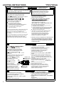
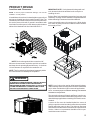
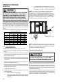
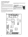
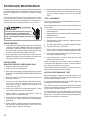
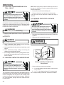
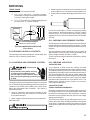
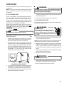
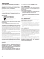
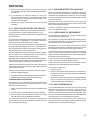
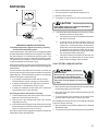
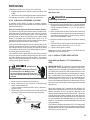
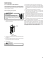
1. Remove the heating compartment door.
2. Turn of the power or open the thermostat circuit.
3. Reset the rollout control.
4. Turn power on and put the unit into a call for heating.
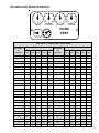
VOLT / O HM
M ETER
CAUTION
RED
RESET
B U T TO N
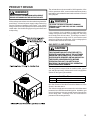
Flame rollout could occur. Keep face and hands a
safe distance from burner area.
5.
COLOR
ID EN TIFYIN G
TA B
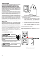
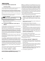
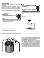
Look under the heat shield as the unit is running. Flames
should be drawn into firing tubes.
a.
If only one burners flame is not drawn into the tube,
that tube is restricted.
b.
If, without the air circulation blower running, all
flames are not drawn into the tubes either the
collector box, combustion blower, or flue outlet is
obstructed. If the combustion blower or flue outlet
is obstructed, the pressure switch should have
opened preventing the unit from firing, also inspect
the unit pressure switch and wiring.
c.
If the burner flame is not drawn into the tube only
when the air circulation blower is running, then a
cracked heat exchanger tube is present.
CHECKING FLAME ROLLOUT SWITCH
Limit Switch Operation (Applies to Primary, Auxiliary,
and Roll Out Limits) DSI systems.
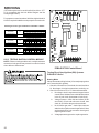
If a limit switch opens, the indoor blower is energized on heat
speed and the induced draft blower is energized. The LED on
the control flashes "4" to indicate an open limit switch. The
blower and inducer remain on while the limit switch is open.
The gas valve is de-energized. Power to the thermostat "R"
is removed while the limit switch is open.
When the limit switch re-closes, the induced draft motor runs
through its post purge and the indoor blower goes through the
heat off delay.
If a call for heat exists when the limit switch re-closes, the
control goes through a pre-purge period and then makes an
ignition attempt. The indoor blower remains on (for the delay
off time) during the re-ignition attempt.
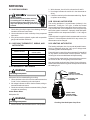
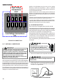
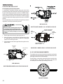
1. If no voltage is measured on either side of control it
indicates ignition control or wiring to control problem.
2. If voltage is measured on one side of the control and
not the other, it indicates the control is open.
3. If voltage is measured on both sides of the control the
wiring to gas valve or valve is at fault.
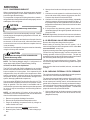
S-303 TESTING INDUCER MOTOR
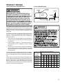
HIGH VOLTAGE!
Disconnect ALL power before servicing
or installing this unit. Multiple power
sources may be present. Failure to do so
may cause property damage, personal injury
or death.
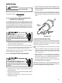
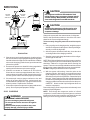
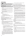
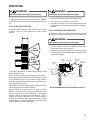
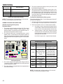
1. Disconnect the motor wire leads from its connection point
at integrated ignition control module.
Servicing procedure with furnace not firing.
2. Using and ohmmeter, test for continuity between each of
the motor leads.
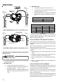
1. Confirm that the outer door was in place and all screws
tightened. (No leaks under the door.)
3. Touch one probe of the ohmmeter to the motor frame
(ground) and the other probe in turn to each lead.
2. Check to see if any damage was done to the furnace
especially the wiring.
If the windings do not test continuous or a reading is obtained
to ground, replace the motor.
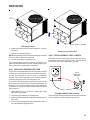
3. Confirm that heat exchanger is not obstructed by feeling
for discharge air from the flue hood when the combustion
blower is running but the unit is not firing.
4. After completing check and/or replacement of induced
draft blower motor.
If the above steps do not suggest the reason the control has
tripped the furnace should be fired.
5. Turn on electrical power and verify proper unit operation.
51