1
SERVICE MANUAL
CM 12
SERIAL NUMBER FROM JANUARY 2009 (0109) TO PRESENT
DocID: 00G00027EB
© 2010 DENSO SALES CALIFORNIA, INC.
All rights reserved. This book may not be reproduced or copied, in
whole or in part, without the written permission of the publisher. DENSO
SALES CALIFORNIA, INC. reserves the right to make changes without
prior notice. MovinCool is a registered trademark of DENSO
Corporation.
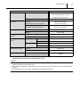
Table of Contents
Table of Contents
Operation Section
1. PRECAUTIONS FOR SAFETY
1.1
Foreword. . . . . . . . . . . . . . . . . . . . . . . . . . . . . . . . . . . . . . . . . . . . . . . . . . . . . . . . . . . . . . . . . . . . . . . 6
1.2
Definition of Terms . . . . . . . . . . . . . . . . . . . . . . . . . . . . . . . . . . . . . . . . . . . . . . . . . . . . . . . . . . . . . . . 6
1.3
General Precautions . . . . . . . . . . . . . . . . . . . . . . . . . . . . . . . . . . . . . . . . . . . . . . . . . . . . . . . . . . . . . . 6
2. GENERAL DESCRIPTION
2.1
Spot Cooler . . . . . . . . . . . . . . . . . . . . . . . . . . . . . . . . . . . . . . . . . . . . . . . . . . . . . . . . . . . . . . . . . . . . . 7
2.2
Lightweight, Compact, Ceiling Mounted . . . . . . . . . . . . . . . . . . . . . . . . . . . . . . . . . . . . . . . . . . . . . . . 7
2.3
Commercial Controller Usage. . . . . . . . . . . . . . . . . . . . . . . . . . . . . . . . . . . . . . . . . . . . . . . . . . . . . . . 7
2.4
Energy Conservation . . . . . . . . . . . . . . . . . . . . . . . . . . . . . . . . . . . . . . . . . . . . . . . . . . . . . . . . . . . . . 7
2.5
Added Safety through the Use of a Fire Alarm . . . . . . . . . . . . . . . . . . . . . . . . . . . . . . . . . . . . . . . . . . 7
3. CONSTRUCTION
3.1
Exterior Dimensions . . . . . . . . . . . . . . . . . . . . . . . . . . . . . . . . . . . . . . . . . . . . . . . . . . . . . . . . . . . . . . 8
3.2
Exterior Components . . . . . . . . . . . . . . . . . . . . . . . . . . . . . . . . . . . . . . . . . . . . . . . . . . . . . . . . . . . . . 9
3.3
Internal Structure . . . . . . . . . . . . . . . . . . . . . . . . . . . . . . . . . . . . . . . . . . . . . . . . . . . . . . . . . . . . . . . 10
3.4
Basic Construction . . . . . . . . . . . . . . . . . . . . . . . . . . . . . . . . . . . . . . . . . . . . . . . . . . . . . . . . . . . . . . 11
3.5
Air Flow. . . . . . . . . . . . . . . . . . . . . . . . . . . . . . . . . . . . . . . . . . . . . . . . . . . . . . . . . . . . . . . . . . . . . . . 11
4. SPECIFICATIONS
4.1
Technical Specifications . . . . . . . . . . . . . . . . . . . . . . . . . . . . . . . . . . . . . . . . . . . . . . . . . . . . . . . . . . 12
4.2
Characteristics . . . . . . . . . . . . . . . . . . . . . . . . . . . . . . . . . . . . . . . . . . . . . . . . . . . . . . . . . . . . . . . . . 14
5. REFRIGERANT SYSTEM
5.1
Refrigerant System Construction . . . . . . . . . . . . . . . . . . . . . . . . . . . . . . . . . . . . . . . . . . . . . . . . . . . 15
5.2
Compressor . . . . . . . . . . . . . . . . . . . . . . . . . . . . . . . . . . . . . . . . . . . . . . . . . . . . . . . . . . . . . . . . . . . 16
5.3
Condenser . . . . . . . . . . . . . . . . . . . . . . . . . . . . . . . . . . . . . . . . . . . . . . . . . . . . . . . . . . . . . . . . . . . . 18
5.4
Capillary Tube. . . . . . . . . . . . . . . . . . . . . . . . . . . . . . . . . . . . . . . . . . . . . . . . . . . . . . . . . . . . . . . . . . 19
5.5
Evaporator . . . . . . . . . . . . . . . . . . . . . . . . . . . . . . . . . . . . . . . . . . . . . . . . . . . . . . . . . . . . . . . . . . . . 19
5.6
Accumulator . . . . . . . . . . . . . . . . . . . . . . . . . . . . . . . . . . . . . . . . . . . . . . . . . . . . . . . . . . . . . . . . . . . 19
6. ELECTRICAL SYSTEM
6.1
Circuit Diagram . . . . . . . . . . . . . . . . . . . . . . . . . . . . . . . . . . . . . . . . . . . . . . . . . . . . . . . . . . . . . . . . . 20
6.2
Control Box . . . . . . . . . . . . . . . . . . . . . . . . . . . . . . . . . . . . . . . . . . . . . . . . . . . . . . . . . . . . . . . . . . . . 21
6.3
Power Supply Requirements . . . . . . . . . . . . . . . . . . . . . . . . . . . . . . . . . . . . . . . . . . . . . . . . . . . . . . 22
6.4
Input Signal. . . . . . . . . . . . . . . . . . . . . . . . . . . . . . . . . . . . . . . . . . . . . . . . . . . . . . . . . . . . . . . . . . . . 22
6.5
Operation . . . . . . . . . . . . . . . . . . . . . . . . . . . . . . . . . . . . . . . . . . . . . . . . . . . . . . . . . . . . . . . . . . . . . 23
Table of Contents
6.6
Relay Board . . . . . . . . . . . . . . . . . . . . . . . . . . . . . . . . . . . . . . . . . . . . . . . . . . . . . . . . . . . . . . . . . . . 24
6.7
Compressor . . . . . . . . . . . . . . . . . . . . . . . . . . . . . . . . . . . . . . . . . . . . . . . . . . . . . . . . . . . . . . . . . . . 26
6.8
Fan Motor . . . . . . . . . . . . . . . . . . . . . . . . . . . . . . . . . . . . . . . . . . . . . . . . . . . . . . . . . . . . . . . . . . . . . 27
6.9
Capacitor . . . . . . . . . . . . . . . . . . . . . . . . . . . . . . . . . . . . . . . . . . . . . . . . . . . . . . . . . . . . . . . . . . . . . 28
6.10 Temperature Thermistor . . . . . . . . . . . . . . . . . . . . . . . . . . . . . . . . . . . . . . . . . . . . . . . . . . . . . . . . . . 28
6.11 Drain Pump. . . . . . . . . . . . . . . . . . . . . . . . . . . . . . . . . . . . . . . . . . . . . . . . . . . . . . . . . . . . . . . . . . . . 28
6.12 Float Switch . . . . . . . . . . . . . . . . . . . . . . . . . . . . . . . . . . . . . . . . . . . . . . . . . . . . . . . . . . . . . . . . . . . 29
Table of Contents
Repair Section
7. TROUBLESHOOTING
7.1
Troubleshooting Chart . . . . . . . . . . . . . . . . . . . . . . . . . . . . . . . . . . . . . . . . . . . . . . . . . . . . . . . . . . . 30
7.2
Alarm . . . . . . . . . . . . . . . . . . . . . . . . . . . . . . . . . . . . . . . . . . . . . . . . . . . . . . . . . . . . . . . . . . . . . . . . 31
7.3
Basic Inspection . . . . . . . . . . . . . . . . . . . . . . . . . . . . . . . . . . . . . . . . . . . . . . . . . . . . . . . . . . . . . . . . 33
8. DISASSEMBLY
8.1
Parts Construction . . . . . . . . . . . . . . . . . . . . . . . . . . . . . . . . . . . . . . . . . . . . . . . . . . . . . . . . . . . . . . 34
8.2
Disassembly . . . . . . . . . . . . . . . . . . . . . . . . . . . . . . . . . . . . . . . . . . . . . . . . . . . . . . . . . . . . . . . . . . . 35
8.3
Removal of Indoor Fan Assembly (for Evaporator) . . . . . . . . . . . . . . . . . . . . . . . . . . . . . . . . . . . . . 37
8.4
Removal of Outdoor Fan Assembly (for Condenser) . . . . . . . . . . . . . . . . . . . . . . . . . . . . . . . . . . . . 39
8.5
Removal of Electrical Parts. . . . . . . . . . . . . . . . . . . . . . . . . . . . . . . . . . . . . . . . . . . . . . . . . . . . . . . . 41
8.6
Inspection of Capacitor (For Fan Motor and Compressor) . . . . . . . . . . . . . . . . . . . . . . . . . . . . . . . . 44
8.7
Inspection of Compressor. . . . . . . . . . . . . . . . . . . . . . . . . . . . . . . . . . . . . . . . . . . . . . . . . . . . . . . . . 45
8.8
Inspection of Fan Motor . . . . . . . . . . . . . . . . . . . . . . . . . . . . . . . . . . . . . . . . . . . . . . . . . . . . . . . . . . 46
8.9
Inspection of Thermistor . . . . . . . . . . . . . . . . . . . . . . . . . . . . . . . . . . . . . . . . . . . . . . . . . . . . . . . . . . 47
8.10 Inspection of Wiring Connection . . . . . . . . . . . . . . . . . . . . . . . . . . . . . . . . . . . . . . . . . . . . . . . . . . . . 47
8.11 Inspection . . . . . . . . . . . . . . . . . . . . . . . . . . . . . . . . . . . . . . . . . . . . . . . . . . . . . . . . . . . . . . . . . . . . . 47
9. REFRIGERANT SYSTEM REPAIR
9.1
Repair of Refrigerant System . . . . . . . . . . . . . . . . . . . . . . . . . . . . . . . . . . . . . . . . . . . . . . . . . . . . . . 48
9.2
Removal of Refrigerant System Components . . . . . . . . . . . . . . . . . . . . . . . . . . . . . . . . . . . . . . . . . 50
9.3
Charging the System with R-410A Refrigerant. . . . . . . . . . . . . . . . . . . . . . . . . . . . . . . . . . . . . . . . . 51
9.4
Refrigerant Charging Work . . . . . . . . . . . . . . . . . . . . . . . . . . . . . . . . . . . . . . . . . . . . . . . . . . . . . . . . 56
10. REASSEMBLY
10.1 Removal of Unit . . . . . . . . . . . . . . . . . . . . . . . . . . . . . . . . . . . . . . . . . . . . . . . . . . . . . . . . . . . . . . . . 58
10.2 Compressor Mounting . . . . . . . . . . . . . . . . . . . . . . . . . . . . . . . . . . . . . . . . . . . . . . . . . . . . . . . . . . . 58
10.3 Indoor Fan Assembly . . . . . . . . . . . . . . . . . . . . . . . . . . . . . . . . . . . . . . . . . . . . . . . . . . . . . . . . . . . . 58
10.4 Outdoor Fan Assembly . . . . . . . . . . . . . . . . . . . . . . . . . . . . . . . . . . . . . . . . . . . . . . . . . . . . . . . . . . . 58
10.5 Wiring Notice . . . . . . . . . . . . . . . . . . . . . . . . . . . . . . . . . . . . . . . . . . . . . . . . . . . . . . . . . . . . . . . . . . 58
10.6 Perform the Inspection . . . . . . . . . . . . . . . . . . . . . . . . . . . . . . . . . . . . . . . . . . . . . . . . . . . . . . . . . . . 58
6
Operation Section
1. PRECAUTIONS FOR SAFETY
1.1 Foreword
• This manual has been published to service the MovinCool CM 12. Please use this service
manual only when servicing the CM 12.
1.2 Definition of Terms
WARNING
CAUTION
NOTE
Describes precautions that should be observed in order to prevent injury to
the user during installation or unit operation.
Describes precautions that should be observed in order to prevent damage to
the unit or its components, which may occur during installation or unit
operation if sufficient care is not taken.
Provides additional information that facilitates installation or unit operation.
1.3 General Precautions
WARNING
• All electrical work if necessary, should only be performed by qualified electrical
personnel. Repair to electrical components by non-certified technicians may result in
personal injury and/or damage to the unit. All electrical components replaced must be
genuine MovinCool parts, purchased from an authorized reseller.
• When handling refrigerant, always wear proper eye protection and do not allow the
refrigerant to come in contact with your skin.
• Do not expose refrigerant to an open flame.
• The proper electrical outlet for MovinCool units must be equipped with a “UL” approved
ground-fault breaker to prevent electrical shock from the unit.
• When brazing any tubing, always wear eye protection, and work only in a well ventilated
area.
• Disconnect power before servicing unit.
• Be careful of any sharp edges when working on unit.
Operation Section
7
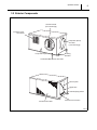
2. GENERAL DESCRIPTION
2.1 Spot Cooler
• In general, conventional air conditioners cool
the entire enclosed environment. They act as
"heat exchangers", requiring an interior unit
(evaporator) to blow cool air into the interior
Condenser
(Outdoor Unit)
and an exterior unit (condenser) to exhaust
Evaporator
(Indoor Unit)
exchanged heat to the outdoors.
• Unlike conventional air conditioners, the
MovinCool CM 12 is a spot cooler which
I000501
directs cool air to particular areas or objects.
The MovinCool CM 12 has the following features:
2.2 Lightweight, Compact, Ceiling Mounted
• Since the compact, lightweight, CM 12 can be easily installed in the ceiling, it allows for effective
use of floor space without interfering with room design. In addition, effective cooling is achieved
through the use of separate intake and discharge ducts within the room.
2.3 Commercial Controller Usage
• The CM 12 can use (Millivolt compatible thermostat) commercially available controllers, allowing
the user to select the controller best suited to the room design.
2.4 Energy Conservation
• The MovinCool CM 12 is economical because
it cools only the area or objects which need to
be cooled.
Condenser
Exhaust
Condenser
Intake
2.5 Added Safety through the Use of a
Fire Alarm
• The CM 12 can be automatically shutdown via
signals from a general fire alarm control panel
Cool Air
Supply
(Evaporator)
Room
Air Intake
I002841
and can also send out signal to monitoring devices such as environmental monitoring systems
or annunciator systems.
Operation Section
8
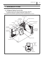
3. CONSTRUCTION
3.1 Exterior Dimensions
Wire For External
Equipment
Emergency Stop Switch
Ground Screw (M6)
With Washer
Wire For Thermostat
OPERATE
STOP
Connector
For Power Cord
(10.8)
Condenser Air Outlet
Fixing Hole (M4)
For Optional Outlet Ring
(7.7)
Drainage Pipe
Using Internal Drain Pump
(2.3)
Service Panel
Mount Bracket (t 0.08)
Thermistor
(2.0)
(6.3)
(4.5) (4.5)
(1.3)
(34.8)
33.6
(32.0)
(DIA. 0.6)
(7.6)
(DIA. 10.0)
(15.3)
(3.0)
(0.7)
(9.2)
(DIA. 10.0)
(3.5)
(8.1)
(2.8)
15.7
(19.9)
(2.7)
(0.6)
Condenser Air Inlet
4 x DIA. 0.6
(15.4)
Ring For Duct
(Evaporator Outlet Air)
Gravity Drainage Pipe
(With Cap,Clip and Packing)
Ring For Duct
(Evaporator Inlet Air)
Evaporator Air Outlet
(DIA. 0.6)
UNIT: inch
(1.0)
Evaporator Air Inlet
I002784
Operation Section
9
3.2 Exterior Components
Cold Air Exhaust
(10 in.Dia.Flange)
Condenser (Hot)
Air Exhaust
Evaporator (Room)
Air Intake
(10 in.Dia.Flange)
Pump Drain Pipe
Mounting
Brackets
Condensate Maintenance Pan Drain
Service panel
Signal Wire
Override (Stop) Switch
Condenser Air Intake
Power Cord Connection
I002750
10
Operation Section
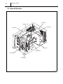
3.3 Internal Structure
Evaporator
Capillary Tube
Compressor
Condenser
Indoor Fan
Accumulator
Control Box
Outdoor Fan
I002751
Operation Section
11
3.4 Basic Construction
• The
MovinCool
CM
12
is
compact
in
construction due to the condenser and
Control Box
Condenser
Evaporator
evaporator being enclosed in one unit. The
interior of the unit is divided into two sections.
One section contains the evaporator which
cools room interior air. The other section is
comprised of the condenser, compressor and
control box.
Outdoor
Motor
Indoor
Motor
I000507
3.5 Air Flow
• Air drawn from the rear face passes over the
condenser which extracts heat from the
refrigerant. The hot air is blown out through the
Condenser
Exhaust
Condenser
Intake
front exhaust air vent. Air taken in from the
right side face is cooled by the evaporator and
then blown through the front cool air duct.
Cool Air
Supply
(Evaporator)
Room
Air Intake
I002841
Operation Section
12
4. SPECIFICATIONS
4.1 Technical Specifications
ITEM
Electronic Features
SPECIFICATIONS
Operation
Wall Thermostat
Control
Electronic Characteristics
Electronic
Voltage Requirement
Single-Phase 115 V, 60 Hz
Min.- Max. Voltage
Min. 105 V, Max. 127 V
Starting Current
50 A
Recommended Fuse Size
15 A
Cooling Capacity and Power Consumption
Evaporator: 80°F (27°C), Total Cooling Capacity *1
10500 Btu/h (3090 W)
50% RH/
7200 Btu/h (2100 W)
Condenser: 95°F (35°C),
40% RH
Sensible Cooling Capacity *1
Power Consumption *1
Current Consumption
1.23 kW
*1
Power Factor
Refrigerant Circuit
Compressor
99%
Compression Type
Output
Evaporator
0.91 kW
Plate Fin
Condenser
Plate Fin
Type of Fan
Centrifugal Fan
High
324 CFM (550 m3/h)
Low
228 CFM (390 m3/h)
Max. External Static Pressure
Motor Output
0.04 kW
Low
0.01 kW
Centrifugal Fan
High
700 CFM (1190 m3/h)
Low
370 CFM (630 m3/h)
Max. External Static Pressure
Motor Output
Type
Amount
0.16 IWG (40 Pa)
High
Type of Fan
Air Flow
Refrigerant
Hermetic Rotary
Evaporator
Air Flow
Condenser
11.2 A
0.12 IWG (30 Pa)
High
0.10 kW
Low
0.03 kW
R-410A
1.23 lb (0.56 kg)
Operation Section
Signal Connection
ITEM
SPECIFICATIONS
Fire Alarm Input
• Dry contact type (recommended)
13
• No-voltage contact input/Contact
resistance less than 100 ohm
Warning Signal Output
Dimension
2 A at 30 V (DC/AC) or less (resistive load)
WxDxH
32.0 x 19.9 x 14.8 in
(without flange and mounting bracket)
WxDxH
34.8 x 22.7 x 15.4 in
(with flange and mounting bracket)
Weight
128 lb (58 kg)
Shipping
141 lb (64 kg)
Pump Rate
Capacity
Head
Operating Condition
Evaporator
*2
Condenser
Maximum Duct Length
Maximum Sound Level
(884 x 577 x 391 mm)
Net
Condensate Pump
Range
(813 x 505 x 376 mm)
5.0 gal/h (19 L/h)
4 ft (1.2 m)
Max. Inlet Air
95°F (35°C), 50% RH
Min. Inlet Air
65°F (18°C), 50% RH
Max. Inlet Air
113°F (45°C)
Min. Inlet Air
65°F (18°C)
Cold Duct *3
20 ft (6.1 m)
Hot Duct *3
10 ft (3.0 m)
Measured at 1 m under the
ceiling with evaporator duct and ceiling tile.
52 dB(A)
• Specifications are subject to change without notice.
< NOTE >
*1 : With two 6-foot (1.8 m) ducts containing one 90° bend each, supply grill and return grill with filter {0.16 IWG (40 Pa)
external static pressure} on high fan speed.
*2 : When ambient temperature is lower than 65°F (18°C), operation may be interrupted due to anti-freeze protection
activation.
*3 : Confirm pressure drop of duct, grills, and filter with manufactures specifications.
Operation Section
4.2 Characteristics
Cooling Capability Curve
Cool Air Temperature Difference Curve
14
10
13 (23.4)
8
Dry Bulb Temp.°C (°F)
#Outdoor Temp. at 95F
14 (25.2)
Delta-T °C (°F)
12
15 (27.0)
Ou
t
Ou doo
rT
tdo
em
Ou
or
p.
Te
tdo
mp 65F
or
.95
Te
mp
F
.11
3F
3
Cooling capacity (x10 Btu/h)
16
12 (21.6)
11 (19.8)
10 (18.0)
9 (16.2)
35 (95)
8 (14.4)
30 (86)
7(12.6)
30
40
25 (77)
50
60
70
80
Relative Humidity (%)
20 (68)
10
(50)
15
(59)
20
(68)
25
(77)
Wet Bulb Temp.°C (°F)
Power Consumption Curve
Current Consumption Curve
1.6
F
or
utdo
p
Tem
14.0
Current Consumption (A)
Power Consumption (kW)
.113
O
1.4
.95F
or
utdo
p
Tem
O
1.2
.65F
mp
r Te
tdoo
Ou
1.0
3F
p.11
Tem
r
o
o
5F
Outd
mp.9
or Te
o
d
t
Ou
12.0
.65F
emp
oor T
Outd
10.0
8.0
35(95)
30(86)
25(77)
20(68)
20
(68)
25
(77)
30
(86)
35
(95)
Wet Bulb Temp.°C (°F)
Dry Bulb Temp. °C (°F)
0.8
Dry Bulb Temp.°C (°F)
14
35(95)
30(86)
25(77)
20(68)
20
(68)
25
(77)
30
(86)
35
(95)
Wet Bulb Temp.°C (°F)
I002785
Operation Section
15
5. REFRIGERANT SYSTEM
5.1 Refrigerant System Construction
The component parts of the refrigerant system include the following:
• Compressor, Evaporator, Condenser, Accumulator, Capillary tube
These parts are all connected by copper tubing. All the connections have been brazed.
Connecting Pipe
Compressor
Discharge Pipe
Evaporator Inlet Pipe
Capillary Tube
Evaporator Outlet Pipe Assy
Condenser
Evaporator
Connecting Tube
Condenser
Outlet Pipe
Compressor
Suction Pipe
(Insulated)
Condenser
Inlet Pipe
Accumulator
Compressor
Refrigerant
Flow
Condenser
Accumulator
Capillary
Tube
Fan
Motor
Evaporator
Compressor
I002752
16
Operation Section
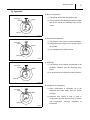
5.2 Compressor
• The compressor used for the unit is hermetically sealed. The compressor and the compressor
motor are in one casing.
(1) Compressor construction
• The construction of a rotary type compressor is
divided into two mechanisms; the drive
mechanism (compressor motor), and the
compression mechanism (compressor). When
the rotor shaft of the motor (drive mechanism)
turns, the roller (compression mechanism)
rotates to compress the refrigerant.
I002753
(2) Basic compressor operation
• The roller (compression mechanism) is set
eccentrically with a certain distance given from
the axis of the center of the cylinder. A spring
Discharge
Hole
Discharge
Valve
loaded blade is mounted on the cylinder. The
Spring
Suction
Hole
Blade
roller turns to compress the refrigerant in the
space between the cylinder and eccentrically
mounted roller. The blade is in contact with the
Shaft
Roller
roller by means of spring force. The blade
Cylinder
I000510
partitions the space between the suction side
and the discharge side to keep compressed refrigerant from returning to the suction side. There
is no suction valve. The discharge valve is designed not to open until the pressure of the
refrigerant within the cylinder reaches or exceeds discharge side pressure. As a result, the
discharge valve prevents the backward flow of refrigerant gas.
Operation Section
17
(3) Operation
1) Start of compression
Discharge
Valve
1) The cylinder is filled with low pressure gas.
Blade
2) Since pressure in the discharge chamber is higher
than in the cylinder, the discharge valve is kept
closed.
Roller
I001676
2) Suction and compression
Discharge
Valve
1) The pressure in the cylinder increases gradually.
2) Refrigerant suction begins on the suction side of
Blade
the cylinder.
3) The discharge valve remains closed.
Roller
I001677
3) Discharge
Discharge
Valve
1) The pressure in the cylinder exceeds that in the
discharge chamber, and the discharge valve
Blade
opens.
2) On the suction side, refrigerant suction continues.
Roller
I001678
4) Completion of compression
1) When compression is completed, all of the
Discharge
Valve
refrigerant has been drawn from the suction
Blade
chamber.
2) Operation then returns to step 1) (Start of
compression) and the above process of suction
and
Roller
compression
succession.
I001679
continues
repeatedly
in
18
Operation Section
(4) Compressor lubrication
• The lubrication system is comprised of a
hollow shaft, an oil scraper mounted at the end
face, hollow shaft, a shaft journal (shaft
Rotor
bearing), and the lubrication groove for the
shaft journal. The lubrication groove is wider
than the oil hole. When the shaft turns, oil is
scraped upward by the oil scraper along the
Hollow Shaft
Eccentric Shaft
Cylinder
Roller
inside diameter of the hollow shaft. The oil is
fed through the oil hole by centrifugal force,
then supplied to the lubrication groove for each
shaft journal, lubricating the bearing. In this
lubrication system, oil enters into each bearing
separately and returns to the oil reservoir. This
system
effectively
temperature
increases,
prevents
and
Oil Feed Groove
Oil Hole
Oil Scrapper
bearing
offers
high
I001680
reliability. In addition, the specially treated
shaft journal keeps the bearing from being damaged during high temperature operation.
5.3 Condenser
• The condenser is a heat exchanger with
copper tubes that are covered with thin
aluminum projections called plate fins.
• Heat is given off and absorbed by air being
pulled across the condenser fins by the
centrifugal fan and then expelled through the
exhaust air duct.
I002754
Operation Section
19
5.4 Capillary Tube
• The capillary tube is a long thin tube utilizing
line flow resistance to serve as an expansion
High Temp./High Pressure
Liquid Refrigerant
valve. The length and the inner diameter of the
capillary tube are determined by the capacity of
the refrigeration system, specified operating
conditions, and the amount of refrigerant. The
capillary tube causes the high pressure, high
temperature liquid refrigerant sent from the
Low Temp./Low Pressure
Gas and Liquid Mixture
I001887
condenser to expand rapidly as the refrigerant
is sprayed out through the fixed orifice in the capillary tube. As a result, the temperature and
state of the refrigerant becomes low and mist-like respectively, causing it to evaporate easily.
5.5 Evaporator
• The evaporator is a heat exchanger covered
with plate fins. Heat is removed from the air
being pulled across the evaporator by the
centrifugal fan and the resulting cool air is
expelled through the cool air vent.
I002755
5.6 Accumulator
• The accumulator is mounted on the suction
From Evaporator
gas piping between the evaporator and the
compressor. The accumulator separates the
liquid refrigerant from the gas refrigerant,
allowing only the gas refrigerant to enter the
compressor. In the accumulator, suction gas is
led into a cylindrical vessel where the speed of
the gas is decreased. This process separates
To Compressor
I000514
the refrigerant contained in the gas by the force
of gravity, causing the refrigerant to accumulate at the bottom of the vessel. As a result, the
compressor is protected from possible damage caused by liquid refrigerant intake.
Operation Section
20
6. ELECTRICAL SYSTEM
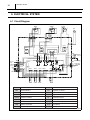
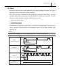
6.1 Circuit Diagram
ODFM
IDFM
R CM
OL C
DP
M
CN
1
6
1 CC 1
1 CF2 1
1 CF1 1
2
4
6
1
3
5
2
2
2
CN
1
GRAY
BLUE
RED
BLACK
WHITE
6
GRAY
BLUE
RED
BLACK
WHITE
S
2
7
TB2
CN25
5
G1
G
Y
RC
CN13
5
1
CN22
52OD2
CN17
YELLOW
ORANGE
RED
BROWN
1
CN12
CN11
1
CN21
SW
EMERGENCY
STOP S/W
3
2
1
CN24 RB
TB1
1
COM
52CT
52OD1
52ID
CN03
F1
115V
CN15 52CM
CN16
4
1
2
RX
CN23
RED
RED
BROWN
BROWN
Fire Alarm
INPUT
EXTERNAL
OUTPUT
8
2
R
T
R
T
GROUND(G)
AC115 V
1PHASE
60Hz
5
3
CN01
5
CONTROL BOX
ODS
CTS
FLTS
RTS
TB1
Terminal Block 1
RTS
Room Thermistor
TB2
Terminal Block 2
CF1
Capacitor For IDFM
RB
Relay Board
CF2
Capacitor For ODFM
IDFM
Indoor Fan Motor
CC
Capacitor For Compressor
ODFM
Outdoor Fan Motor
OL
Overload Protector
MC
Compressor Motor
DP
Drain Pump
RX
Auxiliary Relay
SW
Switch For Emergency
ODS
Outdoor Thermistor
CTS
Freeze Protection Thermistor
FLTS
G
Float Switch
Ground
I002756
Operation Section
21
6.2 Control Box
CC: Capacitor for Compressor
RB: Relay Board
RX: Auxiliary Relay
4-Position Dipswitch
7
4
1
3
5
2
4
6
3
8
+
2
+
ON
-
1
E
E
L
L
G1
G1
Y
RC
"OFF" Position
TB2: Terminal Block2
TB1: Terminal Block1
CF1: Capacitor for Indoor Fan Motor
G
CF2: Capacitor for Outdoor Fan Motor
I002757
Operation Section
22
6.3 Power Supply Requirements
• The CM 12 requires a single-phase 115 V, 60 Hz power supply.
• The power supply should be a dedicated single outlet circuit with a UL approved short-circuit
and ground fault protective breaker, and a maximum fuse size of 20 A.
R
T
G
Circuit Breaker with
Ground-Fault Protective
G
Fuse 20 A Max.
Ground
Terminal
CM12 Terminal Block
R
T
G
I002758
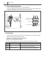
6.4 Input Signal
• Install the wall thermostat in a location inside the room where it can be conveniently accessed.
• Most thermostats provide these basic functions:
Fan Mode: On / Auto (Selects the desired fan mode.)
System: Cool / Heater (Selects Cool only.)
• The
CM 12 receives signals from the wall thermostat to perform the following operations..
Connector
Y
G
G1
Signal Name
Function
Compressor ON / OFF Signal
When both Y and G signals are ON, the compressor comes ON.
Indoor Fan ON / OFF Signal
When the G signal is ON, the indoor fan comes ON.
(When the signal is OFF, the indoor fan goes OFF.)
Indoor Fan Hi / Lo Signal
When the G1 signal is ON, the indoor fan speed switches to Lo.
(When the signal is OFF, the indoor fan speed switches to Hi.)
Operation Section
23
6.5 Operation
(1) Basic operation
• When a Y signal is input, the 52CM relay located on the relay board comes ON, and the
compressor operates.
• When a G signal is input, both the 52ID relay and the RX (auxiliary relay) come ON, and the
indoor and outdoor fans operate. However, when the G signal is OFF, both the 52CM and 52ID
relays go OFF, stopping the compressor as well as the fans.
(2) Indoor fan speed control
• With a G signal on, the fan will start at high speed. When a G1 signal is input, relay 52ID will
become active and fan speed changes from high to low.
(3) Outdoor fan speed control (Air Volume Control)
• Outdoor fan (condenser fan) air volume is
controlled by the ODS (Outdoor Thermistor:
ambient temperature).
• When room temperature is approx. 77 °F (25
(Low)
Outdoor Fan
°C) or greater...
Outdoor Fan Speed switches to high
(High)
Ambient Temperature
• When room temperature is approx. 73 °F (23
°C) or less...
73°F
(23°C)
77°F
(25°C)
I000518
Outdoor Fan Speed switches to low
< NOTE >
However, when the 52ID relay is ON and the ODS temperature is 73 °F (23 °C) or less, the outdoor
fan will switch to low speed after running in high speed for five sec.
(4) Anti-frost control
• Anti-frost controls turns the 52CM relay on in accordance with the Freeze Protection Thermistor
(CTS) temperature in order to turn the compressor on and off to prevent a decrease in cooling
performance resulting from a buildup of frost on the evaporator.
• Compressor off conditions: Freeze protection thermistor (CTS) temperature ≤ 30 °F (-1 °C)
• Compressor on (recovery) conditions: CTS temperature ≥ 50 °F (10 °C) and continuous antifrost control for 15 min.
24
Operation Section
(5) Compressor protection (Compressor time delay control)
• Compressor protection consists of a time delay program within the microprocessor which
prevents a heavy load from being applied to the compressor motor when restarting the unit (cool
mode) after a very short period of time. This “delay” is in effect any time when the compressor
is turned on by either the COOL ON/OFF button (after the Y signal goes OFF once and then
comes back ON), or power interruption restart. (automatic recovery)
Specifications:
- Time Delay: 120 sec.
(6) Automatic restart after power interruption (Automatic Recovery Function)
• The program within the CM 12 microprocessor contains a feature that will automatically restart
the unit after power is lost and then regained. The unit also has memory in order to return itself
back to the operating mode (either manual or preset program) it was in prior to the loss of power.
Any “preset” program will also be retained in the memory in the event power loss occurs.
6.6 Relay Board
• The relay board receives signals and outputs from the control board that contains a
microprocessor. The relay board contains the compressor, fan on and fan mode (speed) relays.
• It also contains a step-down transformer that converts the line voltage (115 VAC) to 12 V.
• This 12 V is then converted from AC to DC and used for relay coil activation. The 12 V (DC)
power is sent to the control panel assembly where it is further reduced to 5 V for the system logic.
• The relay board also contains the DIP switch.
< NOTE >
The relay board must be serviced as a complete assembly. It has only one serviceable
component, the fuse. (see below)
(1) Relay board fuse
• This fuse provides protection against damage to the step-down transformer. The fuse must be
replaced with the exact same part, or a suitable equivalent.
Specifications:
- 5 A 250 VAC
CAUTION
Failure to use the exact type of fuse could result in damage to the unit and/or to components. It
could also void the warranty of the unit.
Operation Section
25
(2) Dip switch setting
• The controller is equipped with a four position dip switch that defaults in the OFF position. The
dip switch can be set to configure the following functions:
Switch
Setting Name
Function
DSW4
Alarm Setting
When DSW 4 is ON, the buzzer sound function is disabled.
DSW3
Compressor Time Delay Cut
When DSW 3 is ON, the compressor delay timer function is disabled.
Cooling Test Operation
When DSW 2 is ON, the compressor, evaporator and condenser fan
DSW2
motor will turn ON. This function is used for test purposes and verification.
Discharge Air Test Operation
DSW1
When DSW 1 is ON, the evaporator and condenser fan motor will turn
ON. This function is used for test purposes and verification.
4-Position Dipswitch
ON
1
2
3
4
Relay Board Fuse (5A)
"OFF" Position
I002759
26
Operation Section
6.7 Compressor
(1) Compressor motor
• The compressor motor is a single-phase motor
and is contained within the same housing as
the compressor.
Specifications:
- Rated Voltage: 115 V
- Rated Output: 890 W
I002753
(2) Compressor overload relay
• An external compressor overload relay is used
Bimetal
to protect the compressor motor. This relay is
mounted within the connector housing that
attaches to the top of the compressor. The
Points
relay interrupts the flow of current when there
is an overload condition and, high temperature
builds up in the compressor.
Terminal
Specifications:
Temperature
Contact
Open
302°F (150°C)
Contact
Close
142°F (61°C)
Overcurrent
17 A 30 min
(at 212°F (100°C))
I001691
Operation Section
27
6.8 Fan Motor
(1) Indoor Fan Motor
• The indoor fan motor is a single phase,
induction type two-speed motor.
Specifications:
- Rated Voltage: 115 V, 60 Hz
- Rated Output: High - 41.28 W, Low - 12.08 W
- Rotational Speed: High - 1018 rpm, Low 671 rpm
I000520
< NOTE >
An internal overload relay is used to protect the fan motor. This relay is built into the fan motor and
interrupts the flow of current when there is an over current situation, or if abnormally high
temperature builds up in the fan motor.
(2) Outdoor Fan Motor
• The outdoor fan motor is a single phase,
induction type two-speed motor.
Specifications:
- Rated Voltage: 115 V, 60 Hz
- Rated Output: High - 99.6 W, Low - 27.3 W
- Rotational Speed: High - 1100 rpm, Low - 697
rpm
I002786
< NOTE >
An internal overload relay is used to protect the fan motor. This relay is built into the fan motor and
interrupts the flow of current when there is an over current situation, or if abnormally high
temperature builds up in the fan motor.
28
Operation Section
6.9 Capacitor
• The capacitor is used to improve the rotational
power of the fan motors and compressor at
startup. The specification for each capacitor is
shown below.
Rated
Capacitor
Voltage
Capacitance
Indoor Fan Motor
250 V
7 µF
Outdoor Fan Motor
220 V
9 µF
Compressor
370 V
60 µF
Check capacitance
I001693
6.10 Temperature Thermistor
• The
room
thermistor
(RTS)
is
installed
upstream of the evaporator, and detects
evaporator inlet temperature as a resistance
value.
• The freeze protection thermistor (CTS) is
installed in the evaporator outlet piping, and
detects low temperature on the evaporator as
a resistance value.
I001695
Specification
Type
Characteristic
Room Thermistor (RTS)
Freeze Protection
Thermistor (CTS)
“Short” Detection
“Open” Detection
5 k ohm at 77 °F (25 °C)
181 °F (83 °C) or more
-29 °F (-34 °C) or less
5 k ohm at 77 °F (25 °C)
181 °F (83 °C) or more
-29 °F (-34 °C) or less
6.11 Drain Pump
• The
drain
pump
evacuates
evaporator
condensation accumulated in the drain pan.
Drain
pump
operation
is
coupled
with
compressor operation.
I000523
Operation Section
29
6.12 Float Switch
• A float switch is installed in the drain pan. The
float switch is a normally closed type switch. If
evaporator condensation cannot be evacuated
and the drain pan becomes full, the float rises,
turning the switch OFF, which then halts relay
CM 12 operation. This prevents the drain pan
from overflowing and alerts the user of an
abnormality.
I000524
Repair Section
30
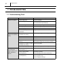
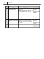
7. TROUBLESHOOTING
7.1 Troubleshooting Chart
Condition
Unit does not operate.
Possible Cause
Remedy
1. Power supply is off.
Check circuit breaker.
2. Power interruption.
Unit will turn on automatically when power returns
(some thermostats require resetting.)
3. Air duct blockage.
Check duct for any blockage or excessive kinks.
4. OFF signal input.
Check for OFF signal input (fire alarm control panel.)
5. Override (Stop) switch is active
Ensure the switch is in the “OPERATE” position.
6. Battery depleted by the
Change battery.
thermostat.
Insufficient cooling / Unit 1. Condenser air intake or outlet Check for any blockages in the ceiling.
operation interrupted frequently.
blockage in the ceiling.
2. Dirty condenser core surface.
Clean condenser core surface.
3. Dirty / blocked filters.
Clean / replace air filter.
4. Excessive evaporator air
Evaporator ducting should not exceed 30’ and bend
ducting.
radius should be larger than twice the duct diameter.
5. Condenser air intake or outlet Remove the blockage.
blockage in the ceiling.
Beeping / Alarm coming
from unit and unit
stopped. (Buzzer sound
pattern indicated on
page 31)
6. Outside operating range.
Use within operating temperature range.
1. Internal thermistor failure
Replace internal thermistor.
(Sound pattern 1)
2. Pump or drain problem
(sound pattern 2)
3. Refrigeration system problem
(sound pattern 3)
Check drain connection.
Check for blockage, kink or bend in drain hose.
Check for leakage.
Check compressor relay.
Check for refrigerant blockage.
Repair Section
31
7.2 Alarm
• An alarm is emitted when a system abnormality is detected, stopping the system. The type of
abnormality can be recognized by the alarm pattern.
• The CM 12 controller is equipped with a warning signal output-type relay (Form-C, normally
open dry contact), which can be used for monitoring the CM 12 abnormality conditions. The relay
contactor is closed when the following conditions have occurred:
- Temperature sensor failure
- Condensation overflow
- Cooling function failure
• The relay output is rated for 5 A at 30 VDC or 5 A at 250 VAC (resistive load). The relay can be
used to connect to warning devices with compatible outputs such as alarm speakers, light
indicators, etc.
< NOTE >
However,when dipswitch no. 4 on the relay board is OFF, an alarm will not sound.
ON
OFF
Pattern 1
0.5sec
(Internal thermister failure)
4sec
Pattern 2
ON
OFF
0.5sec
(Pump or drain problem)
4sec
ON
OFF
Pattern 3
(Refrigeration system problem)
0.5sec
1sec
Pattern 4
ON
(Fire alarm signal input)
I002772
Repair Section
32
Alarm
Pattern
Cause
Detection Details
Alarm Clear Method
Temperature sensor failure
When an abnormality is detected in either RTS, Unplug the unit and
(Thermistor short / failure)
CTS, or ODS.
plug it back in.
Detection value: Below 136.5 k ohm (93.2 °F (34 or
1
°C)) or above 566 k ohm (181.4 °F (83 °C)).
Reset the power from
the breaker.
Condensation overflow
When the float switch is OFF continuously for 60 Unplug the unit and
(Water leak detection)
sec.
plug it back in.
or
2
Reset the power from
the breaker.
Cooling function failure
When the following occurs 3 times.
Unplug the unit and
(Refrigeration cycle abnormality)
When 20 min from the start of operation has
plug it back in.
elapsed, RTS - CTS < 23 °F (5 °C) continuously
or
for one minute.
Reset the power from
3
the breaker.
Fire alarm
4
When receiving fire alarm signal input.
Reset
the
power
source or turn the wall
thermostat off and on.
Repair Section
33
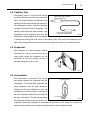
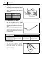
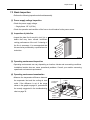
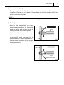
7.3 Basic Inspection
• Perform the following inspections before disassembly.
(1) Power supply voltage inspection
• Check the power supply voltage.
- Single phase 115 V (60 Hz)
• Check the operation and condition of the fuse or circuit breaker for the power source.
(2) Inspection of plate fins
• Inspect the plate fins for any dirt, dust, lint, or
debris that may have caused insufficient
cooling performance of the unit. If cleaning of
the fins is necessary, it is recommended that
this service be performed by a qualified service
technician.
I001780
(3) Operating environment inspection
• Operating environments can vary depending on location, climate and surrounding conditions.
Installation location also can cause operational problems. Consult your reseller concerning
operational environment requirements.
(4) Operating environment examination
• Measure the temperature difference between
the evaporator inlet and the cooling air duct
outlet. If the difference is out of the range
Condenser
Exhaust
Condenser
Intake
shown in the graphs on page 14, proceed with
the remedy suggested in the troubleshooting
chart on page 30.
Cool Air
Supply
(Evaporator)
Room
Air Intake
I002841
Repair Section
34
8. DISASSEMBLY
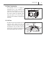
8.1 Parts Construction
Right Side Panel
Top Panel
Condenser
Outdoor Thermistor
(ODS)
Capillary Tube
Room Thermistor (RTS)
Freeze Protection
Thermistor (CTS)
Evaporator
Frame
Wire
Indoor Fan
Outdoor Fan
Drain Pan
Compressor
Float Switch
Drain
Pump
Controller
Frame
Left Side Panel
Service Panel
Front Panel
I002760
Repair Section
35
8.2 Disassembly
1) Take out the four (4) screws, and then remove
the service panel.
Screws (4)
Service Panel
I002761
2) Disconnect the two power supply lines from the
terminal, and disconnect the ground line.
CAUTION
Terminal
• Ground tightening torque:
- 0.74 ± 0.15 ft•lbf (1.0 ± 0.2 N•m)
Power Supply Line
Ground Line
I002762
3) Take out the eighteen (18) screws, and then
Screws (3)
Top Panel
Screws(2)
Screws (4)
Screws (4)
Screws (5)
Top Panel
I002763
remove the top panel.
36
Repair Section
Front Panel
4) Take out the sixteen (16) screws, and then
Screws(3)
remove the front panel.
Screws(9)
Screws(4)
I002764
5) After disconnecting the relay connector (white,
two-pin), please remove the drain pump referring
to pattern 1 or 2.
Connector
Hose Clip
I002766
Pattern 1 :
Nuts (2)
Take off the three (3) nuts, and remove the hose
Pump
Nut (1)
clip, and remove the drain pump assy.
I002787
Screw (1)
Screws (3)
Pattern 2 :
Take out the four (4) screws, and remove the
drain pump.
Pump
I002765
Repair Section
37
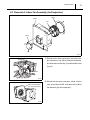
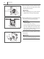
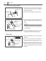
8.3 Removal of Indoor Fan Assembly (for Evaporator)
Ring
Frame
Fan
Motor
I002773
1) Disconnect the three connectors (two white, two-
Screws (2)
pin connectors; one white, three-pin connector),
and then take out the two (2) screws and the two
(2) nuts.
Connectors
Nuts (2)
I002767
2) Disconnect the motor connector (white, six-pin)
Indoor Fan Assembly
(For The Evaporator)
I000537
from circuit board CN23, and remove the indoor
fan assembly (for the evaporator).
38
Repair Section
3) Take out the three (3) screws, and then remove
the ring. Loosen the set screw with an Allen
Fan
wrench and remove the fan.
Set Screw
CAUTION
Straight Surface
When assembling the ring, ensure that the
Screws (3)
straight surface of the ring is facing forward.
Ring
I002774
0.12 in (3 mm)
or more
0.12 in (3 mm)
or more
4) When assembling the fan, ensure that the screws
align with the motor axis positioning holes.
CAUTION
Set Screw
• Tightening torque:
- 3.7 ± 1.1 ft•lbf (5.0 ± 1.5 N•m)
• Verify the clearance between the fan and case
Motor Axis
I002775
ring. After installing the fan and fan motor,
ensure that the clearance between the fan and
case ring is at least 0.12 in (3 mm).
5) Take out the four (4) screws, and then remove
the fan motor.
CAUTION
Motor
When assembling the motor, ensure that the
Screws (4)
wire connection ends are facing down.
Wire Connection
I002776
Repair Section
39
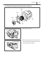
8.4 Removal of Outdoor Fan Assembly (for Condenser)
FRAME
FRAME
MOTOR
RING
FAN
I002777
1) Take off the four (4) nuts.
Nuts (4)
I002778
2) Disconnect the motor connector (white, six-pin)
Outdoor Fan Assembly
(For The Condenser)
I000544
from circuit board CN22, and remove the indoor
fan assembly (for the condenser).
40
Repair Section
3) Take out the three (3) screws, and then remove
the ring. Loosen the set screw with an Allen
Fan
wrench and remove the fan.
Set Screw
CAUTION
When assembling the ring, ensure that the
Screws (3)
straight surface of the ring is facing forward.
Ring
I002779
0.12 in (3mm)
or more
0.12 in (3mm)
or more
4) When assembling the fan, ensure that the screws
align with the motor axis positioning holes.
CAUTION
Set Screw
• Tightening torque:
- 10.80 ± 2.17 ft•lbf (14.7 ± 3.0 N•m)
• Verify the clearance between the fan and case
Motor Axis
I002780
ring. After installing the fan and fan motor,
ensure that the clearance between the fan and
case ring is at least 0.12 in (3 mm).
5) Take out the three (3) screws, and then remove
Screws (3)
Motor
the fan motor.
CAUTION
When assembling the motor, ensure that the
wire connection ends are facing down.
Wire Connection
I002781
Repair Section
41
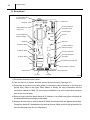
8.5 Removal of Electrical Parts
Box
Capacitor for Compressor
Stand-off
Relay Board
Condenser
Relay
Capacitor
for Indoor Fan Motor
Wire
Capacitor
for Outdoor Fan Motor
Terminal
Plate
Terminal
I002768
42
Repair Section
(1) Relay Board
To Terminal Block1
(Power Source)
CN01
Stand-Off
Stand-Off
To Terminal Block2
(Fire Alarm Input)
Relay Board Fuse
(250 V, 5 A)
To Float Switch
CN15
To Terminal Block2
(External Output)
Stand-Off
Not Use
CN16
CN14
CN24
To Auxiliary Relay
To Terminal Block2
(Wall Thermostat)
4
To OD Fan Motor
CN03
CN21
To Room Thermistor
3
To ID Fan Motor
Stand-Off
CN22
CN11
CN12
To Freeze Protection
Thermistor
Dip Switch (See Page 25)
CN23
CN13
CN25
CN17
Stand-Off
To Outdoor Thermistor
Stand-Off
Not Use
Not Use
I003160
1) Disconnect the power at the source.
2) Take out the four (4) screws, and then remove the service panel. (See page 35.)
3) Disconnect all connectors from relay board (11 connectors, two connections on the relay and
ground wire). Refer to the figure “Relay Board” to identify the relay connections and the
connectors marked as CN##. (To ensure easy reinstallation, be sure to label each connector
wire as you remove them)
4) Remove relay board from plastic stand-off (6 locations). Use needle nose pliers to squeeze all
the stand-offs before removing the relay board.
5) Replace the new relay on existing stand-off (Make sure all stand-offs are aligned horizontally).
Change the stand-off if damaged during removal process. Make sure that the dip switches on
the new relay board are all set to off positions.
Repair Section
43
6) Reconnect all 11 connectors to the new relay board and make sure connector label 52CM3 is
connected to terminal #3 and connector label 52CM4 is connected to terminal #4 of the relay.
Also, connect the ground wire and make sure they are all properly connected. Refer to the figure
“Relay Board” to identify the connectors that need to be connected.
7) Reconnect the power at the source and turn on the unit to verify the function and operation of
the unit. Turn off the unit.
8) Close the service panel and secure with four (4) screws.
< NOTE >
• Please use the following procedure in case there is no room to remove and replace the relay
board.
- After perform above 1) to 2), Take out the eighteen (18) screws, and then remove the top
panel.
44
Repair Section
8.6 Inspection of Capacitor (For Fan Motor and Compressor)
(1) Ohm-meter method
Control Box
• Set the ohm-meter to the 10M range. Place the
two probes against the two terminals of the
CC: Capacitor for
Compressor
capacitor. At first, the ohm-meter should
indicate small value, then the reading should
gradually
increase
towards
infinity.
This
indicates that the capacitor is charging. If the
reading indicates infinity right away (open) or
CF1: Capacitor for
Indoor Fan Motor
CF2: Capacitor for
Outdoor Fan Motor
I002782
the ohm-meter fails to move from 0. (shorted),
replace the capacitor.
(2) Capacitance tester method
• Using a capacitance tester and the chart on page 28, test the capacitor for the value indicated.
If the value tested is not within 10 % of indicated capacitance, replace the capacitor.
Capacitor Application
Voltage
Rating Capacitance
Indoor Fan Motor
250 V
7 µF
Outdoor Fan Motor
220 V
9 µF
Compressor
370 V
60 µF
WARNING
• Properly discharge the capacitor(s) before testing and after testing has been completed.
• Failure to do so could cause damage to test equipment or the unit and/or result in
personal injury (electrical shock) or death.
Repair Section
45
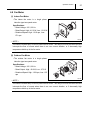
8.7 Inspection of Compressor
(1) Compressor motor
C
• Measure resistance across the terminals of the
R
compressor motor.
S
• Between terminals (at 77 °F (25 °C))
- R-C Approx. 0.49 - 0.8 ohm
- C-S Approx. 1.9 - 3.3 ohm
• If the measured resistance is not equal to the
standard values listed above, replace the
I002770
compressor. The compressor has an external overload relay. The overload relay should be
operational if the above resistance is obtained under normal temperature. For overload relay
specifications, see chart on page 26.
(2) Overlord relay
• Check for continuity across two terminals of the
overload relay. At normal temperature, there
should be continuity across the terminals.
Operating Temperature
OFF (open contacts)
ON (closed contacts)
302 °F (150 °C)
142 °F (61 °C)
• If there is no continuity across the terminals,
replace the overload relay.
I001701
46
Repair Section
8.8 Inspection of Fan Motor
(1) Indoor fan motor
• Measure resistance across the terminals of the
fan motor.
Blue
Black
Lo
WA1
Hi
P
• Terminals (at 68 °F (20 °C))
WM
AC115V
60Hz
- Black-White Approx. 35.5 ohm
- Black-Blue Approx. 23.35 ohm
- Black-Red Approx. 28.23 ohm
WA2
C
White
• If the measured resistance is not equal to the
Gray
7uF
250VAC
Red
I000541
standard values listed above, replace the fan
motor.
(2) Outdoor fan motor
• Measure resistance across the terminals of the fan motor.
• Between terminals (at 68 °F (20 °C))
- Black-White Approx. 15.38 ohm
- Black-Blue Approx. 12.59 ohm
- Black-Red Approx. 13.09 ohm
• If the measured resistance is not equal to the standard values listed above, replace the fan
motor.
Repair Section
47
8.9 Inspection of Thermistor
• Using an Ohm-meter, check the resistance value across the 2-pin connector. At normal
temperature (77 °F (25 °C)) all thermistors (room, freeze, or outdoor) should measure
approximately 5 k ohm.
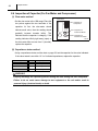
8.10 Inspection of Wiring Connection
• Refer to the wiring diagrams on page 20 and check the connection of each wire.
CAUTION
Secure the wires using clamps to prevent contact with the edges of the structure, etc. Secure the
wires in the same position as prior to removal.
8.11 Inspection
• In most cases, the probable cause for insufficient cooling is a clogged system, leakage or an
incorrect amount of refrigerant. In such cases, inspect the system according to the following
procedure.
(1) Inspection of clogged system
• Check the component parts of the refrigerant system, including piping that could be clogged with
refrigerant. If clogged with refrigerant, only the clogged part is partially frosted. In such cases,
change the part in question.
(2) Inspection of refrigerant leak
• Carefully check all connections, and each component for leaks whenever the refrigerant system
is installed or repaired. Use an electronic gas leak tester to inspect the system. (See page 48 to
57.)
(3) Insufficient refrigerant
• In case the unit is judged to be deficient in cooling capacity, make to perform the inspections on
page 48. 9.1 (1) and page 48. 9.1 (2) to confirm the cause of trouble. Following this, charge the
system with refrigerant.
Repair Section
9. REFRIGERANT SYSTEM REPAIR
9.1 Repair of Refrigerant System
• In case there is a leak, obstruction, or trouble in the refrigerant system, replace or repair the part
in question. After replacing any component all connections must be brazed.
(1) Proper brazing techniques
• It is desirable to use a slightly reducing flame. Oxyacetylene is commonly used since it is easy
to judge and adjust the condition of the flame. Unlike gas welding, a secondary flame is used for
brazing. It is necessary to preheat the base metal properly depending on the shape, size or
thermal conductivity of the brazed fitting.
• The most important point in flame brazing is to bring the whole brazed fitting to a proper brazing
temperature. Care should be taken to not cause overflow of brazing filler metal, oxidization of
brazing filler metal, or deterioration due to the overheating of flux.
(2) Brazed fittings and fitting clearance
• In general, the strength of brazing filler metal is
lower than that of the base metal. So, the
shape and clearance of the brazed fitting are
a
Clearance
0.001~0.003 in
(0.025~0.075 mm)
quite important. As for the shape of the brazed
fitting, it is necessary to maximize its adhesive
a
48
area. The clearance of the brazed fitting must
be minimized to facilitate brazing filler metal to
flow into it by capillary action.
Clearance From The Pipe Fitting and Tubing.
I002225
(3) Cleaning brazing filler metal and pipe
• When the refrigerant system has been opened up, exposure to heat may have caused brazing
filler metal to stick to the inside and outside of the pipe. Brazing filler metal may also be
compounded with oxygen in the air to form oxide film. Fats and oils may stick to the pipe from
handling. All these factors can reduce effectiveness of brazing. It is necessary to eliminate
excess brazing filler metal using sand paper and by cleaning thoroughly with a solvent such as
trichlene.
CAUTION
Do not use chlorine cleaner.
Repair Section
49
(4) Use of dry nitrogen gas
• During brazing, the inside of the pipe undergoes an oxidative reaction due to the brazing flame.
Introduce dry nitrogen gas (0.3 gal/min (1 L/min); adjust with the flow regulator) through the
pinch-off tube of the refrigerant.
< NOTE >
Take care not to allow dirt, water, oil, etc. to enter into the pipe.
(5) Vertical joints
• Heat the whole brazed fitting to a proper
brazing temperature. Bring the brazing filler
45°
metal into contact with the fitting so that the
Vertical Down Joint
Brazing Filler Metal
Burner
brazing filler metal starts flowing by itself.
• Stop heating the fitting as soon as the brazing
filler metal has flown into the clearance. Since
the brazing filler metal flows easily into the
portion heated to a proper temperature, it is
Tube
I000564
essential to keep the whole fitting at a proper
brazing temperature.
Vertical Up Joint
Tube
Burner
45°
Brazing Filler Metal
I001725
Repair Section
50
9.2 Removal of Refrigerant System Components
CAUTION
• Before any refrigeration cycle component can be replaced, it is necessary to recover the
refrigerant using standard recovery procedures and equipment.
• To prevent oxidation, dry nitrogen should be conducted (flow rate 0.3 gal/min (1 L/min)) through
the pinch-off tube during any brazing operation.
• During any component replacement involving brazing, shield nearby parts with a steel plate, etc.,
to protect them from the flame.
• Evaporator
• Capillary tube
• Condenser
• Compressor
< NOTE >
Hold the compressor body, not the tube, when carrying the compressor.
D
E
C
A
B
Part to Replace
• Compressor
• Condenser
• Capillary Tube
• Evaporator
Disconnect at
A&B
A&C
C & D& E
B&C
I002771
Repair Section
51
9.3 Charging the System with R-410A Refrigerant
• Always ensure that the refrigerant system has been properly evacuated before charging with the
specified amount of R-410A.
• Equipments is only for R-410A.
• Liquid charge (no gas charge).
• Make sure not to use more than 90 % of the initial weight of R-410A in the cylinder.
WARNING
• When handling refrigerant (R-410A), the following precautions should always be
observed:
- Always wear proper eye protection while handling refrigerant.
- Maintain the temperature of the refrigerant container below 104 °F (40 °C).
- Perform repairs in a properly ventilated area. (Never in an enclosed environment.)
- Do not expose refrigerant to an open flame.
- Never smoke while performing repairs, especially when handling refrigerant.
- Be careful the liquid refrigerant does not come in contact with the skin.
• If liquid refrigerant strikes eye or skin:
- Do not rub the eye or the skin.
- Splash large quantities of cool water on the eye or the skin.
- Apply clean petroleum jelly to the skin.
- Go immediately to a physician or to a hospital for professional treatment.
Step 1
Connect manifold gauge.
1) Evacuate the system.
• 15 min or more.
Step 2
• 30 inHg (100 kPa) or more of vacuum.
2) Stop evacuating the system.
• Leave for 5 min.
When leak is found,
repair the connection
or components.
3) Check the vacuum.
Step 3
Connect to refrigerant source.
Step 4
Test the system for leaks.
Step 5
Step 6
Charge the system with R-410A.
• See specifications on page 12.
Remove manifold gauge.
I002226
52
Repair Section
(1) Connection of gauge manifold
1) Properly remove the crushed end of the pinch-off
Charging Hose
Side
Refrigerant
Cycle Side
tube at the high pressure side of the refrigerant
cycle with a pipe cutter.
2) Fit the process tube fitting to the pinch-off tube.
Seal
Pinch-Off Tube
I002183
3) Connect the charging hoses (red-high pressure
Low Pressure
Valve (Closed)
High Pressure Valve
(Closed)
Red Hose
Green Hose
Process Tube Fitting
High Pressure
Side Tube
side) for the gauge manifold to the process tube
fitting.
< NOTE >
Connect the hoses using care not to mistake
the high pressure side for the low pressure side
and vice versa.
Vacuum Pump
(when stopped)
I000568
4) Connect the charging hose (green) at the center
of the gauge manifold to the vacuum pump.
(2) Evacuation
1) Open the high pressure valve (Hl) of the gauge
Valve Setting
Gauge
LO
HI
Closed Open
LO
HI
Closed Closed
30 inHg (100 kPa) or larger
Low Pressure
Valve
High Pressure Gauge
High Pressure Valve
High Pressure
Side Tube
Vacuum Pump
(in Operation)
manifold.
2) Turn on the vacuum pump to start evacuation.
(Evacuate the system for approximately 15 min.)
3) When the high pressure gauge indicates 30 inHg
(100 kPa) or larger, turn off the vacuum pump
and close the high pressure valves of the gauge
I002227
manifold.
Repair Section
53
(3) Checking vacuum
Valve Setting
LO
HI
Closed Closed
Pressure Gauge
1) Leave the high pressure valve and the low
Leave valves closed for 5
min or more. Pointer of
pressure gauge returning to
zero indicates there is a leak.
pressure valve of the gauge manifold closed for
five min or more, and confirm that the gauge
pointer does not return to zero.
2) If the gauge pointer returns gradually to zero
Return
there is a leak somewhere in the system (this
Pipe Brazing
could also include gauge manifold). Perform a
I002184
leak check according to the procedure indicated
in the next step. Once the leak has been found
and repaired, evacuate the system and confirm it
will hold a vacuum.
Repair Section
(4) Checking gas leak
1) Remove the charging hose (green) from the
Valve Setting
vacuum pump, and connect the hose to the
LO
HI
Closed Closed
refrigerant cylinder (R-410A).
Air Purging
Charging Hose
Red
(Green)
To Process Tube Fitting
2) Loosen the nut on the gauge manifold side of the
Refrigerant
Cylinder R-410A
Open The Valve
of Refrigerant
Cylinder
charging hose (green).
3) Open the valve of the refrigerant cylinder and
perform air purging in the charging hose (green).
I001901
4) Open the high pressure valve of the gauge
Valve Setting
manifold. Charge the system with refrigerant until
57 psi
(390 kPa)
the high pressure gauge indicates 57 psi (390
Low Pressure
Valve (Closed)
Refrigerant
Cylinder
Valve
(Open)
Then tighten the nut.
LO
HI
LO
HI
Closed Open Gauge Reading Closed Closed
Refrigerant
Cylinder R-410A
54
Open High Pressure
Valve
Process Tube Fitting
High Pressure
Side Tube
I002228
kPa). After charging is complete, close the high
pressure valve.
5) Open the valve of the refrigerant cylinder and
perform air purging in the charging hose (green).
Then tighten the nut.
6) Check carefully for gas leaks inside the
refrigerant system using the gas leak tester.
7) Repair any leak.
WARNING
Do not attempt any repair on a charged
system.
WARNING
Before checking for gas leaks, fully confirm
that there is nothing flammable in the area
to cause an explosion or fire. Contact of
refrigerant with an open fire generates
toxic gas.
Repair Section
55
(5) Evacuation (repeat)
1) Close the valve of the refrigerant cylinder. Then
Valve Setting
Gauge
LO
HI
Closed Open
LO
HI
Closed Closed
30 inHg (100 kPa) or larger
Low Pressure
Valve
High Pressure Gauge
High Pressure Valve
High Pressure
Side Tube
Vacuum Pump
(in Operation)
remove the charging hose (green) from the
refrigerant cylinder, and connect it to the
refrigerant recovery machine.
< NOTE >
Keep the high pressure valve and the low
pressure valve of the gauge manifold closed.
I002227
2) Using procedure in the “Evacuation”, evacuate
the system until the high pressure gauge
indicates 30 inHg (100 kPa) or larger. (For 15 min
or more.)
3) After evacuation is complete, close the high
pressure valve of the gauge manifold.
CAUTION
Make sure to evacuate the system twice or
more using the repetitive vacuum method.
Evacuate the system an additional time on
rainy or humid days.
Repair Section
9.4 Refrigerant Charging Work
(1) Refrigerant charging
1) Remove the charging hose (green) from the
Valve Setting
vacuum pump, and connect it to the refrigerant
LO
HI
Closed Closed
cylinder (R-410A).
Air Purging
Charging Hose
Red
(Green)
To Process Tube Fitting
2) Loosen the nut on the gauge manifold side of the
Refrigerant
Cylinder R-410A
Open The Valve
of Refrigerant
Cylinder
charging hose (green). Open the valve of the
charging hose (green). Open the valve of the
refrigerant cylinder. After air purging, tighten this
I001901
nut and close the valve of the refrigerant cylinder.
3) Securely place the refrigerant cylinder on a scale
Valve Setting
with a weighing capacity of 70 lb (30 kg) that is
LO
HI Specified Amount
LO
HI
Closed Open
Closed Closed
of Refrigerant
graduated by 0.2 oz (5 g).
High Pressure Valve
Valve of
Refrigerant
Cylinder
Process Tube Fitting
Refrigerant
Cylinder R-410A
56
High Pressure
Side Tube
Weight
I001903
4) Open the high pressure valve of the gauge
manifold and the valve of the refrigerant cylinder.
Charge the system with refrigerant to the
specified amount.
Standard Amount of Refrigerant:1.23 lb
(0.56 kg)
CAUTION
The amount of refrigerant charged has a great
effect on the cooling capacity of the unit.
Charge to the specified amount, always
observing
the
scale
graduations
while
charging.
5) Close the high pressure valve of the gauge
manifold and the valve of the refrigerant cylinder.
Repair Section
57
(2) Removal of gauge manifold
1) Crimp the pinch-off tube with a pinch-off tool.
Pinch-Off Tool
Pinch-Off Tube
2) Remove the gauge manifold and the process
To Gauge
Manifold Side
tube fitting. Crush the end of the pinch-off tube.
3) Braze the end of the pinch-off tube.
Charging Hose
To Refrigerant
Cycle Side
4) Ensure that a gas leak is not present at the
pinched off portion and the brazed end.
Process Tube Fitting
I002185
58
Repair Section
10. REASSEMBLY
10.1 Removal of Unit
• Reassemble the unit in the reverse order of removal. Described below are the parts that require
special care in reassembling the unit. Perform all wiring or rewiring as referenced in the wiring
diagram.
10.2 Compressor Mounting
• Mount the compressor on the frame, using
cushions, steel collars, spring washers, plate
Nut
washers and nuts.
Spring Washer
Plate Washer
Cushion
Steel Collar
I001818
10.3 Indoor Fan Assembly
• Install indoor fan. Allow a clearance of 0.12 in (3.0 mm) or more on each side of the indoor fan.
(See page 38.)
10.4 Outdoor Fan Assembly
• Install outdoor fan. Allow a clearance of 0.12 in (3.0 mm) or more on each side of the outdoor
fan. (See page 40.)
10.5 Wiring Notice
• Secure the wires using clamps so that they do not come into contact with the edges of the
structure, etc. Secure the wires using clamps in the same position they were before removal.
10.6 Perform the Inspection
• Perform the inspection of cooling performance and check for abnormal noise or abnormal
vibration.
DENSO SALES CALIFORNIA, INC.
Long Beach, CA 90810
www.movincool.com
Third Issue: March 2010