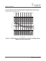
1
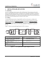
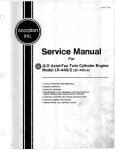
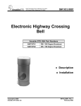
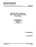
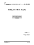
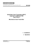
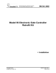
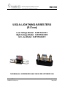
SM 6108
1000 Technology Drive, Pittsburgh, PA 15219
645 Russell Street, Batesburg, SC 29006
USG-A LIGHTNING ARRESTERS
(E-Zvue)
Low Voltage Model: N451552-0101
High Voltage Model: N451552-0201
AC Line Model: N451552-0401
THIS MANUAL SUPERSEDES SM-6108 DATED OCTOBER 1982
©
Copyright 2013
Ansaldo STS USA, Inc.
SM 6108, (Rev. 5/89)
May 1989
Notices
Proprietary Notice
This document and its contents are the property of Ansaldo STS USA,
Inc. (formerly known as Union Switch & Signal Inc., and hereinafter
referred to as "ASTS USA"). This document is furnished to you on the
following conditions: 1.) That no proprietary or intellectual property
right or interest of ASTS USA is given or waived in supplying this
document and its contents to you; and, 2.) That this document and its
contents are not to be used or treated in any manner inconsistent with
the rights of ASTS USA, or to its detriment, and are not to be copied,
reproduced, disclosed or transferred to others, or improperly disposed
of without the prior written consent of ASTS USA.
Important Notice
ASTS USA constantly strives to improve our products and keep our customers apprised of
changes in technology. Following the recommendations contained in the attached service manual
will provide our customers with optimum operational reliability. The data contained herein
purports solely to describe the product, and does not create any warranties.
Within the scope of the attached manual, it is impossible to take into account every eventuality
that may arise with technical equipment in service. Please consult an ASTS USA local sales
representative in the event of any irregularities with our product.
ASTS USA expressly disclaims liability resulting from any improper handling or use of our
equipment, even if these instructions contain no specific indication in this respect. We strongly
recommend that only approved ASTS USA spare parts are used as replacements.
SM 6414, Rev. 1, SM 6108
i
Revision History
Revision History
Rev.
Date
Nature of Revision
Original
October 1982
Original Issue
*
January 1986
N. A.
1
May 1989
N. A.
* Revisions were not numbered, only dated
ii
SM 6108, Rev. 1, May 1989
Table of Contents
1.
2.
3.
4.
5.
6.
7.
Table of Contents
GENERAL INFORMATION .................................................................................................................. 1
1.1. Introduction .................................................................................................................................. 1
PRINCIPLES OF OPERATION ............................................................................................................ 1
2.1. Low Voltage Arrester ................................................................................................................... 1
2.2. High Voltage Arrester .................................................................................................................. 1
2.3. AC Line Arrester .......................................................................................................................... 3
INSTALLATION AND APPLICATION ................................................................................................. 4
3.1. Mounting ...................................................................................................................................... 4
3.2. Wiring ........................................................................................................................................... 4
STATIC SPECIFICATIONS .................................................................................................................. 5
MAINTENANCE ................................................................................................................................... 5
PART NUMBER LIST ........................................................................................................................... 6
RAIL TEAM AND TECHNICAL SUPPORT ......................................................................................... 7
List of Figures
Figure 2-1. Firing Voltage vs. Voltage Rise Rate for USG-A Low Voltage Arrester
(shaded area indicates dispersion) ........................................................................................... 2
Figure 2-2. Firing Voltage vs. Voltage Rise Rate for USG-A High Voltage Arrester
(shaded area indicates dispersion) ........................................................................................... 3
Figure 3-1. AFO System Basic Signal Diagram, End-Fed ........................................................................... 4
List of Tables
Table 4-1. Operating specifications for the USG-A Lightning Arresters ...................................................... 5
SM 6414, Rev. 1, May 1989
iii
Table of Contents
iv
SM 6108, Rev. 1, May 1989
General Information
1. GENERAL INFORMATION
1.1. Introduction
This manual describes the principle of operation, application and testing of the USG-A "E-Zvue"
Lightning Arresters. These include the low voltage, high voltage, and AC line arresters.
These arresters are designed to limit transverse (line to line) and longitudinal (line to ground)
voltage transients to levels below that of equipment destruction. They are provided as standalone
units or mounted on an AAR terminal block
2. PRINCIPLES OF OPERATION
2.1. Low Voltage Arrester
The USG-A Low Voltage Lightning Arrester (N451552-0101) consists of a silicon carbide
varistor ring sandwiched between two brass disks. Electrically, the varistor is in series with the
brass disks but in parallel with the air gap spacing of the brass disks. This is referred to as a
varistor-filled gap arrester. The varistor acts as a non-linear resistor whose resistance gets lower
with more applied voltage. With this behavior, the arrester is quite effective at bleeding off
electrostatic charge and limiting the peak level of surge voltages.
NOTE
The difference between surge and transient is time. Surges are
classically defined as having a duration of greater than 8.3
mseconds and transients less than 8.3 mseconds.
In the transient case, the arrester behaves a little differently. The change of resistance, with
respect to time, becomes slower than the rising level of voltage, with respect to time, which is
seen across the arrester. At some point, this voltage becomes high enough - fast enough to jump
the varistor-filled gap and thus you have an arc-over condition.
For this reason, the static and dynamic breakdown of this or any other varistor-based arrester are
entirely different. The difference is determined by how rapidly the leading edge of the transient
rises. The graph of Figure 2-1 shows the range of expected firing voltages for various transient
rise rates.
2.2. High Voltage Arrester
The USG-A High Voltage Arrester (N451552-0201) is a true air gap arrester. Its construction is
similar to the low voltage arrester with the exception of an added teflon washer which is used to
mechanically hold the gap spacing. The assembly consists of: brass disk - silicon carbide ring teflon washer - brass disk. The varistor-teflon washer provides for a current limited gap in
parallel with the gap set by the physical separation of the brass disks. When exposed to a high
voltage potential, the varistor-teflon gap breaks over. Current is limited by the non-linear, but
resistive action of the varistor material. If the potential rise is rapid enough, the varistor
resistance cannot decrease fast enough or far enough to allow all the energy to be transferred
across its teflon gap. Therefore, the air gap between brass disks breaks down and arc-over
SM 6414, Rev. 1, May 1989
1
Principles of Operation
occurs. As with the low voltage type, the firing voltage will be dependent on the rate of rise of
the leading edge of the transient. The graph of Figure 2-2 shows the range of expected firing
voltages for various transient rise rates.
1000
DC FIRING VOLTAGE
100 V/
sec.
1 kV /
sec.
sec.
200
10 kV/
FIRING VOLTAGE, V (Volts)
500
10 -7
10 -6
100 V/se
c.
100
50
3H2.0004.00
10 -8
10 -5
10 -4
10 -3
10 -2
10 -1
1
10
TIME, t (sec)
Figure 2-1. Firing Voltage vs. Voltage Rise Rate for USG-A Low Voltage Arrester
(shaded area indicates dispersion)
2
SM 6108, Rev. 1, May 1989
Principles of Operation
sec.)
DC FIRING VOLTAGE
(100 V/
sec.)
(100 V/s
ec.)
FIRING VOLTAGE (Volts)
2000
(1 kV/
(10 kV/
sec.)
5000
1000
500
3H2.0005.00
200
10 -8
10 -7
10 -6
10 -5
10 -4
10 -3
10 -2
10 -1
1
10
10 2
TIME (sec)
Figure 2-2. Firing Voltage vs. Voltage Rise Rate for USG-A High Voltage Arrester
(shaded area indicates dispersion)
2.3. AC Line Arrester
The USG-A, AC Line Arrester (N451552-0401) is constructed by stacking five varistor filled
gaps (identical to that of the USG-A Low Voltage Arrester) in series.
SM 6414, Rev. 1, May 1989
3
Installation and Application
3.
INSTALLATION AND APPLICATION
3.1. Mounting
All USG-A Lightning Arresters may be wall or shelf-mounted. Do not mount a unit upside
down, or on the underside of a shelf. The unit may also be mounted horizontally or vertically. If
mounting vertically, position the open end of the cover downwards to prevent accumulation of
dust and moisture inside the cover. Allow one inch minimum clearance between the open end of
the arrester and a flat mounting surface to permit escape of gases.
3.2. Wiring
To obtain maximum protection, wiring should be run first to the arresters, and then to the
equipment. This places the arresters between the exposure and the equipment. The primary
arresters should be kept as far from the equipment as possible and as near to the expected
transient source as possible. The common ground bus should be as short and free of bends as
practical, and should be connected to all housing, signal poles, and grounds at a particular
location.
1
1
4
NOTE
A
3H2.0001.00
AC
POWER
SOURCE
BATTERY
RECTIFIER
16.2 VDC
MAXIMUM
PARTS
1. USG-A Arrester: N451552-0201 (High Voltage)
w/AAR terminal block: X451552-0302 Rated
breakdown: 500-1300 VDC
2. USG-A Arrester: N451552-0101 (Low Voltage)
w/AAR terminal block: X451552-0301 rated
breakdown: 75-200 VDC
3. Surge ripple Filter: N451036-0702 Up to 2.5 amp
load
4. USG-A Arrester: N451552-0401 (AC Line) w/AAR
terminal block: X451552-0306
TWISTED
PAIR
Figure 3-1 shows recommended applications for USG-A Arresters
2
SURGERIPPLE
FILTER
3
NOTE
B
1
EQUIPMENT
TO BE
PROTECTED
2
TRACK
1
NOTES
NOTE A: For 240 VAC operation: two AC Line
Arresters (item 4) in series.
NOTE B: Surge ripple filter should be used if battery
ripple exceeds 5%.
Figure 3-1. AFO System Basic Signal Diagram, End-Fed
4
SM 6108, Rev. 1, May 1989
Static Specifications
4.
STATIC SPECIFICATIONS
Table 4-1 shows the expected static operating and breakover voltages of the Low Voltage, High
Voltage, and AC Line Arresters.
Table 4-1. Operating Specifications for the USG-A Lightning Arresters
Operating Voltages
Breakdown Voltages
Resistance
N451552-0101
32 VDC, 25 VAC
N451552-0201
250 VDC, 175 VAC
N451552-0401
140 VAC
N451552-0101
75-200 VDC, 50-10 VAC (60Hz)
N451552-0201
500-1300 VDC, 350-390 VAC (60 Hz)
N451552-0401
(Not applicable)
N451552-0101
≥ 10 ohms @ 32 VDC
N451552-0201
≥ 10 ohms @ 100 VDC
N451552-0401
≥ 5 x 10 ohms @ 120 VAC
3
9
3
5. MAINTENANCE
The USG-A Lightning Arresters are not serviceable, and must be replaced when faulty. Also, no
attempt should be made to clean an arrester, otherwise carbon-tracking may develop around the
air gap(s). However, an arrester may be given several visual and electrical tests to determine
whether the unit is faulty.
When a USG-A Lighting Arrester has dissipated a surge, the transparent cover may be slightly
burnt or singed around the air gap(s). This does not necessarily indicate a damaged arrester, nor
will it affect the subsequent operation of the arrester.
The resistance of a USG-A Lightning Arrester may be checked with a power source and an
ammeter. The procedure is as follows:
1. Connect power source, ammeter, and arrester in series.
2. Turn on power source and adjust as follows:
32 VDC for unit N451552-0101.
1V00 VDC for unit N451552-0201.
120 AC for unit N451552-0401.
3. The ammeter should read as follows:
Unit N451552-0l01 = less than 32.0 milliamps.
Unit N451552-0201 = less than 0.1 microamps.
Unit N451552-0401 = less than 25.0 milliamps.
SM 6414, Rev. 1, May 1989
5
Part Number List
6. PART NUMBER LIST
See front cover for photos.
Description
Low Voltage USG-A Lightning Arrester, 32 VDC, 25 VAC, blue lettering
High Voltage USG-A Lightning Arrester, 250 VDC, 175 VAC, red lettering
AC Line USG-A Lightning Arrester, 140 VAC, yellow lettering
Low Voltage USG-A Lightning Arrester, mounted on AAR terminal block
High voltage USG-A Lightning Arrester, mounted on AAR terminal block
AC Line USG-A Arrester, mounted on AAR terminal block
6
ASTS USA Part Number
N451552-0101
N451552-0201
N451552-0401
X451552-0301
X451552-0302
X451552-0306
SM 6108, Rev. 1, May 1989
RAIL Team and Technical Support
7.
RAIL TEAM AND TECHNICAL SUPPORT
The Rapid Action Information Link (RAIL) team created in 1996 serves the technical needs of
current and potential ASTS USA customers. Convenient 24-hour access and a rapid resolution to
customer problems are the trademarks of this organization. The RAIL team, which is staffed
primarily by ASTS USA product and application engineers, is ready to assist and resolve
technical issues concerning this or any ASTS USA product.
Direct any questions regarding the contents of this service manual to the RAIL team by
telephone at 1-800-652-7276 or through Internet e-mail at [email protected]..
SM 6414, Rev. 1, May 1989
7
RAIL Team and Technical Support
End of Manual
8
SM 6108, Rev. 1, May 1989