1
Page 12
3p6 M2 CONTROL ELECTRONICS
24 - 06 - 2005
Doc. 3P6-DSD-ESO-60400-0001
Design Document
3
4
6
5
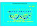
Wire jumper
Open
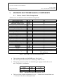
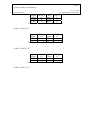
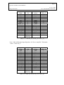
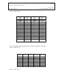
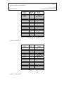
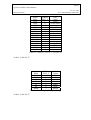
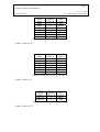
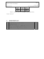
Table 3 : Component Adapter Configuration
4.4. Cabinet Cooling Unit
The cabinet cooling unit used is the ESO standard “VLT Electronic Cabinet Cooling
System” [AP3]. The unit is mounted on the bottom of the cabinet with adequate
clearance around it for the proper air circulation. Two PT100 elements, one mounted
over a heat-sink in the outer wall of the cabinet and the other in contact with the inner
wall of the cabinet, are used by the cooling system for keeping the internal temperature
the same as the exterior and thus avoiding thermal gradients. The heat is removed from
the unit by means of circulating water.
Note that the cooling unit fans are used for blowing air directly over the VME chassis,
due to space limitations no supplemental fan tray is used in the application.
4.5. Mains Power Distribution
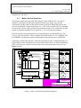
AC power enters the cabinet via a double pole circuit breaker. The control knob of this
breaker is located externally over the side wall of the cabinet. Internally the AC supply
goes to a double contact power relay. The coil of the relay is energized with the mains
supply and serially connected with the catastrophic limit switches chain a thermostat
and a protection fuse. Finally the mains supply goes through an inrush suppressor an
over-voltage protector and a power line filter. The power distribution after the
conditioning is as follows:
¾ Direct connection to the three AC servo amplifiers.
¾ Three Schucko outlets for powering the VME, cooling unit and spare.
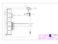
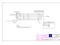
Refer to 7.6 for the schematic diagram.