1
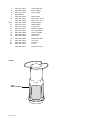
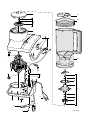
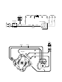
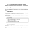
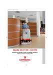
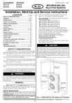
Blender
HR 2849
6000
5000
4000
3000
2000
1000
Philips Domestic Appliances and Personal Care
Product information
Service Information
HR 2845 = Blender with jar
HR 2849 = HR 2845 with HR 2934
Safety device.
The appliance can only be operated if the jar (item 23) is
placed on the body of the appliance so that the safety
interruptor (item 10) located inside the appliance is activated
by means of a shaft (item 9).
Optional:
HR 2924 = Mill
see Service Manual 4822 729 21479
HR 2926 = Chopper see Service Manual 4822 729 21481
HR 2934 = Filter
see Service Manual 4322 277 00070
Type no.:
HR 2845/AM means first version and production centre is
Mexico; HR 2845/AB means first version and production
centre is Brazil.
Safety system
: The blender operates only if the jar,
mill or chopper is correctly placed
on the drive unit.
Safety cap
: The cap locks the lid to the jar in
order to avoid spillage.
Cord storage
: It allows control of the cordset length.
Switch
: 3 speeds with pulse position
in the max position (slide control).
Power consumption : 400 W
Dimensions lxhxw : 18.5 x 38.5 x 17 cm.
Volume jar
: Effective 1.5 and total 2.0 litre.
Cleaning
: Do not clean the parts in a
dishwasher.
Product meets the requirements regarding
interference suppression on radio and TV.
Published by Philips Domestic Appliances and Personal Care
4322 277 00071
02/04
PCS 101 289
Knife assy.
To remove the knife assy (item 17) from the jug (item 23) turn
the knife assy clockwise).
Disassembly of the appliance.
Loosen the two screws to be able to remove the base from
the appliance. Then undo the 3 snap connections which
fasten the base 2 snap connections in the front part and 1
snap connection in the rear part.
Remove the base.
Remove the cover (item 1) of the body (item 3) by undoing its
snap tabs through the 4 openings near the jar coupling.
Drive coupling (item 2) can now be loosened with the help of
a hammer and a screwdriver. Hit the screwdriver with a short
sharp blow of the hammer and remove the drive coupling
clockwise.
Grasp the end of the motor shaft and turn the motor
anticlockwise. Disconnect the motor wires.
Inspection after repair.
Test the safety interruptor by mounting and dismounting the
jar while the appliance is switched on.
Make sure that the speed switch operates properly in all
speed settings.
After the product has been repaired, it should function
properly and has to meet the safety requirements as
laid down officially established at this moment.
Printed in the Netherlands
© Copyright reserved
Subject to modification
1
2
3
4
7
4822 441 31341
4822 690 40302
4822 441 31364
Not available
4822 532 61264
Cover drive unit
Fan coupling
Top housing
8
9+10
10
12
4822 361 30444
4822 361 30448
4822 276 13585
4822 277 21774
4822 441 31345
Motor 220 - 230 V
Motor 120 - 127 V
Safety system
Safety switch
Lower cover
13
14
15
16
17
4822 441 31347
4822 321 10364
4822 528 20789
4822 532 52643
4822 690 40299
Bottom housing
Flex (standard)
Driven coupling
Sealing ring
Knife unit
18
21
22
23
4822 273 10293
4822 441 31335
4822 441 31334
4822 418 40975
Switch and wires
Cap of jar
Lid of jar
Cil. jar
-
4222 000 87410
Direction for use
HR 2934
Filter
4206 136 49450
PCS 101 290
Motor buffer
1
21
22
2
3
18
7
23
8
7
9
16
17
14
15
13
10
4
12
A
DAP 0157
A
3 Pos. Switch
High
50-60 Hz
Mid
Green
white
Low
Safety
System
Pulse
blue
MOTOR
4
Off
brown
yellow
6
green
7
8
white
3
1
9
2
3
2
1
10
11
12
18
17
16
white
13
15
3
P
6
1
yellow
Connector
housing
2
blue
18
brown
9
white
11