1
Notice
Hewlett-Packard to Agilent Technologies Transition
This documentation supports a product that previously shipped under the HewlettPackard company brand name. The brand name has now been changed to Agilent
Technologies. The two products are functionally identical, only our name has changed. The
document still includes references to Hewlett-Packard products, some of which have been
transitioned to Agilent Technologies.
Printed in USA
March 2000
HP 11757B
Multipath Fading Simulator
Operation and Programming
SERIAL NUMBERS
Attached to the rear panel of the instrument is a
serial number plate. The serial number is in the form:
0000A00000. The rst four digits and the letter are
the serial number prex. The last ve digits are the
sux. The prex is the same for identical instruments; it
changes only when a conguration change is made to the
instrument. The sux, however, is assigned sequentially
and is dierent for each instrument.
This manual applies to instruments with serial numbers
prexed 3606U and above.
ABCDE
HP Part No. 11757-90059
c HEWLETT-PACKARD COMPANY 1992,1993,1996,1998
Station Road, South Queensferry, Scotland, EH30 9TG, UK
Printed in UK
Contents
1. General Information
Description . . . . . . . . . . . . .
DRTS . . . . . . . . . . . . . . .
IF Bands . . . . . . . . . . . . .
Option 001 . . . . . . . . . . . .
Connecting the HP 11757B to a BERT
Documentation . . . . . . . . . . . .
Safety Considerations . . . . . . . .
Instruments Covered by this Manual .
Specications . . . . . . . . . . . .
Options . . . . . . . . . . . . . . .
2. Detailed Operating Instructions
Detailed Operating Instructions . . .
Arrows . . . . . . . . . . . . . .
ATTEN . . . . . . . . . . . . . .
Automatic Gain Control (AGC) . . .
BACK SP . . . . . . . . . . . . .
DATA ENTRY . . . . . . . . . . .
DELAY . . . . . . . . . . . . . .
Display . . . . . . . . . . . . . .
ENTER . . . . . . . . . . . . . .
EXIT . . . . . . . . . . . . . . .
Fade Event . . . . . . . . . . . .
Fast Programming of Notch Parameters
(Remote Only) . . . . . . . . .
HP-IB ADDRESS . . . . . . . . .
INIT . . . . . . . . . . . . . . .
MEAS . . . . . . . . . . . . . .
MEAS SETUP . . . . . . . . . . .
1-1
1-1
1-2
1-2
1-2
1-4
1-5
1-5
1-5
1-6
.
.
.
.
.
.
.
.
.
.
.
2-1
2-2
2-3
2-6
2-10
2-11
2-12
2-13
2-14
2-16
2-17
.
.
.
.
.
2-25
2-27
2-28
2-29
2-32
Contents-1
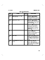
MEAS TYPE . . . . . . . .
MORE . . . . . . . . . . .
NOTCH DEPTH . . . . . . .
NOTCH FREQ . . . . . . .
PHASE . . . . . . . . . . .
PRESET/LOCAL . . . . . .
PRINTER . . . . . . . . . .
RADIO SETUP . . . . . . .
RECALL . . . . . . . . . .
SAVE . . . . . . . . . . . .
SELF TEST . . . . . . . . .
Service Mode . . . . . . . .
SET YMD (date) . . . . . . .
SET HMS (MORE function 10)
SET START . . . . . . . . .
SET STOP . . . . . . . . .
SET TIME . . . . . . . . .
Single Sweep . . . . . . . . .
SLEW TIME . . . . . . . .
SLOPES . . . . . . . . . .
SWEEP ALL . . . . . . . .
SWEEP ATTEN . . . . . . .
SWEEP DEPTH . . . . . . .
SWEEP FREQ . . . . . . . .
SWEEP ON/OFFs . . . . . .
SYNCHRONIZATION . . . .
TEST MASK . . . . . . . .
.
.
.
.
.
.
.
.
.
.
.
.
.
.
.
.
.
.
.
.
.
.
.
.
.
.
.
.
.
.
.
.
.
.
.
.
.
.
.
.
.
.
.
.
.
.
.
.
.
.
.
.
.
.
.
.
.
.
.
.
.
.
.
.
.
.
.
.
.
.
.
.
.
.
.
.
.
.
.
.
.
.
.
.
.
.
.
.
.
.
.
.
.
.
.
.
.
.
.
.
.
.
.
.
.
.
.
.
3. Introduction to Remote Programming of HP
11757B
SCPI . . . . . . . . . . . . . . .
Controllers Other Than Hewlett-Packard
Programming and Documentation
Conventions . . . . . . . . . . .
Notation Conventions and Denitions .
Command Structure . . . . . . . .
Contents-2
2-39
2-50
2-52
2-54
2-56
2-59
2-62
2-65
2-68
2-70
2-72
2-75
2-76
2-77
2-78
2-80
2-82
2-83
2-84
2-85
2-87
2-88
2-90
2-92
2-94
2-96
2-99
3-1
3-1
3-3
3-3
3-4
4. Common Commands
Introduction . . . . . . . . . . . . .
*CLS (Clear Status Command) . . . .
*ESE (Standard Event Status Enable)
*ESR? (Standard Event Status Register
Query) . . . . . . . . . . . . .
*IDN? (Identication Query) . . . . .
*IST? (Individual Status Query) . . .
*LRN? (Learn Device Setup Query) . .
*OPC (Operation Complete) . . . . .
*OPT? (Option Identication Query) .
*PRE (Parallel Poll Enable Register) .
*RCL (Recall Command) . . . . . .
*RST (Reset Command) . . . . . .
*SAV (Save Command) . . . . . . .
*SRE (Service Request Enable) . . . .
*STB? (Read Status Byte Query) . .
*TRG (Trigger Command) . . . . . .
*TST? (Self-Test Query) . . . . . .
*WAI (Wait-to-Continue Command) .
4-1
4-4
4-6
4-9
4-12
4-14
4-16
4-18
4-20
4-22
4-24
4-25
4-28
4-29
4-31
4-34
4-35
4-36
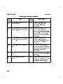
5. Subsystem Commands
POWer:AGC(Enable Disable AGC) . . .
5-2
POWer:AGC:BANDwidth
(Set Bandwidth of Input Signal) . . .
5-3
POWer:AGC:FREQuency:CENTer
(Set AGC Center Frequency of Input Signal) 5-4
POWer:ATTenuation (Set Attenuation) .
5-5
POWer:ATTenuation:MODE
(Set Sweep Mode for Attenuation) . .
5-6
POWer:ATTenuation:STARt
(Set Start Attenuation) . . . . . . .
5-7
POWer:ATTenuation:STOP
(Set Stop Attenuation) . . . . . . .
5-8
POWer:DEPTh(Set Fixed Notch Depth) .
5-9
POWer:DEPTh:DELay (Set Delay Time)
5-10
POWer:DEPTh:MODE (Set Sweep Mode) 5-11
POWer:DEPTh:PHASe (Set Notch Phase) 5-12
Contents-3
POWer:DEPTh:SLOPes
(Set In-Band Gain Slope) . . . . . . 5-13
POWer:DEPTh:STARt
(Set Start Notch Depth) . . . . . . 5-14
POWer:DEPTh:STARt:PHASe
(Set Start Notch Phase) . . . . . . 5-15
POWer:DEPTh:STOP
(Set Stop Notch Depth) . . . . . . 5-16
POWer:DEPTh:STOP:PHASe
(Set Stop Notch Phase) . . . . . . 5-17
FREQuency(Set Notch Frequency) . . . 5-18
FREQuency:MODE
(Set Sweep Mode for Notch Frequency) 5-19
FREQuency:RATE:STARt
(Set Freq Start Rate for Dynamic-S Meas) 5-20
FREQuency:RATE:STOP
(Set Freq Stop Rate for Dynamic-S Meas) 5-21
FREQuency:STARt(Set Start Frequency) 5-22
FREQuency:STOP(Set Stop Frequency) . 5-23
SWEep:ALL
(Control Sweep Mode for All Sweeps)
5-24
SWEep:TIME (Set Sweep Time) . . . . 5-25
SWEep:SLEW (Set Slew Time) . . . . 5-26
SWEep:SLEW:RATE
(Set Maximum Slew Rate) . . . . . 5-27
SWEep:MODE(Set Single Sweep Mode) . 5-28
Description of LIST Subsystem . . . . . 5-29
LIST:FREQuency
(Enter Frequency Values into Fade Prole Table) 5-32
LIST:POWer:ATTenuation
(Enter Attenuation Values into Fade Prole Table) 5-34
LIST:POWer:DEPTh
(Enter Depth Values into Fade Prole Table) 5-36
LIST:POWer:DEPTh:PHASe
(Enter Phase Values into Fade Prole Table) 5-38
LIST:PRESet(Preset Fade Prole Table)
5-40
LIST:SSEQuencen
(Set Start/Stop Indexes for Fade Events) 5-41
Contents-4
LIST:TIME
(Enter Time Values into Fade Prole Table) 5-42
LIST:UPDate
(Set Editing Mode for Fade Prole Table) 5-44
5. Subsystem Commands
TRIGger:SOURce
(Set Trigger Source for Fader) . . . . 5-45
TRIGger2:BER(Set BER Threshhold) . . 5-46
TRIGger2:BER:ECOunt
(Set BER Accuracy) . . . . . . . . 5-47
TRIGger2:BER:FREQuency
(Set Radio Bit Rate) . . . . . . . . 5-48
TRIGger2:BER:MULTiplier
(Scale Incoming Errors) . . . . . . 5-49
TRIGger2:BER:SYMBol:TIME
(Set Radio Symbol Time) . . . . . . 5-50
TRIGger2:ECL
(ERROR PULSE INPUT to ECL) . . 5-51
TRIGger2:LEVel
(Set ERROR PULSE Threshold) . . 5-52
TRIGger2:TTL
(ERROR PULSE INPUT to TTL) . . 5-53
TRIGger2:TIMer(Set Radio Wait Time) . 5-54
ERRor:COUPling
(Set Coupling for ERROR PULSE INPUT) 5-55
ERRor:IMPedance
(Set Input Impedance for ERROR PULSE INPUT) 5
ALARm:COUPling?
(Query the Coupling of ALARM INPUT) 5-57
ALARm:IMPedance?
(Query the Input Impedance of ALARM INPUT) 5-5
ALARm:POLarity
(Set Polarity of the ALARM Input) . 5-59
FM:DEViation
(Set Frequency Deviation for Dynamic-M) 5-60
FM:INTernal:RATE
(Set Frequency Rate for Dynamic-M)
5-61
Contents-5
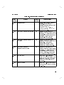
5. Subsystem Commands
CALCulate:SMOothing:STATe
(Enable/Disable EDGE ZOOM) . . .
Test Mask Overview . . . . . . . . .
CALCulate:LIMit:STATe
(Turn Test Mask On/O) . . . . .
CALCulate:LIMit:CONTrol:MINimum
(Load Test Mask \x" Min Data) . . .
CALCulate:LIMit:CONTrol:NONMinimum
(Load Test Mask Nonmin \x" Data) .
CALCulate:LIMit:LOWer:MINimum
(Load Test Mask Min \y" Data) . . .
CALCulate:LIMit:LOWer:NONMinimum
(Load Test Mask Nonmin \y" Data) .
CALCulate:LIMit:FAIL?
(Reports Test Mask Pass/Fail) . . .
CALCulate:LIMit:FCOunt?
(Report Number of Test Mask Fails) .
CONFigure:ARRay:DYNamic:FM
(Congure Dynamic-M Measurement)
CONFigure:ARRay:DYNamic:SWEep
(Congure Dynamic-S Measurement) .
CONFigure:ARRay:HYSTeresis
(Congure Hysteresis M-Curve Meas)
CONFigure:ARRay:STATic
(Congure Static-M Measurement) . .
CONFigure:RECovery
(Congure Recovery Time Measurement)
CONFigure:BER
(Congure BER Measurement) . . .
INITiate . . . . . . . . . . . . . . .
FETCh?(Download Last Measured Data)
FETCh:DFM?
(Download Dispersive Fade Margin) .
Contents-6
5-63
5-64
5-66
5-67
5-68
5-69
5-70
5-71
5-72
5-73
5-75
5-77
5-79
5-81
5-82
5-83
5-84
5-86
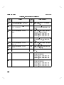
5. HP-IB Commands
SYSTem:COMMunicate:GPIB:ADDRess
(Set HP-IB Address) . . . . . . . .
5-87
SYSTem:COMMunicate:PRINter:DESTination
(Select Printout Destination) . . . . 5-88
SYSTem:COMMunicate:PRINter:DUMP
(Print Measurement Information) . . 5-89
SYSTem:COMMunicate:PRINter:STATe
(Enable/Disable Printer Output) . . 5-91
SYSTem:DATE (Set the Date) . . . . . 5-92
SYSTem:ERRor?(Read Error Queue) . . 5-94
SYSTem:KEY(Press Front Panel Key) . 5-96
SYSTem:TIME(Set the Clock Time) . . 5-100
SYSTem:VERSion?(Read SCPI Version) . 5-102
STATus:OPERation:CONDition?
(Read Operation Condition Register) 5-103
STATus:OPERation:ENABle
(Operation Event Enable Register) . . 5-106
STATus:OPERation?
(Read Operation Event Register) . . 5-109
STATus:OPERation:NTRansition
(Operation Negative Transition Reg) . 5-112
STATus:OPERation:PTRansition
(Operation Positive Transition Reg) . 5-115
STATus:PRESet(Preset STATus Registers) 5-118
STATus:QUEStionable:CONDition?
(Read Questionable Condition Register) 5-120
STATus:QUEStionable:ENABle
(Questionable Event Enable Register) 5-123
STATus:QUEStionable?
(Read Questionable Event Register) . 5-126
STATus:QUEStionable:NTRansition
(Questionable Negative Transition Reg) 5-129
STATus:QUEStionable:PTRansition
(Questionable Positive Transition Register) 5-132
DISPlay(Enable/Disable Display) . . . . 5-135
Contents-7
A. Error Messages
Description . . . . . .
HP-IB Output Format
Example . . . . . . .
Status Reporting . . .
Error Messages . . . .
.
.
.
.
.
.
.
.
.
.
.
.
.
.
.
.
.
.
.
.
.
.
.
.
.
.
.
.
.
.
.
.
.
.
.
A-1
A-1
A-1
A-2
A-2
Introduction . . . . . . . . . . . .
SCPI Measurement System Overview
Using MEASure:function ? . . . . .
Using READ:function ? . . . . . .
Using FETCh:function ? . . . . . .
.
.
.
.
.
C-1
C-3
C-9
C-14
C-19
.
.
.
.
.
.
.
D-1
D-2
D-12
D-16
D-17
D-18
D-22
B. Specications
C. Advanced HP-IB Measurements
D. HP-IB Compliance
Introduction . . . . . . . . . . . .
SCPI Conformance Information . .
Avoiding Fader Interruptions . . . .
Interface Functions . . . . . . . .
Status Annunciators . . . . . . .
IEEE 488.2 Compliance Information
Related Documents . . . . . . . .
Index
Contents-8
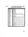
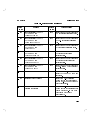
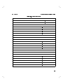
Figures
1-1.
2-1.
2-2.
2-3.
2-4.
2-5.
2-6.
2-7.
2-8.
2-9.
5-1.
HP 11757B Documentation . .
Speed and Deviation . . . . .
Edge Zoom . . . . . . . . .
Typical M-Curve Output . . .
Static M-Curve Measurement .
Hysteresis-M Measurement . . .
Dynamic M-Curve Measurement
Dynamic S-Curve Measurement
Dynamic S-Curve Measurement
Test Mask Interpolation . . . .
Fade Prole Table . . . . . .
.
.
.
.
.
.
.
.
.
.
.
.
.
.
.
.
.
.
.
.
.
.
.
1-4
. 2-36
. 2-37
. 2-40
. 2-41
. 2-42
. 2-43
. 2-45
. 2-46
. 2-100
. 5-29
Contents-9
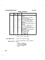
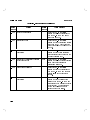
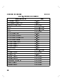
Tables
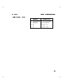
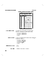
1-1.
4-1.
4-2.
4-3.
4-4.
4-5.
4-6.
4-7.
4-8.
A-1.
B-1.
B-2.
C-1.
Recommended Cables . . . . . . . .
Fader IEEE 488.2 Common Commands
Standard Event Status Enable Register
Standard Event Status Register . . .
*OPT? Fader Option Numbers . . . .
Parallel Poll Enable Register . . . . .
Preset Values . . . . . . . . . . .
Service Request Enable Register . . .
The Status Byte . . . . . . . . . .
Error Messages . . . . . . . . . . .
Specications . . . . . . . . . . .
Supplemental Characteristics . . . . .
CONFigure:function and
MEASure:function ? Parameters . .
C-2. FETCh:function ? and READ:function ?
Parameters . . . . . . . . . . .
D-1. SCPI Conformance . . . . . . . . .
Contents-10
1-6
4-3
4-7
4-10
4-20
4-23
4-25
4-30
4-32
A-3
B-2
B-4
C-3
C-4
D-3
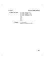
1
General Information
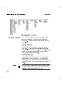
This volume provides dictionary style reference material
for the HP 11757B Multipath Fading Simulator. This
includes:
Descriptions of all front panel keys and functions,
organized alphabetically.
HP-IB Reference, including:
Introduction to Remote Programming
Common Commands
Root and Subsystem HP-IB Commands
Appendix A Error Messages
Appendix B Specications
Appendix C Advanced HP-IB Measurements
Appendix D HP-IB Compliance
Index
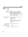
Description
DRTS
If your Fader is an integral part of a HP 11758T/U
Digital Radio Test Set (DRTS) this manual also applies
with a few exceptions. There is no internal printer in
the DRTS, so commands relating to the internal printer
must be disregarded. There are also no numeric keys 4 5
through 4 5, so parameters must be entered using arrow
keys.
0
9
1-1
General Information
IF Bands
Option 001
HP 11757B
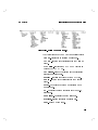
The HP 11757B has options on two IF bands. The
options available are:
Standard: 40 MHz to 100 MHz
Option 140: 90.0 MHz to 190.0 MHz
Option 147: 40 MHz to 100 MHz and 90.0 MHz to
190.0 MHz
Serial prexes less than 3215A have an upper band range
of 110.0 MHz to 170.0 MHz.
If your HP 11757B is an option 001, it does not
have built in signature analysis. You cannot select a
measurement type such as Static M or Dynamic S. All
instructions in this manual pertaining to signatures,
4
5, 4
5, 4
5 and 4
5
do not apply to option 001 instruments. To perform
M-Curves or other signature measurements with option
001, you must either perform them manually, or use an
external controller and program.
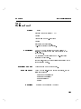
MEAS
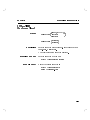
Connecting the HP
11757B to a BERT
MEAS TYPE
RADIO SETUP
MEAS SETUP
The HP 11757B can work with many dierent types of
Bit Error Rate Testers (BERT). However, not all BERTs
operate the same way and it is important for you to
understand how to correctly interface dierent types of
BERTS to the HP 11757B.
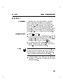
Triggering
The 4
5 key can be used to adjust the triggering
of the ERROR PULSE INPUT and ALARM INPUT
connectors to coincide with the BERT you are using.
The ERROR PULSE INPUT line can be terminated
in ECL/75
, TTL/75
, or TTL/ 10k
. In addition,
an ERROR PULSE INPUT variable threshold can be
selected instead of ECL or TTL thresholds. ERROR
PULSE INPUT variable threshold is only available in
serial prexes 3235A and above. The HP 11757B will
Radio Setup
1-2
HP 11757B
General Information
always trigger on the rising edge of signals applied to the
\ERROR PULSE IN" connector.
The ALARM INPUT connector is always terminated
in TTL/10k
. However, the edge (positive or negative
going) that the Fader triggers on can be chosen by you.
Select the one that works with your BERT.
Error Pulse Signals during Out-of-Lock Situations
It is very important to understand what kind of
\ERROR PULSE" signal your BERT puts out when
the radio is out-of-lock. Ideally, when the radio is
out-of-lock, the BERT will put out a very fast stream
of pulses indicating a very high Bit Error Rate (BER).
If this is the case with your BERT, all you need do for
BER Criteria measurements is connect the \ERROR
PULSE" of your BERT to the ERROR PULSE INPUT
connector on the front panel of the Fader.
On the other hand, some BERTs turn o their \ERROR
PULSE" signal when an out-of-lock state is detected.
If this is the case with your BERT, you not only need
to connect the \ERROR PULSE" of the BERT to the
ERROR PULSE INPUT of the Fader, you must also
connect an Alarm line from either your radio or your
BERT to the ALARM INPUT line of the Fader. This
is because when no errors are present on the ERROR
PULSE INPUT line, the Fader cannot tell the dierence
between an out-of-lock situation and one were the bit
error rate is truly zero. The Fader needs the ALARM
INPUT line to determine which of these situations is
occurring.
1-3
General Information
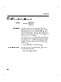
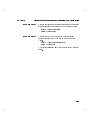
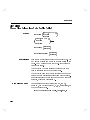
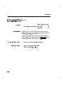
Documentation
HP 11757B
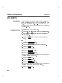
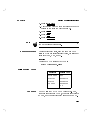
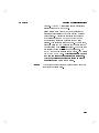
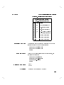
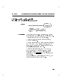
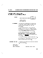
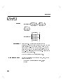
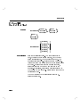
Four other manuals make up the documentation set for
the HP 11757B. They are:
Installation and Calibration. This manual contains
information needed to install, verify and calibrate the
HP 11757B. It is shipped inside the binder for the
User's Guide
Making Measurements with the HP 11757B Multipath
Fading Simulator. This manual contains detailed
instructions for making specic measurements with the
Fader. This manual is also shipped inside the binder
with the User's Guide.
Beginner's Guide to SCPI This guide provides the
elementary concepts you must know before you can
program instruments that implement the Standard
Commands for Programmable Instruments (SCPI).
SCPI was formerly known as TMSL. This manual is
also shipped with the User's Guide.
Service Manual. This manual contains procedures
needed for assembly level troubleshooting,
adjustments, and servicing of the Fader.
Figure 1-1. HP 11757B Documentation
1-4
HP 11757B
Safety Considerations
Instruments Covered
by this Manual
Specifications
General Information
This product is a Safety Class I instrument, that is, one
provided with a protective earth terminal. The Fader
and all related documentation should be reviewed for
familiarization with safety markings and instructions
before operation. Refer to the \Safety Considerations"
page found at the beginning of this manual for a
summary of the safety information. Safety information
for installation, operation, and performance testing is
found in Installation and Calibration Manual.
Attached to the rear panel of the instrument is a
serial number plate. The serial number is in the form:
0000A00000. The rst four digits and the letter are
the serial number prex. The last ve digits are the
sux. The prex is the same for identical instruments; it
changes only when a conguration change is made to the
instrument. The sux however, is assigned sequentially
and is dierent for each instrument. The contents of this
manual apply directly to instruments having the serial
number prex(es) listed under \Serial Numbers" on the
title page.
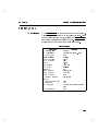
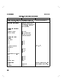
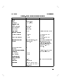
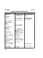
Instrument specications are listed in appendix B.
These specications are the performance standards or
limits against which the instrument may be tested.
Supplemental characteristics are also listed in appendix
B. Supplemental characteristics are not warranted
specications, but are typical characteristics included as
additional information for the user.
1-5
General Information
HP 11757B
Options
Electrical Options
Option 001, no signature capability. Equivalent to HP
11757A.
Option 140, 90 MHz to 190 MHz
Option 147, 40 MHz to 100 MHz, and 110 MHz to 170
MHz
Serial prexes less than 3215A have an upper band range
of 110.0 MHz to 170.0 MHz.
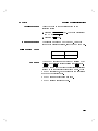
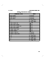
Cables and Accessories
Table 1-1. Recommended Cables
Accessory
Part Number
75
5.5 ft BNC
Synchronization Cable
HP 8120-3616
HP 11757-60027
50
to 75
Adapter
HP 11694
1-6
Use
IF and RF Input
One required per pair of
instruments for
synchronization
Three required per
instrument
2
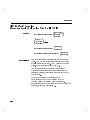
Detailed Operating Instructions
Detailed Operating
Instructions
The Detailed Operating Instructions describe the keys,
functions and features of the HP 11757B Multipath
Fading Simulator. Appearing in alphabetical order below
is a list of Detailed Operating Instructions and the page
numbers where their respective descriptions are found.
2-1
Detailed Operating Instructions
HP 11757B
Arrows
Description
The arrow keys (485, 495, 465, 475) are used to modify
numeric data that is to be entered into the Fader. When
one of the function keys is pressed, a numeric string is
displayed with one blinking digit. The 485 and 495 keys
are used to modify the blinking digit. The 465 and 475
keys are used to move to other digits.
The arrow keys have two functions when the Fader is in
MORE functions mode: 1)to move from one function to
the next the 485 and 495 keys may be used, and 2)when a
function has been selected by the 4
5 key, the arrow
keys are used to change the values of the parameters
displayed.
ENTER
Local Procedure
When entering numeric data into the Fader, use 485 and
to modify the display's blinking digit. Use 465 and 475
to move to other digits of the parameter.
1. Press 4
5, then 4
5
2. Press 4 5, then 4
5
3. Press 485 485 485 485
4. The display should read \4 AGC BW"
5. Press 4
5 to select.
6. The display should read \AGC BW 30.0MZ" The tens
digit should be ashing. To set the bandwidth to 20
MHz:
7. Press 465, then 495
8. Press 4
5 to set the parameter to 20 MHz and
leave the MORE functions display mode.
495
PRESET/LOCAL
SHIFT
ENTER
PRESET/LOCAL
ENTER
ENTER
Remote Procedure
2-2
There is no remote procedure for arrow keys.
HP 11757B
Detailed Operating Instructions
ATTEN
Description
Local Procedure
The 4
5 key allows you to set at fade
gain/attenuation. The attenuation can be set from 0 to
50 dB. The resolution is 0.1 dB. Attenuation may be
swept.
ATTEN
Non Swept
1. Press the 4
5 key.
2. Enter the appropriate attenuation using the data
entry keys.
3. Press the 4
5 key when the value is correct.
or
4. Press the 4
5 key.
5. Use 485 and 495 to modify the blinking digit.
6. Use 465 and 475 to move to other digits.
7. Press the 4
5 key when the ATTEN display reads
the correct value.
ATTEN
ENTER
ATTEN
ENTER
Swept
To sweep attenuation we set start and stop attenuations.
The sweep time will be the same as the sweep time set
for 4
5 and 4
5. It is possible to
sweep only attenuation, but it is not possible to sweep it
at a dierent rate than one set for another parameter.
1. Press the 4
5 key.
2. Press the 4
5 key.
3. Use the arrow keys or the data entry keys to set a
value for the start attenuation.
4. Press the 4
5 key.
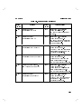
NOTCH FREQ
NOTCH DEPTH
SET START
ATTEN
ENTER
2-3
Detailed Operating Instructions
HP 11757B
5. Press the 4
5 key.
6. Press the 4
5 key.
7. Use the arrow keys or the data entry keys to set a
value for the stop attenuation.
8. Press the 4
5 key.
9. Activate the ATTEN SWP by pressing 4 5, then
4
5.
SET STOP
ATTEN
ENTER
SHIFT
ATTEN
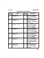
Remote Procedure
The program code for attenuation is POW:ATT. To set
the attenuation to a value, use POW:ATT followed by
the value and DB.
Example
To enter an attenuation of 33.3 dB:
OUTPUT 714;"POW:ATT 33.3DB"
To enter attenuation sweep parameters for start and
stop:
OUTPUT 714;"POW:ATT:STAR 10.0DB"
OUTPUT 714;"POW:ATT:STOP 35.0DB"
To start the attenuation sweep:
OUTPUT 714;"POW:ATT:MODE SWE"
HP-IB Program Codes
Keystroke
ATTEN
SET START
SET STOP
SWP ATTEN
2-4
Program Codes
POW:ATT
POW:ATT:STAR
POW:ATT:STOP
POW:ATT:MODE SWE
HP 11757B
Detailed Operating Instructions
Comments
The preset value of attenuation is 0.0 dB. The preset
start and stop sweep values for attenuation are set to 0,
and the sweep is o.
The 4
5 and 4
5 functions will prompt
you for parameters for NOTCH FREQ, NOTCH
DEPTH and ATTEN consecutively without pressing
the keys for those functions. For instance, if you press
4
5 you will notice a blinking digit in the notch
frequency eld of the display. After you change the value
and press 4
5, you will notice the tens digit blinking
in the notch depth eld. After entering a value for notch
depth, the tens digit in the attenuation eld will blink.
After you have entered a value for a starting attenuation,
the fader will return to the settings displayed before you
changed the set start parameters.
SET START
SET STOP
SET START
ENTER
Note
By entering negative values of attenuation you can get
gain of up to 12 dB. Use the minus sign to signify gain
when entering values.
2-5
Detailed Operating Instructions
HP 11757B
Automatic Gain Control (AGC)
Description
The Automatic Gain Control function provides constant
power gain from the fader input to output, integrated
over a user specied bandwidth. When turned on, the
AGC function will set the fader to 0 dB power gain,
regardless of notch position or depth. The AGC function
is necessary when the fader is inserted after the AGC
amplier in a digital radio.
To set up the AGC function, it is necessary to 4
5
the radio's intermediate frequency (i.e. 70 MHz), as well
as the bandwidth of the radio. These two entries tell the
fader over what frequency range to maintain a constant
power gain. Once these two entries are dened, the AGC
function may be turned on and o without re-entering
the center frequency or bandwidth information. All AGC
information is stored in battery- backed up RAM.
ENTER
Local Procedure
1. Setup the AGC center frequency. This is usually the
center frequency of the digital radio (i.e. 70 MHz or
140 MHz).
a. Press 4 5, then 4
5 to enter the
MORE mode. AGC can also be accessed by
pressing the 4
5 key and using 485 until
AGC functions appear.
b. Use the 485 and 495 arrows until the display shows
\3 AGC FREQ", then press 4
5.
c. The display will change to \AGC FRQ 070.0". Use
the 485 and 495 arrows (or numeric keypad) to
select the desired center frequency. Press 4
5.
2. Setup the AGC bandwidth. This is the bandwidth
over which the fader will keep a constant power gain.
This is usually the bandwidth of the digital radio's
SHIFT
PRESET/LOCAL
RADIO SETUP
ENTER
ENTER
2-6
HP 11757B
Detailed Operating Instructions
intermediate frequency (i.e. 20 MHz bandwidth for a
particular 70 MHz IF radio).
a. Press 4 5, then 4
5 to enter the
MORE mode.
b. Use the 485 and 495 arrows until the display shows
\4 AGC BW". Press 4
5.
c. The display will change to \AGC BW 20.0MZ". Use
the 485 and 495 arrows (or numeric keypad) to
select the desired bandwidth. Press 4
5.
3. Turn on the AGC function. When AGC is on, the
display annunciator over the \AGC" label will be on.
a. Press 4 5, then 4
5 to enter the
MORE mode.
b. Use the 485 and 495 arrows until the display shows
\2 AGC ON/OFF". Press 4
5.
c. The display will change to \AGC OFF". Use the 485
and 495 arrows to change to \AGC ON". Press
ENTER.
Determining the appropriate BW setting for the AGC
function can be done quickly using a power meter and
the IF signal to be faded.
1. Connect the IF signal of your radio to the IF Input of
the Fader.
2. Connect a power meter to the IF Output of the
Fader.
3. Set notch depth on the Fader to 0.0 dB. Measure the
power level at the IF Output.
3. Set notch depth on the Fader to 20.0 dB. Measure the
power level at the IF Output.
4. Adjust the AGC BW setting on the Fader until
the power level at 20.0 dB equals the power level you
measured at 0 dB.
SHIFT
PRESET/LOCAL
ENTER
ENTER
SHIFT
PRESET/LOCAL
ENTER
Note
2-7
Detailed Operating Instructions
HP 11757B
The resultant BW setting will approximate the
integrated noise-power BW of the ltered signal, and
will minimize average power uctuations that would
otherwise result from changes in notch depth and
frequency.
Comments
Remote Procedure
Once the AGC center frequency and AGC bandwidth
have been entered, AGC ON/OFF is the only function
which need be used until either the center frequency or
bandwidth needs to be changed.
To enter the AGC frequency in remote mode, send the
\POW:AGC:FREQ:CENT" command followed by the
AGC frequency.
To enter the AGC bandwidth in remote mode, send the
\POW:AGC:BAND" command followed by the AGC
bandwidth.
To turn the AGC on or o in remote mode, send the
\POW:AGC" command followed by \ON" or \OFF".
Example
To turn on the AGC for a 70 MHz IF radio with a 25
MHz bandwidth:
OUTPUT 714;"POW:AGC:FREQ:CENT 70MHZ"
OUTPUT 714;"POW:AGC:BAND 25MHZ"
OUTPUT 714;"POW:AGC ON"
2-8
HP 11757B
Detailed Operating Instructions
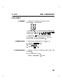
HP-IB Program Codes
Parameter
Program Codes
AGC center frequency
AGC bandwidth
AGC on
AGC o
POW:AGC:FREQ:CENT
POW:AGC:BAND
POW:AGC ON
POW:AGC OFF
2-9
Detailed Operating Instructions
HP 11757B
BACK SP
Description
The 4
5 key allows you to back space over an
incorrect data entry so that you may enter another value
before pressing the 4
5 key.
BACK SP
ENTER
Local Procedure
To use the back space simply press it until the digit you
wish to correct disappears.
Example
Let's use 4
5 to correct an entry in attenuation.
1. Press the 4
5 key.
2. Press the following keys: 4 5 4 5 4 5 4 5
Suppose you meant to enter 13.3 instead.
3. Press 4
5 4
5 4
5
4. Press 4 5 4 5 4 5
5. Press 4
5.
BACK SP
ATTEN
1
BACK SP
3
.
BACK SP
2
.
3
BACK SP
3
ENTER
Remote Procedure
Comments
Back space is not available in remote mode.
If you back space over all the entries in the current
parameter, the setting that existed before you started
data entry appears. For instance, if you had a setting of
40.0 and keystroked in 30.0 without pressing 4
5,
pressing 4
5 four times would produce a reading of
40.0.
ENTER
BACK SP
2-10
HP 11757B
Detailed Operating Instructions
DATA ENTRY
Description
The data entry keys allow numeric entry of all
parameters. The keys include:
475
445
415
405
485
455
425
4.5
495
465
435
4 5
0
The minus sign (0) may be entered either before or after
typing in numbers. For instance, 405 4 5 4 5 4 5 4 5 4
5
yields the same result as 4 5 4 5 4 5 4 5 405 4
5.
4
4
0
.
0
0
.
0
ENTER
ENTER
The decimal key 4 5 allows you to enter tenths and
hundredths. You may enter tenths of a megahertz,
tenths of a dB or tenths of nanosecond.
.
Local Procedure
To enter a notch center frequency of 75.1 MHz:
1. Press the 4
5 key.
2. Press 4 5 4 5 4 5 4 5
3. Press the 4
5 key.
NOTCH FREQ
7
5
.
1
ENTER
Remote Procedure
The program codes for the data are the same as the data
themselves.
Set an attenuation of 10 dB.
OUTPUT 714;"POW:ATT 10.0 DB"
2-11
Detailed Operating Instructions
HP 11757B
DELAY
Description
Local Procedure
The DELAY function (4 5 4
5) allows simulation
of various interpath delays. You simply enter a value,
which is assumed to be in nanoseconds, and the
instrument calculates the correct values for attenuation,
notch depth, and notch frequency to simulate the delay.
The range for delay is 2 ns to 25 ns in steps of 0.1 ns.
SHIFT
PHASE
To set a delay of 5 nanoseconds:
1. Press 4 5, then 4
5.
2. Press 4 5 4 5 4 5 or use the arrow keys.
3. Press the 4
5 key.
SHIFT
5
.
PHASE
0
ENTER
Remote Procedure
The program code for DELAY is POW:DEPT:DEL. To
set a delay of 5 nanoseconds:
OUTPUT 714;"POW:DEPT:DEL 5NS"
HP-IB Program Codes
2-12
Keystroke
Program Code
DELAY
POW:DEPT:DEL
HP 11757B
Detailed Operating Instructions
Display
Description
Local Procedure
Remote Procedure
The selection of display functions is available only
via remote programming. When the Fader display is
enabled, it indicates instrument settings, entries in
progress, and instrument status. In remote mode, two
display functions are allowed: display enable and display
disable.
There is no local procedure for turning the display on
and o.
Two display functions are available: display enable and
display disable.
Display Enable (DISP ON)
This is the display function at turn-on. This condition is
also established by PRESET.
Display Disable (DISP OFF)
This function will display \DISPLAY OFF" on the front
panel. The front panel keys are still active. This
function is cleared by sending DISP ON, by cycling
power or pressing 4
5.
PRESET/LOCAL
HP-IB Program Codes
Parameter
Program Code
Display Enable
Display Disable
DISP ON
DISP OFF
2-13
Detailed Operating Instructions
HP 11757B
ENTER
Description
Local Procedure
The 4
5 key is used to terminate data input, and
to access various levels of data entry of the MORE
FUNCTIONS key.
ENTER
The example below demonstrates a typical use of the
4
5 key when it is being used to set the parameters
of a function.
ENTER
Example
To enter a notch frequency of 72.0 MHz.
1. Press 4
5. The Fader will display the
previously entered frequency value with one blinking
digit.
2. Modify the blinking digit (see below) until 72.0 MHz
is displayed.
a. Use 485 and 495 to modify the blinking digit.
b. Use 465 and 475 to move to other digits.
c. Press 4
5.
NOTCH FREQ
ENTER
Example
1. Press MORE FUNCTIONS (4 5, then
4
5).
2. The Fader will display a blinking digit and a
corresponding function category title.
3. Using 485 or 495, modify the blinking digit until the
desired category is displayed.
4. Press 4
5 to select the desired category.
SHIFT
PRESET/LOCAL
ENTER
2-14
HP 11757B
Detailed Operating Instructions
Remote Procedure
Comments
This instrument does not require the use of 4
remote mode.
5
ENTER
in
If a function is accessed and then the 4
5 key is
pressed without entering (or changing) the numeric data,
the Fader uses the previously entered data.
If the 4
5 key is not pressed after using the arrow or
data entry keys to enter numeric data, (for example, if
EXIT is pressed or another function is enabled), and the
function is aborted or another function initiated, the
instrument returns to the value that was set before you
pressed the function key.
ENTER
ENTER
2-15
Detailed Operating Instructions
HP 11757B
EXIT
Description
The EXIT function is used to discontinue access to
selected functions. When the EXIT key (4 5,
then 4
5) is used, the Fader returns to standard
operation.
SHIFT
ENTER
Local Procedure
To discontinue access to a selected function, press
(4 5, then 4
5).
SHIFT
Remote Procedure
Comments
ENTER
The Fader does not support the use of EXIT in remote
mode.
If a function key is pressed, and EXIT (4 5, then
4
5) is pressed without entering any data, the
function is aborted.
If a function key is pressed, numeric data entered, and
the EXIT function is executed before the 4
5 key is
pressed, the value for the function remains the same as
before you pressed the function key.
SHIFT
ENTER
ENTER
2-16
HP 11757B
Detailed Operating Instructions
Fade Event
Description
Local Procedure
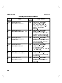
The internal Fade Event feature allows a previously
stored table of notch conditions to be \replayed"
from the front panel. The Fade Event Table is 2000
points long Std., 4000 points long with option 001, and
can be partitioned into 10 sequential or overlapping
segments. The Fade Event table is stored using a remote
controller, but will be preserved in the fader's internal,
battery-backed-up RAM during power o conditions.
1. Press 4 5, then 475.
2. The display will change to \FADE EVENT 0". There are
10 fade events, or segments, that can be replayed. Use
the 485 and 495 arrows or the numeric keypad to select
the desired fade event, then press 4
5.
3. The display will change to \FADING..N" and the
selected fading segment will be run. \N " is the fade
event (0|9) that is currently running.
SHIFT
ENTER
Notes
Pressing any front panel key halts the procedure.
If there is no fade event stored into memory or the fade
event is invalid, the display will read \UNAVAILABLE".
Verify that the event is valid or has been stored.
4. The event will stop when nished and the front panel
will display the values set by the last point in the fade
event just executed.
2-17
Detailed Operating Instructions
Remote Procedure
HP 11757B
To start a fading event in remote mode, send the
command \SWE:ALL LIST" followed by the fade event
number. For example, to start fade event 3:
OUTPUT 714;"SWE:ALL LIST3"
Fade Event Table Storage (Remote Only)
The fade event table is 2000 \points" long (4000 for
option 001). Each \point" contains ve pieces of
information:
Notch frequency
Notch depth
Min/Non-Min phase
Attenuation (at fade)
Sweep time.
Note
The Sweep time information contained in each \point"
is dened as the time to reach that \point" from the
previous \point".
Storing Notch Frequency Portion of Table
To store the notch frequency portion of the table,
use the LIST:FREQ command, followed by the list of
frequencies that will be stored into the table.
For example, to store an array of notch frequency points:
OUTPUT 714;"LIST:FREQ ";Freq_array(*)
To store a set of notch frequency points:
OUTPUT 714;"LIST:FREQ 50E6,55E6, 60E6,65E6,70E6,75E6,80E6,85E6,90E6"
or
OUTPUT 714;"LIST:FREQ 50MHZ,55MHZ,
60MHZ,65MHZ,70MHZ,75MHZ,80MHZ,85MHZ,90MHZ"
2-18
HP 11757B
Detailed Operating Instructions
Storing Notch Depth Portion of Table
To store the notch depth portion of the table, use the
LIST:POW:DEPT command, followed by the list of
notch depths that will be stored into the table.
For example, to store an array of notch depth points:
OUTPUT 714;"LIST:POW:DEPT ";Depth_array(*)
To store a set of notch depth points:
OUTPUT 714;"LIST:POW:DEPT 0,5,10,15,
20,25,30,35,40"
Storing MIN/NON-MIN Phase Portion of Table
To store the MIN/NON-MIN phase portion of the table,
use the LIST:POW:DEPT:PHAS command, followed by
the list of phases that will be stored into the table.
Note
MIN/NON-MIN phase can be abbreviated by \1" for
min-phase or \0" for non-min-phase.
For example, to store an array of MIN/NON-MIN phase
points:
OUTPUT 714;"LIST:POW:DEPT:PHAS ";Phase_array(*)
To store a set of MIN/NON-MIN phase points:
OUTPUT 714;"LIST:POW:DEPT:PHAS 0,
0,1,1,0,0,0,1,0"
or
OUTPUT 714;"LIST:POW:DEPT:PHAS
NONM,NONM,MIN,MIN,NONM,NONM,NONM,MIN,NONM
2-19
Detailed Operating Instructions
HP 11757B
Storing ATTEN Portion of Table
To store the attenuation portion of the table, use the
LIST:POW:ATT command, followed by the list of
attenuations that will be stored into the table.
For example, to store an array of attenuation points:
OUTPUT 714;"LIST:POW:ATT ";Atten_array(*)
To store a set of attenuation points:
OUTPUT 714;"LIST:POW:ATT 0,1,2,3,4,5,6,7,8"
Storing Sweep Time Portion of Table
To store the sweep time portion of the table, use the
LIST:TIME command, followed by the list of sweep
times that will be stored into the table.
For example, to store an array of sweep time points:
OUTPUT 714;"LIST:TIME ";Time_array(*)
To store a set of sweep time points:
OUTPUT 714;"LIST:TIME .1,
.2,.1,.1,.1,.1,3.3,5.5,.1"
Storing the Fade Event Positions
To store where the the 10 Events start and stop, use the
LIST:SSEQn command, where \n " is 0|9 and is the
Event number.
For example, to set Event # 0 to points 1|9 and Event
# 1 to points 5|7:
OUTPUT 714;"LIST:SSEQ0 1,9;SSEQ1 5,7"
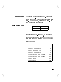
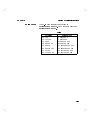
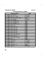
Example
The following is an example of how to generate a fade
event table and store it into the fader. The data for the
table is an example of a specic signature of a radio
2-20
HP 11757B
Detailed Operating Instructions
at 10E-3 and 10E-6, for MIN phase and NON-MIN
phase. The data is divided into 6 fade events that can be
replayed individually. In this example, the user would
monitor the 10E-3 and 10E-6 alarm indicators while
the fading events were running to determine a pass/fail
status for the radio's adaptive equalizer cards.
Event 0: MIN Phase Signature for 10E-3
Point Freq Depth Phase Atten Time
# MHz dB
dB
S
1
2
3
4
5
6
7
8
9
10
11
12
13
55.0
57.5
60.0
62.5
65.0
67.5
70.0
72.5
75.0
77.5
80.0
82.5
85.0
40
35
17
16
18
17
17
17
18
16
17
35
40
1
1
1
1
1
1
1
1
1
1
1
1
1
0
0
0
0
0
0
0
0
0
0
0
0
0
.5
.5
.5
.5
.5
.5
.5
.5
.5
.5
.5
.5
.5
2-21
Detailed Operating Instructions
HP 11757B
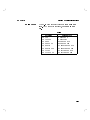
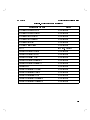
Event 1: NON-MIN Phase Signature for 10E-3
Point Freq Depth Phase Atten Time
# MHz dB
dB
S
14
15
16
17
18
19
20
21
22
23
24
25
26
55.0
57.5
60.0
62.5
65.0
67.5
70.0
72.5
75.0
77.5
80.0
82.5
85.0
40
35
15
14
16
15
15
15
16
14
15
35
40
0
0
0
0
0
0
0
0
0
0
0
0
0
0
0
0
0
0
0
0
0
0
0
0
0
0
.5
.5
.5
.5
.5
.5
.5
.5
.5
.5
.5
.5
.5
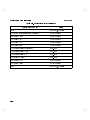
Event 3: MIN Phase Signature for 10E-6
Point Freq Depth Phase Atten Time
# MHz dB
dB
S
27
28
29
30
31
32
33
34
35
36
37
38
39
2-22
55.0
57.5
60.0
62.5
65.0
67.5
70.0
72.5
75.0
77.5
80.0
82.5
85.0
40
30
10
9
11
10
10
10
11
9
10
30
40
1
1
1
1
1
1
1
1
1
1
1
1
1
0
0
0
0
0
0
0
0
0
0
0
0
0
.5
.5
.5
.5
.5
.5
.5
.5
.5
.5
.5
.5
.5
HP 11757B
Detailed Operating Instructions
Event 4: NON-MIN Phase Signature for 10E-6
Point Freq Depth Phase Atten Time
# MHz dB
dB
S
40
41
42
43
44
45
46
47
48
49
50
51
52
55.0
57.5
60.0
62.5
65.0
67.5
70.0
72.5
75.0
77.5
80.0
82.5
85.0
40
30
10
9
11
10
10
10
11
9
10
30
40
0
0
0
0
0
0
0
0
0
0
0
0
0
0
0
0
0
0
0
0
0
0
0
0
0
0
.5
.5
.5
.5
.5
.5
.5
.5
.5
.5
.5
.5
.5
Remote commands to transfer table into fader memory:
OUTPUT 714;"LIST:FREQ
55MHZ,57.5MHZ,60MHZ,
62.5MHZ,65MHZ,67.5MHZ,70MHZ,72.5MHZ,
75MHZ,77.5MHZ,80MHZ,82.5MHZ,85MHZ,
55MHZ,57.5MHZ,60MHZ,62.5MHZ,65MHZ,
67.5MHZ,70MHZ,72.5MHZ,75MHZ,77.5MHZ,
80MHZ,82.5MHZ,85MHZ,55MHZ,57.5MHZ,60MHZ,
62.5MHZ,65MHZ,67.5MHZ,70MHZ,72.5MHZ,
75MHZ,77.5MHZ,80MHZ,82.5MHZ,85MHZ,
55MHZ,57.5MHZ,60MHZ,62.5MHZ,65MHZ,67.5MHZ,
70MHZ,72.5MHZ,75MHZ,77.5MHZ,80MHZ,
82.5MHZ,85MHZ"
OUTPUT 714;"LIST:POW:DEPT
40,35,17,16,18,17,17,17,18,16,17,35,40,
40,35,15,14,16,15,15,15,16,14,15,35,40,
40,30,10,9,11,10,10,10,11,9,10,30,40,
40,30,10,9,11,10,10,10,11,9,10,30,40"
OUTPUT 714;"LIST:POW:DEPT:PHAS
2-23
Detailed Operating Instructions
HP 11757B
1,1,1,1,1,1,1,1,1,1,1,1,1,
0,0,0,0,0,0,0,0,0,0,0,0,0,
1,1,1,1,1,1,1,1,1,1,1,1,1,
0,0,0,0,0,0,0,0,0,0,0,0,0"
OUTPUT 714;"LIST:POW:ATT
0,0,0,0,0,0,0,0,0,0,0,0,0,
0,0,0,0,0,0,0,0,0,0,0,0,0,
0,0,0,0,0,0,0,0,0,0,0,0,0,
0,0,0,0,0,0,0,0,0,0,0,0,0"
OUTPUT 714;"LIST:TIME
.5,.5,.5,.5,.5,.5,.5,.5,.5,.5,.5,.5,.5,
.5,.5,.5,.5,.5,.5,.5,.5,.5,.5,.5,.5,.5,
.5,.5,.5,.5,.5,.5,.5,.5,.5,.5,.5,.5,.5,
.5,.5,.5,.5,.5,.5,.5,.5,.5,.5,.5,.5,.5"
OUTPUT 714;"LIST:SEQ0 1,13"
OUTPUT 714;"LIST:SEQ1 14,26"
OUTPUT 714;"LIST:SEQ2 1,26"
(10E-3 min phase signature)
(10E-3 non-min phase)
(complete 10E-3 signature)
OUTPUT 714;"LIST:SEQ3 27,39"
OUTPUT 714;"LIST:SEQ4 40,52"
OUTPUT 714;"LIST:SEQ5 27,52"
(10E-6 min phase signature)
(10E-6 non-min phase)
(complete 10E-6 signature)
Comments
2-24
PRESET does not aect the Fade Event Tables.
HP 11757B
Detailed Operating Instructions
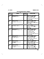
Fast Programming of Notch Parameters
(Remote Only)
For fast programming of the notch parameters
(frequency,phase, depth, and attenuation), use the
DIAG:PROF command followed by notch frequency,
phase, depth, attenuation and slew time to that point.
This is useful for replaying previously stored data that
exceeds the length of the internal fade prole table (4000
points) or for shortening the HP-IB processing time.
Since fast speed is desired for this mode, use the shortest
numeric representations possible. For example, use
\70E6" instead of \70MHZ" or \70000000" for frequency.
Also use \1" for minimum phase and \0" for non-min
phase.
Remote Procedure
Note
The program code for fast programming is DIAG:PROF
followed by frequency, phase, depth, atten and time.
The display will change to \FADING . . . " during fast
programming.
To achieve the fastest speed, keep each HP-IB command
to less than 50 characters.
2-25
Detailed Operating Instructions
Example
HP 11757B
For example, send the following set of information in fast
mode:
Freq Phase Depth Atten Time
MHz
dB
dB
s
62.5
65.0
67.5
70.0
72.5
75.0
77.5
OUTPUT
OUTPUT
OUTPUT
OUTPUT
OUTPUT
OUTPUT
OUTPUT
2-26
1
1
1
1
1
1
1
16
18
17
17
17
18
16
714;"DIAG:PROF
714;"DIAG:PROF
714;"DIAG:PROF
714;"DIAG:PROF
714;"DIAG:PROF
714;"DIAG:PROF
714;"DIAG:PROF
0
0
0
0
0
0
0
.1
.1
.1
.1
.1
.1
.1
62.5E6,1,16,0,.1"
65E6,1,18,0,.1"
67.5E6,1,17,0,.1"
70E6,1,17,0,.1"
72.5E6,1,17,0,.1"
75E6,1,18,0,.1"
77.5E6,1,16,0,.1"
HP 11757B
Detailed Operating Instructions
HP-IB ADDRESS
Description
Local Procedure
HP-IB ADDRESS allows the user to modify the HP-IB
address of the Fader. Values range from 0|30 with 40
as listen only, and 50 as talk only.
To modify the HP-IB ADDRESS:
1. Activate MORE (4 5, then 4
5). The
Fader will display a MORE operation title with a
blinking digit.
2. Use 485 or 495 to modify the blinking digit until the
display reads \5 HP-IB ADRS".
3. Press the 4
5 key. The Fader will display
\ADDRESS 14" with one blinking digit.
4. Modify the blinking digit (see below) until the desired
HP-IB address is displayed.
a. Use 485 and 495 to modify the blinking digit.
b. Use 465 and 475 to move to the adjacent digit.
c. Press the 4
5 key.
SHIFT
PRESET/LOCAL
ENTER
ENTER
Remote Procedure
It is possible to set HP-IB addresses over HP-IB directly.
See HP-IB chapter 5.
2-27
Detailed Operating Instructions
HP 11757B
INIT
Description
Comments
2-28
The INITialize feature is found under the 4 5 key as
item 9. This function clears everything in RAM. It does
not aect items stored in EEPROM or EPROM. The
items cleared include:
Fader settings stored in recall registers.
Current Fader settings.
Calibration data not stored in EEPROM. This will
cause calibration data stored in EEPROM to be
loaded back into RAM.
Fade Events
Test Masks
Radio Setups
Measurement Setups
MORE
After INIT has been executed, the instrument will need
a few seconds to reload data into RAM.
HP 11757B
Detailed Operating Instructions
MEAS
Description
The 4 5 key starts and executes a measurement. The
type of measurement is set by the 4
5 key, and
measurement parameters can be entered after pressing
4
5. The 4
5 key allows you to enter
values specic to the digital radio under test.
When you press 4 5, the display will show ENT TO
MEAS if there is valid measurement data in the Fader
that you will be writing over. Press 4
5 unless you
want to print out the old data rst.
When the measurement is in progress, the display will
do a countdown until the measurement is nished. After
the measurement has been completed, data will be sent
to a printer. The printer can be specied using the
PRINTER key (4 5 4 5).
MEAS
MEAS TYPE
MEAS SETUP
RADIO SETUP
MEAS
ENTER
SHIFT
Notes
MEAS
The measurement functions do not exist on and do not
apply to option 001 Faders.
Dispersive Fade Margin
After the completion of an M-curve measurement
(Static, Dynamic, or Hysteresis), the 11757B computes
and displays the Dispersive Fade Margin. The type of
Dispersive Fade Margin calculation is chosen by DFM
TYPE under the 4
5 key. The two DFM
TYPE choices are Bellcore and CCIR. The CCIR DFM
calculation is only available in serial prexes 3215A and
above.
MEAS SETUP
2-29
Detailed Operating Instructions
HP 11757B
Bellcore Dispersive Fade Margin
The Bellcore Dispersive Fade Margin is explained
in Bellcore Technical Advisory TA-TSY-000752.
Specically:
Fd
Sw
= 17 6 0 10
:
=
Z
e
0
( )
3:8
Bn f
log10
+
e
0
Sw
158 4
:
( )
3:8 df
Bm f
where:
Fd = Bellcore Dispersive Fade Margin
Bn = Non-Min phase M-Curve
Bm = Min phase M-Curve
f = frequency (MHz)
CCIR Dispersive Fade Margin
The Dispersive Fade Margin labelled CCIR(Comite
Consultatif International des Radiocommunications) is
based on ITU Report 784-3 and is calculated as follows:
(
K n M in
(
K n N on
(
K n Overall
2-30
0
)=
M in
T
2 Z
10
s
T
)=
T
2 Z
s
T
0
( )
Bm f
20
10
0
df
( )
20 df
Bn f
0 )
) = 10 10 ( ) + 2 (
where:
Kn = CCIR Dispersive Fade Margin
Bn = Non-Min phase M-Curve
Bm = Min phase M-Curve
Ts = Radio symbol time (ns)
T = Fader delay time (6.3 ns)
f = frequency (GHz)
log
K n M in
K n N on
M in
HP 11757B
Detailed Operating Instructions
Note
If an HP 859X Spectrum Analyzer with the M-Curve
Measurements DLP is used to display the M-Curve
graphically, the result shown at the top of the display is
always the Bellcore result. The CCIR result is displayed
on the HP11757B Front Panel only (when CCIR is
selected).
Dispersive Fade Margin with only one Phase.
If only one phase was selected for measurement, the
11757B will assume the phase that was not measured
will have the same M-curve as the phase that was
measured.
Dispersive Fade Margin with Hysteresis Measurements.
The Dispersive Fade Margin for a Hysteresis
Measurement is the average of the Outage and Return
Dispersive Fade Margins.
2-31
Detailed Operating Instructions
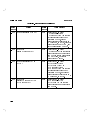
HP 11757B
MEAS SETUP
Description
The 4
5 key accesses setup options for
measurements. The numbered items are:
MEAS SETUP
0 DATA PTS
This option is used for all measurements except Recovery
Time. It species the number of frequency data points
(1 to 100) that will be calculated and measured. It
species the number of sweep rate points when a
Dynamic-S measurement is made. The points are evenly
distributed between the start and stop frequencies. If
you specify 20 points for min and non-min phase, a
Static M-Curve, Dynamic M-Curve or Dynamic S-Curve
measurement will create 20 points for min and 20 points
for non-min, for a total of 40 points. If you specify 20
points for a hysteresis measurement, 80 points would be
created.
1 STRT FRQ and 2 STOP FRQ
These options are used to set the start and stop
frequencies for Static and Dynamic M-Curve, and
Hysteresis measurements. For Dynamic S-Curve, the
start and stop frequencies dene the start and stop
points for the sweep. The stop value does not have to be
larger than the start value. Values are band dependent.
You cannot have a start frequency in one band, and a
stop frequency in another.
3 START RATE and 4 STOP RATE
These options are used for DYNM S (the S-Curve)
measurements only. The upper limit is dependent on
the frequency span used. The fastest the fader will slew
from one point to another is 5 ms (10 ms for a complete
cycle). The upper limit = jstart 0 stopj 4 .01
2-32
HP 11757B
Detailed Operating Instructions
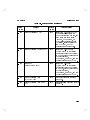
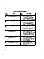
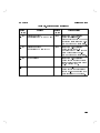
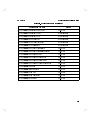
5 ERROR BITS
Error Bits controls the number of errors that are counted
before a nal bit error rate calculation is made. The
numbers that can be entered range from 2 to 15 and
represent powers of 2 (entering a 10 will cause 1024
errors to be counted). The 11757B keeps track of the
amount of time, t1, it takes for the number of error
pulses specied by ERROR BITS to occur. It uses this
time to calculate an error rate.
Error rate = ERRORBITS
t1
This is then used along with SCALE FACTOR and
the radio's BIT RATE to compute the bit error rate as
follows.
Bit error rate = Error rate scalefactor
Bitrate
It is important to understand the impact of dierent
ERROR BITS settings. Large ERROR BITS settings
will provide more accurate and repeatable M-Curves
than small ERROR BITS settings. This is because
larger settings require the 11757B to count many errors
(rather than few) before a BER is calculated.
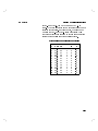
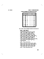
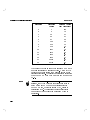
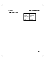
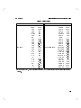
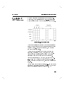
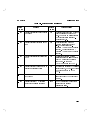
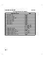
A study in statistics arrives at the table below which
shows the relationship between ERROR BITS and the
maximum percent error possible in the BER calculation.
Use this as a guide when selecting an ERROR BITS
setting.
2-33
Detailed Operating Instructions
HP 11757B
Error Bits
2
3
4
5
6
7
8
9
10
11
12
13
14
15
True Error
Counts
4
8
16
32
64
128
256
512
1024
2048
4096
8192
16384
32768
Maximum % Error
(90% Condence)
120
78
54
34
22
16
11
7.0
4.6
3.2
2.1
1.4
.96
.64
The tradeo that comes about with larger ERROR BITS
numbers is increased measurement time. As the 11757B
waits to count more errors, the measurement time will
increase accordingly. This eect is particularly noticeable
when the ERROR CRITERIA is a very low BER such as
1E06.
Note
2-34
When the DYNAMIC-M or DYNAMIC-S test is
selected, the 11757B will wait for at least one cycle of
notch movement OR the number of errors specied
in ERROR BITS, whichever occurs LAST, before it
calculates a BER. This insures the radio is subjected
to a uniform dynamic test even under slow dynamic
conditions.
HP 11757B
Detailed Operating Instructions
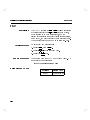
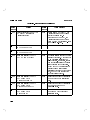
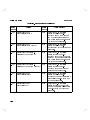
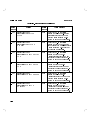
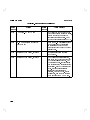
6 PHASE
This selects which phase will be measured (MIN or
NON-MIN or BOTH). If type BOTH is selected, two
separate measurements will be made. BOTH is used
only for Static-M, Dynamic-M, and Dynamic-S. If type
MIN or NON-MIN are selected, the dispersive fade
margin is calculated as if both phases are identical.
7 CRITERIA
This selects the decision criteria for drawing an MCurve. If ALARM is selected, the curve will be drawn
where the radio alarm signal goes high or low. If BER
is selected, the curve will be drawn where the specied
BER threshold is met. Criteria choices are: 1E-3, 3E-4,
1E-4, 3E-5, 1E-5, 1E-6, and ALARM.
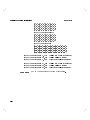
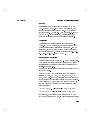
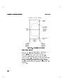
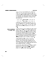
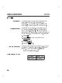
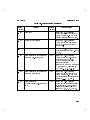
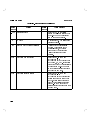
8 SPEED and 9 DEVIATION
These are used for the Dynamic M-Curve measurements.
They specify the speed (rate) and frequency deviation
to sinusoidally modulate the frequency position of the
carrier. See gure 2-1.
The SPEED equals the peak frequency per second of the
notch movement.
The DEVIATION can be selected from the following
values: 61 MHz, 62 MHz, 64 MHz, 66 MHz, 610
MHz, 620 MHz. However, deviation must not cause the
Fader to exceed the frequency limits of the band it is in.
An additional 4 MHz of guardband should be added so
that the allowable deviations for given start and stop
frequencies are:
START FREQ 0 (jDeviationj+4 MHz) 40 MHz
STOP FREQ + (jDeviationj+4 MHz) 100 MHz
For instance, if your start sweep frequency is 45 MHz
and your deviation is 2 MHz, an error will result because
2-35
Detailed Operating Instructions
HP 11757B
the frequency (45 MHz 0 (2 MHz + 4 MHz ) = 39
MHz) is outside the range of frequencies (40 MHz to 100
MHz std.).
Figure 2-1. Speed and Deviation
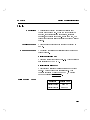
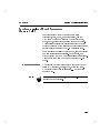
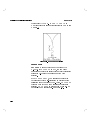
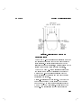
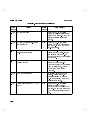
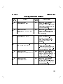
10 EDGE ZOOM
EDGE ZOOM is used to focus on
the edges of the
M-Curve. If EDGE ZOOM is OFF, the number of
measurement points you select will be evenly distributed
across the X-axis for the measurement you have
specied.
If EDGE ZOOM is ON, the measurement points you
have specied will be re-distributed to provide better
resolution near the edges of the M-Curve. EDGE ZOOM
will only work if 15 or more measurement points are
specied. EDGE ZOOM is not used for Dynamic-S or
Recovery Time measurements. See gure 2-2.
2-36
HP 11757B
Detailed Operating Instructions
Figure 2-2. Edge Zoom
11 MK SEARCH
Digital radios use In-phase/Quadrature (I/Q)
modulation techniques; there are I and Q baseband
channels in both the receiver and the transmitter. When
a radio receiver locks onto the transmitted signal, it can
lock up in one of two ways:
Tx I to Rx I and Tx Q to Rx Q
Tx I to Rx Q and Tx Q to Rx I
where Tx and Rx stand or transmitter and receiver.
Because lters and other components in baseband
channels are not completely identical, the performance
of the radio during multipath fading could be dierent
depending on which of the two states the radio locks up
in.
If the MK SEARCH is ON, the M-Curve measurement
algorithm is modied to search for the worst case
(smallest notch depth) lock state. This is done by
repeatedly unlocking the radio during the measurement
and allowing the radio to lock up in a dierent state.
The measurement proceeds until 2 states are found,
or 20 lock/unlocks have been performed. The worst
case lock state is what is displayed on the output data.
Because this feature causes extra measurements to be
made, it will increase the overall measurement time.
2-37
Detailed Operating Instructions
HP 11757B
If MK SEARCH is OFF, the M-Curve algorithm will
proceed as described under the MEASURE TYPE key.
MK SEARCH is not used for Dynamic-S or Recovery
Time measurements.
12 DFM TYPE
Allows selection of the CCIR or Bellcore DFM type.
See MEAS in this section of the manual for more
information. The CCIR DFM calculation is only
available in serial prexes 3215A and above.
Note
2-38
The measurement setup parameters and functions do not
apply to option 001 instruments.
HP 11757B
Detailed Operating Instructions
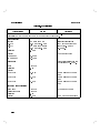
MEAS TYPE
M-Curve
Measurements
This key selects the type of measurement to be made.
The 11757B makes 6 dierent measurements that can be
grouped into 4 categories.:
1. M-Curves
a. Static M-Curve
b. Dynamic M-Curve
c. Hysteresis M-Curve
2. S-Curves
a. Dynamic S-Curve
3. Recovery Time
4. Bit Error Rate
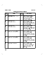
An M-Curve is made by creating a notch and moving it
from frequency to frequency in and around the radio
spectrum. At each frequency, the notch is moved in a
prescribed way until a user specied criteria is met.
This criteria is usually a specic Bit Error Rate, such as
1E03. However, with the HP 11757B this criteria can
also be the transition of a signal on the Alarm Input. By
connecting an Alarm Line from the radio (or a BERT)
this feature will allow you to set the criteria at the
point where the radio goes out of lock. The result of
this measurement is a number of frequency/notch depth
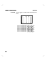
points which cause the radio to meet the chosen criteria.
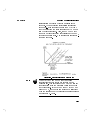
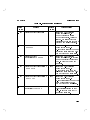
When plotted as shown in gure 2-3, these points form
an M-Curve. The HP 11757B provides 3 basic types of
M-Curve Measurements, STATIC, HYSTERESIS, and
DYNAMIC.
2-39
Detailed Operating Instructions
HP 11757B
Figure 2-3. Typical M-Curve Output
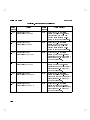
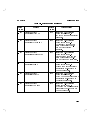
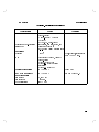
Static (Static M-Curve)
The STATIC M-Curve is similar to what is shown
in gure 2-3. The notch will start at the START
FREQuency and at a NOTCH DEPTH of 0 db.
The notch will increase in depth until the ERROR
CRITERIA is met. This notch depth is then stored and
the notch is set to the next frequency point at 0 db
depth. This process, depicted in gure 2-4, continues
until the specied number of frequency points have been
measured.
2-40
HP 11757B
Detailed Operating Instructions
Figure 2-4. Static M-Curve Measurement
Hysteresis M-Curve
The STATIC M-Curve measurement described a method
of measurement were the depth of the notch is always
being increased. Because certain radios may have a
signicant amount of hysteresis, a dierent result may be
arrived at if the notch is always being decreased.
The HYSTERESIS M-Curve measurement allows you
to measure the amount of hysteresis in your radio by
making two M-Curve measurements; one with the
notch increasing (the outage) and one with the notch
decreasing (the return).
Figure 2-5 describes how this is done. The 11757B is
rst put into minimum phase fading with the notch
depth at 0 db. The notch is then increased until the
ERROR CRITERIA is achieved. This is point #1 in
gure 2-5 and corresponds to the Outage point for
2-41
Detailed Operating Instructions
HP 11757B
minimum phase. The notch is then increased further
until a depth of 40 db is achieved. At this point the
fader switches to non-minimum phase and the notch
depth is decreased until the ERROR CRITERIA is again
achieved. This is point #2 in gure 2-5 and corresponds
to the Return point for Non-minimum phase.
This process is then repeated, with the phases reversed,
for points #3 (Outage point for Non-minimum phase)
and #4 (Return point for minimum phase). Both points
(outage and return) are displayed for each frequency
point on the printed output. Because of the way this
measurement is made, HYSTERESIS M-Curve can only
be made for BOTH phases.
Figure 2-5. Hysteresis-M Measurement
Dynamic M-Curve
The Dynamic M-Curve is identical to the Static
M-Curve with the exception that the notch frequency
2-42
HP 11757B
Detailed Operating Instructions
is sinusoidally modulated while the measurement is
underway. This modulation is pictorially represented
in gure 2-6. It is important to note the DEVIATION
that you enter from the front panel is plus AND minus
from the center frequency. Also, the SPEED at which
the notch moves in frequency is expressed as the peak
rate over one entire cycle. The average rate is actually 1
times the peak rate.
Figure 2-6. Dynamic M-Curve Measurement
Note
The DEVIATION and SPEED that you choose
can signicantly eect the time it takes to make a
measurement. This is because the HP 11757B will wait
for at least one cycle of modulation before it computes
the bit error rate. If you have a wide DEVIATION and
a slow SPEED, the time for one cycle can be signicant
when you consider many bit error rate measurements are
made for each M-Curve.
2-43
Detailed Operating Instructions
HP 11757B
The DEVIATION can be selected from the following
values: 61 MHz, 62 MHz, 64 MHz, 66 MHz, 610
MHz, 620 MHz. However, deviation must not cause the
Fader to exceed the frequency limits of the band it is in.
An additional 4 MHz of guardband should be added so
that the allowable deviations for given start and stop
frequencies are:
START FREQ 0 (jDeviationj+4 MHz) 40 MHz
STOP FREQ + (jDeviationj+4 MHz) 100 MHz
For instance, if your start sweep frequency is 45 MHz
and your deviation is 2 MHz, an error will result as the
frequency (45 MHz 0 (2 MHz + 4 MHz) = 39 MHz) is
outside the range of frequencies (40 MHz to 100 MHz
std.).
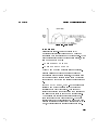
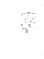
Dynamic S-Curve
Measurements
2-44
While a Dynamic M-Curve measurement checks a radios
performance with a notch that varies in frequency over
a narrow region, a Dynamic S-Curve measurement is a
measure of how the radio responds to a notch sweeping
back and forth across the entire band of the radio. The
measurement is made by setting the notch to sweep
across the specied band at a particular rate (see gure
2-7). While sweeping is occurring, the notch depth is
increased until the ERROR CRITERIA is reached.
After achieving the desired ERROR CRITERIA,
the notch depth is brought back to 0 db, and the
speed at which the notch sweeps across the band is
increased. The notch is again lowered until the ERROR
CRITERIA is reached. This process is repeated until the
highest desired sweep RATE is tested.
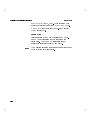
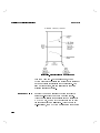
The data from this measurement is presented in a graph
similar to the one shown in gure 2-8. This graph is
dierent from M-Curve graphs in that the x-axis is
sweep RATE instead of notch frequency.
HP 11757B
Detailed Operating Instructions
Figure 2-7. Dynamic S-Curve Measurement
2-45
Detailed Operating Instructions
HP 11757B
Figure 2-8. Dynamic S-Curve Measurement
Like the Dynamic M-Curve measurement, the HP
11757B will wait for at least one cycle of notch frequency
movement before it calculates the bit error rate. For
slow moving notches, this can signicantly eect the
overall measurement speed.
Recovery Time
2-46
Recovery Time is a measure of the time it takes the
radio to re-lock after the IF path has been broken.
After the user selects this measurement and presses the
MEASURE key, the HP 11757B will break the IF path
for approximately 20 milliseconds. After the path is
re-established, the HP 11757B measures the time for the
HP 11757B
Detailed Operating Instructions
ERROR CRITERIA to be reached. The resulting time is
displayed on the front panel.
The HP 11757B does not reset the notch during a
RECOVERY time measurement. For this reason, you
should make sure the notch is set to the position you
want before you start the measurement. For example, if
you want to measure the radios ability to re-aquire lock
while a 30 dB notch is in eect, set the notch depth to
30 dB and then start the measurement.
You can set the Fader to measure recovery time with a
notch in the IF path. Simply set a notch at a frequency
of interest so that when the IF path is broken and
re-established, the notch is there.
Bit Error Rate
Measurement
The bit error rate measurement type measures the BER
by simply counting the number of events that occur on
the ERROR PULSE input for approximately 1 second.
It then uses the bit rate and scale factor to calculate the
BER. The resulting BER is displayed on the front panel.
The BER measurement runs continuously, displaying a
new BER every 0.5 seconds, until the 4
5 key
is pressed.
You can set the Fader to measure the bit error rate
with a notch in the IF path. Simply set a notch at a
frequency of interest so that when the bit error rate is
measured, the notch is there.
Bit error rate measurement type is only available in
serial prexes 3215A and above.
PRESET/LOCAL
Test Parameters
The following table shows which parameters are needed
for each of the Fader tests. An x indicates that the
parameter should be entered and will be printed.
2-47
Detailed Operating Instructions
Meas Setup
Data Points
Start Freq
Stop Freq
Static M Static M Dynamic
Hyster
Hyster
S
Threshold Alarm Threshold
x
x
x
x
x
x
x
x
x
x
x
x
x
x
x
x
x
Start Rate
Stop Rate
Error Bits
Phase
Criteria
HP 11757B
x
x
x
x
x
x
x
x
Dynamic Dynamic Dynamic Recov Recov BER
S
M
M
Threshold Alarm
Alarm Threshold Alarm
x
x
x
x
x
x
x
Speed
Deviation
Edge Zoom
MK Search
DFM Type
Radio Setup
Bit Rate
Error Term
Error Thresh
Alarm Pol
Scale Factor
AGC (on/o)
AGC Freq
AGC BW
Wait time
Max slew
Symbol time
Other Setup
Delay
Test Mask
2-48
x
x
x
x
x
x
x
x
x
x
x
x
x
x
x
x
x
x
x
x
x
x
x
x
x
x
x
x
x
x
x
x
x
x
x
x
x
x
x
x
x
x
x
x
x
x
x
x
x
x
x
x
x
x
x
x
x
x
x
x
x
x
x
x
x
x
x
x
x
x
x
x
x
x
x
x
x
x
x
x
x
x
x
x
x
x
x
x
x
x
x
x
x
x
x
x
x
x
x
x
x
x
x
x
x
x
x
HP 11757B
Detailed Operating Instructions
The AGC Frequency and Bandwidth will be printed only
if AGC is on.
Phase does not need to be selected for Hysteresis
measurements. It is always BOTH.
Symbol time is only used when the DFM type is CCIR.
Note
Notes
The measurement types do not apply to option 001
instruments.
2-49
Detailed Operating Instructions
HP 11757B
MORE
Description
The MORE key is used to access a group of operations.
These operations are listed below.
0 SLEW TIME
1 SINGLE SWEEP
2 AGC ON/OFF
3 AGC FREQ
4 AGC BW
5 HP-IB ADRS
6 SYNC SOUR
7 SELF TEST
8 SERVICE
9 INIT
10 SET TIME
11 SET DATE
12 MASK CTRL
There are two levels of operation when in MORE mode:
Level 1, which allows the user to view and access the
operations listed above.
Level 2, which allows the user to modify or review the
settings of the parameters of the operations.
Level 1 is accessed by pressing the MORE (4 5, then
4
5) key. Level 2 is accessed by pressing the
4
5 key while a level 1 operation is selected. At the
end of a level 2 operation pressing the 4
5 key will
return you to the normal display.
SHIFT
PRESET/LOCAL
ENTER
ENTER
2-50
HP 11757B
Detailed Operating Instructions
Local Procedure
Note
The following is a general procedure to access the
MORE mode and select a level 2 operation. Detailed
instructions to access specic level 2 operations are
covered in other Detailed Operating Instructions.
To access the MORE mode:
1. Activate the MORE (4 5, then 4
5)
function. The Fader will display an operation title
with a blinking digit.
2. Use 485 or 495 to modify the blinking digit until the
desired operation title is displayed.
3. Press the 4
5 key to access the displayed
operation in level two.
SHIFT
PRESET/LOCAL
ENTER
Remote Procedure
Comments
It is not possible or necessary to access the MORE
mode. All of the operations in MORE mode have their
own individual HP-IB codes.
The EXIT (4 5, then 4
out of MORE mode.
SHIFT
) key takes the Fader
5
ENTER
2-51
Detailed Operating Instructions
HP 11757B
NOTCH DEPTH
Description
Local Procedure
This key allows you to set the notch depth in dB. The
range of values is 0 to 40 dB (you may actually set up to
99.9) with a resolution of 0.1 dB. Notch depth may be
swept, but at a maximum slew rate of 400 dB per second
(40 dB/0.1 sec).
1. Press the NOTCH DEPTH key.
2. Use the 485 and 495 keys to modify the blinking digit.
3. Use the 465 and 475 keys to move to other digits for
modication.
4. Press the 4
5 key when you have the value you
want.
ENTER
or
1. Press the 4
5 key.
2. Use the data entry keys to enter the value in dB.
3. Press the 4
5 key.
To sweep the notch depth:
1. Press the 4
5 key.
2. Press the 4
5 key.
3. Use the arrow keys or the data entry keys to enter the
desired starting notch depth.
4. Press the 4
5 key.
5. Press the 4
5 key.
6. Press the 4
5 key.
7. Use the arrow keys or the data entry keys to enter the
desired notch depth to stop the sweep at.
8. Press the 4
5 key.
NOTCH DEPTH
ENTER
SET START
NOTCH DEPTH
ENTER
SET STOP
NOTCH DEPTH
ENTER
2-52
HP 11757B
Detailed Operating Instructions
9. Press 4
5 4NOTCH
SHIFT
Remote Procedure
5
DEPTH
The program code for NOTCH DEPTH is POW:DEPT.
Example
Set the NOTCH DEPTH to 25 dB.
OUTPUT 714;"POW:DEPT 25 DB"
Set the start and stop parameters of a NOTCH DEPTH
sweep to 10 and 25 dB.
OUTPUT 714;"POW:DEPT:STAR 10DB"
OUTPUT 714;"POW:DEPT:STOP 25DB"
To start a notch depth sweep:
OUTPUT 714;"POW:DEPT:MODE SWE"
HP-IB Program Codes
Keystroke
NOTCH DEPTH
SET START
SET STOP
SWP DEPTH
Comments
Program Code
POW:DEPT
POW:DEPT:STAR
POW:DEPT:STOP
POW:DEPT:MODE SWE
The preset value for notch depth is 0 dB. The preset
value for start sweep is 20 dB, stop sweep is 20 dB, and
the preset mode for sweep depth is OFF.
2-53
Detailed Operating Instructions
HP 11757B
NOTCH FREQ
Description
Local Procedure
The 4
5 key allows entry of the center
frequency of the notch. The values range from 30|100
MHz for a 70 MHz Fader, and from 100|180 MHz for a
140 MHz Fader (Option 140).
NOTCH FREQ
1. Press the 4
5 key. The Fader will display
the last frequency entered, with one digit blinking. (If
the Fader has been PRESET, the display will read
\70.0 0.0 0.0".)
2. Modify the blinking digit (see below) until the desired
frequency is displayed.
a. Use 485 or 495 to modify the blinking digit.
b. Use 465 or 475 to move to other digits.
c. Press the 4
5 key.
NOTCH FREQ
ENTER
or
3. Press the 4
5 key.
4. Use the data entry keys to enter the desired value of
frequency.
5. Press the 4
5 key.
To sweep Notch Frequency:
1. Press 4
5
2. Press 4
5
3. Use the arrow keys to modify the value shown in
the display to the value you wish to start the notch
frequency sweep from.
4. Press 4
5
5. Press 4
5
NOTCH FREQ
ENTER
SET START
NOTCH FREQ
ENTER
SET STOP
2-54
HP 11757B
Detailed Operating Instructions
6. Press 4
5
7. Use the arrow keys to modify the value shown in the
display to the value you wish to sweep to.
8. Press 4
5
9. Press 4 5
10. Press 4
5
NOTCH FREQ
ENTER
SHIFT
NOTCH FREQ
Note
Remote Procedure
If you do not have a start or stop notch depth 0 set,
you may not see anything sweep.
>
To enter a frequency value, send the command FREQ
followed by the numerical frequency value, the frequency
units code (MHZ, KHZ, or HZ).
Example
To enter a NOTCH frequency of 45 MHz:
OUTPUT 714;"FREQ 45.0MHZ"
HP-IB Program Codes
Parameter
NOTCH FREQ
SET START
SET STOP
SWP FREQ
Comments
Program Code
FREQ
FREQ:STAR
FREQ:STOP
FREQ:MODE
SWE
PRESET sets the NOTCH FREQ value to 70.0 MHz,
the sweep start value to 45 MHz, the sweep stop value to
95 MHz, and the notch frequency sweep mode to OFF.
2-55
Detailed Operating Instructions
HP 11757B
PHASE
Description
The 4
5 key toggles the dominant signal between
the delayed path and the non-delayed path. The
preset condition is minimum phase (non-delayed path
dominant). The annunciator will display the current
setting of the instrument. A marker will appear above
MIN or NON-MIN.
MIN/NON-MIN PHASE can be set for start and stop on
a sweep. After pressing 4
5 or 4
5, check
the state of the annunciator, MIN or NON-MIN, and set
the state as desired using the 4
5 key before pressing
4
5. When you have MIN set for start sweep and
NON-MIN set for stop sweep, or NON-MIN set for start
sweep and MIN set for stop sweep, the Fader changes
phase in the middle of the sweep range.
PHASE
SET START
SET STOP
PHASE
ENTER
Local Procedure
1. Check the annunciator panel to see what state, MIN
or NON-MIN, the simulator is presently set to.
2. Press the 4
5 key. The annunciator should show
a change from one state to the other.
3. Press the 4
5 key again. The annunciator should
toggle back to the previous state.
As an example of how to set non-minimum phase for
starting notch depth of a sweep, and minimum phase
for the end of the sweep:
4. Press the 4
5 key.
5. Press the 4
5 key.
6. Press 4 5 4 5 4 5 4 5
7. Check the MIN and NON-MIN annunciators. If the
MIN state is set, press 4
5 to toggle the indicator
to NON-MIN.
PHASE
PHASE
SET START
NOTCH DEPTH
1
0
.
0
PHASE
2-56
HP 11757B
Detailed Operating Instructions
8.
9.
10.
11.
12.
Press the 4
5 key.
Press the 4
5 key.
Press the 4
5 key.
Press 4 5 4 5 4 5 4 5
Check the MIN and NON-MIN annunciators. If the
NON-MIN state is set, press 4
5 to toggle the
indicator to MIN.
13. Press 4
5
14. Press 4 5, then 4
5
ENTER
SET STOP
NOTCH DEPTH
4
0
.
0
PHASE
ENTER
SHIFT
Remote Procedure
NOTCH DEPTH
The program codes for MIN and NON-MIN are
POW:DEPT:PHAS MIN and POW:DEPT:PHAS
NONM. To sweep phase just sweep notch depth. The
following line shows how to set a starting phase of NONMIN:
OUTPUT 714;"POW:DEPT:STAR:PHAS NONM"
The following line sets the stop phase to MIN:
OUTPUT 714;"POW:DEPT:STOP:PHAS MIN"
The following line sets notch phase to minimum:
POW:DEPT:PHAS MIN
2-57
Detailed Operating Instructions
HP 11757B
HP-IB Program Codes
Keystroke
MIN PHASE
NON-MIN
PHASE
SET START
SET STOP
Comments
2-58
Program Code
POW:DEPT:PHAS MIN
POW:DEPT:PHAS NONM
POW:DEPT:STAR:PHAS MIN
POW:DEPT:STAR:PHAS NONM
POW:DEPT:STOP:PHAS MIN
POW:DEPT:STOP:PHAS NONM
PRESET sets phase to MIN, start phase to MIN, and
stop phase to MIN.
HP 11757B
Detailed Operating Instructions
PRESET/LOCAL
Description
The 4
5 key sets the Fader to a known state.
Preset conditions are shown in the following table. When
the Fader is in remote mode, pressing the 4
5
key places the instrument in local mode. Local mode
gives control of the Fader to the front panel keys.
PRESET/LOCAL
PRESET/LOCAL
Preset Values
Parameter
AGC Bandwidth
AGC Frequency
AGC ON/OFF
Alarm Polarity
ATTENUATION
DATA POINTS
DELAY
DEVIATION
DFM TYPE
DISPLAY
ERROR BITS
ERROR TERM
FADE EVENTS
MAX SLEW(RADIO
SETUP)
MEAS SETUP PHASE
MK SEARCH
NOTCH FREQ
NOTCH DEPTH
Condition
30 MHz
70 MHz (140 in Opt. 140)
OFF
Positive
0.0 dB
10
6.3 ns
61 MHz
Bellcore
ON
1024 ( 2^10 )
ECL/75
OFF
200 dB/sec
MIN
OFF
70 MHz (140 MHz in Option
140)
0 dB
2-59
Detailed Operating Instructions
HP 11757B
Preset Values (continued)
Parameter
NOTCH PHASE
PRINT SELECT
RADIO BIT RATE
RADIO DEMO
SCALE FACTOR
SET START
Attenuation
Notch Depth
Notch Freq
Notch Phase
SET STOP
Attenuation
Notch Depth
Notch Freq
Notch Phase
SIGNATURE TYPE
SINGLE SWEEP
SLEW TIME
SLOPES
SPEED
START RATE
STOP CRITERIA
STOP RATE
SYMBOL TIME
SWP ALL
SWP ATTEN
SWP DEPTH
SWP FREQ
SWP TIME
SYNC SOUR
TEST MASK
WAIT TIME
ZOOM MODE
11757A TIMER
2-60
MIN
NONE
44.7 MHz
OFF
1
Condition
0.0 dB
20.0 dB
45.0 MHz (115 MHz in Option
140)
MIN
0.0 dB
20.0 dB
95.0 MHz (165 MHz in Option
140)
MIN
STATIC
OFF
100 ms
OFF
300 MHz/sec
10 MHz/sec
1E04
100 MHz/sec
50 ns
OFF
OFF
OFF
OFF
5 seconds
Immediate
OFF
500 mS
OFF
RESET
HP 11757B
Detailed Operating Instructions
Local Procedure
To set the Fader to the conditions shown in the
preceding table:
1. Press the 4
5 key. The Fader will display
\ENT TO PRSET".
2. Press the 4
5 key.
PRESET/LOCAL
ENTER
Remote Procedure
The program code for PRESET is *RST. To set the
Fader to the preset conditions, send the *RST command.
HP-IB Program Codes
Comments
Parameter
Program Code
PRESET
*RST
The PRESET routine can be avoided by pressing EXIT
(4 5, then 4
5) before pressing the 4
5 key.
PRESET has no eect on front panel storage registers 1
through 10 or the internal fading event memory. When
PRESET is activated, the Fader is set to the conditions
shown in the previous table.
PRESET does not aect test mask data.
PRESET erases measurement data.
SHIFT
ENTER
ENTER
2-61
Detailed Operating Instructions
HP 11757B
PRINTER
Description
The PRINTER key (4 5 4 5) will access printer
options. It will allow you to select between an external
HP-IB ThinkJet TM or compatible printer, the internal
thermal printer, or no printer (EXTERNal, INTERNal
or NONE). It also allows you to set the print mode
(NONE, PRVIEW, or DATA).
SHIFT
MEAS
External Printer Setup
The Fader must be in talk only mode. This is done by
setting the Fader's HP-IB address to 50. See the HP-IB
ADRS setting under the MORE key.
The external ThinkJet printer must be placed in listen
always mode. The procedure for setting it in this mode
is as follows:
1. Turn the power to the ThinkJetTM printer o.
2. Find the HP-IB switches on the back panel of the
printer.
3. Set the listen always switch to the up position. This
switch is second from the left and is labeled.
4. Connect an HP-IB cable between the printer and the
Fader.
5. Turn the power back on. The printer only scans
the switch settings at power up. If you change the
switches while the printer is powered up, the printer
will not recognize the settings until the printer has
powered o and on again.
6. Check to see that the printer is ON LINE. The light
below the square blue button should be on. If not,
press the blue button on the top of the printer.
2-62
HP 11757B
Detailed Operating Instructions
Note
If you are using an external printer, there must not be
any other controllers on the bus during printing. If
you have a spectrum analyzer or some other controller
device, disconnect the HP-IB cable to that device during
printing.
Setting the Destination.
The options for destination are NONE, INTERNal,
and EXTERNal. NONE species that no printing will
take place. INTERN species that the internal printer
will be used when a measurement is made or when a
specic print mode is selected. EXTERN species that
an external printer will be used when a measurement is
made or when a specic print mode is selected.
Setting the Mode
The options for print mode are PRVIEW and DATA.
PRVIEW species that the current measurement data
and radio setup parameters will be printed. DATA
will cause the M-Curve data and graph from the most
recent measurement to be re-printed to the destination
printer. The graph and data are automatically sent to
the destination printer after each measurement.
2-63
Detailed Operating Instructions
Example
HP 11757B
To set up the Fader to print the measurement setup to
an external printer:
1. Press: 4 5 4 5
2. Use the 485 key until the display reads \1 DEST",
press 4
5
3. Use the arrow keys until the display reads \DST
EXTERN", then press 4
5.
4. Press: 4 5 4 5
5. Use the 485 key until the display reads \2 PRINT",
press 4
5
6. Use the arrow keys until the display reads \PRINT
PRVIEW", then press 4
5.
SHIFT
MEAS
ENTER
ENTER
SHIFT
MEAS
ENTER
ENTER
2-64
HP 11757B
Detailed Operating Instructions
RADIO SETUP
Description
This key allows you to set the following:
0 BIT RATE This allows you to enter the bit rate of
the data line you are monitoring. The preset rate is
44.70 MHz. It may be set from 0.01 to 200 MHz.
1 ERROR TERM This allows you to set the ERROR
PULSE INPUT termination type. The types are
ECL/75
, TTL/75
, TTL/10k
, variable threshold
75
with -2 V termination, variable threshold 75
with 0 V termination, and variable threshold 10k
with 0V termination. The preset is ECL/75
.
1.1 ERROR THR This allows you to set the ERROR
PULSE input threshold. The preset is -1.3 V because
ERROR TERM is preset to ECL/75
. Error pulse
input variable threshold is only available in serial
prexes 3235A and above.
2 ALARM POL This allows you to set the edge trigger
for the ALARM INPUT. The preset is positive edge.
3 SCALE FACT This allows you to scale the errors
that are received by the Fader on the error input, and
is used in conjunction with BIT RATE to compute
the BER (Bit Error Rate). Specically, the Fader
computes BER as:
BER = errors per second scalefactor
bitrate
where the errors per second are as counted on the
ERROR PULSE INPUT.
The default scale factor is 1.0
4 AGC ON/OFF Allows you to turn the Automatic
Gain Control on or o. The preset state is o.
This function can also be accessed from the 4 5
functions key.
MORE
2-65
Detailed Operating Instructions
HP 11757B
5 AGC FREQ Allows you to set the AGC frequency.
The range of acceptable values is 40 to 190 (MHz).
This function can also be accessed from the 4 5
functions key.
6 AGC BW Allows you to set the AGC bandwidth.
The range of acceptable values is 1 to 40 (MHz). The
preset value is 30.0 MHz. This function can also be
accessed from the 4 5 functions key.
7 WAIT TIME Allows you to set a waiting period
after every notch movement during an M-Curve
measurement. This wait allows your radio some
settling time before a Bit Error Rate measurement is
made by the Fader. The range of allowable values is
10 milliseconds to 10 seconds. The preset value is 500
milliseconds.
8 MAX SLEW Allows you to set the notch depth
maximum slew rate for an M-Curve measurement.
This maximum slew rate is used only during M-Curve
measurements and should not be confused with the
\SLEW TIME" parameter used under normal Fader
operation. The range of allowable values for MAX
SLEW is 10 to 500 dB/second. The preset value is 200
dB/second.
MORE
MORE
Note
The preset values for WAIT TIME and MAX SLEW
have been chosen to work with most radios. Modifying
these two paramenters will have a signicant eect on
total measurement time (increasing WAIT TIME and/or
decreasing MAX SLEW will slow the measurement
down). If you are getting inconsistent readings (even
if MK SEARCH is on), it may be the measurement is
proceeding too fast. Use these two features to modify
the speed of the measurement until you get consistent
results.
9 SYMBL TIME This allows you to enter the radio's
symbol time for use when calculating the CCIR DFM
value. The preset is 50 ns. It may be set from 10 to
2-66
HP 11757B
Detailed Operating Instructions
1000 ns. CCIR DFM calculation is only available in
serial prexes 3215A and above.
10 RADIO DEMO Allows you to demonstrate the
signature capabilities of the Fader without a digital
radio present. This feature simulates the presence
of a digital radio and BERT so that that you can
demonstrate a signature measurement and print
results. This feature is either on or o. When it is on,
all parameters and the measurement type are used in
the simulation when 4 5 is pressed. The Fader even
simulates the time it takes for a measurement. MK
SEARCH and other features are simulated. The preset
for RADIO DEMO is o. This feature should be kept
MEAS
o when you are not demonstrating the instrument.
The Fader will ignore a real radio during an actual
measurement if RADIO DEMO is ON.
Notes
The Radio Setup functions and parameters do not apply
to option 001 instruments.
2-67
Detailed Operating Instructions
HP 11757B
RECALL
Description
Local Procedure
The Fader can store instrument congurations for
recall at a later time. This includes measurement and
radio setups. The congurations are stored in storage
registers. These registers store everything that preset
alters (see PRESET). This means that phase and sweep
settings are stored as well as the notch frequency, notch
depth and at attenuation.
Registers 1 through 10 are available for recall.
To recall an instrument configuration:
1. Activate RECALL (4 5, then 485). The Fader will
display \RECALL 01" with one of the digits blinking.
2. Modify the blinking digit until the desired storage
register is displayed.
3. Press 4
5.
SHIFT
ENTER
Remote Procedure
To recall an instrument conguration from a specic
storage register, send the command *RCL followed by
the storage register number.
Example
To recall an instrument conguration that has been
stored in register 2:
OUTPUT 714;"*RCL 2"
2-68
HP 11757B
Detailed Operating Instructions
HP-IB Program Codes
Comments
Parameter
Program Codes
RECALL
*RCL
PRESET has no eect on the storage registers 1 through
10.
2-69
Detailed Operating Instructions
HP 11757B
SAVE
Description
Local Procedure
The Fader can store instrument congurations for recall
at a later time. This includes measurement and radio
test setups.
Registers 1 through 10 are available for storing
instrument congurations.
To SAVE an instrument configuration:
1. Activate SAVE (4 5, then 495). The Fader will
display \SAVE" and two digits, one of which will be
blinking.
2. Modify the blinking digit (see below) until the desired
storage register is displayed.
a. Use 485 or 495 to modify the blinking digit.
b. Use 465 or 475 to move to other digits.
c. Press 4
5.
SHIFT
ENTER
Remote Procedure
The program code to SAVE is *SAV. To store the
current instrument conguration, send the command
*SAV followed by the storage register number.
Example
To store the instrument conguration in register 2:
OUTPUT 714;"*SAV 2"
2-70
HP 11757B
Detailed Operating Instructions
HP-IB Program Codes
Comments
Parameter
Program Codes
SAVE
*SAV
PRESET has no eect on the storage registers 1 through
10.
2-71
Detailed Operating Instructions
HP 11757B
SELF TEST
Description
Local Procedure
The SELF TEST function causes the Fader to initiate
the internal tests that are performed when the
instrument is rst turned on. The tests are listed below:
ROM 0U CHECKSUM TEST
ROM 0L CHECKSUM TEST
ROM 1U CHECKSUM TEST
ROM 1L CHECKSUM TEST
BATTERY BACKED RAM 0U TEST
BATTERY BACKED RAM 0L TEST
RAM 0U TEST
RAM 0L TEST
1. Activate MORE (4 5, then 4
5). The
Fader will display a function with a blinking digit.
2. Use 485 or 495 to modify the blinking digit until the
display reads \7 SELF TEST".
3. Press the 4
5 key. The Fader will display
\SELFTESTING *". The test will take about 10
seconds.
4. If the self test passes, the Fader displays \TEST:
PASS", and returns to normal mode. If the self
test fails, the Fader displays \TEST: FAIL XXX",
and returns to normal mode. The \XXX " will
be a number corresponding to a binary weighted
sum which indicates which test or tests failed. See
\Comments" below for explanation.
SHIFT
ENTER
2-72
PRESET/LOCAL
HP 11757B
Detailed Operating Instructions
Remote Procedure
The program code for self test is *TST?. When a self
test is run over HP-IB, the instrument will return a
binary weighted sum which indicates which test or tests
failed. If the number is 0, then everything passed. See
\Comments" below for explanation.
HP-IB Program Codes
Comments
Function
Program Code
SELF TEST
*TST?
If an error number is returned by the Fader to the front
panel self test or by HP-IB's *TST?, use the following
table to determine which tests failed. Each test has a
bit number which is given a bit weight. The weights of
failed tests are summed to form a value which is unique
for each possible combination of failed tests. If no test
fails, the sum is 0.
Error Condition
ROM 0U CHECKSUM BAD
ROM 0L CHECKSUM BAD
ROM 1U CHECKSUM BAD
ROM 1L CHECKSUM BAD
BATTERY BACKED RAM 0U FAILED
BATTERY BACKED RAM 0L FAILED
RAM 0U FAILED
RAM 0L FAILED
Bit Weight
0
1
2
3
4
5
6
7
1
2
4
8
16
32
64
128
2-73
Detailed Operating Instructions
HP 11757B
Example
If the self test failed and the number 148 appears on the
display, the following tests have failed:
128|RAM 0L FAILED
16|BATTERY BACKED RAM 0U FAILED
4|ROM 1U CHECKSUM BAD
2-74
HP 11757B
Detailed Operating Instructions
Service Mode
Description
Warning
This option enters the Fader into a service mode which
allows direct control of DACs and data bits that
determine the state of control lines. Each control line
has been assigned an I-BUS number which can be set by
accessing \8 SERVICE" found under MORE functions.
Use and further explanation of the I-BUS is restricted to
the Service Manual.
This feature is for use with the Service Manual. Avoid this
feature when operating the Fader. If accidentally entered,
use 4PRESET/LOCAL5 to escape any change that may have
taken place.
2-75
Detailed Operating Instructions
HP 11757B
SET YMD (date)
Description
Example
This function allows you to set a date that can be
printed with measurement results. This function is
accessed as MORE function 11. The format for setting
a date is YYMMDD, where YY is the year, MM is the
month and DD is the day. The date you set is saved by
an internal battery.
To set a date:
1. Press: 4 5 4
5
2. Use the 485 arrow key until the display reads \11 SET
YMD".
3. Press: 4
5
4. You will see \YYMMDD XXXXXX".
5. Use the arrow keys until the XXXXXX displays the
year, month and day, then press 4
5.
SHIFT
PRESET/LOCAL
ENTER
ENTER
Comments
2-76
The hour and minute may be set using MORE function
10, 10 SET HMS.
HP 11757B
Detailed Operating Instructions
SET HMS
(MORE function
10)
Description
Example
This function allows you to set an hour and minute
for a measurement. This time can be printed with the
measurement results. The year, month and day may
also be input using MORE function 11. The format for
entering the hour and minute are represented on the
display as \HHMM 0000".
To set the hour and minute:
1. Press: 4 5 4
5 activates MORE
2. Use the 485 arrow key to until the display shows \10
SET HMS", then press 4
5.
3. The display will show \HHMM 0000". Use the arrow
keys to set the hour and minute, then press 4
5.
SHIFT
PRESET/LOCAL
ENTER
ENTER
2-77
Detailed Operating Instructions
HP 11757B
SET START
Description
Note
The 4
5 key is used to set the starting parameter
for sweeps of attenuation, notch depth and phase, and
notch frequency. When this key is pressed the start
annunciator will turn on.
Using 4
5 4
5 to set the starting
frequency for a sweep or measurement is identical to
using START FREQ found under the 4
5 key.
Changing one changes the other.
SET START
SET START
NOTCH FREQ
MEAS SETUP
Local Procedure
After pressing 4
5, press either 4
5,
5 or 4
5, to avoid setting the wrong
parameter. Then, use the arrow keys or the data entry
keys to set the starting parameter. For example, set the
starting attenuation for a sweep to 5.0 dB.
1. Press the 4
5 key.
2. Press the 4
5 key.
3. Press 4 5 4 5 and 4 5.
4. Press the 4
5 key.
You may also set a starting phase, which may be
dierent from the phase set for stopping.
SET START
4NOTCH
DEPTH
NOTCH FREQ
ATTEN
SET START
ATTEN
5
.
0
ENTER
Remote Procedure
The remote code for 4
5 is STAR. The following
lines of code show how to set the start sweep parameters
for notch depth, notch frequency, and attenuation. They
also show the phase being set to MIN.
SET START
OUTPUT 714;"POW:DEPT:STAR 10DB;STAR:PHAS MIN"
OUTPUT 714;"FREQ:STAR 50MHZ"
OUTPUT 714;"POW:ATT:STAR 15DB"
2-78
HP 11757B
Detailed Operating Instructions
HP-IB Program Codes
Keystroke
SET START
NOTCH FREQ
NOTCH DEPTH
ATTEN
Program Codes
FREQ:STAR
FREQ
POW:DEPT
POW:ATT
2-79
Detailed Operating Instructions
HP 11757B
SET STOP
Description
Note
The 4
5 key allows you to set a stop parameter
for sweeps of attenuation, notch frequency, and notch
depth and phase.
SET STOP
Using 4
5 4
5 to set the stop frequency
for a sweep or measurement is identical to using STOP
FREQ found under the 4
5 key. Changing one
changes the other.
SET STOP
NOTCH FREQ
MEAS SETUP
Local Procedure
After pressing 4
5 the annunciator at STOP will
light. You must then press a parameter to set a stop
value for. The keys are 4
5, 4
5,
and 4
5. Then use the arrow keys or the data entry
keys to set a value. When the value reads correctly in
the display, press 4
5.
For example, set a notch frequency of 45 MHz.
1. Press the 4
5 key.
2. Press the 4
5 key.
3. Press 4 5 4 5 4 5 4 5
4. Press the 4
5 key.
You may also set a phase for stop sweep, even if it is
dierent from the phase you set for start sweep.
SET STOP
NOTCH FREQ
NOTCH DEPTH
ATTEN
ENTER
SET STOP
NOTCH FREQ
4
5
.
0
ENTER
Remote Procedure
The remote code for 4
5 is STOP. The following
will set stop sweep parameters for attenuation, notch
depth, and notch frequency, as well as set the stop phase
to non-min.
SET STOP
OUTPUT 714;"POW:ATT:STOP 35DB;STOP:PHAS NONM"
OUTPUT 714;"POW:DEPT:STOP 30DB"
OUTPUT 714;"FREQ:STOP 90MHZ"
2-80
HP 11757B
Detailed Operating Instructions
HP-IB Program Codes
Keystroke
SET STOP
NOTCH FREQ
NOTCH DEPTH
ATTEN
Program Code
FREQ:STOP
FREQ
POW:DEPT
POW:ATT
2-81
Detailed Operating Instructions
HP 11757B
SET TIME
Description
Local Procedure
This function sets the sweep time for all three swept
parameters: notch depth, notch frequency, and
attenuation. You may sweep one, two or all of these
parameters. All parameters sweep at the same rate.
Entries are made in seconds. The smallest value you
may set is 10 milliseconds (0.01). The largest value
you may set is 99.99 seconds. You may set values in
increments of 10 milliseconds. The preset value for sweep
time is 5 seconds. To set a sweep time of 10.5 seconds:
1. Press 4 5
2. Press 4
5 (Sweep time is found over
4
5)
3. Press 4 5 4 5 4 5 4 5
4. Press the 4
5 key.
SHIFT
SET STOP
SET STOP
1
0
.
5
ENTER
Remote Procedure
The remote code for set time is SWE:TIME. This must
be followed by digits from 0.01 to 99.99. Seconds are
assumed. To set a sweep time of 10.5 seconds:
OUTPUT 714;"SWE:TIME 10.5S"
HP-IB Program Codes
2-82
Keystroke
Program Code
SET TIME
SWE:TIME
HP 11757B
Detailed Operating Instructions
Single Sweep
Description
Example
This option allows you to set the sweep mode for a single
sweep.
To set a single sweep from the front panel call MORE
function 1.
To set the sweep mode to single:
1. Press: 4 5 4
5
2. Use the arrow key until the display reads \1 SINGLE
SWEEP", then press 4
5.
3. Use the 485 arrow key to toggle the sweep mode from
OFF to ON.
SHIFT
PRESET/LOCAL
ENTER
HP-IB Code
The HP-IB code for a single sweep is SWE:MODE
MAN. The HP- IB code for continuous sweeping is
SWE:MODE AUTO.
2-83
Detailed Operating Instructions
HP 11757B
SLEW TIME
Description
Local Procedure
SLEW TIME allows you to set a slew time for all
parameters. The input range is 10 milliseconds to 99.99
seconds. SLEW TIME is preset to 100 milliseconds. All
parameters (frequency, attenuation, and depth) slew at
the same rate.
1. Press 4 5, then 4
5. Use the 485 and 495
arrows until the display changes to \0 SLEW TIME".
Press 4
5
2. Use the arrow keys or the data entry keys to enter the
value you want.
3. Press the 4
5 key. Press 4
5 then 4
5 to
exit MORE mode.
SHIFT
PRESET/LOCAL
ENTER
ENTER
Remote Procedure
SHIFT
ENTER
The program code for SLEW TIME is SWE:SLEW. To
set a slew time of 12.34 seconds:
OUTPUT 714;"SWE:SLEW 12.34S"
HP-IB Program Codes
Comments
2-84
Keystroke
Program Code
SLEW TIME
SWE:SLEW
SLEW TIME is the amount of time the instrument takes
to change linearly between the last entered value and the
current value.
The Slew annunciator will be lit as the function changes
between values.
HP 11757B
Detailed Operating Instructions
SLOPES
Description
Local Procedure
The function SLOPES uses an out-of-band notch to
generate an in-band slope. The slope values must be one
of the following: 00.5, 00.3, +0.3, or +0.5 dB/MHz.
When you have activated the SLOPES function the
display eld will display the frequency band and one of
the slopes values in db/MHz. If you have a fader with
a 140 MHz option, that option may be displayed by
pressing 485 four times. The 485 key will step the fader
through the slope options for the 70 MHz band, then
step through the options for the 140 MHz band. The
495 key will reverse the direction in which the fader is
stepping.
1. Press 4 5 then 465 for SLOPES
2. The fader will display the frequency band and the
present slope setting.
3. Press 485 until the setting you want is displayed.
4. Press 4
5
SHIFT
ENTER
Remote Procedure
The program code for SLOPES is POW:DEPT:SLOP.
You enter one of the four allowable values (00.5, 00.3,
+0.3 and +0.5) followed by the the units DB/MHZ. For
example, to enter a slope of 00.5 dB/MHz:
OUTPUT 714;"POW:DEPT:SLOP
00.5
DB/MHZ"
The range (70 MHz or 140 MHz) for slopes depends on
the current xed notch frequency. When you set slopes
over HP-IB, the Fader assumes you are setting your
slopes for the last xed notch frequency set, but not for
a start or stop notch frequency.
2-85
Detailed Operating Instructions
HP 11757B
HP-IB Program Codes
2-86
Keystroke
Program Code
SLOPES
POW:DEPT:SLOP
HP 11757B
Detailed Operating Instructions
SWEEP ALL
Description
Example
This key (4 5 4
5) sweeps all three fader
functions: notch depth, notch frequency, and at fade
attenuation. The length of time of the sweep depends on
the setting of SET TIME, and whether the fader is set
for a single sweep or continuous sweeping. The single
sweep option is set using MORE function 1.
When you sweep all functions the display reads SWP
SWP SWP. You can stop any of the functions while
letting others sweep by using the shifted keys for SWP
FREQ, SWP DEPTH, and SWP ATTEN.
SHIFT
SET START
To turn on all three sweeps:
1. Press: 4 5 4
5
2. The display should show SWP SWP SWP
3. To turn o the frequency sweep press: 4
SHIFT
SET START
5
SHIFT
4NOTCH
5
FREQ
4. The display should show xx.x SWP SWP
HP-IB Codes
The code for sweep all is SWE:ALL SWE
To turn o all sweeps use SWE:ALL FIX
HP-IB
Keystroke
SWP ALL
SWP ALL OFF
SWP FREQ
SWP FREQ OFF
SWP DEPTH
SWP DEPTH OFF
SWP ATTEN
SWP ATTEN OFF
Program Code
SWE:ALL SWE
SWE:ALL FIX
FREQ:MODE SWE
FREQ:MODE FIX
POW:DEPT:MODE SWE
POW:DEPT:MODE FIX
POW:ATT:MODE SWE
POW:ATT:MODE FIX
2-87
Detailed Operating Instructions
HP 11757B
SWEEP ATTEN
Description
This function sweeps at fade attenuation. MORE
function 1 determines whether a single sweep or
continuous sweeping will take place. The start and
stop attenuation levels are set using 4
5 and
4
5. If at fade attenuation is already sweeping,
the SWP ATTEN (4 5 4
5) will stop the
sweeping.
SET START
SET STOP
SHIFT
Example
ATTEN
To set the attenuator for a 1 second sweep from 0 to 40
dB:
1. Press: 4
5
2. Press 4
5 until the attenuator eld on the
display is active (one of the digits will have a
marker).
3. Use the arrow keys until the ATTEN display reads
00.0, then press 4
5.
4. Press: 4
5
5. Press 4
5 until the attenuator eld on the
display is active (one of the digits will have a
marker).
6. Use the arrow keys until the ATTEN display reads
40.0, then press 4
5.
7. Press: 4 5 4
5
8. Use the 485 key until the display reads 1 SINGLE
SWP, then press 4
5.
9. Use the 485, if necessary, to display SINGLE SWP
OFF, then press 4
5.
10. Press: 4 5 4
5
SET START
ENTER
ENTER
SET STOP
ENTER
ENTER
SHIFT
PRESET/LOCAL
ENTER
ENTER
SHIFT
2-88
ATTEN
HP 11757B
Detailed Operating Instructions
HP-IB Codes
The HP-IB code for attenuator sweep is
POW:ATT:MODE SWE. To x the attenuator use
POW:ATT:MODE FIX.
Sweep Codes
Keystroke
SWP ALL
SWP ALL OFF
SWP FREQ
SWP FREQ OFF
SWP DEPTH
SWP DEPTH OFF
SWP ATTEN
SWP ATTEN OFF
Program Code
SWE:ALL SWE
SWE:ALL FIX
FREQ:MODE SWE
FREQ:MODE FIX
POW:DEPT:MODE SWE
POW:DEPT:MODE FIX
POW:ATT:MODE SWE
POW:ATT:MODE FIX
2-89
Detailed Operating Instructions
HP 11757B
SWEEP DEPTH
Description
This function sweeps notch depth. MORE function
1 determines whether a single sweep or continuous
sweeping will take place. The start and stop depth
levels are set using 4
5 and 4
5. If notch
depth is already sweeping, the SWP DEPTH (4 5
4
5) will stop the sweeping.
SET START
SET STOP
SHIFT
NOTCH DEPTH
Example
To set the notch depth for a 1 second sweep from 0 to 40
dB:
1. Press: 4
5
2. Press 4
5 until the DEPTH eld on the display
is active (one of the digits will have a marker).
3. Use the arrow keys until the DEPTH display reads
00.0, then press 4
5. If you are prompted to
enter a value for at fade attenuation, press 4
5.
4. Press: 4
5
5. Press 4
5 until the DEPTH eld on the display
is active (one of the digits will have a marker).
6. Use the arrow keys until the DEPTH display reads
40.0, then press 4
5. If you are prompted to
enter a value for at fade attenuation, press 4
5.
7. Press: 4 5 4
5
8. Use the 485 key until the display reads 1 SINGLE
SWP, then press 4
5.
9. Use the 485, if necessary, to display SINGLE SWP
OFF, then press 4
5.
10. Press: 4 5 4
5
SET START
ENTER
ENTER
ENTER
SET STOP
ENTER
ENTER
ENTER
SHIFT
PRESET/LOCAL
ENTER
ENTER
SHIFT
2-90
NOTCH DEPTH
HP 11757B
Detailed Operating Instructions
HP-IB Codes
The HP-IB code for notch depth sweep is
POW:DEPT:MODE SWE. To x the notch depth use
POW:DEPT:MODE FIX.
HP-IB
Keystroke
SWP ALL
SWP ALL OFF
SWP FREQ
SWP FREQ OFF
SWP DEPTH
SWP DEPTH OFF
SWP ATTEN
SWP ATTEN OFF
Program Code
SWE:ALL SWE
SWE:ALL FIX
FREQ:MODE SWE
FREQ:MODE FIX
POW:DEPT:MODE SWE
POW:DEPT:MODE FIX
POW:ATT:MODE SWE
POW:ATT:MODE FIX
2-91
Detailed Operating Instructions
HP 11757B
SWEEP FREQ
Description
This function sweeps notch frequency. MORE function
1 determines whether a single sweep or continuous
sweeping will take place. The start and stop frequencies
are set using 4
5 and 4
5. If notch
frequency is already sweeping, the SWP FREQ (4 5
4
5) will stop the sweeping.
SET START
SET STOP
SHIFT
NOTCH FREQ
Example
To set the notch frequency for a 1 second sweep from 45
to 85 MHz:
1. Press: 4
5
2. Press 4
5 until the FREQ eld on the display is
active (one of the digits will ash).
3. Use the arrow keys until the FREQ display reads
45.0, then press 4
5. If you are prompted to
enter other values for notch depth and at fade
attenuation, press 4
5 for each.
4. Press: 4
5
5. Press 4
5 until the FREQ eld on the display is
active (one of the digits will ash).
6. Use the arrow keys until the FREQ display reads
85.0, then press 4
5. If you are prompted to
enter a value for notch depth and attenuation, press
4
5 for each.
7. Press: 4 5 4
5
8. Use the 485 key until the display reads 1 SINGLE
SWP, then press 4
5.
9. Use the 485, if necessary, to display SINGLE SWP
OFF, then press 4
5.
10. Press: 4 5 4
5
SET START
ENTER
ENTER
ENTER
SET STOP
ENTER
ENTER
ENTER
SHIFT
PRESET/LOCAL
ENTER
ENTER
SHIFT
2-92
NOTCH FREQ
HP 11757B
Detailed Operating Instructions
HP-IB Codes
The HP-IB code for notch frequency is FREQ:MODE
SWE. To x the notch frequency, use FREQ:MODE
FIX.
HP-IB
Keystroke
SWP ALL
SWP ALL OFF
SWP FREQ
SWP FREQ OFF
SWP DEPTH
SWP DEPTH OFF
SWP ATTEN
SWP ATTEN OFF
Program Code
SWE:ALL SWE
SWE:ALL FIX
FREQ:MODE SWE
FREQ:MODE FIX
POW:DEPT:MODE SWE
POW:DEPT:MODE FIX
POW:ATT:MODE SWE
POW:ATT:MODE FIX
2-93
Detailed Operating Instructions
HP 11757B
SWEEP ON/OFFs
Description
Remote Procedure
Four shifted functions are used to toggle on and o
sweeps of the fader functions:
4
5 4
5
Toggles on and o all sweep
functions
4
5 4
5
Toggles on and o notch
frequency sweep
4
5 4
5 Toggles on and o notch depth
sweep
4
5 4
5
Toggles on and o attenuator
sweep
SHIFT
SET START
SHIFT
NOTCH FREQ
SHIFT
NOTCH DEPTH
SHIFT
ATTEN
The program code for controlling all three sweeps
(frequency, depth and attenuation) is \SWE:ALL SWE".
To turn all sweeps o use \SWE:ALL FIX".
OUTPUT 714;"SWE:ALL SWE"
To sweep a fade event stored in memory use LISTn ,
where n is the number assigned to the fade event. For
example, if you have an event stored as 3, the following
will start it:
OUTPUT 714;"SWE:ALL LIST3"
You may sweep continuously, which sweeps from start
values to stop values and back continuously, or, you
may sweep just once. The program code for continuous
sweeping is SWE:MODE AUTO. The program code
for a single sweep is SWE:MODE MAN. AUTO is the
preset setting. For example, if you wish only a single
sweep:
OUTPUT 714;"SWE:MODE MAN"
To sweep individual functions use \FREQ:MODE SWE"
for frequency sweeping, \POW:DEPT:MODE SWE" for
2-94
HP 11757B
Detailed Operating Instructions
notch depth sweeping, and \POW:ATT:MODE SWE"
for attenuation sweeping. Use FIX instead o SWE to
stop a function from sweeping.
HP-IB Program Codes
Keystroke
SWP ALL
SWP ALL OFF
SWP FREQ
SWP FREQ OFF
SWP DEPTH
SWP DEPTH OFF
SWP ATTEN
SWP ATTEN OFF
Program Code
SWE:ALL SWE
SWE:ALL FIX
FREQ:MODE SWE
FREQ:MODE FIX
POW:DEPT:MODE SWE
POW:DEPT:MODE FIX
POW:ATT:MODE SWE
POW:ATT:MODE FIX
2-95
Detailed Operating Instructions
SYNCHRONIZATION
Local Procedure
HP 11757B
Two Faders can be synchronized using the Auxiliary
Interface found on the back panel of the instruments.
One Fader must be set up as the IMMediate unit, and
the other the EXTernal unit. The immediate unit
will send a signal via the Auxiliary Interface Cable to
synchronize operation of the two units. To set up two
faders for synchronization:
1. Connect the Auxiliary Interface Cable to the back
panel of both instruments.
2. On the unit you with to serve as the source of
the synchronization signal, press 4 5 then
4
5.
3. Use the 485 key to nd and display \6 SYNC SOUR"
4. Press 4
5
5. The display will read either \SYNC SRC IMM" or
\SYNC SRC EXT".
6. If the display reads \SYNC SRC EXT", press the 485
key to display \SYNC SRC IMM".
7. Press 4
5
8. On the unit you with to serve as the slave of
the synchronization signal, press 4 5 then
4
5.
9. Use the 485 key to nd and display \6 SYNC SOUR"
10. Press 4
5
11. The display will read either \SYNC SRC IMM" or
\SYNC SRC EXT".
12. If the display reads \SYNC SRC IMM", press the 485
key to display \SYNC SRC EXT".
13. Press 4
5
The two Faders are ready for synchronized operation.
SHIFT
PRESET/LOCAL
ENTER
ENTER
SHIFT
PRESET/LOCAL
ENTER
ENTER
2-96
HP 11757B
Detailed Operating Instructions
After readying the master and slave for synchronization
you can synchronize sweeps and fade event.
Sweeps
1. Set up sweep parameters on slave and master but
don't start a sweep yet.
2. Start the sweep on the slave (the slave will slew to the
start sweep value and then wait for the signal from
the master to start the sweep).
3. Start the sweep on the master (the master will slew
to the start sweep value and then start sweeping with
the slave).
Fade Event
1. Set up parameters on slave and master but don't start
a fade event yet.
2. Start the fade event on the slave (the slave will wait
for the signal from the master to start the fade event).
3. Start the fade event on the master (the master will
then start fading with the slave).
Remote Procedure
If you have HP-IB and don't want to use the back panel
connector, the HP-IB \group execute trigger"(GET)
signal will work as the master. To use this, all the
Faders should be in EXTernal mode (you can have as
many slaves as you can t on the HP-IB bus). All the
faders will wait for the GET signal from the HP-IB bus.
To start all the Faders, send the \group execute trigger"
function to the bus. All slaves will start in unison.
Sweeps
1. Set up and start sweeps on all the Faders. The Fader
will slew to the start sweep value and then wait for
the signal from the HP-IB bus to start the sweep.
2-97
Detailed Operating Instructions
HP 11757B
2. Send the GET command to the Faders. In HP
BASIC, the easiest way to do this is by executing
TRIGGER 7.
Fade Event
1. Set up and start the fade event on all the Faders. The
Faders will wait for the signal from the HP-IB bus to
start the fade event.
2. Send the GET command to the Faders. In HP
BASIC, the easiest way to do this is by executing
TRIGGER 7.
Comments
2-98
Synchronization just synchronizes the slave's start of a
sweep or fade event. It does not guarantee that both the
master and slave will stop at the same time. For more
information about triggering, see *TRG in the remote
section.
HP 11757B
Detailed Operating Instructions
TEST MASK
Description
The test mask allows you to enter x and y data to be
plotted along with measurements. There are 11 points
for min(imum) phase and 11 points for non-min(imum)
phase. RESET MASK sets all locations to 70, 0 (140, 0
for option 140).
The test mask is activated by the shifted 4
5
key. You may use the arrow keys or the numeric keys to
enter data into the test mask. Use EXIT to get out of
the TEST MASK.
To turn the TEST MASK on or o, or to reset the mask,
use MORE function 12 (MASK CTRL). To get there
press 4 5 4
5, then use the 485 arrow key
until 12 MASK CTRL is displayed. Press 4
5 and
the display will show one of the options: MASK ON,
MASK OFF, or RESET MASK. Use the arrow key to
select one of these options, then press 4
5.
If the mask is on it will be printed with the graph.
Where measured x values do not coincide with test mask
x points, a linear interpolation of the test mask values
will occur to get a point for pass/fail comparison. See
gure 2-9.
RADIO SETUP
SHIFT
PRESET/LOCAL
ENTER
ENTER
2-99
Detailed Operating Instructions
HP 11757B
Figure 2-9. Test Mask Interpolation
The mask data is formatted as follows:
M00 XXX.X YY.Y
M01 XXX.X YY.Y
...
...
...
M10 XXX.X YY.Y
N00 XXX.X YY.Y
N01 XXX.X YY.Y
...
...
...
N10 XXX.X YY.Y
The M and N indicate MIN and NON-MIN phase
settings.
Notes
2-100
Test Mask does not apply to option 001 instruments.
3
Introduction to
Remote Programming of HP 11757B
SCPI
Controllers Other
Than Hewlett-Packard
The remote programming language used to program
the HP 11757B uses the Standard Commands for
Programming Instruments (SCPI) convention. Those
users who are not familiar with HP-IB and the SCPI
syntax convention should rst refer to the \Beginner's
Guide to SCPI" which has been included with this
instrument.
The remainder of this manual assumes you have a
working knowledge of HP-IB and SCPI syntax.
The programming examples in this manual are written in
HP BASIC 5.0 for an HP 9000 Series 200/300 Controller.
HP BASIC handles some of the redundant miscellaneous
overhead associated with IEEE Standards 488.1 and
488.2 (HP-IB). For instance, when a BASIC \OUTPUT"
statement is used (by the Active Controller) to send data
to an HP-IB device, the following sequence of commands
and data are sent over the bus:
OUTPUT 701;"Data"
1. The unlisten command is sent.
2. The talker's address command is sent (the address of
the controller).
3. The listener's address command (01) is sent.
4. The data bytes \D", \a", \t", and \a" are sent.
3-1
Introduction to Remote Programming
HP 11757B
5. Terminators CR and LF are sent with an EOI
asserted on the LF character.
All bytes are sent using the HP-IB's interlocking
handshake to ensure that the listener has received each
byte.
This example clearly shows that the HP BASIC
\OUTPUT" statement causes more to take place
besides the output of data. So, for controllers other
than Hewlett-Packard which are using a programming
language other than HP BASIC, additional steps may
have to be added to the program examples given in the
manual.
For more information, refer to IEEE Standard 488.1 and
IEEE 488.2 and your controller programming language
reference.
3-2
HP 11757B
Introduction to Remote Programming
Programming and
Documentation
Conventions
Notation Conventions
and Definitions
The following conventions are used in this manual in
descriptions of remote (HP-IB) operation:
(angular brackets) are used to enclose words or
characters that symbolize a program code parameter or
an HP-IB command.
::= means \is dened as". For example, A ::= B
indicates that A can be replaced by B in any
statement containing A .
. .. (an ellipsis) is used to indicate that the preceding
element may be repeated one or more times.
[ ] (square brackets) indicate that the enclosed items are
optional.
f g (braces) indicate that one and only one of the
enclosed elements must be selected.
Capital letters are necessary; small leters are optional.
\ NRf " means that any common representation of a
number is allowed, 10 or 10.0 or 1.0e1
In commands which have \ON" and \OFF" parameters,
you may substitute any non-zero number for \ON", 0
for \OFF". The query of these \ON/OFF" commands
always returns 1 for \ON" and 0 for \OFF".
< >
<
<
>
<
<
<
>
<
>
>
>
>
3-3
Introduction to Remote Programming
HP 11757B
Figure 3-1a. HP-IB Commands
Command Structure
The HP 11757B programming commands are divided
into two types: common commands and subsystem
commands. A programming command tree is shown in
gure 3-1.
Common Commands
The common commands are the commands dened by
IEEE 488.2. These commands control some functions
that are common to all IEEE 488.2 instruments. Sending
the common commands does not take the HP 11757B
parser out of a selected subsystem.
Subsystem Commands
Note
3-4
There are several subsystems in the HP 11757B. Only
one subsystem may be programmed or queried at any
given time. At power on, the command parser is set to
the root of the command tree; therefore, no subsystem is
active.
When a program message terminator or a leading colon
(:) is sent in a program unit, the command parser is
returned to the root of the command tree
HP 11757B
Introduction to Remote Programming
Figure 3-1b. HP-IB Commands (cont.)
The 17 subsystems in the HP 11757B are listed below:
ABORt - interrupts an existing measurment.
ALARm - sets the input triggering for the Alarm In
input.
CALCulate - controls the EDGE ZOOM feature as
well as the TEST MASK.
CONFigure - sets up the instrument for particular
signature measurements.
DISPlay - controls the display of the HP 11757B.
ERRor - sets the input triggering for the Error In
input.
FETch - downloads data from a previously made
measurement.
FM - controls the sine modulation for Dynamic-M
signatures.
FREQuency - controls the notch frequency.
INITiate - starts a signature measurement.
LIST - sets up a fade event.
3-5
Introduction to Remote Programming
HP 11757B
POWer - controls notch depth as well as at fading
and AGC settings.
STATus - accesses the SCPI questionable and
operation systems.
SYSTem - controls some basic functions of the HP
11757B.
SWEep - controls the sweep functions of the HP
11757B.
TRIGger - displays IF Input trigger information.
TRIGger2 - sets the Error Criterion, Input Scale
Factor, and Radio Bit Rate for signature measurments
Allowed Suffixes
Allowed values for \freq su ", \time su ", and freq per
second su are shown in the following table:
3-6
HP 11757B
Introduction to Remote Programming
Allowed Suffix Values
Parameter
[freq su ]
[time su ]
1
In freq per
properly.
Sux
EXHZ
PEHZ
THZ
GHZ
MHZ
MAHZ
KHZ
HZ
UHZ
NHZ
PHZ
FHZ
AHZ
EXS
PES
TS
GS
MAS
KS
S
MS
US
NS
PS
FS
AS
Multiplier
1E18
1E15
1E12
1E9
1E6
1E6
1E3
1
1E06
1E09
1E012
1E015
1E018
1E18
1E15
1E12
1E9
1E6
1E3
1
1E03
1E06
1E09
1E012
1E015
1E018
Parameter
[freq per second su ]
[db per hertz su ]
Sux
1
EXHZ/S
PEHZ/S
THZ/S
GHZ/S
MHZ/S
MAHZ/S
KHZ/S
HZ/S
UHZ/S
NHZ/S
PHZ/S
FHZ/S
AHZ/S
DB/EXHZ
DB/PEHZ
DB/THZ
DB/GHZ
DB/MHZ
DB/MAHZ
DB/KHZ
DB/HZ
DB/UHZ
DB/NHZ
DB/PHZ
DB/FHZ
DB/AHZ
Multiplier
1E18
1E15
1E12
1E9
1E6
1E6
1E3
1
1E06
1E09
1E012
1E015
1E018
1E018
1E015
1E012
1E09
1E06
1E06
1E03
1
1E6
1E9
1E12
1E15
1E18
second su , S can be replaced with \[any sux multiplier ]S" and the input value will be scaled
3-7
4
Common Commands
Introduction
The common commands are dened by the IEEE 488.2
standard. These commands will be common to all
instruments that comply with this standard. They
control some of the basic Fader functions:
Instrument identication and reset
Reading the learn (instrument setup) string
Status reading and clearing
Other miscellaneous functions common to
programmable instruments
Common commands can be received and processed by
the Fader whether they are sent over the HP-IB as
separate program messages or within other program
messages. If a Fader subsystem has been selected, and a
common command is received by the Fader, the Fader
will remain in the current subsystem for the rest of that
message or until a leading colon is seen. For example, if
the following program message
OUTPUT 714;":FREQ:START 70MHZ;*CLS;STOP 90MHZ"
is received by the Fader, the Fader will set the start
frequency, clear the status information, and set the stop
frequency. This would not be the case if some other type
of command were received within the program message.
For example, the program message
OUTPUT 714;":FREQ:START 70MHHZ;
:POW:DEPTH 10dB;:FREQ:STOP 90MHZ"
4-1
Common Commands
HP 11757B
would set the start frequency, set the notch depth, and
then set the stop frequency. In this example :FREQ is
sent again in order to reenter the frequency subsystem
and set the stop frequency.
Table 4-1 lists all the IEEE 488.2 Common Commands
implemented by the Fader.
4-2
HP 11757B
Common Commands
Table 4-1.
Fader IEEE 488.2 Common Commands
Common Command
*CLS
*ESE
*ESE?
*ESR?
*IDN?
*IST?
*LRN?
*OPC
*OPC?
*OPT?
*PRE
*PRE?
*RCL
*RST
*SAV
*SRE
*SRE?
*STB?
*TRG
*TST?
*WAI
IEEE Name
Clear Status Command
Standard Event Status Enable Command
Standard Event Status Enable Query
Standard Event Status Register Query
Identication Query
Individual Status Query
Learn Device Setup Query
Operation Complete Command
Operation Complete Query
Option Identication Query
Parallel Poll Enable Register Command
Parallel Poll Enable Register Query
Recall Command
Reset Command
Save Command
Service Request Enable Command
Service Request Enable Query
Read Status Byte Query
Trigger Command
Self-Test Query
Wait-to-Continue Command
4-3
HP 11757B
*CLS
(Clear Status Command)
Syntax:
Description
Example Command
*CLS
The *CLS (clear status) common command clears all of
the following:
Standard Event Status Register
Operation Event Register
Questionable Event Register
HP-IB Error Queue
Request-for-OPC ag
If the *CLS command immediately follows a PROGRAM
MESSAGE TERMINATOR, the output queue and the
MAV (message available) bit will be cleared.
To clear all the status data structures and the HP-IB
error queue, run the following program:
OUTPUT 714;"*CLS"
Example Query
Related Commands
4-4
There is no query for this command.
SYSTem:ERRor?
STATus:OPERation[:EVENt]?
STATus:QUEStionable[:EVENt]?
*ESR?
*OPC
*OPC?
*STB?
HP 11757B
*CLS (Clear Status Command)
See Also
STATus subsystem
Error Messages Appendix
\Related Documents" in Appedix D
4-5
HP 11757B
*ESE
(Standard Event Status Enable)
Syntax:
*ESE mask
Where:
mask ::= 0 to 255
*ESE?
Returned Format: mask
Where:
mask ::= 0 to 255
<
<
>
>
<
<
Description
4-6
NL
><
>
>
The *ESE command sets the Standard Event Status
Enable Register bits. The Standard Event Status Enable
Register contains a mask value for the bits to be enabled
in the Standard Event Status Register (see HP-IB
command *ESR?). A \one" in the Standard Event
Status Enable Register will enable the corresponding
bit in the Standard Event Status Register, a \zero" will
disable the bit. Refer to Table 4-2 for the information
about the Standard Event Status Enable Register bits,
bit weights, and what each bit masks.
The *ESE? query returns the current contents of the
Standard Event Status Enable Register.
HP 11757B
*ESE (Standard Event Status Enable)
Table 4-2.
Standard Event Status Enable Register
Event Status Enable Register
(High{Enables the ESR bit)
Bit Weight Enables
7
6
5
4
3
2
1
0
Example Command
128
64
32
16
8
4
2
1
PON{Power On
URQ{User Request
CME{Command Error
EXE{Execution Error
DDE{Device Dependent Error
QYE{Query Error
RQC{Request Control
OPC{Operation Complete
In the following example program, the *ESE 64
command will enable the URQ (user request) bit 6 of the
Standard Event Status Enable Register. Therefore, when
a front panel key is pressed, the ESB (event summary
bit) in the Status Byte will also be set.
10 OUTPUT 714;"*ESE
20 END
Example Query
64"
To read the Fader's Standard Event Status Enable
Register, run the following program:
10
20
30
40
OUTPUT 714;"*ESE?"
ENTER 714;Event_enab
PRINT Event_enab
END
4-7
*ESE (Standard Event Status Enable)
Related Commands
See Also
4-8
SYSTem:ERRor?
*ESR?
*OPC
*STB?
Error Messages Appendix
\Related Documents" in Appedix D
HP 11757B
HP 11757B
*ESR? (Standard Event Status Register Query)
*ESR?
(Standard Event Status Register Query)
*ESR?
Syntax:
Returned Format: status
Where:
status ::= 0 to 255
<
<
NL
><
>
>
Description
The *ESR? query returns the contents of the Standard
Event Status Register.
Note
Reading the register clears the Standard Event Status
Register.
Table 4-3 shows the Standard Event Status Register.
The table shows each bit in the Standard Event Status
Register and the bit weight. When the Standard Event
Status Register is read, the value returned is the total
bit weights of all bits that are high at the time the
register is read.
4-9
*ESR? (Standard Event Status Register Query)
HP 11757B
Table 4-3. Standard Event Status Register
Bit
7
Bit
Bit
Weight Name
128
6
64
5
32
4
16
3
8
2
4
1
0
2
1
0 = False = Low
1 = True = High
Example Command
Example Query
PON 0 = an OFF to ON power transition has not occurred
1 = an OFF to ON power transition has occurred
URQ 0 = no front-panel key has been pressed
1 = front-panel key has been pressed
CME 0 = no command errors
1 = a command error has been detected
EXE 0 = no execution error
1 = an execution error has been detected
DDE 0 = no device dependent errors
1 = a device dependent error has been detected
QYE 0 = no query errors
1 = a query error has been detected
RQC 0 = request control - NOT used - always 0
OPC 0 = operation is not complete
1 = operation is complete
There is no command for this query.
To read the Fader's Standard Event Status Enable
Register, run the following program:
10
20
30
40
Related Commands
4-10
Condition
OUTPUT 714;"*ESR?"
ENTER 714;Events
PRINT Events
END
SYSTem:ERRor?
*OPC
*ESE
*STB?
HP 11757B
*ESR? (Standard Event Status Register Query)
See Also
Error Messages Appendix
\Related Documents" in Appedix D
4-11
HP 11757B
*IDN?
(Identification Query)
*IDN?
Syntax:
Returned Format:
HEWLETT-PACKARD,<id>,<snum>,REV<rr.v><NL>
Where:
id ::= 11757A or 11757B.
snum ::= the serial number. In the Fader, the snum
eld is not set at the factory; therefore, it is always 0.
rr.v ::= the software revision of this Fader.
<
>
<
<
Description
>
>
The *IDN? query allows the Fader to identify itself.
In serial prexes 3215A and above, option information
is returned by *OPT?. In serial prexes less than
3215A, the options were appended to the id returned
by *IDN?. In serial prexes less than 3215A, an
11757B/option 001 was always an 11757A.
It returns the following:
<
>
HEWLETT-PACKARD,<id>,<snum>,REV<rr.v><NL>
Example Command
Example Query
There is no command for this query.
To read the Fader's identication information, run the
following program:
10
20
30
40
50
4-12
DIM Id$[72]
OUTPUT 714;"*IDN?"
ENTER 714;Id$
PRINT Id$
END
HP 11757B
*IDN? (Identification Query)
If the Fader were a Hewlett-Packard Model 11757B,
the above program should output something like the
following to the controller's display:
HEWLETT-PACKARD,11757B,0,REV12.6
In the output above, the software revision number is
12.6.
Related Commands
See Also
*OPT?
\Related Documents" in Appedix D
4-13
HP 11757B
*IST?
(Individual Status Query)
*IST?
Syntax:
Returned Format: id NL
Where:
id ::= 0 or 1
Where:
0 indicates that the \ist" local message is false.
1 indicates that the \ist" local message is true.
<
<
Description
Example Command
Example Query
>
>
The *IST? query returns the current state of the IEEE
488.1 dened \ist" local message in the Fader. This is
the same information returned during a parallel poll of
the Fader. The response to this query is dependent upon
the state of the Status Byte and the value of the Parallel
Poll Enable Register.
The *PRE command controls the enable register which
allows Status Byte conditions to set the \ist" local
message.
There is no command for this query.
To read the \ist" local message, run the following
program:
10
20
30
40
4-14
><
OUTPUT 714;"*IST?"
ENTER 714;Ist
PRINT Ist
END
HP 11757B
*IST? (Individual Status Query)
Related Commands
See Also
*PRE
*STB?
\Related Documents" in Appedix D
4-15
HP 11757B
*LRN?
(Learn Device Setup Query)
*LRN?
Syntax:
Returned Format: learn string NL
Where:
learn string is less than 1000 bytes in length.
<
<
Description
Note
Example Command
Example Query
><
>
>
The *LRN? query returns an HP-IB command that
contains the current state of the Fader.
This query allows you to store a Fader setup in the
controller. The stored setup can then be returned to the
Fader when you want that setup at a later time.
The format of the learn string contents may change
if the software revision of the Fader is changed. This
means that the format of the stored learn string may not
be compatible if the Fader's software is changed. Use
*IDN? to read the software revision of the Fader.
There is no command for this query.
To read the state of the Fader, run the following
program:
10
20
30
40
DIM Lrn$[1000]
OUTPUT 714;"*LRN?"
ENTER 714 USING "-K";Lrn$
END
Lrn$ now contains the state of the Fader. To set the
Fader to the state contained in Lrn$, run the following
program:
4-16
HP 11757B
*LRN? (Learn Device Setup Query)
10 OUTPUT 714;Lrn$
20 END
Related Commands
*RCL
*RST
*SAV
4PRESET/LOCAL5
See Also
\Related Documents" in Appendix D
4-17
HP 11757B
*OPC
(Operation Complete)
Syntax:
*OPC
*OPC?
Returned Format: 1 NL
<
Description
Example Command
>
The *OPC (operation complete) command will cause the
Fader to set the operation complete bit in the Standard
Event Status Register when all pending Fader operations
have nished. These pending Fader operations are:
1. Slewing
2. Single sweep if single sweep mode is on;
3. Fade events;
4. Measurements;
5. Printing.
The *OPC? query places an ASCII \1" in the output
queue when all pending Fader operations have nished.
To set the operation complete bit in the Standard Event
Status Register after fade event 0 has nished, run the
following program:
10 OUTPUT 714;"SWE:ALL LIST0;*OPC"
20 END
4-18
HP 11757B
*OPC (Operation Complete)
Example Query
To wait until the frequency slews to 70 MHz, run the
following program:
10
20
30
40
Related Commands
See Also
OUTPUT 714;":FREQ 70MHZ;*OPC?"
ENTER 714;Op_complete
PRINT Op_complete
END
*ESE
*ESR?
*STB?
*WAI
Advanced HP-IB Measurements
\Related Documents" in Appedix D
4-19
HP 11757B
*OPT?
(Option Identification Query)
*OPT?
Syntax:
Returned Format:
<option#1>,<option#2>,.. . . .,<option#n><NL>
Where:
option#n ::= is an option installed in the instrument.
<
Description
>
The *OPT? query returns the options installed in the
fader. The following table lists all the possible option
numbers.
Table 4-4. *OPT? Fader Option Numbers
Option Number
0
001
140
143
147
Description
No options installed
No signature capability
140 MHz band only
140 MHz three-tone source
70 and 140 MHz bands
The *OPT? query is only available in serial prexes
3215A and above. In serial prexes less than 3215A,
the options were part of the *IDN? response. In serial
prexes less than 3215A, an 11757B/option 001 was
always an 11757A.
4-20
HP 11757B
*OPT? (Option Identification Query)
Example Command
Example Query
There is no command for this query.
To read the options, run the following program:
10
10
20
30
40
Related Commands
See Also
DIM Options$[255]
OUTPUT 714;"*OPT?"
ENTER 714;Options$
PRINT Options$
END
*IDN?
\Related Documents" in Appedix D
4-21
HP 11757B
*PRE
(Parallel Poll Enable Register)
*PRE <mask>
Syntax:
Where:
mask ::= 0 to 255
<
>
*PRE?
Returned Format: mask value NL
Where:
mask value ::= sum of all bits that are set{0 through
255.
<
<
Description
4-22
><
>
>
The *PRE command sets the parallel poll register enable
bits.
The Parallel Poll Enable Register contains an enable
mask for the bits in the Status Byte to produce an \ist"
during a parallel poll. For additional information, refer
to the *IST? command in this section.
The *PRE? query returns the current value of the
Parallel Poll Enable Register.
Refer to Table 4-5 for the bits in the Parallel Poll Enable
Register and what they mask.
HP 11757B
*PRE (Parallel Poll Enable Register)
Table 4-5. Parallel Poll Enable Register
Parallel Poll Enable Register
(High {Enables the \ist" bit)
Bit Weight Enables
7
6
5
4
3
2
1
0
Example Command
128
64
32
16
8
4
2
1
OPERation status bit
SRQ{Service Request
ESB{Event Status Bit
MAV{Message Available
QUEStionable status bit
Not used (don't care)
Not used (don't care)
Not used (don't care)
The following example program will allow the Fader to
generate an \ist" when any error occurs:
10 OUTPUT 714;"*ESE 60"
20 OUTPUT 714;"*PRE 32"
30 END
Example Query
To read the Fader's Parallel Poll Enable Register, run
the following program:
10
20
30
40
Related Commands
See Also
OUTPUT 714;"*PRE?"
ENTER 714;Pre_enable
PRINT Pre_enable
END
*IST?
*STB?
\Related Documents" in Appedix D
4-23
HP 11757B
*RCL
(Recall Command)
Syntax
*RCL rcl register
Where:
rcl register ::= 1 through 10
<
<
Description
Example Command
>
>
The *RCL command restores the state of the Fader from
the specied internal save/recall register. Registers 1
through 10 can be loaded with the *SAV command. The
state saved and recalled is the same as the state aected
by PRESET.
If no setup has been stored previously in the specied
register, the PRESET state is recalled.
To recall the Fader state stored in save/recall register
number 3, run the following program:
10 OUTPUT 714;"*RCL 3"
20 END
Example Query
Related Commands
There is no query for this command.
*LRN?
*RST
*SAV
4PRESET/LOCAL5
See Also
4-24
\Related Documents" in Appedix D
HP 11757B
*RST (Reset Command)
*RST
(Reset Command)
Syntax:
Description
*RST
The *RST command places the Fader in the PRESET
state. Refer to Table 4-6 for the preset conditions.
In the Fader, the front panel 4
5 key and the
*RST HP-IB command are identical features.
PRESET/LOCAL
Table 4-6. Preset Values
Parameter
AGC Bandwidth
AGC Frequency
AGC ON/OFF
Alarm Polarity
ATTENUATION
DATA POINTS
DELAY
DEVIATION
DFM TYPE
DISPLAY
ERROR BITS
ERROR TERM
FADE EVENTS
LIST:UPDate
MAX SLEW(RADIO SETUP)
MEAS SETUP PHASE
MK SEARCH
Condition
30 MHz
70 MHz (140 MHz with
Option 140)
OFF
Positive
0.0 dB
10
6.3 ns
61 MHz
Bellcore
ON
1024 ( 2^10 )
ECL/75
OFF
NEW
200 dB/sec
MIN
OFF
4-25
*RST (Reset Command)
HP 11757B
Table 4-6. Preset Values (continued)
Parameter
NOTCH FREQ
NOTCH DEPTH
NOTCH PHASE
PRINT SELECT
RADIO BIT RATE
RADIO DEMO
SCALE FACTOR
SET START
Attenuation
Notch Depth
Notch Freq
Notch Phase
SET STOP
Attenuation
Notch Depth
Notch Freq
Notch Phase
SIGNATURE TYPE
SINGLE SWEEP
SLEW TIME
SLOPES
SPEED
START RATE
STOP CRITERIA
STOP RATE
SYMBOL TIME
SWP ALL
SWP ATTEN
SWP DEPTH
SWP FREQ
SWP TIME
SYNC SOUR
TEST MASK
WAIT TIME
ZOOM MODE
11757A TIMER
4-26
Condition
70 MHz (140 MHz in
Option 140)
0 dB
MIN
NONE
44.7 MHz
OFF
1
0.0 dB
20.0 dB
45.0 MHz (115 MHz in
Option 140)
MIN
0.0 dB
20.0 dB
95.0 MHz (165 MHz in
Option 140)
MIN
STATIC
OFF
100 ms
OFF
300 MHz/sec
10 MHz/sec
1E04
100 MHz/sec
50 ns
OFF
OFF
OFF
OFF
5 seconds
Immediate
OFF
500 mS
OFF
RESET
HP 11757B
*RST (Reset Command)
Example Command
To preset the Fader, run the following program:
10 OUTPUT 714;"*RST"
20 END
Example Query
Related Commands
There is no query for this command.
*LRN?
*RCL
*SAV
4PRESET/LOCAL5
See Also
\Related Documents" in Appedix D
4-27
HP 11757B
*SAV
(Save Command)
Syntax:
*SAV save register
Where:
save register ::= 1 through 10
<
<
Description
Example Command
>
>
The *SAV command stores the current state of the
Fader into an internal save register. The data parameter
is the number of the save register where the data will be
saved. Internal registers 1 through 10 are valid for this
command.
The state saved and recalled is the same as the state
aected by PRESET.
To save the Fader's state into save/recall register number
3, run the following program:
10 OUTPUT 714;"*SAV 3"
20 END
Example Query
Related Commands
There is no query for this command.
*LRN?
*RCL
*RST
4PRESET/LOCAL5
See Also
4-28
\Related Documents" in Appedix D
HP 11757B
*SRE (Service Request Enable)
*SRE
(Service Request Enable)
*SRE <mask>
Syntax:
Where:
mask ::= 0 to 255
<
>
*SRE?
Returned Format: mask NL
Where:
mask ::= sum of all bits that are set|0 through 191
<
<
Description
><
>
>
The *SRE command sets the Service Request Enable
Register bits. The Service Request Enable Register
contains a mask value for the bits to be enabled in
the Status Byte. A one in the Service Request Enable
Register will enable the corresponding bit in the Status
Byte, a zero will disable the bit. Refer to Table 4-7 for
the bits in the Service Request Enable Register and what
they mask.
The *SRE query returns the current value.
4-29
*SRE (Service Request Enable)
HP 11757B
Table 4-7. Service Request Enable Register
Service Request Enable Register
(High {Enables the SRQ bit)
Bit Weight Enables
7
6
5
4
3
2
1
0
Example Command
128
64
32
16
8
4
2
1
OPERation status bit
cannot be set{always 0
ESB{Event Status Bit
MAV{Message Available
QUEStionable status bit
Not used (don't care)
Not used (don't care)
Not used (don't care)
The following example program, enables a service
request to be generated when any error occurs:
10 OUTPUT 714;"*ESE 60"
20 OUTPUT 714;"*SRE 32"
30 END
Example Query
To read the Fader's Service Request Enable Register, run
the following program:
10
20
30
40
Related Commands
See Also
4-30
OUTPUT 714;"*SRE?"
ENTER 714;Srq_enab
PRINT Srq_enab
END
*PRE
*STB?
\Related Documents" in Appedix D
HP 11757B
*STB? (Read Status Byte Query)
*STB?
(Read Status Byte Query)
*STB?
Syntax:
Returned Format: value NL
Where:
value ::= 0 through 255
<
<
Description
Note
><
>
>
The *STB? query returns the current value of the
Fader's status byte. The MSS (Master Summary Status)
bit is reported on bit 6 instead of the RQS (request
service) bit. The MSS indicates whether or not the
device has at least one reason for requesting service.
Refer to Table 4-8 for the meaning of the bits in the
status byte.
To read the Fader's status byte with RQS reported on
bit 6, use the HP-IB Serial Poll.
4-31
*STB? (Read Status Byte Query)
HP 11757B
Table 4-8. The Status Byte
Bit
7
Bit
Weight
128
6
64
5
32
4
16
3
8
2
1
0
4
2
1
Bit
Name
Condition
OPER
0 = no OPERation status conditions have
occurred;
1 = an enabled OPERation status
condition has occured.
RQS/MSS 0 = Fader has no reason for service.
1 = Fader is requesting service.
ESB
0 = no event status conditions have
occurred.
1 = an enabled event status condition has
occurred.
MAV
0 = no output messages are ready.
1 = an output message is ready
QUES
0 = no QUEStionable status conditions
have occurred;
1 = an enabled QUEStionable status
condition has occurred.
Not used|always 0.
Not used|always 0.
Not used|always 0.
0 = False = Low; 1 = True = High.
Example Command
Example Query
There is no command for this query.
To read the Fader's Status Byte, run the following
program:
10
20
30
40
4-32
OUTPUT 714;"*STB?"
ENTER 714;Status_byte
PRINT Status_byte
END
HP 11757B
*STB? (Read Status Byte Query)
Related Commands
See Also
STATus:OPERation:ENABle
STATus:OPERation[:EVENt]?
STATus:QUEStionable:ENABle
STATus:QUEStionable[:EVENt]?
*ESE
*ESR?
*PRE
*SRE
*IST?
STATus subsystem
\Related Documents" in Appedix D
4-33
HP 11757B
*TRG
(Trigger Command)
Syntax:
Description
Example Command
*TRG
If TRIG:SOUR is set to EXT, *TRG will create a
trigger. If the Fader is not in external trigger mode,
error message 211, \Trigger ignored", will be in the
HP-IB queue (see \SYSTem:ERRor?" for information on
how to read the HP-IB error queue).
The *TRG command has the same eect on the Fader as
the Group Execute Trigger (GET).
To trigger the Fader using the \*TRG" command, run
the following program:
10 OUTPUT 714;"*TRG"
20 END
To trigger the Fader using the GET (Group Execute
Trigger) command, run the following program:
10 TRIGGER 714
20 END
Example Query
Related Commands
See Also
4-34
There is no query for this command.
TRIGger:SOURce
\Related Documents" in Appedix D
HP 11757B
*TST? (Self-Test Query)
*TST?
(Self-Test Query)
*TST?
Syntax:
Returned Format: result NL
Where:
result ::= 0 or non-zero value
Where:
0 indicates the test passed.
Non-zero indicates the test failed.
<
<
Description
Example Command
Example Query
>
>
The *TST? query causes the Fader to perform a
self-test. The result of the test will be placed in the
output queue.
A 0 indicates the test passed and a non-zero value
indicates the test failed.
If a test fails, refer to the troubleshooting section of the
Fader Service Manual.
There is no command for this query.
To run a Fader self-test and return the results, run the
following program:
10
20
30
40
See Also
><
OUTPUT 714;"*TST?"
ENTER 714;Result
PRINT Result
END
\Related Documents" in Appedix D
4-35
HP 11757B
*WAI
(Wait-to-Continue Command)
Syntax:
Description
*WAI
The *WAI command waits for all previous commands
to complete before continuing. This is useful because
previous commands do not necessarily complete before
more commands are executed. Specically, the *WAI
command waits until:
1. Slewing nishes;
2. Single sweep nishes if single sweep mode is on;
3. A fade event nishes;
4. A measurement nishes;
5. Printing nishes.
For example,
OUTPUT 714;FREQ 70MHZ;*WAI;FREQ 71MHZ"
causes a slew to 70 MHz, then a slew to 71 MHz.
Without *WAI, the slewing to 70MHz might not
complete before the slewing to 71 MHz occurs.
Example Command
To wait until a single sweep completes, and then read
the notch frequency, run the following program:
10
20
30
40
50
60
4-36
OUTPUT 714;"SWE:MODE MAN"
OUTPUT 714;"SWE:ALL SWE;*WAI"
OUTPUT 714;"FREQ?"
ENTER 714;Notch_freq
PRINT Notch_freq
END
HP 11757B
*WAI (Wait-to-Continue Command)
Related Commands
See Also
*OPC
*OPC?
Advanced HP-IB Measurements
\Related Documents" in Appedix D
4-37
5
Subsystem Commands
This chapter provides complete descriptions of all
subsystem commands for remote operation of the Fader,
i.e., for operation of the Fader over the Hewlett-Packard
Interface Bus (HP-IB).
5-1
HP 11757B
POWer:AGC
(Enable Disable AGC)
Syntax
POWer:AGC
ON
OFF
POWer:AGC?
Description
Example Command
Enables or disables the AGC feature (automatic gain
control). The Preset value is OFF.
The query returns whether the AGC feature is enabled
or disabled: 0 = disabled, 1 = enabled.
Turns on automatic gain control:
OUTPUT 714;"POW:AGC ON"
Example Query
5-2
OUTPUT 714;"POWER:AGC?"
ENTER 714;Agc_flag
HP 11757B
POWer:AGC:BANDwidth(Set Bandwidth of Input Signal)
POWer:AGC:BANDwidth
(Set Bandwidth of Input Signal)
Syntax
POWer:AGC:BANDwidth
2
8
< <NRf> freq
:
MAXimum
MINimum
POWer:AGC:BANDwidth?
Description
Example Command
MAXimum
MINimum
su
39
=
;
Sets the AGC bandwidth. This is used in conjunction
with POW:AGC:FREQ:CENT to set the spectrum of the
input signal. If no sux is included with the input
value, the value is assumed to be in Hz. Input range is
20.0MHz to 40.0MHz. The Preset value is 30.0MHz.
The query returns the current entered AGC bandwidth.
Sets the AGC bandwidth to 15.3 MHz:
OUTPUT 714;"POW:AGC:BAND 15.3MHz"
Example Query
OUTPUT 714;"POW:AGC:BAND?"
ENTER 714;Agc_bandwidth
5-3
HP 11757B
POWer:AGC:FREQuency:CENTer
(Set AGC Center Frequency of Input Signal)
Syntax
POWer:AGC:FREQuency:CENTer
8
< <NRf>freq
:
MAXimum
MINimum
POWer:AGC:FREQuency:CENTer?
Description
Example Command
MAXimum
MINimum
9
su =
;
Sets the AGC center frequency. This is used in
conjunction with POW:AGC:BAND to set the spectrum of
the input signal. If no sux is included with the input
value, the value is assumed to be in Hz. Input range is
30.0MHz to 180.0MHz. The Preset value is 70.0MHz.
The query returns the current entered AGC center
frequency.
Sets the AGC center frequency to 65.3 MHz:
OUTPUT 714;"POW:AGC:FREQ:CENT 65.3MHz"
Example Query
5-4
OUTPUT 714;"POW:AGC:FREQ:CENT?"
ENTER 714;Agc_center_freq
HP 11757B
POWer:ATTenuation (Set Attenuation)
POWer:ATTenuation
(Set Attenuation)
Syntax
POWer:ATTenuation
8
< <NRf>
:
MAXimum
;
MINimum
POWer:ATTenuation?
Description
Example Command
9
=
MAXimum
MINimum
Sets the xed attenuation value. If the attenuation
sweep is active, this has no aect on the signal. Negative
attenuation is gain. Input range is -30.0dB to 99.9dB.
The Preset value is 0dB.
The query returns the xed attenuation value. If the
attenuation sweep is active, this returns the true current
attenuation value during the sweep.
Sets the xed attenuation value to 12.3 dB of loss:
OUTPUT 714;"POW:ATT 12.3"
Example Query
OUTPUT 714;"POW:ATT?"
ENTER 714;Attenuation_level
5-5
HP 11757B
POWer:ATTenuation:MODE
(Set Sweep Mode for Attenuation)
Syntax
POWer:ATTenuation:MODE
8
9
< FIXed =
:
SWEep
;
LISTn
POWer:ATTenuation:MODE?
Description
Example Command
Controls the sweep mode for the attenuation. FIXed
means sweep o, and SWEep means sweep on. LISTn
means to use the LIST subsystem to get attenuation
values where n ranges from 0 to 9. If LIST is selected
frequency and depth will be set to LIST mode also. See
SWE:ALL for more LIST information. The Preset value
is FIXed.
The query returns the attenuation sweep mode. This
query returns FIX, SWE or LISTn so you must read it
in as a string.
Sets the power attenuation sweep mode to fade prole 9:
OUTPUT 714;"POW:ATT:MODE LIST9"
Example Query
5-6
OUTPUT 714;"POW:ATT:MODE?"
ENTER 714;Mode$
HP 11757B
POWer:ATTenuation:STARt(Set Start Attenuation)
POWer:ATTenuation:STARt
(Set Start Attenuation)
Syntax
POWer:ATTenuation:STARt
8
< <NRf>
:
MAXimum
;
MINimum
POWer:ATTenuation:STARt?
Description
Example Command
9
=
MAXimum
MINimum
Sets the start attenuation for sweeps. If attenuation
sweep is active, this restarts the sweep. Negative
attenuation is gain. Input range is -30.0dB to 99.9dB.
The Preset value is 0dB.
The query returns the start attenuation setting.
Sets the start attenuation value to 5 dB of gain:
OUTPUT 714;"POW:ATT:STAR -5"
Example Query
OUTPUT 714;"POW:ATT:STAR?"
ENTER 714;Start_power
5-7
HP 11757B
POWer:ATTenuation:STOP
(Set Stop Attenuation)
Syntax
POWer:ATTenuation:STOP
8
< <NRf>
:
MAXimum
;
MINimum
MAXimum
POWer:ATTenuation:STOP?
MINimum
Description
Example Command
Sets the stop attenuation for sweeps. If attenuation
sweep is active, this restarts the sweep. Negative
attenuation is gain. Input range is -30.0dB to 99.9dB.
The Preset value is 0dB.
The query returns the stop attenuation setting.
Sets the stop attenuation value to 0.1 dB of loss:
OUTPUT 714;"POW:ATT:STOP 0.1"
Example Query
5-8
9
=
OUTPUT 714;"POW:ATT:STOP?"
ENTER 714;Stop_power
HP 11757B
POWer:DEPTh(Set Fixed Notch Depth)
POWer:DEPTh
(Set Fixed Notch Depth)
Syntax
POWer:DEPTh
8
< <NRf>
:
MAXimum
;
MINimum
POWer:DEPTh?
Description
Example Command
9
=
MAXimum
MINimum
Sets the xed notch depth value. If the depth sweep is
active, this has no aect on the signal. Input range is
0dB to 99.9dB. The Preset value is 0dB.
The query returns the xed notch depth value. If the
depth sweep is active, this returns the true current power
depth during the sweep.
Sets the xed notch depth value to 34.0 dB:
OUTPUT 714;"POW:DEPT 34"
Example Query
OUTPUT 714;"POW:DEPT?"
ENTER 714;Notch_depth
5-9
HP 11757B
POWer:DEPTh:DELay
(Set Delay Time)
Syntax
POWer:DEPTh:DELay
2
8
< <NRf> time
:
MAXimum
MINimum
POWer:DEPTh:DELay?
Description
Example Command
MAXimum
MINimum
su
;
Sets the delay time for the reected signal. Input range
is 1.0ns to 25.0ns. The Preset value is 6.3ns.
The query returns the delay time for the reected signal.
Sets the xed delay time for the reected signal ton22.9
ns:
OUTPUT 714;"POW:DEPT:DEL 22.9ns"
Example Query
5-10
39
=
OUTPUT 714;"POW:DEPT:DEL?"
ENTER 714;Path_delay
HP 11757B
POWer:DEPTh:MODE (Set Sweep Mode)
POWer:DEPTh:MODE
(Set Sweep Mode)
Syntax
POWer:DEPTh:MODE
8
9
< FIXed =
:
SWEep
;
LISTn
POWer:DEPTh:MODE?
Description
Example Command
Controls the sweep mode for the notch depth. FIXed
means sweep o, and SWEep means sweep on. LISTn
means to use the LIST subsystem to get depth values
where n ranges from 0 to 9. If LIST is selected
frequency and attenuation will be set to LIST mode also.
See SWE:ALL for more LIST information. The Preset
value is FIXed.
The query returns the notch depth sweep mode. This
query returns FIX, SWE or LISTn so you must read it
in as a string.
Sets the power notch depth sweep mode to OFF.
OUTPUT 714;"POW:DEPT:MODE FIX"
Example Query
OUTPUT 714;"POW:DEPT:MODE?"
ENTER 714;Mode$
5-11
HP 11757B
POWer:DEPTh:PHASe
(Set Notch Phase)
Syntax
POWer:DEPTh:PHASe
MINimum
NONMinimum
POWer:DEPTh:PHASe?
Description
Sets the xed notch phase. If the depth sweep is active,
this has no aect on the signal. The Preset value is
MIN. The fastest way to set the xed depth value and
phase at the same time is like this:
OUTPUT 714;"POW:DEPT 12.1;DEPT:PHAS NONM"
The query returns the xed notch phase. This query
returns MIN or NONM so you must read it in as a
string. If the depth sweep is active, this returns the true
current notch phase during the sweep.
Example Command
Sets the xed notch depth phase to minimum phase:
OUTPUT 714;"POW:DEPT:PHAS MIN"
Example Query
5-12
OUTPUT 714;"POW:DEPT:PHAS?"
ENTER 714;Phase$
HP 11757B
POWer:DEPTh:SLOPes(Set In-Band Gain Slope)
POWer:DEPTh:SLOPes
(Set In-Band Gain Slope)
Syntax
POWer:DEPTh:SLOPes
2
8
< <NRf> db
:
MAXimum
MINimum
POWer:DEPTh:SLOPes?
Description
Example Command
Example Query
MAXimum
MINimum
per hertz su
39
=
;
Set the slopes value and enables the slopes function.
Input values can be -5 dB/MHz, -3 dB/MHz, +3
dB/MHz, or +5 dB/MHz. Input values between legal
values will be rounded to the nearest legal value. If no
sux is used, dB/Hz will be assumed. The Preset value
is -5 dB/MHZ.
OUTPUT 714;"POW:DEPT:SLOP -5dB/MHZ"
OUTPUT 714;"POW:DEPT:SLOP?"
ENTER 714;Slope_amount
5-13
HP 11757B
POWer:DEPTh:STARt
(Set Start Notch Depth)
Syntax
POWer:DEPTh:STARt
8
< <NRf>
:
MAXimum
;
MINimum
POWer:DEPTh:STARt?
Description
Example Command
9
=
MAXimum
MINimum
Sets the start notch depth for sweeps. If depth sweep is
active, this restarts the sweep. Input range is 0dB to
99.9dB. The Preset value is 20dB.
The query returns the start notch depth setting.
Sets the start notch depth value to 5.4 dB:
OUTPUT 714;"POW:DEPT:STAR 5.4"
Example Query
5-14
OUTPUT 714;"POW:DEPT:STAR?"
ENTER 714;Start_depth
HP 11757B
POWer:DEPTh:STARt:PHASe(Set Start Notch Phase)
POWer:DEPTh:STARt:PHASe
(Set Start Notch Phase)
Syntax
POWer:DEPTh:STARt:PHASe
MINimum
NONMinimum
POWer:DEPTh:STARt:PHASe?
Description
Sets the start notch phase. If depth sweep is active, this
restarts the sweep. The Preset value is MIN. The fastest
way to set the start depth value and phase at the same
time is like this:
OUTPUT 714;"POW:DEPT:STAR 70MHZ;STAR:PHAS:MIN"
The query returns the start notch phase. This query
returns MIN or NONM so you must read it in as a
string.
Example Command
Sets the start notch depth phase to non-minimum phase:
OUTPUT 714;"POW:DEPT:STAR:PHAS NONM"
Example Query
OUTPUT 714;"POW:DEPT:STAR:PHAS?"
ENTER 714;Start_phase$
5-15
HP 11757B
POWer:DEPTh:STOP
(Set Stop Notch Depth)
Syntax
POWer:DEPTh:STOP
8
< <NRf>
9
=
:
MAXimum
;
MINimum
MAXimum
POWer:DEPTh:STOP?
MINimum
Description
Example Command
Sets the stop notch depth for sweeps. If depth sweep is
active, this restarts the sweep. Input range is 0dB to
99.9dB. The Preset value is 20dB.
The query returns the stop notch depth setting.
Sets the stop notch depth value to its maximum depth
(99.9 dB):
OUTPUT 714;"POW:DEPT:STOP MAX"
Example Query
5-16
OUTPUT 714;"POW:DEPT:STOP?"
ENTER 714;Stop_depth
HP 11757B
POWer:DEPTh:STOP:PHASe(Set Stop Notch Phase)
POWer:DEPTh:STOP:PHASe
(Set Stop Notch Phase)
Syntax
POWer:DEPTh:STOP:PHASe
MINimum
NONMinimum
POWer:DEPTh:STOP:PHASe?
Description
Sets the stop notch phase. If depth sweep is active, this
restarts the sweep. The Preset value is MIN. The fastest
way to set the stop depth value and phase at the same
time is like this:
OUTPUT 714;"POW:DEPT:STOP 12.1;STOP:PHAS NONM"
The query returns the stop notch phase. This query
returns MIN or NONM so you must read it in as a
string.
Example Command
Sets the stop notch depth value to minimum phase:
OUTPUT 714;"POW:DEPT:PHAS:STOP MINIMUM"
Example Query
OUTPUT 714;"POW:DEPT:PHAS:STOP?"
ENTER 714;Stop_phase$
5-17
HP 11757B
FREQuency
(Set Notch Frequency)
Syntax
Description
Example Command
Example Query
5-18
FREQuency
2
8
< <NRf> freq
:
MAXimum
MINimum
su
39
=
;
Sets the frequency of a xed notch. If no sux is
included with the input value, it is assumed to be in
hertz. If the frequency sweep is active, this has no aect
on the signal. Input range is 30MHz to 190MHz. Preset:
70MHz
The query returns the xed notch frequency setting.
If the frequency sweep is active, this returns the true
current hardware setting.
Serial prexes less than 3215A have an upper range of
180.0 MHz.
OUTPUT 714;"FREQ 40.1MHz"
OUTPUT 714;"FREQ?"
ENTER 714;Notch_frequency
HP 11757B
FREQuency:MODE(Set Sweep Mode for Notch Frequency)
FREQuency:MODE
(Set Sweep Mode for Notch Frequency)
Syntax
Description
FREQuency:MODE
8
9
< FIXed =
:
SWEep
;
LISTn
This controls the sweep mode for the notch frequency.
FIXed means sweep o, and SWEep means sweep
on. LISTn means to use the LIST subsystem to get
frequency values. n can range from 0 to 9. If LIST is
selected, attenuation and depth will be set to LIST mode
also. See SWE:ALL and the LIST subsystem for more
LIST information. Preset: FIXed
The query returns the notch frequency sweep mode.
This query returns FIX, SWE, or LISTn so you must
read it in as a string.
Example Command
OUTPUT 714;"FREQ:MODE SWE"
Example Query
! Set to Sweep Mode
OUTPUT 714;"FREQ:MODE?"
ENTER 714;Freq_mode$
5-19
HP 11757B
FREQuency:RATE:STARt
(Set Freq Start Rate for Dynamic-S Meas)
Syntax
Description
Example Command
Example Query
5-20
FREQuency:RATE:STARt
2
39
8
< <NRf> freq per sec su =
MAXimum
:
;
MINimum
Sets the frequency start rate for the Dynamic-S
measurement. If no sux is included with the input
value, it is assumed to be in hertz per second. Input
range is 1MHz/S to 6GHz/S. Preset: 10MHz/S
OUTPUT 714;"FREQ:RATE:STAR 40.1MHZ/S"
OUTPUT 714;"FREQ:RATE:STAR?"
ENTER 714;Start_rate
HP 11757B
FREQuency:RATE:STOP(Set Freq Stop Rate for Dynamic-S Meas)
FREQuency:RATE:STOP
(Set Freq Stop Rate for Dynamic-S Meas)
Syntax
Description
Example Command
Example Query
FREQuency:RATE:STOP
2
8
< <NRf> freq
:
MAXimum
MINimum
per sec su
39
=
;
Sets the frequency stop rate for the Dynamic-S
measurement. If no sux is included with the input
value, it is assumed to be in hertz per second. Input
range is 1MHz/S to 6GHz/S. Preset: 100MHz/S
OUTPUT 714;"FREQ:RATE:STOP 85.9MHZ/S"
OUTPUT 714;"FREQ:RATE:STOP?"
ENTER 714;Stop_rate
5-21
HP 11757B
FREQuency:STARt
(Set Start Frequency)
Syntax
Description
FREQuency:STARt
2
8
< <NRf> freq
:
MAXimum
MINimum
su
Example Query
5-22
;
When the HP 11757B is not making a signature
measurement, this command sets the start frequency for
sweeping of the notch.
For Static-M, Hysteresis M-Curve, and Dynamic-M tests,
this command sets the start frequency of the signature
measurement.
For Dynamic-S tests, this command sets the start
frequency of the linear sweep that occurs during the
measurement.
For more information on the function of the start
frequency during signature measurements, see the
description of the 4
5 key in the local part of
this manual.
MEAS TYPE
Example Command
39
=
OUTPUT 714;"FREQ:STAR 45.1MHz"
OUTPUT 714;"FREQ:STAR?"
ENTER 714;Start_frequency
HP 11757B
FREQuency:STOP(Set Stop Frequency)
FREQuency:STOP
(Set Stop Frequency)
Syntax
Description
FREQuency:STOP
2
8
< <NRf> freq
:
MAXimum
MINimum
su
39
=
;
When the HP 11757B is not making a signature
measurement, this command sets the stop frequency for
sweeping of the notch.
For Static-M, Hysteresis M-Curve, and Dynamic-M tests,
this command sets the stop frequency of the signature
measurement.
For Dynamic-S tests, this command sets the stop
frequency of the linear sweep that occurs during the
measurement.
For more information on the function of the start
frequency during signature measurements, see the
description of the 4
5 key in the local part of
this manual.
MEAS TYPE
Example Command
Example Query
OUTPUT 714;"FREQ:STOP 70.0MHz"
OUTPUT 714;"FREQ:STOP?"
ENTER 714;Stop_frequency
5-23
HP 11757B
SWEep:ALL
(Control Sweep Mode for All Sweeps)
Syntax
Description
Example Command
SWEep:ALL
8
9
< FIXed =
:
SWEep
;
LISTn
Controls the sweep mode for all three sweeps (notch
frequency, notch depth and attenuation). FIXed means
all sweeps o, and SWEep means all sweeps on. LISTn
means to use fade event n from the Fade Prole Table
(see the LIST subsystem for dening fade events). If n is
omitted then n is by default 0.
Example: \SWE:ALL LIST3" means to use fade event 3
from the Fade Prole Table. If a fade event is undened
the message \UNAVAILABLE" will appear on the front
panel and no action will be taken by the instrument.
Preset: FIX.
No query is associated with this command.
Sets the sweep mode for notch frequency, notch depth
and attenuation to sweep:
OUTPUT 714;"SWE:ALL SWE"
5-24
HP 11757B
SWEep:TIME (Set Sweep Time)
SWEep:TIME
(Set Sweep Time)
Syntax
SWEep:TIME
2
8
< <NRf> time
:
SWEep:TIME?
Description
Example Command
MAXimum
MINimum
MAXimum
MINimum
su
39
=
;
Sets the sweep time for all sweeps. Input range is 10ms
to 99.99sec. Preset: 5sec.
The query returns the sweep time setting.
Sets the sweep time to 150 ms:
OUTPUT 714;"SWE:TIME 150ms"
Example Query
Reads the current sweep time:
OUTPUT 714;"SWE:TIME?"
ENTER 714;Sweep_time
5-25
HP 11757B
SWEep:SLEW
(Set Slew Time)
Syntax
SWEep:SLEW
2
8
< <NRf> time
:
SWEep:SLEW?
Description
Example Command
MAXimum
MINimum
MAXimum
MINimum
su
;
Sets the slew time for all parameters. Input range is
10ms to 99.99s. Preset: 100ms.
The query returns the slew time setting.
Sets the slew time to its minimum (10 ms):
OUTPUT 714;"SWE:SLEW MIN"
Example Query
Reads the current slew time:
OUTPUT 714;"SWE:SLEW?"
ENTER 714; Slew_time
5-26
39
=
HP 11757B
SWEep:SLEW:RATE(Set Maximum Slew Rate)
SWEep:SLEW:RATE
(Set Maximum Slew Rate)
Syntax
SWEep:SLEW:RATE
2
8
< <NRf> dB
:
MAXimum
MINimum
per second su
39
=
;
SWEep:SLEW:RATE?
Description
Example Command
Sets the notch depth maximum slew rate for an M-Curve
measurement. The range of allowable values is 10 to
500 dB/second. The Preset value is 200 dB/second.
The unit sux DB/S and other IEEE suxes such as
DB/MS and DB/KS are permitted.
The query returns the slew rate that is set.
To set the notch depth slew rate of 300 dB/second:
OUTPUT 714;"SWE:SLEW:RATE 300DB/S"
Example Query
OUTPUT 714;"SWE:SLEW:RATE?"
5-27
HP 11757B
SWEep:MODE
(Set Single Sweep Mode)
Syntax
SWEep:MODE
AUTO
MANual
SWEep:MODE?
Description
Example Command
Controls the single sweep mode. AUTO means that
sweeping is repeated continuously. MAN means single
sweep mode is enabled. In this mode, the Fader behaves
as follows:
Fader at START: The Fader sweeps from START to
STOP at the sweep rate.
Fader at STOP: The Fader sweeps from STOP to
START at the sweep rate.
Fader somewhere else: The Fader slews to the START
at the slew rate and then sweeps from START to
STOP at the sweep rate.
Preset: AUTO.
The query returns the single sweep mode. This query
returns AUTO or MAN so you must read it in as a
string.
Turns single sweep mode on:
OUTPUT 714;"SWE:MODE MAN"
Example Query
Reads current single sweep mode:
OUTPUT 714;"SWE:MODE?"
ENTER 714;Single_sweep$
5-28
HP 11757B
Description of
LIST Subsystem
Description of LIST Subsystem
The LIST subsystem controls the Fade Prole Table.
This Table, which is illustrated in Fig. 5-1, stores data
which denes between 1 and 10 (inclusive) fade events .
Figure 5-1. Fade Profile Table
A fade event consists of between 1 and 2000 (inclusive)
points , but the total number of points in all fade events
must be 2000. (In Fader Option 001, the maximum
number of points is 4000.)
A point, in turn, consists of ve elds , one each for
frequency, attenuation, depth, phase, and time data.
Each point has a unique index between 1 and 2000
(inclusive) (4500 in the case of Fader Option 001).
Each point is identied by an index , as shown in Fig.
5-2. Thus, when we speak of point 1, point 2, etc., we
mean, the point whose index is 1, the point whose index
is 2, etc.
You can allow fade events to overlap, e.g., you can dene
fade event 3 to consist of points 14 through 27, and fade
event 4 to consist of points 24 through 35.
5-29
Description of LIST Subsystem
HP 11757B
Typically, to dene one or more fade events from scratch
you proceed as follows:
1. Initialize the Fade Prole Table using the
LIST:PRESet command.
2. Do the following in any order you wish:
Dene the frequency values for all fade events using
the LIST:FREQuency command.
Dene the attenuation values for all fade events
using the LIST:POWer:ATTenuation command.
Dene the depth values for all fade events using the
LIST:POWer:DEPTh command.
Dene the phase values for all fade events using the
LIST:POWer:DEPTh:PHASe command.
Dene the time values for all fade events using the
LIST:TIME command.
3. Now group the above points into the desired fade
events using the LIST:SSEQuencen command.
To modify the points in one or more fade events, or to
create a new fade event:
1. Tell the Fader how you intend to modify the
existing values of the Fade Prole Table, using the
LIST:UPDate command.
2. Use the appropriate command(s) in step 2 above to
modify the eld(s) you wish.
5-30
HP 11757B
Description of LIST Subsystem
Note
The Fader automatically makes the number of points
containing data always be that of the maximum number
of points for which data was input by the user. It does
this in the following way. Suppose that, say, points 1
through 67 contain frequency data, points 1 through 13
contain attenuation data, points 1 through 40 contain
depth data, points 1 through 23 contain phase data, and
points 1 through 2 contain time data. Then points 14
through 67 will contain the same attentuation value as
point 13; points 41 through 67 will contain the same
depth value as point 40; points 24 through 67 will
contain the same phase value as point 23; and points 3
through 67 will contain the same time value as point 2.
The number-of-points value returned by a query,
however, is always the number you entered; it does not
include any of the points automatically added by the
Fader.
5-31
HP 11757B
LIST:FREQuency
(Enter Frequency Values into Fade Profile Table)
Syntax
LIST:FREQuency
,
2
8
< <NRf> freq
:
MAXimum
MINimum
2
8
< <NRf> freq
MAXimum
su
39
=
:
MINimum
39
su =
,. . . .
;
MAXimum
LIST:FREQuency?
MINimum
MAXimum
LIST:FREQuency:POINts?
MINimum
Description
Example Command
;
Sets the frequency eld values for the Fade Prole Table.
You may set frequency values in a maximum of 2000
points in the Table. *RST does not aect the Table.
Same input range as notch frequency.
The LIST:FREQuency? query returns the values of
the frequency eld in all points you previously entered
frequency data into in the Fade Prole Table.
The LIST:FREQuency:POINts? query returns the
number of points which the LIST:FREQuency? query
will return. Immediately after the LIST:PRESet
command has been executed this query will return 1.
Loads a sequence of frequencies (40 MHz, 50 MHz,
60 MHz, and 70 MHzg into points 1, 2, 3, and 4,
respectively, in the Fade Prole Table:
OUTPUT 714;"LIST:FREQ 40MHz,50MHz,60MHz,70MHz"
5-32
HP 11757B
LIST:FREQuency(Enter Frequency Values into Fade Profile Table)
Example Query
Returns the frequency values in all points you previously
entered frequency data into in the Fade Prole Table:
OUTPUT 714;"LIST:FREQ?"
ENTER 714;Array(*)
Example Query
Returns the number of points you have previously
entered frequency eld data into in the Fade Prole
Table.
OUTPUT 714;"LIST:FREQ:POIN?"
ENTER 714;Points
The value of Points will be in the range from 1 through
2000.
5-33
HP 11757B
LIST:POWer:ATTenuation
(Enter Attenuation Values into Fade Profile Table)
Syntax
LIST:POWer:ATTenuation
,
8
< <NRf>
:
2
39
8
< <NRf> DB =
:
9
=
MAXimum
MINimum
MAXimum ,. .. .
;
MINimum
LIST:POWer:ATTenuation?
MAXimum
MINimum
LIST:POWer:ATTenuation:POINts?
Description
5-34
;
MAXimum
MINimum
Sets the attenuation eld values for the Fade Prole
Table. You may set attenuation values in a maximum
of 2000 points in the Table. *RST does not aect the
Table. Same input range as POW:ATT.
The LIST:POWer:ATTenuation? query returns
the values of the attenuation eld in all points you
previously entered attentuation data into in the Fade
Prole Table.
The LIST:POWer:ATTenuation:POINts?
query returns the number of points which the
LIST:POWer:ATTenuation? query will return.
Immediately after the LIST:PRESet command has been
executed, this query will return 1.
HP 11757B
LIST:POWer:ATTenuation(Enter Attenuation Values into Fade Profile Table)
Example Command
Loads a sequence of attenuations (2.3 dB, 10.1 dB, -3.5
dB, and 99.0 dB) into points 1, 2, 3, 4, respectively, in
the Fade Prole Table.
OUTPUT 714;"LIST:POW:ATT 2.3,10.1,-3.5,99"
Example Query
Returns the attenuation values in all points you
previously entered attenuation data into in the Fade
Prole Table:
OUTPUT 714;"LIST:POW:ATT?"
ENTER 714;Array(*)
Example Query
Returns the number of points you have previously
entered attenuation data into in the Fade Prole Table.
OUTPUT 714;"LIST:POW:ATT:POIN?"
ENTER 714;Points
The value of Points will be in the range from 1 through
2000.
5-35
HP 11757B
LIST:POWer:DEPTh
(Enter Depth Values into Fade Profile Table)
Syntax
LIST:POWer:DEPTh
,
. ..
2
39 8
8
< <NRf> DB = < <NRf>
:
LIST:POWer:DEPTh?
MAXimum
MINimum
MAXimum
MINimum
LIST:POWer:DEPTh:POINts?
Description
Example Command
,
; :
9
=
MAXimum
;
MINimum
MAXimum
MINimum
Sets the eld depth values for the Fade Prole Table.
You may enter depth values into a maximum of 2000
points in the Table. *RST does not aect the Table.
Same input range as POW:DEPT.
The LIST:POWer:DEPTh? query returns the values of
the depth eld in all points you previously entered depth
data into in the Fade Prole Table.
The LIST:POWer:DEPTh:POINts? query returns the
number of points which the LIST:POWer:DEPTh?
query will return. Immediately after the execution of the
LIST:PRESet command, this query will return 1.
Loads a sequence of notch depths (10.2 dB, maximum,
0.9 dB, and 69.2 dB) into points 1, 2, 3, 4, respectively,
in the Fade Prole Table.
OUTPUT 714;"LIST:POW:DEPT 10.2,MAX,0.9,69.2"
5-36
HP 11757B
LIST:POWer:DEPTh(Enter Depth Values into Fade Profile Table)
Example Query
Returns the depth values in all points you previously
entered depth data into in the Fade Prole Table:
OUTPUT 714;"LIST:POW:DEPT?"
ENTER 714;Array(*)
Example Query
Returns the number of points into which you previously
entered depth data in the Fade Prole Table:
OUTPUT 714;"LIST:POW:DEPT:POIN?"
ENTER 714;Points
The value of Points will be in the range from 1 through
2000.
5-37
HP 11757B
LIST:POWer:DEPTh:PHASe
(Enter Phase Values into Fade Profile Table)
Syntax
LIST:POWer:DEPTh:PHASe
,
8
< <NRf>
:
9
=
MINimum
,
;
NONMinimum
8
< <NRf>
:
MINimum
;
NONMinimum
...
LIST:POWer:DEPTh:PHASe?
LIST:POWer:DEPTh:PHASe:POINts?
Description
5-38
9
=
MAXimum
MINimum
Sets the phase eld values for the phase part of the Fade
Prole Table. You may set phase values in a maximum
of 2000 phases in the Table. You may also use 1 for
MINimum and 0 for NONMinimum. *RST does not
aect the table.
The LIST:POWer:DEPTh:PHASe? query returns the
value of the phase eld in all points you previously
entered phase data into in the Fade Prole Table.
This query returns 1 for MINimum phase and 0 for
NONMinimum phase.
The LIST:POWer:DEPTh:PHASe:POINts?
query returns the number of values which the
LIST:POWer:DEPTh:PHASe? query will return.
Immediately after the execution of the LIST:PRESet
command, this query will return 1.
HP 11757B
LIST:POWer:DEPTh:PHASe(Enter Phase Values into Fade Profile Table)
Example Command
Loads a sequence of notch depth phases (non-minimum
phase, non-minimum phase, minimum phase, and
non-minimum phase) into points 1, 2, 3, 4, respectively,
in the Fade Prole Table. Both of the following
commands are equivalent:
OUTPUT 714;"LIST:POW:DEPT:PHAS NONM,NONM,MIN,NONM"
OUTPUT 714;"LIST:POW:DEPT:PHAS 0,0,1,0"
Example Query
Returns the depth phase value in all points you
previously entered depth phase data into:
OUTPUT 714;"LIST:POW:DEPT:PHAS?"
ENTER 714;Array(*)
Example Query
Returns the number of points which you previously
entered notch depth phase data into in the Fade Prole
Table:
OUTPUT 714;"LIST:POW:DEPT:PHAS:POIN?"
ENTER 714;Points
The value of Points will be in the range from 1 through
2000.
5-39
HP 11757B
LIST:PRESet
(Preset Fade Profile Table)
Syntax
Description
Note
Example Command
LIST:PRESet
Presets the frequency, attenuation, depth, phase, and
time elds in point 1 of the Fade Prole Table to
predened values. These values are as follows:
frequency=70MHz;
attenuation=0dB;
depth=0dB;
phase=MIN;
time=5sec.
The execution of the LIST:PRESet command includes
the equivalent of one execution of the command
\LIST:SSEQuencen 1,0" for each fade event n .
All the old Fade Prole Table data will be lost after
issuing this command.
Sets all the fade prole SSEQ indexes to 1,0, and presets
point 1 of the Fade Prole Table to the above values:
OUTPUT 714;"LIST:PRES"
5-40
LIST:SSEQuencen (Set Start/Stop Indexes for Fade Events)
HP 11757B
LIST:SSEQuencen
(Set Start/Stop Indexes for Fade Events)
Syntax
LIST:SSEQuencen
8
< <NRf>
:
LIST:SSEQuencen?
Description
9 8
= < <NRf>
9
=
MAXimum , MAXimum
; :
;
MINimum
MINimum
MAXimum
MAXimum
,
MINimum
MINimum
Sets the start and stop indexes for fade event number
n . n can be a value from 0 through 9. The indexes are
indexes into the Fade Prole Table. (For a denition of
\index", see the introduction to these LIST commands,
and Fig. 5-2.) For example, the following command:
OUTPUT 714; "LIST:SSEQ1 1,50"
denes that fade event 1 is composed of the points
whose indexes are from 1 through 50. Fade events can
overlap. *RST does not aect the fade event denitions.
Immediately after the execution of the LIST:PRESet
command, all fade events (0-9) have start index 1, stop
index 0. If the stop index is less than the start index,
the fade event is considered undened.
The query returns the start and stop indexes for fade
event n . n can have a value from 0 through 9.
Example Command
Sets fade event 3 to use fade table indexes 2 through 4:
OUTPUT 714;"LIST:SSEQ3 2,4"
Example Query
Returns the start and stop indexes for fade event 2.
OUTPUT 714; "LIST:SSEQ2?"
ENTER 714;Start_index,Stop_index
5-41
HP 11757B
LIST:TIME
(Enter Time Values into Fade Profile Table)
Syntax
LIST:TIME
,
2
8
< <NRf> time
:
MAXimum
MINimum
3
2
8
< <NRf> time
:
MAXimum
MINimum
su
,
;
MAXimum
LIST:TIME?
MINimum
LIST:TIME:POINts?
Description
Example Command
39
=
;
9
=
su
. ..
MAXimum
MINimum
Sets the time eld values for the Fade Prole Table. You
may set time values in a maximum of 2000 points in the
Table. *RST does not aect the Table. Input range is
100ms thru 10sec.
The LIST:TIME? query returns the value of the time
eld in all points in the Fade Prole Table.
The LIST:TIME:POINts? query returns the number of
points you have previously entered time eld data into.
Immediately after the LIST:PRESet command has been
executed, this query will return 1.
Loads a sequence of time values (150 ms, 120 ms,
minimum, and 1 s) into points 1, 2, 3, 4, respectively, in
the Fade Prole Table.
OUTPUT 714;"LIST:TIME 150ms,120ms,MIN,1"
5-42
HP 11757B
Example Query
LIST:TIME(Enter Time Values into Fade Profile Table)
Returns the time eld values in all points you previously
entered time data into in the Fade Prole Table:
OUTPUT 714;LIST:TIME?
Example Query
Returns the number of points you have previously
entered time eld data into:
OUTPUT 714;"LIST:TIME:POIN?"
ENTER 714;Points
The value of Points will be in the range from 1 through
2000.
5-43
HP 11757B
LIST:UPDate
(Set Editing Mode for Fade Profile Table)
Syntax
LIST:UPDate
NEW
APPend
LIST:UPDate?
Description
Example Command
Establishes the editing mode for the Fade Prole Table,
i.e., establishes where the next one or more LIST
commands will place their data, e.g., where the next
LIST:FREQuency command will place its frequency
data. NEW means that the elds in the current Table
will be overwritten starting at index 1. APP means that
the data will be appended to the existing data for that
eld. Preset: NEW.
The LIST:UPDate? query returns the current editing
mode value. This value will be \NEW" or \APP", so
you must read the response to the query as a string.
Sets Fade Prole Table editing mode to APPend:
OUTPUT 714;"LIST:UPD APP"
5-44
5
Subsystem Commands
5-43
HP 11757B
TRIGger:SOURce(Set Trigger Source for Fader)
TRIGger:SOURce
(Set Trigger Source for Fader)
Syntax
TRIGger:SOURce
IMMediate
EXTernal
TRIGger:SOURce?
Description
Example Command
Example Query
Sets the trigger source for the fader and is used only
when the Fader is running an Internal Fade Event or is
Sweeping.
IMMediate means that the trigger signal used to start
the Sweep or Fade Event is considered to be always true.
Hence this is equivalent to auto trigger.
EXTernal means trigger from an external source. This
external source could be either the HP-IB \group
execute trigger" command or another Fader instrument
that is connected with the synchronization cable. The
Preset value is IMMediate.
This trigger source has no eect on measurements.
The query returns the trigger source for the fader. This
query returns IMM or EXT so you must read it in as a
string.
OUTPUT 714;"TRIG:SOUR EXT"
OUTPUT 714;"TRIG:SOUR?"
ENTER 714;Trigger_source$
5-45
HP 11757B
TRIGger2:BER
(Set BER Threshhold)
Syntax
Description
TRIGger2:BER
8
< <NRf>
:
9
=
MAXimum
;
MINimum
This command sets the BER threshold that is used to
compute data points in signature measurements. The
value entered here is only used when BER (not ALARM)
criteria is selected.
Input values can be 1e-3, 3e-4, 1e-4, 3e-5, 1e-5, or 1e-6.
Values between legal values will be rounded to the
nearest legal value. Preset: 1e-4
For more detail on how the HP 11757B computes bit
error rate, see the description of the 4
5 key in
the local operation part of this manual.
The query returns the current BER threshold setting in
the Fader.
RADIO SETUP
Example Command
Example Query
5-46
OUTPUT 714;"TRIG2:BER 1e-3"
OUTPUT 714;"TRIG2:BER?"
ENTER 714;Error_threshold
HP 11757B
TRIGger2:BER:ECOunt(Set BER Accuracy)
TRIGger2:BER:ECOunt
(Set BER Accuracy)
Syntax
Description
TRIGger2:BER:ECOunt
8
< <NRf>
:
9
=
MAXimum
;
MINimum
Sets the number of ERROR PULSE INPUT events to
wait for before calculating BER. Input can be 4, 8, 16,
32, 64, 128, 256, 512, 1024, 2048, 4096, 9182, 16384, or
32768. Values between legal values will be rounded to
the nearest legal value. Preset: 1024.
Smaller numbers make the measurement faster and less
accurate while larger numbers make the measurement
slower and more accurate. A more detailed explanation
of these tradeos is presented under the 4
5 key
in the local operation part of the manual.
This feature is not used for Recovery Time
measurements where BER criteria is selected. In those
cases, errors are counted in periodic intervals (gate
times). The user has no control over the accuracy of the
measurement.
MEAS SETUP
Example Command
Example Query
OUTPUT 714;"TRIG2:BER:ECO 4096"
OUTPUT 714;"TRIG2:BER:ECO?"
ENTER 714;Error_count_criteria
5-47
HP 11757B
TRIGger2:BER:FREQuency
(Set Radio Bit Rate)
Syntax
Description
TRIGger2:BER:FREQuency
2
8
< <NRf> freq
:
MAXimum
MINimum
suff
Example Query
5-48
;
Tells the HP 11757B the bit rate of the radio that is
sending the ERROR PULSE's. Input range is 10kHz to
200MHz. Preset: 44.7MHz
For more detail on how the HP 11757B computes bit
error rate, see the description of the 4
5 key in
the local operation part of this manual.
RADIO SETUP
Example Command
39
=
OUTPUT 714;"TRIG2:BER:FREQ 32MHZ"
OUTPUT 714;"TRIG:BER:FREQ?"
ENTER 714;Radio_bit_rate
HP 11757B
TRIGger2:BER:MULTiplier(Scale Incoming Errors)
TRIGger2:BER:MULTiplier
(Scale Incoming Errors)
Syntax
Description
TRIGger2:BER:MULTiplier
8
< <NRf>
:
9
=
MAXimum
;
MINimum
Tells Fader how many errors are actually in one ERROR
PULSE. Input range is 0.01 to 100. Preset: 1.
For more detail on how the HP 11757B computes bit
error rate, see the description of the 4
5 key in
the local operation part of this manual.
The query returns the current MULTiplier setting in the
Fader.
RADIO SETUP
Example Command
Example Query
OUTPUT 714;"TRIG2:BER:MULT 1.0"
OUTPUT 714;"TRIG2:BER:MULT?"
ENTER 714;Scale_factor
5-49
HP 11757B
TRIGger2:BER:SYMBol:TIME
(Set Radio Symbol Time)
Syntax
TRIGger2:BER:SYMBol:TIME
2
8
< <NRf> time
:
MAXimum
MINimum
su
39
=
;
TRIGger2:BER:SYMBol:TIME?
Description
Example Command
Sets the radio symbol time that will be used when
calculating the CCIR dispersive fade margin. The range
of allowable values is 10 ns to 1000 ns. The Preset value
is 50 ns.
The query returns the radio symbol time that is set.
CCIR dispersive fade margin is only available in serial
prexes 3215A and above.
To set the symbol time to 220 ns:
OUTPUT 714;"TRIG2:BER:SYMB:TIME 220NS"
Example Query
5-50
OUTPUT 714;"TRIG2:BER:SYMB:TIME?"
HP 11757B
TRIGger2:ECL(ERROR PULSE INPUT to ECL)
TRIGger2:ECL
(ERROR PULSE INPUT to ECL)
Syntax
Description
Example Command
Example Query
TRIGger2:ECL
Sets up the ERROR PULSE INPUT to the ECL state.
The ECL state is threshold 01.3 V and termination
02 V. This SCPI command is only available in serial
prexes 3235A and above.
OUTPUT 714;"TRIG2:ECL"
There is no query for this command.
5-51
HP 11757B
TRIGger2:LEVel
(Set ERROR PULSE Threshold)
Syntax
TRIGger2:LEVel
2
8
< <NRf> volt
:
MAXimum
MINimum
su
39
=
;
TRIGger2:LEVel?
Description
Example Command
Sets the ERROR PULSE INPUT's trigger threshold
level. The range of allowable values is 05 V to +5 V.
The Preset value is 01.3 V.
The query returns the threshold level that is set.
Error pulse input variable threshold is only available in
serial prexes 3235A and above.
To set the threshold level to 3.1 V:
OUTPUT 714;"TRIG2:LEV 3.1V"
Example Query
5-52
OUTPUT 714;"TRIG2:LEV?"
HP 11757B
TRIGger2:TTL(ERROR PULSE INPUT to TTL)
TRIGger2:TTL
(ERROR PULSE INPUT to TTL)
Syntax
Description
Example Command
Example Query
TRIGger2:TTL
Sets up the ERROR PULSE INPUT to the TTL state.
The TTL state is threshold 1.6 V and termination to
0 V. This SCPI command is only available in serial
prexes 3235A and above.
OUTPUT 714;"TRIG2:TTL"
There is no query for this command.
5-53
HP 11757B
TRIGger2:TIMer
(Set Radio Wait Time)
Syntax
TRIGger2:TIMer
2
8
< <NRf> time
:
MAXimum
MINimum
su
39
=
;
TRIGger2:TIMer?
Description
Example Command
Sets a wait time that will execute after every notch
movement. This allows the radio some settling time
before a BER measurement is taken. The range of
allowable values is 10 ms to 10 s. The Preset value is 500
ms.
The query returns the wait time that is set.
To set the wait time to 150 ms:
OUTPUT 714;"TRIG2:TIM 150MS"
Example Query
5-54
OUTPUT 714;"TRIG2:TIM?"
HP 11757B
ERRor:COUPling(Set Coupling for ERROR PULSE INPUT)
ERRor:COUPling
(Set Coupling for ERROR PULSE INPUT)
Syntax
ERRor:COUPling
ECL
TTL
ERRor:COUPling?
Description
Example Command
Example Query
Sets the coupling for the ERROR PULSE INPUT.
The Preset value is ECL. It is recommended that new
programs use the SCPI commands TRIGger2:ECL and
TRIGger2:TTL instead of \ERR:COUP ECL" and
\ERR:COUP TTL". These new SCPI commands are
only available in serial prexes 3235A and above.
The query returns the coupling for the ERROR PULSE
INPUT.
OUTPUT 714;"ERR:COUP ECL"
OUTPUT 714;"ERR:COUP?"
ENTER 714;Couple$
5-55
HP 11757B
ERRor:IMPedance
(Set Input Impedance for ERROR PULSE INPUT)
Syntax
ERRor:IMPedance
8
< <NRf>
:
MAXimum
;
MINimum
ERRor:IMPedance?
Description
Example Command
Example Query
5-56
9
=
MAXimum
MINimum
Sets the input impedance of the ERROR PULSE
INPUT. Only the values 75 ohms or 10k ohms are
allowed. Values between 75 ohms and 10k ohms are
rounded to the nearest of these two values. The Preset
value is 75 Ohm.
The query returns the input impedance of the ERROR
PULSE INPUT.
OUTPUT 714;"ERR:IMP 10E3"
OUTPUT 714;"ERR:IMP?"
ENTER 714;Input_impedance
HP 11757B
ALARm:COUPling?(Query the Coupling of ALARM INPUT)
ALARm:COUPling?
(Query the Coupling of ALARM INPUT)
Syntax
Description
Example Query
ALARm:COUPling?
Returns the coupling for the ALARM INPUT. The HP
11757B always returns \TTL".
OUTPUT 714;"ALAR:COUP?"
ENTER 714;Couple$
5-57
HP 11757B
ALARm:IMPedance?
(Query the Input Impedance of ALARM INPUT)
Syntax
Description
Example Query
5-58
ALARm:IMPedance?
Returns the input impedance of the ALARM INPUT.
The HP 11757B always returns 10e3 ohms.
OUTPUT 714;"ALAR:IMP?"
ENTER 714;Alarm_impedance
HP 11757B
ALARm:POLarity(Set Polarity of the ALARM Input)
ALARm:POLarity
(Set Polarity of the ALARM Input)
Syntax
ALARm:POLarity
NORMal
INVerted
ALARm:POLarity?
Description
Example Command
Example Query
Sets the polarity of the ALARM input. NORMal is
the same as positive; INVerted is the same as negative.
Preset: NORM.
The query returns the polarity of the ALARM input.
OUTPUT 714;"ALAR:POL NORM"
OUTPUT 714;"ALAR:POL?"
ENTER 714;Polarity$
5-59
HP 11757B
FM:DEViation
(Set Frequency Deviation for Dynamic-M)
Syntax
FM:DEViation
2
8
< <NRf> freq
:
MAXimum
MINimum
FM:DEViation?
Description
MAXimum
MINimum
39
=
;
Sets frequency deviation for the Dynamic-M
measurement. Input can be 61MHz, 62MHz, 64MHz,
66MHz, 610MHz, or 620MHz. Values between legal
values will be rounded to the nearest legal value.
Negative values are accepted without error but they will
be changed to their \absolute value". See the description
of the 4
5 key in the local operation section
of this manual for a more detailed description of the
deviation. The Preset value is 61MHz
The query returns the frequency deviation for Dynamic
M measurement.
MEAS SETUP
Example Command
OUTPUT 714;"FM:DEV 4MHZ"
Example Query
OUTPUT 714;"FM:DEV?"
ENTER 714;Peak_deviation
5-60
suff
HP 11757B
FM:INTernal:RATE(Set Frequency Rate for Dynamic-M)
FM:INTernal:RATE
(Set Frequency Rate for Dynamic-M)
Syntax
FM:INTernal:RATE
2
39
8
< <NRf> freq per second suff =
MAXimum
:
;
MINimum
MAXimum
FM:INTernal:RATE?
MINimum
Description
Sets frequency rate for the Dynamic-M measurement.
Front panel is in MHz/S but HP-IB defaults to
HZ/S. Input can be 10MHz/S, 30MHz/S, 100MHz/S,
300MHz/S, 600MHz/S or 1200MHz/S. Values between
legal values will be rounded to the nearest legal value.
See the description of the 4
5 key in the local
operation section of this manual for a more detailed
description of the Dynamic-M Rate. The Preset value is
300MHz/S.
The query returns the frequency speed for Dynamic M
measurement.
MEAS SETUP
Example Command
Example Query
OUTPUT 714;"FM:INT:RATE 100MHZ/S"
OUTPUT 714;"FM:INT:RATE?"
ENTER 714;Frequency_rate
5-61
5
Subsystem Commands
5-61
HP 11757B
CALCulate:SMOothing:STATe(Enable/Disable EDGE ZOOM)
CALCulate:SMOothing:STATe
(Enable/Disable EDGE ZOOM)
Syntax
CALCulate:SMOothing:STATe
ON
OFF
CALCulate:SMOothing:STATe?
Description
Turns the \EDGE ZOOM" feature on and o.
Preset: OFF. For a more complete explanation of the
EDGE ZOOM feature, refer to the description of the
4
5 key in the local operation part of this
manual.
The query returns the on/o state of EDGE ZOOM
feature.
MEAS SETUP
Example Command
Example Query
OUTPUT 714;"CALC:SMO:STAT ON"
OUTPUT 714;"CALC:SMO:STAT?"
ENTER 714;Edge_zoom
5-63
HP 11757B
Test Mask
Overview
How the Test Mask is
Organized within
HP-IB
5-64
The test mask is used to run a \pass/fail" test on the
data that is generated during a Static-M, Dynamic-M,
Dynamic-S, or Hysteresis M-Curve measurement.
The test mask is broken into two main sets of \x,y"
data; one set for minimum phase, and one set for
nonminimum phase. The number of \x,y" pairs for each
phase is set at a xed value of 11. All eleven values must
be entered for the test mask to work properly. This
means a total of 44 (4 x 11) data values must be entered.
The 11 \x" and 11 \y" values for each phase are entered
with a separate command. These commands are
summarized below.
\x" values for Minimum phase are entered with the
CALC:LIM:CONT:MIN command.
\y" values for Minimum phase are entered with the
CALC:LIM:LOW:MIN command.
\x" values for Nonminimum phase are entered with
the CALC:LIM:CONT:NONM command.
\y" values for Nonminimum phase are entered with
the CALC:LIM:LOW:NONM command.
The values that are entered with these commands must
be separated by commas. Entered \x,y" pairs correspond
with each other respectively. For example, the rst x
value entered for Minimum phase corresponds to the rst
y value entered for Minimum phase.
HP 11757B
Example Command
Test Mask Overview
To enter a minimum phase test mask with the following
\x,y" values:
40e6,40 46e6,35 52e6,30 58e6,22 64e6,15 70e6,15 76e6,15
82e6,22 88e6,30 94e6,35 100e6,40
. .. you would use the following commands:
OUTPUT 714;"CALC:LIM:CONT:MIN 40e6,46e6,52e6,
58e6,64e6,70e6,76e6,82e6,88e6,94e6,100e6"
OUTPUT 714;"CALC:LIM:LOW:MIN 40,35,30,22,15,
15,15,22,30,35,40"
Example Query
A query of any of the four commands will return the
11 data values that are currently stored. For example,
to download the Y values for minimum phase that
were entered in the above example, you would use the
following.
OUTPUT 714;"CALC:LIM:UPP:MIN?"
ENTER 714;Y0,Y1,Y2,Y3,Y4,Y5,Y6,Y7,Y8,Y9,Y10
5-65
HP 11757B
CALCulate:LIMit:STATe
(Turn Test Mask On/Off)
Syntax
CALCulate:LIMit:STATe
ON
OFF
CALCulate:LIMit:STATe?
Description
Example Command
Example Query
5-66
Turns the test mask on and o. Preset: OFF.
The query returns the on/o state of test mask.
OUTPUT 714;"CALC:LIM:STAT ON"
OUTPUT 714;"CALC:LIM:STAT?"
ENTER 714;Test_mask_flag
HP 11757B
CALCulate:LIMit:CONTrol:MINimum(Load Test Mask \x" Min Data)
CALCulate:LIMit:CONTrol:MINimum
(Load Test Mask \x" Min Data)
Syntax
CALCulate:LIMit:CONTrol:MINimum
value,value,. . . .
CALCulate:LIMit:CONTrol:MINimum?
Description
Loads the Minimum phase, \x" axis data values for the
test mask. The maximum number of data values that
can be entered is 11. Loading this data always presets
the existing data to \Notch Frequency" preset value rst.
Preset has no eect on the values of the test mask.
The query returns the data as a list of numbers
separated by commas.
Example Command
See the beginning of this subsystem (Test Mask
Overview) for an example command.
Example Query
See the beginning of this subsystem (Test Mask
Overview) for an example query.
5-67
HP 11757B
CALCulate:LIMit:CONTrol:NONMinimum
(Load Test Mask Nonmin \x" Data)
Syntax
CALCulate:LIMit:CONTrol:NONMinimum
value,value,. .. .
CALCulate:LIMit:CONTrol:NONMinimum?
Description
Loads the Nonminimum phase, \x" axis data values for
the test mask. The maximum number of data values
that can be entered is 11. Loading this data always
presets the existing data to \Notch Frequency" preset
value rst.
Preset has no eect on the values of the test mask.
The query returns the data as a list of numbers
separated by commas.
Example Command
See the beginning of this subsystem (Test Mask
Overview) for an example command.
Example Query
See the beginning of this subsystem (Test Mask
Overview) for an example query.
5-68
HP 11757B
CALCulate:LIMit:LOWer:MINimum(Load Test Mask Min \y" Data)
CALCulate:LIMit:LOWer:MINimum
(Load Test Mask Min \y" Data)
Syntax
CALCulate:LIMit:LOWer:MINimum value,value,. . . .
CALCulate:LIMit:LOWer:MINimum?
Description
Loads the Minimum phase, \y" axis data values for the
test mask. The maximum number of data values that
can be entered is 11. Loading this data always presets
the existing data to \Notch Frequency" preset value rst.
Preset has no eect on the values of the test mask.
The query returns the data as a list of numbers
separated by commas.
Example Command
See the beginning of this subsystem (Test Mask
Overview) for an example command.
Example Query
See the beginning of this subsystem (Test Mask
Overview) for an example command.
5-69
HP 11757B
CALCulate:LIMit:LOWer:NONMinimum
(Load Test Mask Nonmin \y" Data)
Syntax
CALCulate:LIMit:LOWer:NONMinimum
value,value,. .. .
CALCulate:LIMit:LOWer:NONMinimum?
Description
Loads the Nonminimum phase, \y" axis data values for
the test mask. The maximum number of data values
that can be entered is 11. Loading this data always
presets the existing data to \Notch Frequency" preset
value rst.
Preset has no eect on the values of the test mask.
The query returns the data as a list of numbers
separated by commas.
Example Command
See the beginning of this subsystem (Test Mask
Overview) for an example command.
Example Query
See the beginning of this subsystem (Test Mask
Overview) for an example command.
5-70
HP 11757B
CALCulate:LIMit:FAIL?(Reports Test Mask Pass/Fail)
CALCulate:LIMit:FAIL?
(Reports Test Mask Pass/Fail)
Syntax
Description
CALCulate:LIMit:FAIL?
Returns a 1 if any of the measurement depths were
less than the corresponding LOWer:MINimum or
LOWer:NONMinimum limits. Returns a 0 if none of the
measurement depths were less than the corresponding
LOWer:MINimum or LOWer:NONMinimum limits.
If the measured values x-coordinate does not agree with
the test mask's x-coordinate, the HP 11757B will linearly
interpolate between test mask x-coordinates to get a
y-coordinate to compare with the measured y value. For
a more complete explanation of this interpolation see the
description of the 4
5 key in the local operation
section of this manual.
This feature does not work for Recovery Time
measurements.
TEST MASK
Example Command
Example Query
There is no command for this query
OUTPUT 714;"CALC:LIM:FAIL?"
ENTER 714;Pass_fail_flag
5-71
HP 11757B
CALCulate:LIMit:FCOunt?
(Report Number of Test Mask Fails)
Syntax
Description
Example Command
Example Query
5-72
CALCulate:LIMit:FCOunt?
Returns the number of time the measurement depths
were less than the corresponding LOWer:MINimum or
LOWer:NONMinimum limits.
This feature does not work for Recovery Time
measurements.
There is no command for this query
OUTPUT 714;"CALC:LIM:FCO?"
ENTER 714;Fail_number
HP 11757B
CONFigure:ARRay:DYNamic:FM(Configure Dynamic-M Measurement)
CONFigure:ARRay:DYNamic:FM
(Configure Dynamic-M Measurement)
Syntax
CONFigure:ARRay:DYNamic:FM
2
3
8
< (<NRf>)
:
9
=
(MAXimum)
;
(MINimum)
MINimum
BER
ON
,4 NONMinimum 5,
,
ALARm
OFF
BOTH
Description
Congures for a Dynamic-M measurement. The rst
parameter is the number of points in the measurement.
This is required and must be in parenthesis.
The second parameter sets the phase (if omitted,
MINimum is assumed).
The third parameter is BER for \bit error rate criteria"
or ALARm for ALARM criteria (if omitted, BER is
assumed). The specic BER criteria is set up with the
TRIGger2:BER:THReshold command.
The fourth parameter turns the MK SEARCH on
or o (if omitted, OFF is assumed). For a detailed
explaination of how MK SEARCH works, see the
description of the 4
5 key in the local part of
this manual.
If you don't use CONFigure before an INITIATE, the
current measurement setup will be used.
MEAS SETUP
5-73
CONFigure:ARRay:DYNamic:FM(Configure Dynamic-M Measurement)
Example Command
HP 11757B
The following example sets up and executes a
Dynamic-M measurement.
OPTION BASE 1
DIM Array(40)
OUTPUT 714;"*RST"
! PRESETS the HP 11757B
OUTPUT 714;"TRIGGER2:BER:FREQ 44.7MHZ" ! Sets radio bit rate
OUTPUT 714;"FREQ:START 50MHZ" ! Set Start Freq to 50 MHz
OUTPUT 714;"FREQ:STOP 90MHZ"
! Set Stop Freq to 90 MHz
OUTPUT 714;"TRIGGER2:BER:THR 1E-3" ! Sets 1E-3 threshold
OUTPUT 714;"FM:DEV 6MHZ"
! Set Deviation
OUTPUT 714;"FM:INT:RATE 300MHZ/S ! Set Rate
!
! The following CONFIGURE command sets up a Dynamic-M
! measurement, 10 points, Both phases, BER Criteria, and
! MK Search OFF.
!
OUTPUT 714;"CONFIGURE:ARRAY:DYN:FM (10),BOTH,BER,OFF"
OUTPUT 714;"INITIATE"
! Starts the measurement
OUTPUT 714;"FETCH?"
! Gets the measured data
ENTER 714;Array(*)
OUTPUT 714;"FETCH:DFM?
! Gets the Dispersive Fade Margin
ENTER 714;Fade_margin
Example Query
This query returns a string which looks like the full
CONFigure command needed to represent the current
measurement setup (with all optional subsystems and
parameters included).
OUTPUT 714;"CONFIGURE?"
ENTER 714;Configure$
5-74
HP 11757B
CONFigure:ARRay:DYNamic:SWEep(Configure Dynamic-S Measurement)
CONFigure:ARRay:DYNamic:SWEep
(Configure Dynamic-S Measurement)
Syntax
CONFigure:ARRay:DYNamic:SWEep
2
3
MINimum
BER
,4 NONMinimum 5,
ALARm
BOTH
Description
Example Command
8
< (<NRf>)
:
9
=
(MAXimum)
;
(MINimum)
Congures for a Static-S measurement. The rst
parameter is the number of points in the measurement.
This is required and must be in parenthesis.
The second parameter sets the phase (if omitted,
MINimum is assumed).
The third parameter is BER for \bit error rate criteria"
or ALARm for ALARM criteria (if omitted, BER is
assumed). The specic BER criteria is set up with the
TRIGger2:BER:THReshold command.
If you don't use CONFigure before an INITIATE, the
current measurement setup will be used.
The following example sets up and executes a Dynamic-S
measurement.
OPTION BASE 1
DIM Array(40)
OUTPUT 714;"*RST"
! PRESETS the HP 11757B
OUTPUT 714;"TRIGGER2:BER:FREQ 44.7MHZ" ! Sets radio bit rate
OUTPUT 714;"FREQ:START 40MHZ" ! Set Start Freq to 40 MHz
OUTPUT 714;"FREQ:STOP 90MHZ" ! Set Stop Freq to 90 MHz
OUTPUT 714;"TRIGGER2:BER:THR 1E-3" ! Sets 1E-3 threshold
OUTPUT 714;"FREQ:RATE:START 10MHZ" ! Sets Start Rate
5-75
CONFigure:ARRay:DYNamic:SWEep(Configure Dynamic-S Measurement)
HP 11757B
OUTPUT 714;"FReQ:RATE:STOP 100MHZ" ! Sets Stop Rate
!
! The following CONFIGURE command sets up a Dynamic-S
! measurement, 10 points, Both phases, and BER Criteria.
!
OUTPUT 714;"CONFIGURE:ARRAY:DYN:SWE (10),BOTH,BER"
OUTPUT 714;"INITIATE"
! Starts the measurement
OUTPUT 714;"FETCH?"
! Gets the measured data
ENTER 714;Array(*)
Example Query
This query returns a string which looks like the full
CONFigure command needed to represent the current
measurement setup (with all optional subsystems and
parameters included).
OUTPUT 714;"CONFIGURE?"
ENTER 714;Configure$
5-76
HP 11757B
CONFigure:ARRay:HYSTeresis(Configure Hysteresis M-Curve Meas)
CONFigure:ARRay:HYSTeresis
(Configure Hysteresis M-Curve Meas)
Syntax
CONFigure:ARRay:HYSTeresis
BER
ON
,
,
ALARm
OFF
Description
8
< (<NRf>)
:
9
=
(MAXimum)
;
(MINimum)
Congures for a Hysteresis M-Curve measurement.
The rst parameter is the number of points in the
measurement. This is required and must be in
parenthesis.
The second parameter is BER for \bit error rate
criteria" or ALARm for ALARM criteria (if omitted,
BER is assumed). The specic BER criteria is set up
with the TRIGger2:BER:THReshold command.
The third parameter turns the MK SEARCH on
or o (if omitted, OFF is assumed). For a detailed
explaination of how MK SEARCH works, see the
description of the 4
5 key in the local part of
this manual.
The phase for Hysteresis measurements is always BOTH.
If you don't use CONFigure before an INITIATE, the
current measurement setup will be used.
MEAS SETUP
Example Command
The following example sets up and executes a Hysteresis
M-Curve measurement.
OPTION BASE 1
DIM Array(80)
OUTPUT 714;"*RST"
! PRESETS the HP 11757B
5-77
CONFigure:ARRay:HYSTeresis(Configure Hysteresis M-Curve Meas)
HP 11757B
OUTPUT 714;"TRIGGER2:BER:FREQ 44.7MHZ" ! Sets radio bit rate
OUTPUT 714;"FREQ:START 50MHZ" ! Set Start Freq to 50 MHz
OUTPUT 714;"FREQ:STOP 90MHZ"
! Set Stop Freq to 90 MHz
OUTPUT 714;"TRIGGER2:BER:THR 1E-3" ! Sets 1E-3 threshold
!
! The following CONFIGURE command sets up a Hysteresis M-Curve
! measurement, 10 points, BER Criteria, and
! MK Search OFF.
!
OUTPUT 714;"CONFIGURE:ARRAY:HYST (10),BER,OFF"
OUTPUT 714;"INITIATE"
! Starts the measurement
OUTPUT 714;"FETCH?"
! Gets the measured data
ENTER 714;Array(*)
OUTPUT 714;"FETCH:DFM?
! Gets the Dispersive Fade Margin
ENTER 714;Fade_margin
Example Query
This query returns a string which looks like the full
CONFigure command needed to represent the current
measurement setup (with all optional subsystems and
parameters included).
OUTPUT 714;"CONFIGURE?"
ENTER 714;Configure$
5-78
HP 11757B
CONFigure:ARRay:STATic(Configure Static-M Measurement)
CONFigure:ARRay:STATic
(Configure Static-M Measurement)
Syntax
CONFigure:ARRay:STATic
2
3
8
< (<NRf>)
:
9
=
(MAXimum)
;
(MINimum)
MINimum
BER
ON
,4 NONMinimum 5,
,
ALARm
OFF
BOTH
Description
Congures for a Static-M measurement. The rst
parameter is the number of points in the measurement.
This is required and must be in parenthesis.
The second parameter sets the phase (if omitted,
MINimum is assumed).
The third parameter is BER for \bit error rate criteria"
or ALARm for ALARM criteria (if omitted, BER is
assumed). The specic BER criteria is set up with the
TRIGger2:BER:THReshold command.
The fourth parameter turns the MK SEARCH on
or o (if omitted, OFF is assumed). For a detailed
explaination of how MK SEARCH works, see the
description of the 4
5 key in the local part of
this manual.
If you don't use CONFigure before an INITiate, the
current measurement setup will be used.
MEAS SETUP
5-79
CONFigure:ARRay:STATic(Configure Static-M Measurement)
Example Command
HP 11757B
The following example sets up and executes a Static-M
measurement.
OPTION BASE 1
DIM Array(40)
OUTPUT 714;"*RST"
! PRESETS the HP 11757B
OUTPUT 714;"TRIGGER2:BER:FREQ 44.7MHZ" ! Sets radio bit rate
OUTPUT 714;"FREQ:START 50MHZ" ! Set Start Freq to 50 MHz
OUTPUT 714;"FREQ:STOP 90MHZ"
! Set Stop Freq to 90 MHz
OUTPUT 714;"TRIGGER2:BER:THR 1E-3" ! Sets 1E-3 threshold
!
! The following CONFIGURE command sets up a Static-M
! measurement, 10 points, Both phases, BER Criteria, and
! MK Search OFF.
!
OUTPUT 714;"CONFIGURE:ARRAY:STATIC (10),BOTH,BER,OFF"
OUTPUT 714;"INITIATE"
! Starts the measurement
OUTPUT 714;"FETCH?"
! Gets the measured data
ENTER 714;Array(*)
OUTPUT 714;"FETCH:DFM?
! Gets the Dispersive Fade Margin
ENTER 714;Fade_margin
Example Query
This query returns a string which looks like the full
CONFigure command needed to represent the current
measurement setup (with all optional subsystems and
parameters included).
OUTPUT 714;"CONFIGURE?"
ENTER 714;Configure$
5-80
HP 11757B
CONFigure:RECovery(Configure Recovery Time Measurement)
CONFigure:RECovery
(Configure Recovery Time Measurement)
Syntax
Description
Example Command
CONFigure:RECovery
BER
ALARm
Congures for a Recovery Time measurement. If the
parameter is omitted, BER is assumed.
If you don't use CONFigure before an INITIATE, the
current measurement setup will be assumed.
The following example sets up and executes a Recovery
Time measurement.
OUTPUT 714;"*RST"
! PRESETS the HP 11757B
OUTPUT 714;"CONFIGURE:REC BER"
OUTPUT 714;"INITIATE"
! Starts the measurement
OUTPUT 714;"FETCH?"
! Gets the measured data
ENTER 714;Recovery_time
! Gets a single value equal
! to the recovery time.
Example Query
This query returns a string which looks like the full
CONFigure command needed to represent the current
measurement setup (with all optional subsystems and
parameters included).
OUTPUT 714;"CONFIGURE?"
ENTER 714;Configure$
5-81
HP 11757B
CONFigure:BER
(Configure BER Measurement)
Syntax
Description
Example Command
CONFigure:BER
Congures for a Bit Error Rate measurement. The Bit
Error Rate measurement type is only available in serial
prexes 3215A and above.
If you don't use CONFigure before an INITIATE, the
current measurement setup will be assumed.
The following example sets up and executes a Bit Error
Rate measurement.
OUTPUT 714;"*RST"
OUTPUT 714;"CONFIGURE:BER"
OUTPUT 714;"INITIATE"
OUTPUT 714;"FETCH?"
ENTER 714;Bit_error_rate
Example Query
! PRESETS the HP 11757B
!
!
!
!
Starts the measurement
Gets the measured data
Gets a single value equal
to the bit error rate.
This query returns a string which looks like the full
CONFigure command needed to represent the current
measurement setup (with all optional subsystems and
parameters included).
OUTPUT 714;"CONFIGURE?"
ENTER 714;Configure$
5-82
HP 11757B
INITiate
INITiate
Syntax
Description
Example Command
Example Query
INITiate
Starts the currently congured measurement based on
the current measurement setup.
OUTPUT 714;"INITiate"
There is no query for this command.
5-83
HP 11757B
FETCh?
(Download Last Measured Data)
Syntax
Description
5-84
FETCh?
This query causes the last measured data to be put into
the output buer so it can be read with a subsequent
ENTER command.
For Static-M, Dynamic-M, and Dynamic-S
measurements, the data is returned in \frequency,
depth" pairs. For MINimum or NONMinimum phases
the number of pairs of data will be equal to the number
of points specied when the data was taken.
For BOTH phase selections, the number of pairs of data
will be equal to twice the number of points specied
when the data was taken. The MINimum data will be
returned rst in this case.
For Hysteresis M-Curve measurements, the data is also
returned in the same \frequency, depth" pairs. In this
case, the total number of pairs of data is four times the
number of points specied when the data was taken.
The data is returned in the following order:
1. Minimum phase, Outage Data (shallow to deep notch)
2. Minimum phase, Return Data (deep to shallow notch)
3. Non-Minimum phase, Outage Data (shallow to deep
notch)
4. Non-Minimum phase, Return Data (deep to shallow
notch)
If the last measurement was a Recovery Time
measurement, the data returned with the FETCH query
will be a single number representing the recovery time.
HP 11757B
FETCh?(Download Last Measured Data)
If the last measurement was a Bit Error Rate
measurement, the data returned with the FETCH query
will be a single number representing the bit error rate.
Example Command
Example Query
There is no command for this query.
OUTPUT 714; "FETCH?"
ENTER 714;Measured_data(*)
5-85
HP 11757B
FETCh:DFM?
(Download Dispersive Fade Margin)
Syntax
Description
Example Command
Example Query
5-86
FETCh:DFM?
BELLcore
CCIR
Queries the Dispersive Fade Margin calculated in the
last measurement. Both types are always calculated;
therefore you can query either. If the parameter is
omitted, BELLcore is assumed. You can query the
Dispersive Fade Margin calculations only if the last
measurement was a Static-M, Dynamic-M, or Hysteresis
M-Curve measurement. CCIR is only available in serial
prexes 3215A and above; therefore, no parameter is
allowed with serial prexes before 3215A.
There is not command for this query.
OUTPUT 714;"FETCH:DFM? BELLCORE"
ENTER 714;Bellcore_DFM
5
HP-IB Commands
5-85
HP 11757B
SYSTem:COMMunicate:GPIB:ADDRess(Set HP-IB Address)
SYSTem:COMMunicate:GPIB:ADDRess
(Set HP-IB Address)
Syntax
SYSTem:COMMunicate:GPIB:ADDRess
8
< <NRf>
:
MAXimum
;
MINimum
SYSTem:COMMunicate:GPIB:ADDRess?
Description
Example Command
9
=
MAXimum
MINimum
Sets the HP-IB address of the Fader. The Fader's HP-IB
address can be from 0 to 30 (inclusive). Address 40 puts
the Fader into listen only mode. Address 50 puts the
Fader into talk only mode. Values between legal values
will be rounded to the nearest legal value. Preset has no
eect on the Fader's HP-IB address. At the factory, the
Fader's HP-IB address is set to 14.
The query returns the current HP-IB address.
To change the Fader's HP-IB address to 12, run the
following program:
10 OUTPUT 714; "SYST:COMM:GPIB:ADDR 12"
20 END
Example Query
To read the Fader's current HP-IB address, run the
following program:
10
20
30
40
OUTPUT 714; "SYST:COMM:GPIB:ADDR?"
ENTER 714;Fader_address
PRINT Fader_address
END
5-87
HP 11757B
SYSTem:COMMunicate:PRINter:DESTination
(Select Printout Destination)
Syntax
SYSTem:COMMunicate:PRINter:DESTination
INTernal
EXTernal
SYSTem:COMMunicate:PRINter:DESTination?
Description
Example Command
Selects where printout requests will go. INTernal
selects the Fader's internal printer. EXTernal selects
a printer external to the Fader. Preset: INTernal. To
achieve the front panel \NONE" printout mode, use
\SYST:COMM:PRIN:STAT OFF".
The query returns the current printout destination.
To change the Fader's printout destination to external,
run the following program:
10 OUTPUT 714; "SYST:COMM:PRIN:DEST EXT"
20 END
Example Query
To read the Fader's current printout destination, run the
following program:
10
20
30
40
5-88
OUTPUT 714; "SYST:COMM:PRIN:DEST?"
ENTER 714;Print_dest$
PRINT Print_dest$
END
HP 11757B
SYSTem:COMMunicate:PRINter:DUMP(Print Measurement Information)
SYSTem:COMMunicate:PRINter:DUMP
(Print Measurement Information)
Syntax
Description
Example Commands
SYSTem:COMMunicate:PRINter:DUMP
PREView
DATA
Outputs measurement information to a printer.
PREView corresponds to printing the measurement set
up information only. DATA corresponds to printing the
measurement graph and the \raw" measurement data.
The printout destination should be chosen using the
\SYSTem:COMMunicate:PRINter:DESTination"
command.
This is an \execution" command and therefore has no
preset condition.
To print the Fader's measurement setup to the Fader's
internal printer, run the following program:
10
20
30
40
OUTPUT 714; "SYST:COMM:PRIN:DEST INT"
OUTPUT 714; "SYST:COMM:PRIN:STAT ON"
OUTPUT 714; "SYST:COMM:PRIN:DUMP PREV"
END
To print the Fader's measurement setup to an external
printer, run the following program. Because the
controller and an external printer share the same HP-IB
bus with the Fader, performing an external print requires
line 40 below. Line 40 tells the printer at address 1 to
read the Fader's (at address 14) output. The UNL and
DATA parts of the SEND 7 command make sure that
all other instruments (including the controller) are not
interfering with the printout:
10 OUTPUT 714; "SYST:COMM:PRIN:DEST EXT"
5-89
SYSTem:COMMunicate:PRINter:DUMP(Print Measurement Information)
20
30
40
50
Example Query
5-90
HP 11757B
OUTPUT 714; "SYST:COMM:PRIN:STAT ON"
OUTPUT 714; "SYST:COMM:PRIN:DUMP PREV"
SEND 7; UNL LISTEN 1 TALK 14 DATA
END
There is no query for this command.
HP 11757B
SYSTem:COMMunicate:PRINter:STATe(Enable/Disable Printer Output)
SYSTem:COMMunicate:PRINter:STATe
(Enable/Disable Printer Output)
Syntax
SYSTem:COMMunicate:PRINter:STATe
ON
OFF
SYSTem:COMMunicate:PRINter:STATe?
Description
Example Command
Enables or disables printer output. Preset: OFF
The query returns the current printout enable/disable
state.
To change the Fader's printout enable/disable state to
enabled, run the following program:
10 OUTPUT 714; "SYST:COMM:PRIN:STAT ON"
20 END
Example Query
To read the Fader's current printout enable/disable
state, run the following program:
10
20
30
40
OUTPUT 714; "SYST:COMM:PRIN:STAT?"
ENTER 714;Print_state
PRINT Print_state
END
5-91
HP 11757B
SYSTem:DATE
(Set the Date)
Syntax
SYSTem:DATE
8
< <NRf>
:
9
=
8
< <NRf>
:
9
=
MAXimum ,
;
MINimum
8
< <NRf>
:
9
=
MAXimum ,
;
MINimum
MAXimum
;
MINimum
2
3
MAXimum
6 MINimum , 7
6
7
6
7
6 MAXimum
7
SYSTem:DATE? 6
,7
6 MINimum
7
7
6
4 MAXimum
5
MINimum
Description
Example Command
Sets the date. The rst parameter is year with
millenium, the second parameter is month, and the third
parameter is day. The year can be from 1970 ( 70 on
front panel ) to 2069 ( 69 on front panel ). The month
range is 1 to 12. The day range will depend on the the
month - leap years are taken into account. Preset has no
aect on the Fader's date.
The query returns the Fader's current date.
To set the Fader's date to February 29th, 1992, run the
following program:
10 OUTPUT 714; "SYST:DATE 1992,2,29"
20 END
5-92
HP 11757B
Example Query
SYSTem:DATE (Set the Date)
To read the current date from the Fader, run the
following program:
10
20
30
40
OUTPUT 714; "SYST:DATE?"
ENTER 714;Year,Month,Day
PRINT Year,Month,Day
END
5-93
HP 11757B
SYSTem:ERRor?
(Read Error Queue)
Syntax
Description
SYSTem:ERRor?
The \SYSTem:ERRor?" query returns the oldest
uncleared error number and error description from the
Fader's HP-IB error queue.
When an error is read, it is cleared as long as the error
condition no longer exists.
When the \SYSTem:ERRor?" query is sent, only the
oldest unread error in the HP-IB error queue will be
returned. Errors are returned in the following format:
generrnum ,"generrmsg ;deterrmsg (deterrnum )"
Where,
generrnum ::= The general error number.
generrmsg ::= The general error message.
deterrmsg ::= The detailed error message. This tells
exactly what caused the error condition in the Fader.
deterrnum ::= The detailed error message number that
goes along with the deterrmsg .
Note
If no detailed error information exists, only the general
error number and general error message will be returned.
The HP-IB error queue can contain a maximum of 16
error messages. If the HP-IB error queue overows,
the 16th error will be replaced in the queue with
-350,"Queue overflow". If the queue is empty, the
message 0,"No error" will be returned.
Preset has no eect on the HP-IB error queue. The
HP-IB error queue is only cleared at power up, by
5-94
HP 11757B
SYSTem:ERRor?(Read Error Queue)
sending the \*CLS" command, or by reading its entire
contents.
See Also
Example Command
Example Query
10
20
30
40
50
60
70
Error Messages Appendix
There is no command for this query.
To cause an error condition and then query the Fader's
HP-IB error queue, run the following program:
OUTPUT 714; "FREQ 100GHZ" !Creates frequency out of range error
DIM B$[160]
OUTPUT 714; "SYST:ERR?" !Reads contents of HP-IB error queue.
ENTER 714; A, B$
PRINT A, B$
IF A <> 0 THEN 30
!Program loops until all errors are read.
END
The following should be printed to the controller display:
-222
0
"Data out of range;NO SWEEP FREQ(2005)"
"No error"
5-95
HP 11757B
SYSTem:KEY
(Press Front Panel Key)
Syntax
SYSTem:KEY
8
< <NRf>
9
=
:
MAXimum
;
MINimum
MAXimum
SYSTem:KEY?
MINimum
Description
The \SYSTem:KEY" command presses a front panel key.
The input parameter is a key code which has a range
from 0 to 51.
The key code represents the hardware key to be pressed.
There is no unique key code for shifted functions and
\menu" features.
Key codes can not simply be strung together in a
command. If more than one key code is to appear on the
same command line, the subsequent key codes must be
preceded by \;KEY". In other words, only one key code
per \SYSTem:KEY" command is allowed.
The query returns the last key pressed. If -1 is returned,
no key has been pressed since *RST, 4
5 or
since the Fader was turned from o to on.
The valid key codes are shown in the following table:
PRESET/LOCAL
5-96
HP 11757B
SYSTem:KEY(Press Front Panel Key)
Fader Key Codes
Key
475
MHz
467
MHz
470
MHz
Key Code
5
5
5
4NOTCH
5
DEPTH
4ATTEN5
4SET
5
STOP
4NOTCH
4MIN
5
FREQ
5
PHASE
4SHIFT5
495
445
475
(5
4)5
4
4ENTER5
4SET
+
4*5
5
START
4 5
4PRESET/LOCAL5
0 or 1
2
3
4
5
7
8
9
10
12
3
14
24
25
26 or 44
28
29
30
31
Restrictions
11758A or 11758B only
11758A or 11758B only
11758A or 11758B only
11757A or 11757B only
11757A or 11757B only
11757A or 11757B only
5-97
SYSTem:KEY(Press Front Panel Key)
HP 11757B
Fader Key Codes (continued)
Key
Key Code
485
455
465
415
4BACK
5
SPACE
405
425
435
4.5
0
4 5
4ENTER5
4MEAS5
4MEAS
5
TYPE
4PAPER
FEED
4RADIO
SETUP
4MEAS
5
5
5
SETUP
33
34
35
36
38
39
40
41
42
43
44
46
47
48
50
51
Restrictions
11757A or 11757B only
11757A or 11757B only
11757A or 11757B only
11757A or 11757B only
11757A or 11757B only
11757A or 11757B only
11757A or 11757B only
11757A or 11757B only
11757A or 11757B only
11757A or 11757B only
11757B or 11758B only
11757B or 11758B only
11757B only
11757B or 11758B only
11757B or 11758B only
If a key code is sent that is between 0 and 51 inclusive,
but it does not appear in the table, it will be ignored. If
a key code is sent that is between 0 and 51 inclusive, but
it is not allowed in the Fader model receiving the key
code, it will be ignored.
5-98
HP 11757B
Example Command
SYSTem:KEY(Press Front Panel Key)
To simulate pressing the 4
the following program:
5
NOTCH FREQ
and 4*5 keys, run
10 OUTPUT 714; "SYST:KEY 8;KEY 30"
20 END
Example Query
To read the last key pressed, run the following program:
10
20
30
40
OUTPUT 714; "SYST:KEY?"
ENTER 714; Last_key
PRINT Last_key
END
5-99
HP 11757B
SYSTem:TIME
(Set the Clock Time)
Syntax
SYSTem:TIME
8
< <NRf>
:
9
=
8
< <NRf>
:
9
=
MAXimum ,
;
MINimum
8
< <NRf>
:
9
=
MAXimum ,
;
MINimum
MAXimum
;
MINimum
2
3
MAXimum
6 MINimum , 7
6
7
6
7
6 MAXimum
7
SYSTem:TIME? 6
,7
6 MINimum
7
7
6
4 MAXimum
5
MINimum
Description
5-100
Sets the Fader's clock time. The rst parameter is
hour, the second parameter is minutes, and the third
parameter is seconds. The hour range is 0 to 23. The
minutes range is 0 to 59. Seconds can only be 0 or 60.
Values between 0 and 60 are rounded to the closest value
of the two. If seconds is equal to 60 after rounding,
seconds is rounded up to 0 and one is added to the
minutes. If necessary, this \carry" will propagate up to
the hour and to the date too. Preset has no aect on the
Fader's clock time.
The query returns the Fader's current clock time.
Seconds is always 0.
HP 11757B
Example Command
SYSTem:TIME(Set the Clock Time)
To set the Fader's clock time to 3:59 PM, run the
following program:
10 OUTPUT 714; "SYST:TIME 15,59,0"
20 END
Example Query
To read the current time from the Fader, run the
following program:
10
20
30
40
OUTPUT 714; "SYST:TIME?"
ENTER 714;Hour,Minutes,Seconds
PRINT Hour,Minutes,Seconds
END
5-101
HP 11757B
SYSTem:VERSion?
(Read SCPI Version)
Syntax
Description
SYSTem:VERSion?
The \SYSTem:VERSion?" query returns the SCPI
(Standard Commands for Programmable Instruments)
version number that the Fader supports.
When the \SYSTem:VERSion?" query is sent, the
following is returned:
xxxx.y NL
Where:
xxxx ::= the year of the SCPI standard, and
y ::= the version number within that year.
The SCPI version number that the Fader supports at the
writing of this manual is 1991.0.
<
Example Command
Example Query
There is no command for this query.
To read the SCPI version number supported by the
Fader, run the following program:
10
20
30
40
5-102
>
OUTPUT 714; "SYST:VERS?"
ENTER 714; Scpi_vers$
PRINT Scpi_vers$
END
HP 11757B
STATus:OPERation:CONDition?(Read Operation Condition Register)
STATus:OPERation:CONDition?
(Read Operation Condition Register)
Syntax
Description
STATus:OPERation:CONDition?
The \STATus:OPERation:CONDition?" query returns
the contents of the Operation Condition register.
The Operation Condition register is constantly updated
as operational conditions occur. No conditions are saved
in this register.
When you read the contents of the Operation Condition
register, the value returned is the total bit weights of all
the bits that are high at the time you read it. When you
read the contents of the Operation Condition register
using this command, the register's contents are not
altered.
5-103
STATus:OPERation:CONDition?(Read Operation Condition Register)
HP 11757B
Operation Condition Register Bit Definitions
Bit
Weight
7
6
5
128
64
32
4
16
3
8
2
1
4
2
0
1
15
14
13
12
11
10
9
8
32768
16384
8192
4096
2048
1024
512
256
Example Command
Example Query
Condition
Not used - always 0.
Not used - always 0.
Not used - always 0.
Not used - always 0.
Not used - always 0.
Not used - always 0.
Not used - always 0.
0 = not printing;
1 = printing.
Not used - always 0.
Not used - always 0.
0 = not waiting for trigger;
1 = waiting for trigger.
0 = not measuring;
1 = measuring.
0 = not sweeping;
1 = sweeping.
Not used - always 0.
0 = instrument is not settling;
1 = instrument is settling.
No used - always 0.
There is no command for this query.
To read the contents of the Fader's Operation Condition
register, run the following program:
10
20
30
40
5-104
OUTPUT 714; "STAT:OPER:COND?"
ENTER 714; Oper_cond
PRINT Oper_cond
END
HP 11757B
STATus:OPERation:CONDition?(Read Operation Condition Register)
Related Commands
See Also
STATus:OPERation?
STATus:OPERation:ENABle
STATus:OPERation:PTRansition
STATus:OPERation:NTRansition
*STB?
Common Commands
\Related Documents" in Appendix D
5-105
HP 11757B
STATus:OPERation:ENABle
(Operation Event Enable Register)
Syntax
STATus:OPERation:ENABle number
Where:
number is the number representing the value of bits in
the Operation Event Enable register to be set. The
number can be from 0 to 65535.
STATus:OPERation:ENABle?
Returned format:
number NL
Where:
number ::= The current value of the Operation Event
Enable register.
<
Description
5-106
>
The \STATus:OPERation:ENABle" command sets the
contents of the Operation Event Enable register.
The Operation Event Enable register contains a mask
value for the bits to be enabled to set bit 7 in the status
byte. A one (1) in the Operation Event Enable register
will enable the corresponding bit in the Operation Event
register to set bit 7 in the status byte. A zero (0) will
disable the bit.
HP 11757B
STATus:OPERation:ENABle(Operation Event Enable Register)
Operation Event Enable Register Bit Definitions
Bit
Weight
7
6
5
128
64
32
4
16
3
8
2
1
4
2
0
1
15
14
13
12
11
10
9
8
32768
16384
8192
4096
2048
1024
512
256
Condition
X - don't care.
X - don't care.
X - don't care.
X - don't care.
X - don't care.
X - don't care.
X - don't care.
0 = inhibit a \printing" event from setting bit 7 in the
status byte.
1 = enable a \printing" event to set bit 7 in the status byte.
X - don't care.
X - don't care.
0 = inhibit a \trigger wait" event from setting bit 7 in the
status byte.
1 = enable a \trigger" wait event to set bit 7 in the status
byte.
0 = inhibit a \measuring event" from setting bit 7 in the
status byte.
1 = enable a \measuring event" to set bit 7 in the status
byte.
0 = inhibit a \sweeping" event from setting bit 7 in the
status byte.
1 = enable a \sweeping" event to set bit 7 in the status byte.
X - don't care.
0 = inhibit a \settling" event from setting bit 7 in the
status byte.
1 = enable a \settling" event to set bit 7 in the status byte.
X - don't care.
5-107
STATus:OPERation:ENABle(Operation Event Enable Register)
Example Command
HP 11757B
To enable a \settling" or a \sweeping" event in the
Operation Event register to set bit 7 in the status byte,
run the following program:
10 OUTPUT 714; "STAT:OPER:ENAB 10"
20 END
Example Query
To read the contents of the Fader's Operation Event
Enable register, run the following program:
10
20
30
40
Related Commands
See Also
5-108
OUTPUT 714;"STAT:OPER:ENAB?"
ENTER 714; Oper_enab
PRINT Oper_enab
END
STATus:OPERation?
STATus:OPERation:CONDition?
STATus:OPERation:PTRansition
STATus:OPERation:NTRansition
*STB?
Common Commands
\Related Documents" in Appendix D
HP 11757B
STATus:OPERation?(Read Operation Event Register)
STATus:OPERation?
(Read Operation Event Register)
2
Syntax
Description
3
STATus:OPERation :EVENt ?
The \STATus:OPERation[:EVENt]?" query returns the
contents of the Operation Event register.
The Operation Event register holds a record of the
state changes in the Operation Condition register that
were enabled by the Operation Edge Registers. The
Operation Edge Registers are the Operation Positive
Transition Register and the Operation Negative
Transition Register.
When you read the contents of the Operation Event
register, the value returned is the total bit weights of all
the bits that are high at the time you read it. When you
read the contents of the Operation Event register using
this command, the register is cleared (set to zero).
5-109
STATus:OPERation?(Read Operation Event Register)
HP 11757B
Operation Event Register Bit Definitions
Bit
Weight
7
6
5
128
64
32
4
16
3
8
15
14
13
12
11
10
9
8
5-110
32768
16384
8192
4096
2048
1024
512
256
Condition
Not used - always 0.
Not used - always 0.
Not used - always 0.
Not used - always 0.
Not used - always 0.
Not used - always 0.
Not used - always 0.
0 = a \printing" event has not occurred in the Operation
Condition register that is dened by the Operation Edge
registers.
1 = a \printing" event has occurred in the Operation
Condition register that is dened by the Operation Edge
registers.
Not used - always 0.
Not used - always 0.
0 = a \trigger wait" event has not occurred in the
Operation Condition register that is dened by the
Operation Edge registers.
1 = a \trigger wait" event has occurred in the Operation
Condition register that is dened by the Operation Edge
registers.
0 = a \measuring" event has not occurred in the Operation
Condition register that is dened by the Operation Edge
registers.
1 = a \measuring" event has occurred in the Operation
Condition register that is dened by the Operation Edge
registers.
0 = a \sweeping" event has not occurred in the Operation
Condition register that is dened by the Operation Edge
registers.
1 = a \sweeping" event has occurred in the Operation
Condition register that is dened by the Operation Edge
registers.
HP 11757B
STATus:OPERation?(Read Operation Event Register)
Operation Event Register Bit Definitions (continued)
Bit
Weight
0
1
2
1
4
2
Condition
Not used - always 0.
0 = a \settling" event has not occurred in the Operation
Condition register that is dened by the Operation Edge
registers.
1 = a \settling" event has occurred in the Operation
Condition register that is dened by the Operation Edge
registers.
Not used - always 0.
The Operation Event register is also set to zero (0) after
the \*CLS" command is sent.
Example Command
Example Query
There is no command for this query.
To read the contents of the Fader's Operation Event
register, run the following program:
10
20
30
40
Related Commands
See Also
OUTPUT 714; "STAT:OPER:EVEN?"
ENTER 714; Oper_event
PRINT Oper_event
END
STATus:OPERation:CONDition?
STATus:OPERation:ENABle
STATus:OPERation:PTRansition
STATus:OPERation:NTRansition
*STB?
Common Commands
\Related Documents" in Appendix D
5-111
HP 11757B
STATus:OPERation:NTRansition
(Operation Negative Transition Reg)
Syntax
STATus:OPERation:NTRansition number
Where:
number is the number representing the value of bits in
the Operation Negative Transition register to be set.
The number must be from 0 to 65535.
STATus:OPERation:NTRansition?
Returned format:
number NL
Where:
number ::= The current value of the Operation Negative
Transition register.
<
Description
5-112
>
The \STATus:OPERation:NTRansition" command is
used to dene which bits in the Operation Condition
register will set the corresponding bit in the Operation
Event register on a one to zero state change.
HP 11757B
STATus:OPERation:NTRansition(Operation Negative Transition Reg)
Operation Negative Transition Register Bit Definitions
Bit
Weight
7
6
5
128
64
32
4
16
3
8
2
1
4
2
0
1
15
14
13
12
11
10
9
8
32768
16384
8192
4096
2048
1024
512
256
Condition
X - don't care.
X - don't care.
X - don't care.
X - don't care.
X - don't care.
X - don't care.
X - don't care.
0 = inhibit a one to zero state change of the printing bit
from setting bit 8 in the Operation Event register.
1 = enable a one to zero state change of the printing bit to
set bit 8 in the Operation Event register.
X - don't care.
X - don't care.
0 = inhibit a one to zero state change of the trigger wait bit
from setting bit 5 in the Operation Event register.
1 = enable a one to zero state change of the trigger wait bit
to set bit 5 in the Operation Event register.
0 = inhibit a one to zero state change of the measuring bit
from setting bit 4 in the Operation Event register.
1 = enable a one to zero state change of the measuring bit
to set bit 4 in the Operation Event register.
0 = inhibit a one to zero state change of the sweeping bit
from setting bit 3 in the Operation Event register.
1 = enable a one to zero state change of the sweeping bit to
set bit 3 in the Operation Event register.
X - don't care.
0 = inhibit a one to zero state change of the \settling" bit
from setting bit 1 in the Operation Event register.
1 = enable a one to zero state change of the \settling" bit to
set bit 1 in the Operation Event register.
X - don't care.
5-113
STATus:OPERation:NTRansition(Operation Negative Transition Reg)
Example Command
HP 11757B
To enable the \measuring bit" in the Operation
Condition register to set the \measuring bit" in the
Operation Event register on a one to zero state change,
run the following program:
10 OUTPUT 714; "STAT:OPER:NTR 16"
20 END
Example Query
To read the contents of the Fader's Operation Negative
Transition register, run the following program:
10
20
30
40
Related Commands
See Also
5-114
OUTPUT 714;"STAT:OPER:NTR?"
ENTER 714; Oper_ntr
PRINT Oper_ntr
END
STATus:OPERation[:EVENt]?
STATus:OPERation:CONDition?
STATus:OPERation:ENABle
STATus:OPERation:PTRansition
*STB?
Common Commands
\Related Documents" in Appendix D
HP 11757B
STATus:OPERation:PTRansition(Operation Positive Transition Reg)
STATus:OPERation:PTRansition
(Operation Positive Transition Reg)
Syntax
STATus:OPERation:PTRansition number
Where:
number is the number representing the value of bits in
the Operation Positive Transition register to be set. The
number must be from 0 to 65535.
STATus:OPERation:PTRansition?
Returned format:
number NL
Where:
number ::= The current value of the Operation Positive
Transition register.
<
Description
>
The \STATus:OPERation:PTRansition" command is
used to dene which bits in the Operation Condition
register will set the corresponding bit in the Operation
Event register on a zero to one state change.
5-115
STATus:OPERation:PTRansition(Operation Positive Transition Reg)
HP 11757B
Operation Positive Transition Register Bit Definitions
Bit
Weight
7
6
5
128
64
32
4
16
3
8
2
1
4
2
0
1
15
14
13
12
11
10
9
8
5-116
32768
16384
8192
4096
2048
1024
512
256
Condition
X - don't care.
X - don't care.
X - don't care.
X - don't care.
X - don't care.
X - don't care.
X - don't care.
0 = inhibit a zero to one state change of the \printing" bit
from setting bit 8 in the Operation Event register.
1 = enable a zero to one state change of the \printing" bit
to set bit 8 in the Operation Event register.
X - don't care.
X - don't care.
0 = inhibit a zero to one state change of the \trigger wait"
bit from setting bit 5 in the Operation Event register.
1 = enable a zero to one state change of the \trigger wait"
bit to set bit 5 in the Operation Event register.
0 = inhibit a zero to one state change of the \measuring"
bit from setting bit 4 in the Operation Event register.
1 = enable a zero to one state change of the \measuring" bit
to set bit 4 in the Operation Event register.
0 = inhibit a zero to one state change of the \sweeping" bit
from setting bit 3 in the Operation Event register.
1 = enable a zero to one state change of the \sweeping" bit
to set bit 3 in the Operation Event register.
X - don't care.
0 = inhibit a zero to one state change of the \settling" bit
from setting bit 1 in the Operation Event register.
1 = enable a zero to one state change of the \settling" bit to
set bit 1 in the Operation Event register.
X - don't care.
HP 11757B
STATus:OPERation:PTRansition(Operation Positive Transition Reg)
Example Command
To enable the \settling bit" in the Operation Condition
register to set the \settling bit" in the Operation Event
register on a zero to one state change, run the following
program:
10 OUTPUT 714; "STAT:OPER:PTR 2"
20 END
Example Query
To read the contents of the Fader's Operation Positive
Transition register, run the following program:
10
20
30
40
Related Commands
See Also
OUTPUT 714;"STAT:OPER:PTR?"
ENTER 714; Oper_ptr
PRINT Oper_ptr
END
STATus:OPERation[:EVENt]?
STATus:OPERation:CONDition?
STATus:OPERation:ENABle
STATus:OPERation:NTRansition
*STB?
Common Commands
\Related Documents" in Appendix D
5-117
HP 11757B
STATus:PRESet
(Preset STATus Registers)
Syntax
Description
STATus:PRESet
The \STATus:PRESet" command sets the following
STATus registers to a preset state:
Operation Event Enable register
(STAT:OPER:ENAB)
Operation Negative Transition register
(STAT:OPER:NTR)
Operation Positive Transition register
(STAT:OPER:PTR)
Questionable Event Enable register
(STAT:QUES:ENAB)
Questionable Negative Transition register
(STAT:QUES:NTR)
Questionable Positive Transition register
(STAT:QUES:PTR)
When the \STATus:PRESet" command is sent, the
status registers are preset as shown in the following
table.
Status Register Preset State
Register
Operation Event Enable register
Operation Negative Transition register
Operation Positive Transition register
Questionable Event Enable register
Questionable Negative Transition register
Questionable Positive Transition register
5-118
STATus:PRESet Value
0
0
65535
0
0
65535
HP 11757B
STATus:PRESet(Preset STATus Registers)
Example Command
To set the status registers listed above to a preset state,
run the following program:
10 OUTPUT 714; "STAT:PRES"
20 END
Example Query
Related Commands
See Also
There is no query for this command.
STATus:OPERation[:EVENt]?
STATus:OPERation:CONDition?
STATus:OPERation:ENABle
STATus:OPERation:NTRansition
STATus:OPERation:PTRansition
Status:Questionable?
STATus:QUEStionable:CONDition?
STATus:QUEStionable:ENABle
STATus:QUEStionable:NTRansition
STATus:QUEStionable:PTRansition
*STB?
Common Commands
\Related Documents" in Appendix D
5-119
HP 11757B
STATus:QUEStionable:CONDition?
(Read Questionable Condition Register)
Syntax
Description
5-120
STATus:QUEStionable:CONDition?
The \STATus:QUEStionable:CONDition?" query
returns the contents of the Questionable Condition
register.
The Questionable Condition register is constantly
updated as questionable conditions change. No
conditions are saved in this register.
When you read the contents of the Questionable
Condition register, the value returned is the total bit
weights of all the bits that are high at the time you read
it. When you read the contents of the Questionable
Condition register using this command, the register's
contents are not altered.
HP 11757B
STATus:QUEStionable:CONDition?(Read Questionable Condition Register)
Questionable Condition Register Bit Definitions
Bit
Weight
7
6
5
128
64
32
4
3
16
8
2
1
0
4
2
1
15
14
13
12
11
10
9
8
32768
16384
8192
4096
2048
1024
512
256
Example Command
Example Query
Condition
Not used - always 0.
Not used - always 0.
Not used - always 0.
Not used - always 0.
Not used - always 0.
Not used - always 0.
Not used - always 0.
0 = instrument is calibrated.
1 = instrument is uncalibrated.
Not used - always 0.
Not used - always 0.
0 = frequency is calibrated;
1= frequency is uncalibrated.
Not used - always 0.
0 = depth or attenuation is calibrated;
1 = depth or attenuation is uncalibrated.
Not used - always 0.
Not used - always 0.
Not used - always 0.
There is no command for this query.
To read the contents of the Fader's Questionable
Condition register, run the following program:
10
20
30
40
OUTPUT 714; "STAT:QUES:COND?"
ENTER 714; Ques_cond
PRINT Ques_cond
END
5-121
STATus:QUEStionable:CONDition?(Read Questionable Condition Register)
Related Commands
See Also
5-122
Status:Questionable?
STATus:QUEStionable:ENABle
STATus:QUEStionable:PTRansition
STATus:QUEStionable:NTRansition
*STB?
Common Commands
\Related Documents" in Appendix D
HP 11757B
HP 11757B
STATus:QUEStionable:ENABle(Questionable Event Enable Register)
STATus:QUEStionable:ENABle
(Questionable Event Enable Register)
Syntax
STATus:QUEStionable:ENABle number
Where:
number is the number representing the value of bits in
the Questionable Event Enable register to be set. The
number must be from 0 to 65535.
STATus:QUEStionable:ENABle?
Returned format:
number NL
Where:
number ::= The current value of the Questionable Event
Enable register.
<
Description
>
The \STATus:QUEStionable:ENABle" command sets the
contents of the Questionable Event Enable register.
The Questionable Event Enable register contains a
mask value for the bits to be enabled to set bit 3 in
the status byte. A one (1) in the Questionable Event
Enable register will enable the corresponding bit in the
Questionable Event register to set bit 3 in the status
byte. A zero (0) will disable the bit.
5-123
STATus:QUEStionable:ENABle(Questionable Event Enable Register)
HP 11757B
Questionable Event Enable Register Bit Definitions
Bit
Weight
7
6
5
128
64
32
4
3
16
8
2
1
0
4
2
1
15
14
13
12
11
10
9
8
32768
16384
8192
4096
2048
1024
512
256
Example Command
Condition
X - don't care.
X - don't care.
X - don't care.
X - don't care.
X - don't care.
X - don't care.
X - don't care.
0 = inhibit an \instrument uncalibrated" event from setting
bit 3 in the status byte.
1 = enable an \instrument uncalibrated" event to set bit 3
in the status byte.
X - don't care.
X - don't care.
0 = inhibit a \frequency uncalibrated" event from setting
bit 3 in the status byte.
1 = enable a \frequency uncalibrated" event to set bit 3 in
the status byte.
X - don't care.
0 = inhibit a \depth or attenuation uncalibrated" event
from setting bit 3 in the status byte.
1 = enable a \depth or attenuation uncalibrated" event to
set bit 3 in the status byte.
X - don't care.
X - don't care.
X - don't care.
To enable a \frequency uncalibrated" event in the
Questionable Event register to set bit 3 in the status
byte, run the following program:
10 OUTPUT 714 "STAT:QUES:ENAB 32"
20 END
5-124
HP 11757B
STATus:QUEStionable:ENABle(Questionable Event Enable Register)
Example Query
To read the contents of the Fader's Questionable Event
Enable register, run the following program:
10
20
30
40
Related Commands
See Also
OUTPUT 714;"STAT:QUES:ENAB?"
ENTER 714; Ques_enab
PRINT Ques_enab
END
Status:Questionable?
STATus:QUEStionable:CONDition?
STATus:QUEStionable:PTRansition
STATus:QUEStionable:NTRansition
*STB?
Common Commands
\Related Documents" in Appendix D
5-125
HP 11757B
STATus:QUEStionable?
(Read Questionable Event Register)
Syntax
Description
5-126
STATus:QUEStionable?
The \STATus:QUEStionable?" query returns the
contents of the Questionable Event register.
The Questionable Event register holds a record of the
state changes in the Questionable Condition register
that were enabled by the Questionable Edge Registers.
The Questionable Edge Registers are the Questionable
Positive Transition Register and the Questionable
Negative Transition Register.
When you read the contents of the Questionable Event
register, the value returned is the total bit weights of all
the bits that are high at the time you read it. When
you read the contents of the Questionable Event register
using this command, the register is cleared (set to zero).
HP 11757B
STATus:QUEStionable?(Read Questionable Event Register)
Questionable Event Register Bit Definitions
Bit
Weight
7
6
5
128
64
32
4
3
16
8
2
1
0
4
2
1
15
14
13
12
11
10
9
8
32768
16384
8192
4096
2048
1024
512
256
Condition
Not used - always 0.
Not used - always 0.
Not used - always 0.
Not used - always 0.
Not used - always 0.
Not used - always 0.
Not used - always 0.
0 = an \instrument uncalibrated" event has not occurred in
the Questionable Condition register that is dened by the
Questionable Edge registers.
1 = an \instrument uncalibrated" event has occurred in the
Questionable Condition register that is dened by the
Questionable Edge registers.
Not used - always 0.
Not used - always 0.
0 = a \frequency uncalibrated" event has not occurred in
the Questionable Condition register that is dened by the
Questionable Edge registers.
1 = a \frequency uncalibrated" event has occurred in the
Questionable Condition register that is dened by the
Questionable Edge registers.
Not used - always 0.
0 = a \depth or attenuation uncalibrated" event has not
occurred in the Questionable Condition register that is
dened by the Questionable Edge registers.
1 = a \depth or attenuation uncalibrated" event has
occurred in the Questionable Condition register that is
dened by the Questionable Edge registers.
Not used - always 0.
Not used - always 0.
Not used - always 0.
The Questionable Event register is also set to zero (0)
after the \*CLS" command is sent.
5-127
STATus:QUEStionable?(Read Questionable Event Register)
Example Command
Example Query
There is no command for this query.
To read the contents of the Fader's Questionable Event
register, run the following program:
10
20
30
40
Related Commands
See Also
5-128
HP 11757B
OUTPUT 714; "STAT:QUES:EVEN?"
ENTER 714; Ques_event
PRINT Ques_event
END
STATus:QUEStionable:CONDition?
STATus:QUEStionable:ENABle
STATus:QUEStionable:PTRansition
STATus:QUEStionable:NTRansition
*STB?
Common Commands
\Related Documents" in Appendix D
HP 11757B
STATus:QUEStionable:NTRansition(Questionable Negative Transition Reg)
STATus:QUEStionable:NTRansition
(Questionable Negative Transition Reg)
Syntax
STATus:QUEStionable:NTRansition number
Where:
number is the number representing the value of bits in
the Questionable Negative Transition register to be set.
The number must be from 0 to 65535.
STATus:QUEStionable:NTRansition?
Returned format:
number NL
Where:
number ::= The current value of the Questionable
Negative Transition register.
<
Description
>
The \STATus:QUEStionable:NTRansition" command
is used to dene which bits in the Questionable
Condition register will set the corresponding bit in
the Questionable Event register on a one to zero state
change.
5-129
STATus:QUEStionable:NTRansition(Questionable Negative Transition Reg)
HP 11757B
Questionable Negative Transition Register Bit Definitions
Bit
Weight
7
6
5
128
64
32
4
3
16
8
2
1
0
4
2
1
15
14
13
12
11
10
9
8
5-130
32768
16384
8192
4096
2048
1024
512
256
Condition
X - don't care.
X - don't care.
X - don't care.
X - don't care.
X - don't care.
X - don't care.
X - don't care.
0 = inhibit a one to zero state change of the \instrument
uncalibrated" bit from setting bit 8 in the Questionable
Event register.
1 = enable a one to zero state change of the \instrument
uncalibrated" bit to set bit 8 in the Questionable Event
register.
X - don't care.
X - don't care.
0 = inhibit a one to zero state change of the \frequency
uncalibrated" bit from setting bit 5 in the Questionable
Event register.
1 = enable a one to zero state change of the \frequency
uncalibrated" bit to set bit 5 in the Questionable Event
register.
X - don't care.
0 = inhibit a one to zero state change of the \depth or
attenuation uncalibrated" bit from setting bit 3 in the
Questionable Event register.
1 = enable a one to zero state change of the \depth or
attenuation uncalibrated" bit to set bit 3 in the
Questionable Event register.
X - don't care.
X - don't care.
X - don't care.
HP 11757B
STATus:QUEStionable:NTRansition(Questionable Negative Transition Reg)
Example Command
To enable the \instrument uncalibrated" bit in the
Questionable Condition register to set the \instrument
uncalibrated" bit in the Operation Event register on a
one to zero state change, run the following program:
10 OUTPUT 714; "STAT:QUES:NTR 256"
20 END
Example Query
To read the contents of the Fader's Questionable
Negative Transition register, run the following program:
10
20
30
40
Related Commands
See Also
OUTPUT 714;"STAT:QUES:NTR?"
ENTER 714; Ques_ntr
PRINT Ques_ntr
END
Status:Questionable?
STATus:QUEStionable:CONDition?
STATus:QUEStionable:ENABle
STATus:QUEStionable:PTRansition
*STB?
Common Commands
\Related Documents" in Appendix D
5-131
HP 11757B
STATus:QUEStionable:PTRansition
(Questionable Positive Transition Register)
Syntax
STATus:QUEStionable:PTRansition number
Where:
number is the number representing the value of bits in
the Questionable Positive Transition register to be set.
The number must be from 0 to 65535.
STATus:QUEStionable:PTRansition?
Returned format:
number NL
Where:
number ::= The current value of the Questionable
Positive Transition register.
<
Description
5-132
>
The \STATus:QUEStionable:PTRansition" command
is used to dene which bits in the Questionable
Condition register will set the corresponding bit in
the Questionable Event register on a zero to one state
change.
HP 11757B STATus:QUEStionable:PTRansition(Questionable Positive Transition Register)
Questionable Positive Transition Register Bit Definitions
Bit
Weight
7
6
5
128
64
32
4
3
16
8
2
1
0
4
2
1
15
14
13
12
11
10
9
8
32768
16384
8192
4096
2048
1024
512
256
Condition
X - don't care.
X - don't care.
X - don't care.
X - don't care.
X - don't care.
X - don't care.
X - don't care.
0 = inhibit a zero to one state change of the \instrument
uncalibrated" bit from setting bit 8 in the Questionable
Event register.
1 = enable a zero to one state change of the \instrument
uncalibrated" bit to set bit 8 in the Questionable Event
register.
X - don't care.
X - don't care.
0 = inhibit a zero to one state change of the \frequency
uncalibrated" bit from setting bit 5 in the Questionable
Event register.
1 = enable a zero to one state change of the \frequency
uncalibrated" bit to set bit 5 in the Questionable Event
register.
X - don't care.
0 = inhibit a zero to one state change of the \depth or
attenuation uncalibrated" bit from setting bit 3 in the
Questionable Event register.
1 = enable a zero to one state change of the \depth or
attenuation uncalibrated" bit to set bit 3 in the
Questionable Event register.
X - don't care.
X - don't care.
X - don't care.
5-133
STATus:QUEStionable:PTRansition(Questionable Positive Transition Register) HP 11757B
Example Command
To enable the \frequency uncalibrated" bit in the
Questionable Condition register to set the \instrument
uncalibrated" bit in the Operation Event register on a
zero to one state change, run the following program:
10 OUTPUT 714; "STAT:QUES:PTR 32"
20 END
Example Query
To read the contents of the Fader's Questionable Positive
Transition register, run the following program:
10
20
30
40
Related Commands
See Also
5-134
OUTPUT 714;"STAT:QUES:PTR?"
ENTER 714; Ques_ptr
PRINT Ques_ptr
END
Status:Questionable?
STATus:QUEStionable:CONDition?
STATus:QUEStionable:ENABle
STATus:QUEStionable:NTRansition
*STB?
Common Commands
\Related Documents" in Appendix D
HP 11757B
DISPlay(Enable/Disable Display)
DISPlay
(Enable/Disable Display)
Syntax
DISPlay
ON
OFF
DISPlay?
Description
Example Command
Enables/Disables the display. Preset: ON. Presetting
the instrument will turn the display ON. Cycling the
power will turn the display on. When the display is o,
only the message \DISPLAY OFF" will be displayed on
the Fader. The display state is saved in the save/recall
registers.
The query returns whether the display is enabled or
disabled.
Disables the display:
OUTPUT 714;"DISP OFF"
Example Query
Returns 1 (if display is enabled) or 0 (if display is
disabled):
OUTPUT 714;"DISP?"
ENTER 714;Disp_state
5-135
A
Error Messages
The HP 11757B generates error messages to indicate
operating problems, and incorrect HP-IB entries. These
error messages are only available for viewing over HP-IB.
The Front Panel will only display operational messages.
Description
HP-IB Output
Format
Example
When an error occurs, an error number will be stored in
the Fader HP-IB error queue. The HP-IB error queue
is an internal Fader buer that can hold sixteen error
numbers. Every time a SYST:ERR? query is executed,
one error is returned with an error message string. At
the end of the string there may be another number
which corresponds to the Detail Number given in the
table below. SYST:ERR? is described in the \HP-IB
Commands" chapter.
If more than sixteen errors occur before you query the
error buer, the error 0350,\Queue overow" will be
stored in a 16th location. If you read through the error
messages and nd the error 0350,\Queue overow", this
means that the error queue overowed at that point.
To read the rst error in the error queue, run the
following program:
10
20
30
40
50
DIM B$[160]
OUTPUT 714; "SYST:ERR?"
ENTER 714; A,B$
PRINT "ERROR =";A,B$
END
A-1
HP-IB Commands
HP 11757B
To read the entire contents of the error queue, run the
following program:
10 DIM B$[160]
20
OUTPUT 714; "SYST:ERR?"
30
ENTER 714; A, B$
40
PRINT A, B$
50 IF A < > 0 THEN 20
60 END
Status Reporting
Error Messages
A-2
When an error is reported to the HP-IB error queue,
one of the Standard Event Status Register's error bits
will also be set. Which bit is set depends on the value
in the \Error Number" column in table A-1, \Error
Messages". If the Error Number is from -199 to -100, the
Command Error bit is set. If the Error Number is from
-299 to -200, the Execution Error bit is set. If the Error
Number is from -399 to -300 or from 1 to 32767, the
Device Dependent Error bit is set. If the Error Number
is from -499 to -400, the Query Error bit is set.
See the *ESR? query in the \Common Commands"
chapter for more information about the Standard Event
Status Register bit denitions.
Table A-1, \Error Messages", describes all measurement
and entry errors. The error number, error message,
detail number (if any), and action typically required to
remove the error-causing condition are given.
HP 11757B
HP-IB Commands
Table A-1. Error Messages
Error
Number
Message
Detail
Number
0440 Query UNTERMINATED after
indenite response
0430 Query DEADLOCKED
0420 Query UNTERMINATED
0410 Query INTERRUPTED
0350 Queue overow
0311 Memory error;EEPROM is write
protected
2525
Action Required
Correct the HP-IB controller
program so that the query that
returns indenite length block data
is the last item on the program line.
Correct the HP-IB controller
program so that no more than eight
queries are executed within the same
line of the program.
Correct the HP-IB controller
program so that the controller
terminates commands with the
newline character (NL) before the
controller attempts to read query
response data.
Check the HP-IB controller program
to see if the controller is
programmed to read the entire query
response data before issuing a
subsequent command.
The error queue overowed at this
point and this message replaced the
16th error. No action is required.
Note: to clear the error queue use
*CLS.
An attempt to write to the
EEPROM failed because the
EEPROM was write protected. See
Service Manual for how to unprotect
the EEPROM.
A-3
HP-IB Commands
HP 11757B
Table A-1. Error Messages (continued)
Error
Number
Message
Detail
Number
Action Required
0311 Memory error;Write to EEPROM
2527
0311 Memory error;EEPROM past 1000
2528
0311 Memory error;EEPROM is disabled;
2529
0311 Memory error;EEPROM sumcheck
1301
0311 Memory error;No data found in
1302
0311 Memory error;Cannont read
1303
An attempt to write to the
EEPROM failed. See Service
Manual for troubleshooting
information.
An attempt to write to the
EEPROM failed because the
EEPROM has already been written
to 1000 times. The calibration data
was not copied to EEPROM. See
Service Manual for troubleshooting
information.
An attempt to write to the
EEPROM failed because the
EEPROM was disabled. See Service
Manual for how to enable the
EEPROM.
The EEPROM sumcheck failed
which indicates that the calibration
data stored there is bad. See Service
Manual for troubleshooting
information.
The EEPROM has no data in it. See
Service Manual for troubleshooting
information.
There is a hardware problem with
the EEPROM or the EEPROM does
not exist. See Service Manual for
troubleshooting information.
was unsuccessful
write limit - cal data was not copied
try again - cal data was not copied
fail
EEPROM
EEPROM
A-4
HP 11757B
HP-IB Commands
Table A-1. Error Messages (continued)
Error
Number
Message
Detail
Number
0260 Expression error
0230 Data corrupt or stale;Data is invalid
500
0230 Data corrupt or stale;Measurement
501
0230 Data corrupt or stale;No
751
in progress
measurement data to print
0223 Too much data
0222 Data out of range
Action Required
A syntax error occurred within an
expression. Check that the
expression contains correct numeric
data or the words MAX,
MAXIMUM, MIN, MINIMUM,
DEF or DEFAULT.
Measurement data cannot be
accessed because it does not exist or
it is invalid. A measurement must be
successfully completed before it can
be accessed. Preset marks the
measurement data as invalid.
Measurement data cannot be
accessed because the measurement is
still running. Wait until the
measurement is nished before
accessing the measurement data.
Measurement data cannot be
accessed because it does not exist or
it is invalid. A measurement must be
successfully completed before the
data can be printed. Preset marks
the measurement data as invalid.
Correct the HP-IB controller
program so that there is less data on
a single command line. The Fader
does not have enough memory to
buer it all.
Correct the HP-IB numeric data so
that it is within the range of 1e9999
to 1e09999.
A-5
HP-IB Commands
HP 11757B
Table A-1. Error Messages (continued)
Error
Number
Message
0222 Data out of range;BAD NUMBER
Detail
Number
Action Required
1492
Select a number of A/D averages
from 1 to 100.
Correct the non-decimal numeric
data so that it contains eight bytes
or less.
Select a non-swept notch frequency
within the following ranges:
Option 000, 30 MHz to 100 MHz
Option 140, 90 MHz to 190 MHz
Option 147, 30 MHz to 190 MHz
Select a HP-IB address from 0 to 30.
40 is for listen only. 50 is for talk
only.
Select a non-swept notch depth from
0 dB to 99.9 dB.
Select a non-swept attenuation from
030 dB to 99.9 dB.
Select a save register number from 1
to 10.
Select a start notch frequency within
the following ranges:
Option 000, 30 MHz to 100 MHz
Option 140, 90 MHz to 190 MHz
Option 147, 30 MHz to 190 MHz
Select a stop notch frequency within
the following ranges:
Option 000, 30 MHz to 100 MHz
Option 140, 90 MHz to 190 MHz
Option 147, 30 MHz to 190 MHz
OF AVERAGES SENT TO ADC
0222 Data out of range;NON-DECIMAL
DATA OVERFLOW
1535
0222 Data out of range;NO SWEEP
2005
0222 Data out of range;HPIB ADDRESS
2015
0222 Data out of range;NO SWEEP
2025
FREQ
DEPTH
0222 Data out of range;NO SWEEP
ATTEN
0222 Data out of range;STATE STORE
2035
0222 Data out of range;START FREQ
2040
0222 Data out of range;STOP FREQ
2045
A-6
2030
HP 11757B
HP-IB Commands
Table A-1. Error Messages (continued)
Error
Number
Message
Detail
Number
Action Required
0222 Data out of range;START ATTEN
2050
0222 Data out of range;STOP ATTEN
2055
0222 Data out of range;START DEPTH
2060
0222 Data out of range;STOP DEPTH
2065
0222 Data out of range;DIAG:IBUS:DIR
2070
0222 Data out of range;INSTRUMENT
2075
0222 Data out of range;STATE RECALL
2080
0222 Data out of range;SLEW
2085
Select a start attenuation from 030
dB to 99.9 dB.
Select a stop attenuation from 030
dB to 99.9 dB.
Select a start notch depth from 0 dB
to 99.9 dB.
Select a stop notch depth from 0 dB
to 99.9 dB.
Correct the HP-IB command
DIAG:IBUS:DIR or
DIAG:IBUS:DIR? so that its
parameters are within the following
ranges:
Shift chain (1st parameter):
0, 1, 3, or 4.
Start bit (2nd parameter): 0 to 71.
Bit eld length (3rd parameter):
1 to 32.
Data (4th parameter [Command
only]): 0 to 2147483647
Select Fader control values within
the following ranges:
Destination number: 0 to 32
New value: 0 to 16383
Select a recall register number from
1 to 10.
Select a slew time from 10ms to
99.99s
CONTROL
A-7
HP-IB Commands
HP 11757B
Table A-1. Error Messages (continued)
Error
Number
Detail
Number
Action Required
0222 Data out of range;SWEEP TIME
2090
0222 Data out of range;NO SWEEP MIN
2130
0222
2135
Select a sweep time from 10ms to
99.99s
Select a non-swept phase of
0(NONM) or 1(MIN).
Select a start phase of 0(NONM) or
1(MIN).
Select a stop phase of 0(NONM) or
1(MIN).
Select a three tone source frequency
oset from -5 MHz to 5 MHz.
Select a three tone source frequency
oset from -60 dBm to 10 dBm.
Select a xed slope setting of 00.5
dB/MHz, 00.3 dB/MHz, 0.3
dB/MHz, or 0.5 dB/MHz.
Correct the DIAG:AVER HP-IB
command so that the number of
averages is from 1 to 100.
Correct the SYST:KEY HP-IB
command so that the key chosen is
from 0 to 51.
Correct the DIAG:ABUS? HP-IB
command so that the A/D channel
chosen is from 0 to 7.
0222
0222
0222
Message
NON-MIN
Data out of range;START MIN
NON-MIN
Data out of range;STOP MIN
NON-MIN
Data out of range;3-TONE FREQ
OFFSET
Data out of range;3-TONE LEVEL
2140
2175
2180
0222 Data out of range;SLOPES
2190
0222 Data out of range;DIAG:AVER
2195
0222 Data out of range;SYST:KEY
2245
0222 Data out of range;DIAG:ABUS?
2270
A-8
HP 11757B
HP-IB Commands
Table A-1. Error Messages (continued)
Error
Number
Detail
Number
Action Required
0222 Data out of range;DIAG:PROF
2295
0222 Data out of range;INCORRECT
2317
0222
2318
Correct the HP-IB command
DIAG:PROF so that its parameters
are within the following ranges:
Notch Frequency (1st parameter):
Option 000, 30 MHz to 100 MHz
Option 140, 90 MHz to 190 MHz
Option 147, 30 MHz to 190 MHz
Phase (2nd parameter): 0(NONM)
or 1(MIN)
Notch depth (3rd parameter): 0 dB
to 99.9 dB
Attenuation (4th parameter): 030
dB to 99.9 dB
Time (5th parameter): 100 ms to
99.99s
Correct the band number sent with
the Min Notch Depth calibration
table.
Correct the B values sent with the
Min Notch Depth calibration table
to be within the range of 0 to 29997.
Correct the dac values sent with the
Min Notch Depth calibration table
to be within the range of 0 to 4095.
Correct the band number sent with
the Non-Min Notch Depth
calibration table.
Correct the B values sent with the
Non-Min Notch Depth calibration
table to be within the range of 0 to
29997.
0222
0222
0222
Message
BAND SELECTION WITH
CAL:MINDEPTH:DATA
Data out of range;B VALUE OUT
OF RANGE WITH
CAL:MINDEPTH:DATA
Data out of range;DAC VALUE
OUT OF RANGE WITH
CAL:MINDEPTH:DATA
Data out of range;INCORRECT
BAND SELECTION WITH
CAL:NMINDEPTH:DATA
Data out of range;B VALUE OUT
OF RANGE WITH
CAL:NMINDEPTH:DATA
2319
2322
2323
A-9
HP-IB Commands
HP 11757B
Table A-1. Error Messages (continued)
Error
Number
Message
Detail
Number
Action Required
0222 Data out of range;DAC VALUE
2324
0222 Data out of range;INCORRECT
2327
Correct the dac values sent with the
Non-Min Notch Depth calibration
table to be within the range of 0 to
4095.
Correct the band number sent with
the Minimum Notch Frequency
calibration table.
Correct the frequencies sent with the
Minimum Notch Frequency
calibration table to be within the
range of 0 to 25000.
Correct the dac values sent with the
Minimum Notch Frequency
calibration table to be within the
range of 0 to 4095.
Correct the band number sent with
the Min Flatness calibration table.
OUT OF RANGE WITH
CAL:NMINDEPTH:DATA
BAND SELECTION WITH
CAL:FREQ:DATA
0222 Data out of range;FREQUENCY
OUT OF RANGE WITH
CAL:FREQ:DATA
2328
0222 Data out of range;DAC VALUE
2329
0222 Data out of range;INCORRECT
2332
0222
2333
OUT OF RANGE WITH
CAL:FREQ:DATA
0222
0222
0222
A-10
BAND SELECTION WITH
CAL:MINFLAT:DATA
Data out of range;FREQUENCY
OUT OF RANGE WITH
CAL:MINFLAT:DATA
Data out of range;DAC VALUE
OUT OF RANGE WITH
CAL:MINFLAT:DATA
Data out of range;INCORRECT
BAND SELECTION WITH
CAL:NMINFLAT:DATA
Data out of range;FREQUENCY
OUT OF RANGE WITH
CAL:NMINFLAT:DATA
2334
2337
2338
Correct the frequencies sent with the
Min Flatness calibration table to be
within the range of 0 to 25000.
Correct the DAC values sent with
the Min Flatness calibration table to
be within the range of 0 to 4095.
Correct the band number sent with
the Non-Min Flatness calibration
table.
Correct the frequencies sent with the
Non-Min Flatness calibration table
to be within the range of 0 to 25000.
HP 11757B
HP-IB Commands
Table A-1. Error Messages (continued)
Error
Number
Message
0222 Data out of range;DAC VALUE
OUT OF RANGE WITH
CAL:NMINFLAT:DATA
0222 Data out of range;INCORRECT
BAND SELECTION WITH
CAL:ATT:DATA
0222 Data out of range;ATTENUATION
OUT OF RANGE WITH
CAL:ATT:DATA
0222 Data out of range;DAC VALUE
Detail
Number
Action Required
2339
Correct the dac values sent with the
Non-Min Flatness calibration table
to be within the range of 0 to 4095.
Correct the band number sent with
the Attenuation calibration table.
2342
2343
2344
OUT OF RANGE WITH
CAL:ATT:DATA
0222 Data out of range;LIST:FREQ
2345
0222 Data out of range;CAL:PROF
2350
Correct the attenuations sent with
the Attenuation calibration table to
be within the range of 015000 to
30000.
Correct the DAC values sent with
the Attenuation calibration table to
be within the range of 0 to 4095.
Correct the HP-IB command
LIST:FREQ so that its notch
frequency parameters are all within
the following ranges:
Option 000, 30 MHz to 100 MHz
Option 140, 90 MHz to 190 MHz
Option 147, 30 MHz to 190 MHz
Correct the HP-IB command
CAL:PROF so that its parameters
are within the following ranges:
Notch Frequency (1st parameter):
Option 000, 30 MHz to 100 MHz
Option 140, 90 MHz to 190 MHz
Option 147, 30 MHz to 190 MHz
Phase (2nd parameter): 0(NONM)
or 1(MIN)
Notch depth (3rd parameter): 0dB
to 99.9 dB
Attenuation (4th parameter): 030
dB to 99.9 dB
A-11
HP-IB Commands
HP 11757B
Table A-1. Error Messages (continued)
Error
Number
Message
Detail
Number
Action Required
0222 Data out of range;LIST:POW:ATT
2360
0222 Data out of
2370
0222 Data out of range;LEVEL OUT OF
2383
0222 Data out of range;DAC VALUE
2384
0222 Data out of range;FREQUENCY
2388
0222 Data out of range;DAC VALUE
2389
0222 Data out of range;LIST:TIME
2395
0222 Data out of
2405
Correct the HP-IB command
LIST:POW:ATT so that its
attenuation parameters are all from
030 dB to 99.9 dB.
Correct the HP-IB command
LIST:POW:DEPT so that its notch
depth parameters are all from 0 dB
to 99.9 dB.
Correct the levels sent with the
three tone source level calibration
table to be within the range of
-30000 to 30000.
Correct the dac values sent with the
three tone source level calibration
table to be within the range of 0 to
4095.
Correct the frequencies sent with the
three tone source frequency
calibration table to be within the
range of -10000 to 10000.
Correct the dac values sent with the
three tone source frequency
calibration table to be within the
range of 0 to 1023.
Correct the HP-IB command
LIST:TIME so that its time
parameters are all from 100 ms to
10s.
Correct the HP-IB command
LIST:POW:DEPT:PHAS so that its
notch phase parameters are all
0(NONM) or 1(MIN).
range;LIST:POW:DEPTH
RANGE WITH
CAL:TTSLEVEL:DATA
OUT OF RANGE WITH
CAL:TTSLEVEL:DATA
OUT OF RANGE WITH
CAL:TTSFREQ:DATA
OUT OF RANGE WITH
CAL:TTSFREQ:DATA
range;LIST:POW:DEPT:PHAS
A-12
HP 11757B
HP-IB Commands
Table A-1. Error Messages (continued)
Error
Number
Message
Detail
Number
Action Required
0222 Data out of range;LIST:SSEQ
2415
0222 Data out of range;DELAY
0222 Data out of range;AGC CENTER
2425
2450
0222 Data out of range;AGC
2455
Correct the HP-IB command
LIST:SSEQ so that its start and
stop indices are from 1 to 2000 (4000
with Option 001).
Select a delay from 1 ns to 25 ns.
Select an AGC center frequency
within the following ranges:
Option 000, 30 MHz to 100 MHz
Option 140, 90 MHz to 190 MHz
Option 147, 30 MHz to 190 MHz
Select an AGC bandwidth from 20
MHz to 40 MHz.
Select a three tone source frequency
within the following ranges:
Without Option 143: 67 MHz, 70
MHz, or 75 MHz.
With Option 143: 137 MHz, 140
MHz, or 145 MHz.
Correct the band number sent with
the Non-minimum Notch Frequency
calibration table.
Correct the frequencies sent with the
Non-minimum Notch Frequency
calibration table to be within the
range of 0 to 25000.
Correct the dac values sent with the
Non-minimum Notch Frequency
calibration table to be within the
range of 0 to 4095.
FREQ
BANDWIDTH
0222 Data out of range;3-TONE FREQ
LIST
0222 Data out of range;INCORRECT
BAND SELECTION WITH
CAL:FREQNM:DATA
0222 Data out of range;FREQUENCY
OUT OF RANGE WITH
CAL:FREQNM:DATA
0222 Data out of range;DAC VALUE
OUT OF RANGE WITH
CAL:FREQNM:DATA
2500
2532
2533
2534
A-13
HP-IB Commands
HP 11757B
Table A-1. Error Messages (continued)
Error
Number
Message
Detail
Number
Action Required
0222 Data out of range;DIAG:OPT
2535
0222 Data out of range;TEST MASK
2575
Correct the HP-IB command
DIAG:OPT so that it is a valid
instrument option number. See
Service Manual for DIAG:OPT
option numbers.
Select a test mask \x-value" from
1E6 to 6E9.
Select a test mask depth from 0 dB
to 99.9 dB.
Select a front panel TIME from 0000
to 2359.
Select a front panel DATE from
000101 to 991231.
Select a radio bit rate from 10 kHz
to 200 MHz.
Select a radio error scale factor from
0.01 to 100.
Select a front panel number of
measurement points from 1 to 100.
Select a front panel measurement
start notch frequency within the
following ranges:
Option 000, 30 MHz to 100 MHz
Option 140, 90 MHz to 190 MHz
Option 147, 30 MHz to 190 MHz
FREQUENCY
0222 Data out of range;TEST MASK
DEPTH
0222 Data out of range;SET TIME
2577
2590
0222 Data out of range;SET DATE
2595
0222 Data out of range;RADIO BIT
2600
RATE
0222 Data out of range;RADIO SCALE
FACTOR
0222 Data out of range;MEAS SETUP
DATA POINTS
0222 Data out of range;MEAS SETUP
START FREQ
A-14
2605
2620
2625
HP 11757B
HP-IB Commands
Table A-1. Error Messages (continued)
Error
Number
Message
Detail
Number
Action Required
0222 Data out of range;MEAS SETUP
2630
0222 Data out of range;MEAS SETUP
2635
Select a front panel measurement
stop notch frequency within the
following ranges:
Option 000, 30 MHz to 100 MHz
Option 140, 90 MHz to 190 MHz
Option 147, 30 MHz to 190 MHz
Select a measurement start rate
from 1 MHz/S to 6 GHz/S.
Select a measurement stop rate from
1 MHz/S to 6 GHz/S.
Select a front panel error bit value
from 2 to 15.
Select a measurement speed from
the following values: 10 MHz/S, 30
MHz/S, 100 MHz/S, 300 MHz/S,
600 MHz/S and 1200 MHz/S.
Select a measurement deviation from
the following values: 61 MHz, 62
MHz, 64 MHz, 66 MHz, 610 MHz,
and 620 MHz.
Correct the HP-IB command
ERROR:IMP so that it has a
parameter value of 75 Ohm or 10
kOhm.
Select a test mask \x-value" from
1E6 to 6E9.
STOP FREQ
START RATE
0222 Data out of range;MEAS SETUP
STOP RATE
0222 Data out of range;MEAS SETUP
ERROR BITS
0222 Data out of range;MEAS SETUP
SPEED
2640
2645
2660
0222 Data out of range;MEAS SETUP
2665
0222 Data out of range;ERROR:IMP
2690
0222 Data out of
2720
DEVIATION
range;CALC:LIM:CONT:DATA
A-15
HP-IB Commands
HP 11757B
Table A-1. Error Messages (continued)
Error
Number
Message
0222 Data out of
range;CALC:LIM:LOW:DATA
0222 Data out of range;DIAG:PIT
Detail
Number
Action Required
2735
Select a test mask depth from 0 dB
to 99.9 dB.
Correct the HP-IB command
DIAG:PIT or DIAG:PIT? so that its
1st parameter has a value from 0 to
11 and its 2nd parameter (command
only) has a value from 0 to 255.
Correct the HP-IB command
SYST:DATE so that its 1st
parameter value is from 1970 to
2069, its 2nd parameter value from 1
to 12. The 3rd parameter value must
be correct for the month and year
selected by the rst two parameters
(leap years are observed). This error
could also occur if the data were
2069,12,31 and SYST:TIME tries to
add one day to the date.
Correct the HP-IB command
SYST:TIME so that its 1st
parameter value is from 0 to 23, its
2nd parameter value from 0 to 59
and its 3rd parameter value equal to
0 or 60. This error could also occur
if the data were 2069,12,31 and
SYST:TIME tries to add one day to
the date.
Correct the HP-IB command
TRIG2:BER:THR so that its
parameter value is one of the
following values: 1E03, 3E04,
1E04, 3E05, 1E05, and 1E06,
2755
0222 Data out of range;SYST:DATE
2770
0222 Data out of range;SYST:TIME
2775
0222 Data out of range;TRIG2:BER:THR
2820
A-16
HP 11757B
HP-IB Commands
Table A-1. Error Messages (continued)
Error
Number
Message
Detail
Number
Action Required
0222 Data out of range;INP1:IMP
2830
0222 Data out of range;ALARM:IMP
2840
0222 Data out of
2850
0222 Data out of range;RADIO ERROR
2855
Correct the HP-IB command
INP1:IMP so that it is has a
parameter value of 75 Ohm.
Correct the HP-IB command
ALARM:IMP so that it is has a
parameter value of 10 kOhm.
Correct the HP-IB command
TRIG2:BER:ECOUNT so that its
parameter value is one of the
following values: 1, 2, 4, 8 ,16, 32,
64, 128, 256, 512, 1024, 2048, 4096,
9182, 16384, and 32768.
Select an error input threshold from
05 V to +5 V.
Correct the HP-IB command
CONF:ARR[:STAT] or
CONF:ARR:DYN:FM so that its 1st
parameter is the number of points
from 1 to 100, its 2nd parameter is
the phase (MINimum,
NONMinimum, or BOTH), its 3rd
parameter is BER or ALARm, and
its 4th parameter is ON or OFF.
Correct the HP-IB command
CONF:ARR:HYST so that its 1st
parameter is the number of points
from 1 to 100, its 2nd parameter is
BER or ALARm, and its 3rd
parameter is ON or OFF.
range;TRIG2:BER:ECOUNT
THRESHOLD
0222 Data out of range;CONFIGURE
0222 Data out of
range;CONF:ARR:HYST
2860
2865
A-17
HP-IB Commands
HP 11757B
Table A-1. Error Messages (continued)
Error
Number
Message
Detail
Number
0222 Data out of range;MEASURE?
2875
0222 Data out of
2880
0222 Data out of range;READ? or
2890
0222 Data out of
2895
range;MEAS:ARR:HYST?
FETCH?
range;READ:ARR:HYST? or
FETCH:ARR:HYST?
A-18
Action Required
Correct the HP-IB query
MEAS:ARR[:STAT]? or
MEAS:ARR:DYN:FM? so that its
1st parameter is the number of
points from 1 to 100, its 2nd
parameter is the phase (MINimum,
NONMinimum, or BOTH), its 3rd
parameter is BER or ALARm, and
its 4th parameter is ON or OFF.
Correct the HP-IB query
MEAS:ARR:HYST? so that its 1st
parameter is the number of points
from 1 to 100, its 2nd parameter is
BER or ALARm, and its 3rd
parameter is ON or OFF.
Correct the HP-IB query
FETC:ARR[:STAT]? or
FETC:ARR:DYN:FM? or
READ:ARR[:STAT]? or
READ:ARR:DYN:FM? so that its
1st parameter is the number of
points from 1 to 100, and its 2nd
parameter is the phase (MINimum,
NONMinimum, or BOTH).
Correct the HP-IB query
READ:ARR:HYST? or
FETC:ARR:HYST? so that its
parameter is the number of points
from 1 to 100.
HP 11757B
HP-IB Commands
Table A-1. Error Messages (continued)
Error
Number
Message
Detail
Number
Action Required
0222 Data out of range;FETCH?
2910
0222 Data out of range;CONF:ARR:DYN
2925
0222 Data out of
2930
0222 Data out of range;RADIO
2940
Correct the HP-IB query FETCH?
so that its 1st parameter is the
number of points from 1 to 100, and
its 2nd parameter is the phase
(MINimum, NONMinimum, or
BOTH) (if last measurement was
HYSTeresis). If last measurement
was RECOVERY, FETCH?
shouldn't have any parameters.
Correct the HP-IB command
CONF:ARR:DYN so that its 1st
parameter is the number of points
from 1 to 100, its 2nd parameter is
the phase (MINimum,
NONMinimum, or BOTH), and its
3rd parameter is BER or ALARm.
Correct the HP-IB query
MEAS:ARR:DYN so that its 1st
parameter is the number of points
from 1 to 100, its 2nd parameter is
the phase (MINimum,
NONMinimum, or BOTH), and its
3rd parameter is BER or ALARm.
Select a radio recovery time from
10ms to 10s.
Select a radio slew rate from 10dB/S
to 500dB/S.
range;MEAS:ARR:DYN?
RECOVERY TIME
0222 Data out of range;RADIO SLEW
RATE
2945
A-19
HP-IB Commands
HP 11757B
Table A-1. Error Messages (continued)
Error
Number
Message
Detail
Number
Action Required
0222 Data out of range;RADIO SYMBOL 2950 Select a radio symbol time from 10
TIME
0222 Data out of
range;ERROR:BIAS:VOLT
2990
0221 Settings conict;Requested data
502
0221 Settings conict;Start and stop
503
diers from existing data
frequencies are in dierent bands
A-20
ns to 1000 ns.
Correct the HP-IB command
ERROR:BIAS:VOLT so that it has
a parameter value of 02 V or 0 V.
The measurement data requested by
a READ:function ? or a
FETCh:function ? does not match
with the measurement data
available.
The start and stop frequencies for a
measurement are in dierent
frequency bands. Change the
measurement setup so that both the
start and stop frequency are in the
same band.
HP 11757B
HP-IB Commands
Table A-1. Error Messages (continued)
Error
Number
Message
Detail
Number
Action Required
0221 Settings conict;Start or stop rate is
504
0221 Settings conict;Deviation is out of
505
0221 Settings conict;Printer destination
750
0221 Settings conict;Address must be 50
753
0221 Settings conict;Selected fade event
2167
0221 Settings conict;READ? settings
2892
The start or stop rate for a Dynamic
S-curve measurement are out of
range. The maximum allowable rate
in the Fader is (start frequency stop frequency)/.01.
The deviation for a Dynamic
M-curve measurement is out of
range. The start frequency (deviation + 4MHz) must be a legal
frequency. The stop frequency +
(deviation + 4MHz) must be a legal
frequency.
The printer is disabled. Select a
destination using the front panel key
PRINTER or enable the printer
using the HP-IB command
\SYST:COMM:PRIN:STAT ON".
If a printout is requested by pressing
a front panel key, the HP-IB address
of the Fader must be 50 (TALK
ONLY).
The fade event number requested
was never dened by the LIST:SSEQ
command.
The READ:function ? parameters
conict with the current
measurement setup.
out of range
range
is NONE
for front panel initated print
is not dened
conict with measurement setup
A-21
HP-IB Commands
HP 11757B
Table A-1. Error Messages (continued)
Error
Number
Message
Detail
Number
Action Required
0221 Settings conict;READ:REC? or
2902
0220 Parameter error;BAD ADC
If attempting a READ:REC?, the
measurement setup must be for a
recovery measurement. If
attempting a READ:DFM?, the
measurement setup must be for a
Static M-curve, a Hysteresis M-curve
or a Dynamic M-curve.
1494
READ:DFM? conicts with
measurement setup
CHANNEL SELECTED
0220 Parameter error;BAD ADC
CHANNEL SELECTED
0220 Parameter error;INCORRECT
BLOCK WITH SYST:SET
0220 Parameter error;INCORRECT
BLOCK SIZE WITH
CAL:MINDEPTH:DATA
0220 Parameter error;INCORRECT
BLOCK SIZE WITH
CAL:NMINDEPTH:DATA
0220 Parameter error;INCORRECT
BLOCK SIZE WITH
CAL:FREQ:DATA
A-22
1494
Select an A/D channel from 0 to 7.
2250
The \learn string" sent to the Fader
is corrupt (too long). Check that the
HP-IB controller is sending the
string correctly. In addition, insure
that the controller loaded the learn
string correctly in the rst place.
Note: The *LRN? function always
returns the same length string
regardless of the state of the Fader;
but, the *LRN? can change if the
rmware version changes.
Correct the number of bytes sent in
the Min Notch Depth calibration
table.
Correct the number of bytes sent in
the Non-Min Notch Depth
calibration table.
Correct the number of bytes sent in
the Minimum Notch Frequency
calibration table.
2315
2320
2325
HP 11757B
HP-IB Commands
Table A-1. Error Messages (continued)
Error
Number
Detail
Number
Action Required
0220 Parameter error;INCORRECT
2330
Correct the number of bytes sent in
the Min Flatness calibration table.
0220
2335
Correct the number of bytes sent in
the Non-Min Flatness calibration
table.
Correct the number of bytes sent in
the Attenuation calibration table.
0220
0220
0220
0220
0211
Message
BLOCK SIZE WITH
CAL:MINFLAT:DATA
Parameter error;INCORRECT
BLOCK SIZE WITH
CAL:NMINFLAT:DATA
Parameter error;INCORRECT
BLOCK SIZE WITH
CAL:ATT:DATA
Parameter error;INCORRECT
BLOCK SIZE WITH
CAL:TTSLEVEL:DATA
Parameter error;INCORRECT
BLOCK SIZE WITH
CAL:TTSFREQ:DATA
Parameter error;INCORRECT
BLOCK SIZE WITH
CAL:FREQNM:DATA
Trigger ignored
2340
2380
2385
2530
0178 Expression data not allowed
0171 Invalid expression;Improper
expression termination
1548
Correct the number of bytes sent in
the three tone source level
calibration table.
Correct the number of bytes sent in
the three tone source frequency
calibration table.
Correct the number of bytes sent in
the Non-minimum Notch Frequency
calibration table.
No action required. A group execute
trigger (GET) or a *TRG command
was ignored.
Correct the HP-IB controller
program so that the data included
with the HP-IB command does not
contain parentheses.
Correct the HP-IB controller
program so that the expression data
included with the HP-IB command
is terminated with a right
parenthesis [ ) ].
A-23
HP-IB Commands
HP 11757B
Table A-1. Error Messages (continued)
Error
Number
Message
Detail
Number
0168 Block data not allowed
0161 Invalid block data
0161 Invalid block data;Improper block
1532
0161 Invalid block data;Invalid character
1551
termination
in block length eld
0158 String data not allowed
0151 Invalid string data;Improper string
termination
A-24
1528
Action Required
Correct the HP-IB controller
program so that the data included
with the HP-IB command is not
block data (no \#").
Correct the HP-IB controller
program so that it contains a correct
block data type. A block data type
should begin with \#" followed by a
number.
Correct the HP-IB controller
program so that it terminates the
indenite length block data with the
new line character (NL).
Correct the HP-IB controller
program so that the denite block's
length eld only contains the
characters 0 through 9.
Correct the HP-IB controller
program so that the data included
with the HP-IB command does not
contain single or double quotes
(' or ").
Correct the HP-IB controller
program so that the string data
included with the HP-IB command
is terminated with a single or double
quote (' or " ). The terminating
quote must be the same as the
leading quote of the string.
HP 11757B
HP-IB Commands
Table A-1. Error Messages (continued)
Error
Number
Message
Detail
Number
0148 Character data not allowed
0144 Character data too long
0141 Invalid character data;Invalid
1526
0141 Invalid character data;Unrecognized
1527
0141 Invalid character data;CONFIGURE
2862
0141 Invalid character
2867
character in character data
character data
data;CONF:ARR:HYST
Action Required
Correct the HP-IB controller
program so that the data included
with the HP-IB command is not
character data.
Correct the HP-IB controller
program so that the character data
included with the HP-IB command
contains less than 13 characters.
Correct the HP-IB controller
program so that the character data
included with the HP-IB command
contains only the characters A|Z,
a|z, 0|9 and underscore.
Correct the HP-IB controller
program so that the character data
included with the HP-IB command
is an acceptable parameter for the
command.
Correct the HP-IB command
CONF:ARR[:STAT] or
CONF:ARR:DYN:FM so that its 1st
parameter is the number of points
from 1 to 100, its 2nd parameter is
the phase (MINimum,
NONMinimum, or BOTH), its 3rd
parameter is BER or ALARm, and
its 4th parameter is ON or OFF.
Correct the HP-IB command
CONF:ARR:HYST so that its 1st
parameter is the number of points
from 1 to 100, its 2nd parameter is
BER or ALARm, and its 3rd
parameter is ON or OFF.
A-25
HP-IB Commands
HP 11757B
Table A-1. Error Messages (continued)
Error
Number
Message
Detail
Number
0141 Invalid character data;MEASURE?
2877
0141 Invalid character
2882
0141 Invalid character
2927
0141 Invalid character
2932
data;MEAS:ARR:HYST?
data;CONF:ARR:DYN
data;MEAS:ARR:DYN?
0138 Sux not allowed
A-26
Action Required
Correct the HP-IB query
MEAS:ARR[:STAT]? or
MEAS:ARR:DYN:FM? so that its
1st parameter is the number of
points from 1 to 100, its 2nd
parameter is the phase (MINimum,
NONMinimum, or BOTH), its 3rd
parameter is BER or ALARm, and
its 4th parameter is ON or OFF.
Correct the HP-IB query
MEAS:ARR:HYST? so that its 1st
parameter is the number of points
from 1 to 100, its 2nd parameter is
BER or ALARm, and its 3rd
parameter is ON or OFF.
Correct the HP-IB command
CONF:ARR:DYN so that its 1st
parameter is the number of points
from 1 to 100, its 2nd parameter is
the phase (MINimum,
NONMinimum, or BOTH), and its
3rd parameter is BER or ALARm.
Correct the HP-IB query
MEAS:ARR:DYN so that its 1st
parameter is the number of points
from 1 to 100, its 2nd parameter is
the phase (MINimum,
NONMinimum, or BOTH), and its
3rd parameter is BER or ALARm.
Correct the HP-IB controller
program so that the decimal data
included with the HP-IB command
does not use a sux. Use
exponential notation instead.
HP 11757B
HP-IB Commands
Table A-1. Error Messages (continued)
Error
Number
Message
Detail
Number
0131 Invalid sux
0128 Numeric data not allowed
0123 Exponent too large
0121 Invalid character in number;Invalid
1534
0121 Invalid character in number;Invalid
1539
0121 Invalid character in
1547
character in non-decimal data
character in decimal data
number;Improper non-decimal data
format
Action Required
Correct the HP-IB controller
program so that the decimal data
included with the HP-IB command
contains a valid sux for the data.
Correct the HP-IB controller
program so that the data included
with the HP-IB command is not
numeric data.
Correct the HP-IB numeric data so
that it has an exponent from 032768
to 32767.
Correct the HP-IB controller
program so that the non-decimal
data included with the HP-IB
command contains only the
following characters:
Binary data (#B): 0 or 1 Octal data
(#Q): 0 through 7 Hexadecimal
data (#H): 0|9, A|F, a|f.
Correct the HP-IB controller
program so that the decimal data
included with the HP-IB command
only contains acceptable characters:
0 through 9, ., 0, +, E and e.
Correct the HP-IB controller
program so that it contains a correct
non-decimal type. A non-decimal
data type should begin with \#"
followed by a b, B, Q, q, h and H.
A-27
HP-IB Commands
HP 11757B
Table A-1. Error Messages (continued)
Error
Number
Message
Detail
Number
0120 Numeric data error
0120 Numeric data error;Non-decimal
1533
0120 Numeric data error;Improper
1536
0113 Undened header;Query not allowed
1545
data not allowed
non-decimal termination
for this mnemonic
0110 Command header error
0109 Missing parameter;EMPTY DATA
FIELD
A-28
1523
Action Required
Correct the HP-IB controller
program so that the decimal data
included with the HP-IB command
follows the correct syntax for a
number.
Correct the HP-IB controller
program so that the data included
with the HP-IB command is not
non-decimal data.
Correct the HP-IB controller
program so that the non-decimal
data included with the HP-IB
command contains 8 bytes or less of
numeric data.
Correct the HP-IB controller
program so that the HP-IB
mnemonic does not have a question
mark (?) following it. Only the
command is dened for the
mnemonic .
An invalid mnemonic has been
received. Correct the HP-IB
controller program so that the
HP-IB mnemonic is a mnemonic
available in the Fader.
Correct the HP-IB controller
program so that the HP-IB
command does not have an empty
data eld. Empty data elds occur
when commas are present without
data.
HP 11757B
HP-IB Commands
Table A-1. Error Messages (continued)
Error
Number
Message
Detail
Number
0107 Incorrect number of parameters
0107 Incorrect number of parameters;NO
2006
0107 Incorrect number of
2016
0107 Incorrect number of parameters;NO
2026
0107 Incorrect number of parameters;NO
2031
0107 Incorrect number of
2036
SWEEP FREQ
parameters;HPIB ADDRESS
SWEEP DEPTH
SWEEP ATTEN
parameters;STATE STORE
Action Required
Correct the HP-IB controller
program so that the HP-IB
command contains the correct
number of parameters. Unlike the
following 0107 errors which have
detail error numbers, it is not known
which command caused this error.
Correct the HP-IB controller
program so that the HP-IB
non-swept notch frequency command
has exactly 1 parameter; the HP-IB
query may have 0 or 1 parameters.
Correct the HP-IB controller
program so that the HP-IB address
command has exactly 1 parameter;
the HP-IB query may have 0 or 1
parameters.
Correct the HP-IB controller
program so that the HP-IB
non-swept notch depth command
has exactly 1 parameter; the HP-IB
query may have 0 or 1 parameters.
Correct the HP-IB controller
program so that the HP-IB
non-swept attenuation command has
exactly 1 parameter; the HP-IB
query may have 0 or 1 parameters.
Correct the HP-IB Correct the
HP-IB controller program so that
the HP-IB save command (*SAV)
has exactly 1 parameter.
A-29
HP-IB Commands
HP 11757B
Table A-1. Error Messages (continued)
Error
Number
Message
Detail
Number
Action Required
0107 Incorrect number of
2041
0107 Incorrect number of
2046
0107 Incorrect number of
2051
0107 Incorrect number of
2056
0107 Incorrect number of
2061
0107 Incorrect number of
2066
Correct the HP-IB controller
program so that the HP-IB start
notch frequency command has
exactly 1 parameter; the HP-IB
query may have 0 or 1 parameters.
Correct the HP-IB controller
program so that the HP-IB stop
notch frequency command has
exactly 1 parameter; the HP-IB
query may have 0 or 1 parameters.
Correct the HP-IB controller
program so that the HP-IB start
attenuation command has exactly 1
parameter; the HP-IB query may
have 0 or 1 parameters.
Correct the HP-IB controller
program so that the HP-IB stop
attenuation command has exactly 1
parameter; the HP-IB query may
have 0 or 1 parameters.
Correct the HP-IB controller
program so that the HP-IB start
notch depth command has exactly 1
parameter; the HP-IB query may
have 0 or 1 parameters.
Correct the HP-IB controller
program so that the HP-IB stop
notch depth command has exactly 1
parameter; the HP-IB query may
have 0 or 1 parameters.
parameters;START FREQ
parameters;STOP FREQ
parameters;START ATTEN
parameters;STOP ATTEN
parameters;START DEPTH
parameters;STOP DEPTH
A-30
HP 11757B
HP-IB Commands
Table A-1. Error Messages (continued)
Error
Number
Message
Detail
Number
Action Required
0107 Incorrect number of
2071
0107 Incorrect number of
2076
0107 Incorrect number of
2081
0107 Incorrect number of
2086
0107 Incorrect number of
2096
0107 Incorrect number of
2101
Correct the HP-IB controller
program so that the HP-IB
DIAG:IBUS:DIR command has
exactly 4 parameters; the HP-IB
query may have 3 or 4 parameters.
Correct the HP-IB controller
program so that the HP-IB
instrument control command has
exactly 2 parameters; the HP-IB
query may have 1 or 2 parameters.
Correct the HP-IB controller
program so that the HP-IB recall
command (*RCL) has exactly 1
parameter.
Correct the HP-IB controller
program so that the HP-IB slew
command has exactly 1 parameter;
the HP-IB query may have 0 or 1
parameters.
Correct the HP-IB controller
program so that the HP-IB notch
frequency sweep mode command has
exactly 1 parameter; the HP-IB
query may have exactly 0
parameters.
Correct the HP-IB controller
program so that the HP-IB notch
depth sweep mode command has
exactly 1 parameter; the HP-IB
query may have exactly 0
parameters.
parameters;DIAG:IBUS:DIR
parameters;INSTRUMENT
CONTROL
parameters;STATE RECALL
parameters;SLEW
parameters;FREQ SWEEP
parameters;DEPTH SWEEP
A-31
HP-IB Commands
HP 11757B
Table A-1. Error Messages (continued)
Error
Number
Message
Detail
Number
Action Required
0107 Incorrect number of
2106
0107 Incorrect number of
2111
0107 Incorrect number of
2116
0107 Incorrect number of
2121
0107 Incorrect number of
2126
0107 Incorrect number of parameters;NO
2131
Correct the HP-IB controller
program so that the HP-IB
attenuation sweep mode command
has exactly 1 parameter; the HP-IB
query may have exactly 0
parameters.
Correct the HP-IB controller
program so that the HP-IB all sweep
mode command has exactly 1
parameter.
Correct the HP-IB controller
program so that the HP-IB
TONE67:STAT or TONE137:STAT
command has exactly 1 parameter;
the HP-IB query may have exactly 0
parameters.
Correct the HP-IB controller
program so that the HP-IB
TONE70:STAT or TONE140:STAT
command has exactly 1 parameter;
the HP-IB query may have exactly 0
parameters.
Correct the HP-IB controller
program so that the HP-IB
TONE75:STAT or TONE145:STAT
command has exactly 1 parameter;
the HP-IB query may have exactly 0
parameters.
Correct the HP-IB controller
program so that the HP-IB
non-swept phase command has
exactly 1 parameter; the HP-IB
query may have exactly 0
parameters.
parameters;ATTEN SWEEP
parameters;SWEEP MODE
parameters;67MHZ TONE ON-OFF
parameters;70MHZ TONE ON-OFF
parameters;75MHZ TONE ON-OFF
SWEEP MIN NON-MIN
A-32
HP 11757B
HP-IB Commands
Table A-1. Error Messages (continued)
Error
Number
Message
Detail
Number
0107 Incorrect number of
2136
0107 Incorrect number of
2141
0107 Incorrect number of
2161
0107 Incorrect number of
2176
0107 Incorrect number of
2181
0107 Incorrect number of
2186
parameters;START MIN NON-MIN
parameters;STOP MIN NON-MIN
parameters;SINGLE SWEEP
ON-OFF
parameters;3-TONE FREQ
OFFSET
parameters;3-TONE LEVEL
parameters;DISPLAY ON-OFF
Action Required
Correct the HP-IB controller
program so that the HP-IB start
phase command has exactly 1
parameter; the HP-IB query may
have exactly 0 parameters.
Correct the HP-IB controller
program so that the HP-IB stop
phase command has exactly 1
parameter; the HP-IB query may
have exactly 0 parameters.
Correct the HP-IB controller
program so that the HP-IB single
sweep command has exactly 1
parameter; the HP-IB query may
have exactly 0 parameters.
Correct the HP-IB controller
program so that the HP-IB three
tone frequency oset command has
exactly 1 parameter; the HP-IB
query may have 0 or 1 parameters.
Correct the HP-IB controller
program so that the HP-IB three
tone level command has exactly 1
parameter; the HP-IB query may
have 0 or 1 parameters.
Correct the HP-IB controller
program so that the HP-IB display
enable command has exactly 1
parameter; the HP-IB query may
have exactly 0 parameters.
A-33
HP-IB Commands
HP 11757B
Table A-1. Error Messages (continued)
Error
Number
Message
Detail
Number
Action Required
0107 Incorrect number of
2191
0107 Incorrect number of
2196
0107 Incorrect number of
2201
0107 Incorrect number of
2246
0107 Incorrect number of
2251
Correct the HP-IB controller
program so that the HP-IB xed
slopes command has exactly 1
parameter; the HP-IB query may
have 0 or 1 parameters.
Correct the HP-IB controller
program so that the HP-IB
DIAG:AVER command has exactly
1 parameter; the HP-IB query may
have 0 or 1 parameters.
Correct the HP-IB controller
program so that the HP-IB
DIAG:ABUS:CAL command has
exactly 1 parameter; the HP-IB
query may have exactly 0
parameters.
Correct the HP-IB controller
program so that the HP-IB
SYST:KEY command has exactly 1
parameter; the HP-IB query may
have 0 or 1 parameters.
The \learn string" sent to the Fader
is corrupt. Check that the HP-IB
controller is sending the string
correctly. In addition, insure that
the controller loaded the learn string
correctly in the rst place. Note:
The *LRN? function always returns
the same length string regardless of
the state of the Fader; but, the
*LRN? can change if the rmware
version changes.
parameters;SLOPES
parameters;DIAG:AVER
parameters;DIAG:ABUS:CAL
parameters;SYST:KEY
parameters;SYST:SET
A-34
HP 11757B
HP-IB Commands
Table A-1. Error Messages (continued)
Error
Number
Message
Detail
Number
Action Required
0107 Incorrect number of
2271
0107 Incorrect number of
2296
0107 Incorrect number of
2306
0107 Incorrect number of
2316
0107 Incorrect number of parame-
2321
0107 Incorrect number of
2326
Correct the HP-IB controller
program so that the HP-IB
DIAG:ABUS? query has exactly 1
parameter.
Correct the HP-IB controller
program so that the HP-IB
DIAG:PROF command has exactly
5 parameters; the HP-IB query may
have 0 or 5 parameters.
Correct the HP-IB controller
program so that the HP-IB
DUMP:STAT command has exactly
1 parameter; the HP-IB query may
have exactly 0 parameters.
Correct the HP-IB controller
program so that the HP-IB
CAL:MINDEPTH command has
exactly 1 parameter; the HP-IB
query may have exactly 1 parameter.
Correct the HP-IB controller
program so that the HP-IB
CAL:NMINDEPTH command has
exactly 1 parameter; the HP-IB
query may have exactly 1 parameter.
Correct the HP-IB controller
program so that the HP-IB
CAL:FREQ command has exactly 1
parameter; the HP-IB query may
have exactly 1 parameter.
parameters;DIAG:ABUS?
parameters;DIAG:PROF
parameters;DIAG:DUMP:STAT
parameters;CAL:MINDEPTH:DATA
ters;CAL:NMINDEPTH:DATA
parameters;CAL:FREQ:DATA
A-35
HP-IB Commands
HP 11757B
Table A-1. Error Messages (continued)
Error
Number
Message
Detail
Number
Action Required
0107 Incorrect number of
2331
0107 Incorrect number of
2336
0107 Incorrect number of
2341
0107 Incorrect number of
2346
0107 Incorrect number of
2351
0107 Incorrect number of
2356
Correct the HP-IB controller
program so that the HP-IB
CAL:MINFLAT command has
exactly 1 parameter; the HP-IB
query may have exactly 1 parameter.
Correct the HP-IB controller
program so that the HP-IB
CAL:NMINFLAT command has
exactly 1 parameter; the HP-IB
query may have exactly 1 parameter.
Correct the HP-IB controller
program so that the HP-IB
CAL:ATT command has exactly 1
parameter; the HP-IB query may
have exactly 1 parameter.
Correct the HP-IB controller
program so that the HP-IB
LIST:FREQ command has from 1 to
2000 parameters (4000 with Option
001); the HP-IB query may have 0
or 1 parameters.
Correct the HP-IB controller
program so that the HP-IB
CAL:PROF command has exactly 4
parameters; the HP-IB query may
have 0 or 4 parameters.
Correct the HP-IB controller
program so that the HP-IB
LIST:FREQ:POIN? query has 0 or 1
parameters.
parameters;CAL:MINFLAT:DATA
parameters;CAL:NMINFLAT:DATA
parameters;CAL:ATT:DATA
parameters;LIST:FREQ
parameters;CAL:PROF
parameters;LIST:FREQ:POIN?
A-36
HP 11757B
HP-IB Commands
Table A-1. Error Messages (continued)
Error
Number
Message
Detail
Number
Action Required
0107 Incorrect number of
2361
0107 Incorrect number of
2366
0107 Incorrect number of
2371
0107 Incorrect number of parame-
2376
0107 Incorrect number of
2381
0107 Incorrect number of
2386
Correct the HP-IB controller
program so that the HP-IB
LIST:POW:ATT command has from
1 to 2000 parameters (4000 with
Option 001); the HP-IB query may
have 0 or 1 parameters.
Correct the HP-IB controller
program so that the HP-IB
LIST:POW:ATT:POIN? query has 0
or 1 parameters.
Correct the HP-IB controller
program so that the HP-IB
LIST:POW:DEPT command has
from 1 to 2000 parameters (4000
with Option 001); the HP-IB query
may have 0 or 1 parameters.
Correct the HP-IB controller
program so that the HP-IB
LIST:POW:DEPT:POIN? query has
0 or 1 parameters.
Correct the HP-IB controller
program so that the HP-IB
CAL:TTSLEVEL command has
exactly 1 parameter; the HP-IB
query may have exactly 1 parameter.
Correct the HP-IB controller
program so that the HP-IB
CAL:TTSFREQ command has
exactly 1 parameter; the HP-IB
query may have exactly 1 parameter.
parameters;LIST:POW:ATT
parameters;LIST:POW:ATT:POIN?
parameters;LIST:POW:DEPTH
ters;LIST:POW:DEPTH:POIN?
parameters;CAL:TTSLEVEL:DATA
parameters;CAL:TTSFREQ:DATA
A-37
HP-IB Commands
HP 11757B
Table A-1. Error Messages (continued)
Error
Number
Message
Detail
Number
Action Required
0107 Incorrect number of
2396
0107 Incorrect number of
2401
0107 Incorrect number of parame-
2406
0107 Incorrect number of parame-
2411
0107 Incorrect number of
2416
0107 Incorrect number of
2426
Correct the HP-IB controller
program so that the HP-IB
LIST:POW:DEPT command has
from 1 to 2000 parameters (4000
with Option 001); the HP-IB query
may have 0 or 1 parameters.
Correct the HP-IB controller
program so that the HP-IB
LIST:TIME:POIN? query has 0 or 1
parameters.
Correct the HP-IB controller
program so that the HP-IB
LIST:POW:DEPT:PHAS command
has from 1 to 2000 parameters (4000
with Option 001); the HP-IB query
may have 0 or 1 parameters.
Correct the HP-IB controller
program so that the HP-IB
LIST:POW:DEPT:PHAS:POIN?
query has 0 or 1 parameters.
Correct the HP-IB controller
program so that the HP-IB
LIST:SSEQ command has exactly 2
parameters; the HP-IB query may
have 0 or 2 parameters.
Correct the HP-IB controller
program so that the HP-IB delay
command has exactly 1 parameter;
the HP-IB query may have 0 or 1
parameters.
parameters;LIST:TIME
parameters;LIST:TIME:POIN?
ters;LIST:POW:DEPT:PHAS
ters;LIST:POW:DEPT:PHAS:POIN?
parameters;LIST:SSEQ
parameters;DELAY
A-38
HP 11757B
HP-IB Commands
Table A-1. Error Messages (continued)
Error
Number
Message
Detail
Number
Action Required
0107 Incorrect number of
2436
0107 Incorrect number of
2441
0107 Incorrect number of
2446
0107 Incorrect number of
2451
0107 Incorrect number of
2456
0107 Incorrect number of
2466
0107 Incorrect number of
2481
Correct the HP-IB controller
program so that the HP-IB
INIT:TPW command has exactly 0
parameters.
Correct the HP-IB controller
program so that the HP-IB
FETCH:TPW? query has exactly 0
parameters.
Correct the HP-IB controller
program so that the HP-IB AGC
enable command has exactly 1
parameter; the HP-IB query may
have exactly 0 parameters.
Correct the HP-IB controller
program so that the HP-IB AGC
center frequency command has
exactly 1 parameter; the HP-IB
query may have 0 or 1 parameters.
Correct the HP-IB controller
program so that the HP-IB AGC
bandwidth command has exactly 1
parameter; the HP-IB query may
have 0 or 1 parameters.
Correct the HP-IB controller
program so that the HP-IB trigger
synchronization command has
exactly 1 parameter; the HP-IB
query may have exactly 0
parameters.
Correct the HP-IB controller
program so that the HP-IB
INST:CAT? query has exactly 0
parameter.
parameters;RESET TIMER
parameters;READ TIMER
parameters;AGC ON/OFF
parameters;AGC CENTER FREQ
parameters;AGC BANDWIDTH
parameters;TRIGGER SOURCE
parameters;INST:CAT?
A-39
HP-IB Commands
HP 11757B
Table A-1. Error Messages (continued)
Error
Number
Message
Detail
Number
Action Required
0107 Incorrect number of
2486
0107 Incorrect number of
2491
0107 Incorrect number of
2496
0107 Incorrect number of
2501
0107 Incorrect number of parame-
2506
0107 Incorrect number of parame-
2511
Correct the HP-IB controller
program so that the HP-IB
INST:DEF? query has exactly 1
parameter.
Correct the HP-IB controller
program so that the HP-IB
SWE:DIR command has exactly 1
parameter; the HP-IB query may
have exactly 0 parameters.
Correct the HP-IB controller
program so that the HP-IB
TSOURCE:LIST:GEN command
has exactly 1 parameter; the HP-IB
query may have exactly 0
parameters.
Correct the HP-IB controller
program so that the HP-IB three
tone source frequency list command
has from 0 to 3 parameters; the
HP-IB query may have 0 or 3
parameters.
Correct the HP-IB controller
program so that the HP-IB
TSOURCE:FREQ:MODE command
has exactly 1 parameter; the HP-IB
query may have exactly 0
parameters.
Correct the HP-IB controller
program so that the HP-IB
TSOURCE:LIST:FREQ:POIN?
query has 0 or 1 parameters.
parameters;INST:DEF?
parameters;SWEEP DIRECTION
parameters;TSOURCE:LIST:GEN
parameters;3-TONE FREQ LIST
ters;TSOURCE:FREQ:MODE
ters;TSOURCE:LIST:FREQ:POIN?
A-40
HP 11757B
HP-IB Commands
Table A-1. Error Messages (continued)
Error
Number
Message
Detail
Number
Action Required
0107 Incorrect number of
2516
0107 Incorrect number of
2521
0107 Incorrect number of
2531
0107 Incorrect number of
2536
0107 Incorrect number of
2586
0107 Incorrect number of
2601
Correct the HP-IB controller
program so that the HP-IB
LIST:UPD command has exactly 1
parameter; the HP-IB query may
have exactly 0 parameters.
Correct the HP-IB controller
program so that the HP-IB
LIST:GEN command has exactly 1
parameter; the HP-IB query may
have exactly 0 parameters.
Correct the HP-IB controller
program so that the HP-IB
CAL:FREQNM command has
exactly 1 parameter; the HP-IB
query may have exactly 1 parameter.
Correct the HP-IB controller
program so that the HP-IB
DIAG:OPT command has exactly 1
parameter; the HP-IB query may
have exactly 0 parameters.
Correct the HP-IB controller
program so that the HP-IB print
request command has exactly 1
parameter.
Correct the HP-IB controller
program so that the HP-IB radio bit
rate command has exactly 1
parameter; the HP-IB query may
have 0 or 1 parameters.
parameters;LIST:UPDATE
parameters;LIST:GEN
parameters;CAL:FREQNM:DATA
parameters;DIAG:OPT
parameters;PRINTER OUTPUT
parameters;RADIO BIT RATE
A-41
HP-IB Commands
HP 11757B
Table A-1. Error Messages (continued)
Error
Number
Message
Detail
Number
Action Required
0107 Incorrect number of
2606
0107 Incorrect number of
2616
0107 Incorrect number of
2636
0107 Incorrect number of
2641
0107 Incorrect number of
2661
0107 Incorrect number of
2666
Correct the HP-IB controller
program so that the HP-IB radio
error scale factor command has
exactly 1 parameter; the HP-IB
query may have 0 or 1 parameters.
Correct the HP-IB controller
program so that the HP-IB radio
alarm polarity command has exactly
1 parameter; the HP-IB query may
have exactly 0 parameters.
Correct the HP-IB controller
program so that the HP-IB
measurement start rate command
has exactly 1 parameter; the HP-IB
query may have 0 or 1 parameters.
Correct the HP-IB controller
program so that the HP-IB
measurement stop rate command
has exactly 1 parameter; the HP-IB
query may have 0 or 1 parameters.
Correct the HP-IB controller
program so that the HP-IB
measurement speed command has
exactly 1 parameter; the HP-IB
query may have 0 or 1 parameters.
Correct the HP-IB controller
program so that the HP-IB
measurement deviation command
has exactly 1 parameter; the HP-IB
query may have 0 or 1 parameters.
parameters;RADIO SCALE
FACTOR
parameters;RADIO ALARM
POLARITY
parameters;MEAS SETUP START
RATE
parameters;MEAS SETUP STOP
RATE
parameters;MEAS SETUP SPEED
parameters;MEAS SETUP
DEVIATION
A-42
HP 11757B
HP-IB Commands
Table A-1. Error Messages (continued)
Error
Number
Message
Detail
Number
Action Required
0107 Incorrect number of
2691
0107 Incorrect number of
2706
0107 Incorrect number of
2711
0107 Incorrect number of parame-
2721
0107 Incorrect number of
2736
0107 Incorrect number of
2756
Correct the HP-IB controller
program so that the HP-IB
ERROR:IMP command has exactly
1 parameter; the HP-IB query may
have 0 or 1 parameters.
Correct the HP-IB controller
program so that the HP-IB test
mask number of points query has 0
or 1 parameters.
Correct the HP-IB controller
program so that the HP-IB
ERROR:COUP command has
exactly 1 parameter; the HP-IB
query may have exactly 0
parameters.
Correct the HP-IB controller
program so that the HP-IB
\x-value" test mask command has
from 1 to 12 parameters; the HP-IB
query may have 0 or 1 parameters.
Correct the HP-IB controller
program so that the HP-IB test
mask depth command has from 1 to
12 parameters; the HP-IB query
may have 0 or 1 parameters.
Correct the HP-IB controller
program so that the HP-IB
DIAG:PIT command has exactly 2
parameters; the HP-IB query may
have 1 or 2 parameters.
parameters;ERROR:IMP
parameters;TEST MASK POINTS
QUERY
parameters;ERROR:COUP
ters;CALC:LIM:CONT:DATA
parameters;CALC:LIM:LOW:DATA
parameters;DIAG:PIT
A-43
HP-IB Commands
HP 11757B
Table A-1. Error Messages (continued)
Error
Number
Message
Detail
Number
Action Required
0107 Incorrect number of
2761
0107 Incorrect number of
2771
0107 Incorrect number of
2776
0107 Incorrect number of parame-
2781
0107 Incorrect number of parame-
2786
0107 Incorrect number of
2791
Correct the HP-IB controller
program so that the HP-IB zoom
state command has exactly 1
parameter; the HP-IB query may
have exactly 0 parameters.
Correct the HP-IB controller
program so that the HP-IB
SYST:DATE command has exactly
3 parameters; the HP-IB query may
have 0 or 3 parameters.
Correct the HP-IB controller
program so that the HP-IB
SYST:TIME command has exactly 3
parameters; the HP-IB query may
have 0 or 3 parameters.
Correct the HP-IB controller
program so that the HP-IB
SYST:COMM:PRIN:DEST
command has exactly 1 parameter;
the HP-IB query may have exactly 0
parameters.
Correct the HP-IB controller
program so that the HP-IB
SYST:COMM:PRIN:STAT
command has exactly 1 parameter;
the HP-IB query may have exactly 0
parameters.
Correct the HP-IB controller
program so that the HP-IB
CALC:LIM:STAT command has
exactly 1 parameter; the HP-IB
query may have exactly 0
parameters.
parameters;MEAS SETUP ZOOM
parameters;SYST:DATE
parameters;SYST:TIME
ters;SYST:COMM:PRIN:DEST
ters;SYST:COMM:PRIN:STAT
parameters;CALC:LIM:STAT
A-44
HP 11757B
HP-IB Commands
Table A-1. Error Messages (continued)
Error
Number
Message
Detail
Number
Action Required
0107 Incorrect number of
2796
0107 Incorrect number of
2801
0107 Incorrect number of
2821
0107 Incorrect number of
2831
0107 Incorrect number of
2836
0107 Incorrect number of
2841
Correct the HP-IB controller
program so that the HP-IB
DIAG:EXPR command has exactly
1 parameter.
Correct the HP-IB controller
program so that the HP-IB
CALC:LIM:INT command has
exactly 1 parameter; the HP-IB
query may have exactly 0
parameters.
Correct the HP-IB controller
program so that the HP-IB
TRIG2:BER:THR command has
exactly 1 parameter; the HP-IB
query may have 0 or 1 parameters.
Correct the HP-IB controller
program so that the HP-IB
INP1:IMP command has exactly 1
parameter; the HP-IB query may
have 0 or 1 parameters.
Correct the HP-IB controller
program so that the HP-IB
INP1:COUP command has exactly 1
parameter; the HP-IB query may
have exactly 0 parameters.
Correct the HP-IB controller
program so that the HP-IB
ALARM:IMP command has exactly
1 parameter; the HP-IB query may
have 0 or 1 parameters.
parameters;DIAG:EXPR
parameters;CALC:LIM:INT
parameters;TRIG2:BER:THR
parameters;INP1:IMP
parameters;INP1:COUP
parameters;ALARM:IMP
A-45
HP-IB Commands
HP 11757B
Table A-1. Error Messages (continued)
Error
Number
Message
Detail
Number
Action Required
0107 Incorrect number of
2846
0107 Incorrect number of
2851
0107 Incorrect number of
2856
0107 Incorrect number of
2861
0107 Incorrect number of
2866
0107 Incorrect number of
2871
Correct the HP-IB controller
program so that the HP-IB
ALARM:COUP command has
exactly 1 parameter; the HP-IB
query may have exactly 0
parameters.
Correct the HP-IB controller
program so that the HP-IB
TRIG2:BER:ECOUNT command
has exactly 1 parameter; the HP-IB
query may have 0 or 1 parameters.
Correct the HP-IB controller
program so that the HP-IB
TRIG2:LEV command has exactly 1
parameter; the HP-IB query may
have 0 or 1 parameters.
Correct the HP-IB controller
program so that the HP-IB
CONF:ARR[:STAT] or
CONF:ARR:DYN:FM command has
1 to 4 parameters.
Correct the HP-IB controller
program so that the HP-IB
CONF:ARR:HYST command has 1
to 3 parameters.
Correct the HP-IB controller
program so that the HP-IB
CONF:REC command has 0 or 1
parameters.
parameters;ALARM:COUP
parameters;TRIG2:BER:ECOUNT
parameters;RADIO ERROR
THRESHOLD
parameters;CONFIGURE
parameters;CONF:ARR:HYST
parameters;CONF:REC
A-46
HP 11757B
HP-IB Commands
Table A-1. Error Messages (continued)
Error
Number
Message
Detail
Number
Action Required
0107 Incorrect number of
2876
0107 Incorrect number of
2881
0107 Incorrect number of
2886
0107 Incorrect number of
2891
0107 Incorrect number of
2896
0107 Incorrect number of
2901
0107 Incorrect number of
2906
Correct the HP-IB controller
program so that the HP-IB
MEAS:ARR[:STAT]? or
MEAS:ARR:DYN:FM? query has 1
to 4 parameters.
Correct the HP-IB controller
program so that the HP-IB
MEAS:ARR:HYST? query has 1 to
3 parameters.
Correct the HP-IB controller
program so that the HP-IB
MEAS:REC? query has 0 or 1
parameters.
Correct the HP-IB controller
program so that the HP-IB
FETC:ARR[:STAT]?,
FETC:ARR:DYN:FM?,
READ:ARR[:STAT]?, or
READ:ARR:DYN:FM? query has 1
or 2 parameters.
Correct the HP-IB controller
program so that the HP-IB
FETC:ARR:HYST? or
READ:ARR:HYST? query has
exactly 1 parameter.
Correct the HP-IB controller
program so that the HP-IB
FETC:REC? or READ:REC? query
has exactly 0 parameters.
Correct the HP-IB controller
program so that the HP-IB
READ:DFM? or FETCH:DFM?
query has 0 or 1 parameters.
parameters;MEASURE?
parameters;MEAS:ARR:HYST?
parameters;MEAS:REC?
parameters;READ? or FETCH?
parameters;READ:ARR:HYST? or
FETCH:ARR:HYST?
parameters;READ:REC? or
FETCH:REC?
parameters;READ:DFM? or
FETCH:DFM?
A-47
HP-IB Commands
HP 11757B
Table A-1. Error Messages (continued)
Error
Number
Message
Detail
Number
Action Required
0107 Incorrect number of
2911
0107 Incorrect number of
2921
0107 Incorrect number of
2926
0107 Incorrect number of
2931
0107 Incorrect number of
2941
0107 Incorrect number of
2946
Correct the HP-IB controller
program so that the HP-IB FETC?
query has 0 to 2 parameters.
Correct the HP-IB controller
program so that the HP-IB radio
demonstration state command has
exactly 1 parameter; the HP-IB
query may have exactly 0
parameters.
Correct the HP-IB controller
program so that the HP-IB
CONF:ARR:DYN command has 1
to 3 parameters.
Correct the HP-IB controller
program so that the HP-IB
MEAS:ARR:DYN? query has 1 to 3
parameters.
Correct the HP-IB controller
program so that the HP-IB
TRIG2:TIMer command has exactly
1 parameter; the HP-IB query may
have 0 or 1 parameters.
Correct the HP-IB controller
program so that the HP-IB
SWE:SLEW:RATE command has
exactly 1 parameter; the HP-IB
query may have 0 or 1 parameters.
parameters;FETCH?
parameters;RADIO DEMO
parameters;CONF:ARR:DYN
parameters;MEAS:ARR:DYN?
parameters;RADIO RECOVERY
TIME
parameters;RADIO SLEW RATE
A-48
HP 11757B
HP-IB Commands
Table A-1. Error Messages (continued)
Error
Number
Message
Detail
Number
Action Required
0107 Incorrect number of
2951
0107 Incorrect number of
2991
Correct the HP-IB controller
program so that the HP-IB
TRIG2:BER:SYMB:TIME command
has exactly 1 parameter; the HP-IB
query may have 0 or 1 parameters.
Correct the HP-IB controller
program so that the HP-IB
ERROR:BIAS:VOLT command has
exactly 1 parameter; the HP-IB
query may have 0 or 1 parameters.
Correct the HP-IB controller
program so that the group execute
trigger does not occur within a line
of HP-IB program code.
Correct the HP-IB controller
program so that the data included
with the HP-IB command is a type
of data understood by the Fader.
parameters;RADIO SYMBOL TIME
parameters;ERROR:BIAS:VOLT
0105 GET not allowed
0104 Data type error
A-49
HP-IB Commands
HP 11757B
Table A-1. Error Messages (continued)
Error
Number
Message
0103 Invalid separator
0
No Error
752
Print did not complete successfully
1101
Shift chain number invalid
1102
Shift chain start bit invalid
A-50
Detail
Number
Action Required
Correct the HP-IB controller
program so that data included with
the HP-IB command is separated
only by commas and spaces.
No action needed. The error queue
contains no errors.
A printout did not successfully
complete. This error is due to
aborting a print, or it will be
accompanied by another error
message describing the error
condition.
Correct the HP-IB command
DIAG:IBUS:DIR or
DIAG:IBUS:DIR? so that its chain
number is 0, 1, 3, or 4. If this error
occurs even though the controller is
not using these HP-IB commands
try the actions suggested for error
numbers 1700 and 1902.
Correct the HP-IB command
DIAG:IBUS:DIR or
DIAG:IBUS:DIR? so that its start
bit is in range for the given chain
number. If this error occurs even
though the controller is not using
these HP-IB commands try the
actions suggested for error numbers
1700 and 1902.
HP 11757B
HP-IB Commands
Table A-1. Error Messages (continued)
Error
Number
Message
1103
Shift chain bit-eld length invalid
1106
Shift chain data too large for
bit-eld length
1107
Shift chain bit-eld out of range
1490
A/D cal failed
1491
A/D failed|time-out error
Detail
Number
Action Required
Correct the HP-IB command
DIAG:IBUS:DIR or
DIAG:IBUS:DIR? so that its
bit-eld length is in range for the
given chain number. If this error
occurs even though the controller is
not using these HP-IB commands
try the actions suggested for error
numbers 1700 and 1902.
Select an instrument control data
value which ts in the requested
bit-eld number. If this error occurs
even though the instrument control
function is not being used, try the
actions suggested for error numbers
1700 and 1902.
Select an instrument control bit-eld
number from 0 to 32. If this error
occurs even though the instrument
control function is not being used,
try the actions suggested for error
numbers 1700 and 1902.
Try cycling the power on the Fader.
If the error message doesn't go away,
refer to the Service Manual for
troubleshooting information. Only
the 11758 product line uses the A/D.
Try cycling the power on the Fader.
If the error message doesn't go away,
refer to the Service Manual for
troubleshooting information. Only
the 11758 product line uses the A/D.
A-51
HP-IB Commands
HP 11757B
Table A-1. Error Messages (continued)
Error
Number
Message
1496
GND equal 05V in A/D cal
1505
HP-IB was addressed to talk with
nothing to say
1700
Function not completed, try again
1902
Function not completed, try again
A-52
Detail
Number
Action Required
Try cycling the power on the Fader.
If the error message doesn't go away,
refer to the Service Manual for
troubleshooting information. Only
the 11758 product line uses the A/D.
Check the HP-IB controller program
to make sure that the controller
always issues a query command
before attempting to read the query
response data.
Try actions suggested for error
number 1902.
The operation (function selection,
data entry, etc.) that was attempted
at the time was not executed. Try
the operation again. If these errors
keep recurring some troubleshooting
is necessary. Begin by presetting the
Fader. If this is unsuccessful in
eliminating these errors from
recurring, cycle the power. If this
doesn't help, use the INIT function
which is part of the MORE menu.
B
Specifications
Instrument specications are listed in table B-1.
These specications are the performance standards or
limits against which the instrument may be tested.
Supplemental characteristics are also listed in table
B-2. Supplemental characteristics are not warranted
specications, but are typical characteristics included as
additional information for the user.
B-1
Specifications
HP 11757B
Table B-1. Specifications
Electrical
Characteristics
Performance
Limits
Conditions
Warranted specications are for 15C to 35C after a 15 minute warm-up period and notch
frequencies 70 MHz 620 MHz or 140 MHz 620 MHz except where noted.
Note:
Notch Frequency
Standard
Opt. 140
Opt. 147
Resolution
Accuracy
70 MHz Band
140 MHz Band
Notch Depth
40 MHz to 100 MHz
90.0 MHz to 190.0 MHz
40 MHz to 100 MHz and
90.0 MHz to 190.0 MHz
0.1 MHz
60.3 MHz
60.4 MHz
Range
Resolution
Accuracy
20 dB Notch
0 to 40 dB
0.1 dB
30 dB Notch
61.5 dB
40 dB Notch
63.0 dB
Flat Fade Gain/Attenuation
Gain Range
Attenuation Range
Resolution
Accuracy
B-2
60.75 dB
0 to 12 dB
0 to 50 dB
0.1 dB
62.0 dB
Serial prexes less than
3215A have an upper band
range of 110.0 MHz to
170.0 MHz.
at 20 dB notch depth
Note: Specications hold for
input levels up to 05 dBm.
70 MHz Band and 140 MHz
Band
70 MHz Band and 140 MHz
Band
70 MHz Band and 140 MHz
Band
at 70 MHz or 140 MHz
from 0 dB to 30 dB at fade
HP 11757B
Specifications
Table B-1. Specifications (continued)
Safety
Electrical
Characteristics
Performance
Limits
Meets requirements of
EN61010-1(1993)
IEC 1010-1(1990) + A1(1992)
+ A2(1994)
CSA C22.2 No. 1010.1(1993)
Operating and non-operating Temperature, humidity, shock, and
environment
vibration type tested to
MIL-T-28800B Class V requirements
Temperature
Operating
0 to 55 C
EMI
EN55011:1991 (Group 1, Class A)
EN50082-1:1992
-IEC10004-2 (1995) ESD
-IEC1000-4-3 (1995) Radiated
Suseptibility
-IEC1000-4-4 (1995) EFT
LpA <70 dB(A)
LpA <70 dB(A)
Acoustic Noise Emission
GERAEUSCHEMISSION
Power Consumption
Line Voltage
Line Frequency
Power Dissipation
Conditions
Accuracy specications apply
for 15C to 35 C only.
per ISO 3744
nach DIN 45635 pt. 1
115, 230 610%
50 to 60 Hz.
<200 VA max
B-3
Specifications
HP 11757B
Table B-2. Supplemental Characteristics
Characteristics
Performance Limits
Conditions
Typical non-warranted characteristics measured at 25 C with notch frequencies 70
MHz 620 MHz or 140 MHz 620 MHz except where noted.
Automatic Gain Control
Maintains constant output
power for notch depths up to
40 dB over 1.0 MHz to 40
MHz bandwidths
Note:
Typical Notch Frequency
Accuracy
Absolute Accuracy
Relative Accuracy
60.15 MHz
60.8% per change in
frequency or 30 kHz,
whichever is greater
Typical Notch Depth
Accuracy
25 C Error
20 dB
30 dB
40 dB
Typical Temperature
Performance
20 dB
30 dB
40 dB
Repeatability and 24-Hour
Drift
20 dB
30 dB
40 dB
Interpath Delay
Variable Delay
Range
Resolution
B-4
60.2 dB
60.3 dB
61.0 dB
15C to 35 C
60.50 dB
60.75 dB
62.0 dB
60.03 dB
60.10 dB
60.30 dB
6.3 ns
1 ns to 25 ns
0.1 ns
Simulated variable delay, valid
over a restricted bandwidth.
HP 11757B
Specifications
Table B-2. Supplemental Characteristics (continued)
Characteristics
Sweep
Speed
Resolution
Max. Slew Rate
Gain/Attenuation
Notch Frequency
Notch Depth
Noise Figure
Frequency Response
Performance Limits
10 ms to 99.9s
in 10 ms steps
6500 dB/sec
6 GHz/sec
4500 dB/sec
15 dB
Amplitude variation
< 60.2 dB
Group delay variation
< 61 ns
Internal Fading Event
Memory
2000 points standard, 4000
points opt. 001
Number of fade event
sequences
10
70 MHz Band
140 MHz Band
50 dBc
47 dBc
Three Tone Intermodulation
Response:
Typical Flat Fade
Gain/Attenuation
Accuracy
Net weight
Dimensions
Conditions
60.4 dB
10 kg (22 lbs)
Height 2 Width 2 Depth
163 mm x 476 mm x 574 mm
(incl. handle)
Measured with gain = 12 dB
0 dB notch, 620 MHz
bandwidth
0 dB notch, 620 MHz
bandwidth
Each data set contains notch
frequency, notch depth,
minimum/non-minimum
phase, at attenuation and
sweep time (0.10 to 10
seconds).
Measured at 04 dBm input
power with gain 0 dB
from 0 dB to 30 dB at fade
B-5
Specifications
HP 11757B
Table B-2. Supplemental Characteristics (continued)
Characteristics
Signature Types
Error Pulse In
Termination
Minimum Pulse Width
Minimum Time Between
Counted Error Bits
Alarm In
Termination
Minimum Pulse Width
Setting Ranges
Bit Rate
BER Threshold
Dynamic S Rates
Dynamic M Rates
Dynamic M Deviations (6)
Scale Factor (pulse to error
ratio)
Error Gate
Maximum Number of Data
Points per Measurement
Recovery Time
Performance Limits
ECL/75
, TTL/10k
,
variable theshold is only
TTL/75
, threshold 05V to available in serial prexes
+5V
3235A and above.
2.5 ns ECL; 10 ns TTL
25 ns
TTL/10k
, Positive or
Negative Edge Triggered
10 ns
10 kHz to 200.00 MHz
1E03, 3E04, 1E04, 3E05,
1E05, 1E06
1 MHz/sec to 6 GHz/sec
10, 20, 100, 300, 600, 1200
MHz/sec
1, 2, 4, 6, 10, 20 MHz
0.01 to 100.0
2n where n=2 to 15
100 Static M, Dynamic M,
Dynamic S; 200 Hysteresis M
Range
Accuracy and Resolution
1 ms to 6 sec.
1 ms
LpA:
am Arbeitsplatz
ktiver Arbeitsplatz
47 dB (typ.)
38 dB (typ.)
GERAEUSCHEMISSION
B-6
Conditions
Static M-Curve, Dynamic M, BER type is only available in
Dynamic S-Curve, Hysteresis serial prexes 3215A and
M, Recovery Time, BER
above.
Typpruefungsergebnis
nach DIN 45635 pt. 19
C
Advanced HP-IB Measurements
Introduction
To make HP-IB measurements less confusing for
beginning users, FETCh:function ?, READ:function ?,
and MEASure:function ? were not included in the
\HP-IB Commands" chapter. Only the FETCh?,
INITiate[:IMMediate], CONFigure:function and
CONFigure? commands were included in the \HP-IB
Commands" chapter.
In the \HP-IB Commands" chapter, the measurement
examples always used a sequence of CONFigure:function ,
INITiate[:IMMediate], and FETCh? to perform
measurements. This is probably the most
straightforward way of performing a measurement from
HP-IB because it mirrors the steps taken when using
the front panel. However, this example sequence is
only a subset of the many ways to use SCPI commands
and queries to do a measurement in the Fader. This
appendix gives the whole picture of how to use all the
SCPI measurement commands and queries.
The following sections give an overview and details
regarding the Fader's SCPI measurement system. The
last three sections of this appendix give a step-by-step
description of how to use MEASure:function ?,
READ:function ?, and FETCh:function ?, respectively.
FETCh?, INITiate[:IMMediate] and CONFigure:function
are not given a step-by-step approach here because the
\HP-IB Commands" chapter gives good example HP-IB
programs already for each of these commands.
C-1
Appendix C - Advanced HP-IB Measurements
HP 11757B
This appendix assumes that the CONFigure:function ,
INITiate[:IMMediate], and FETCh? descriptions in the
\HP-IB Commands" chapter have been read. Reading
the measurement section in the \Beginner's Guide to
SCPI" pamphlet is also recommended before diving into
the details given here.
C-2
HP 11757B
SCPI Measurement System Overview
SCPI
Measurement
System Overview
The SCPI measurement system has a
\MEASure:function ? measurement parameters "
query which performs the measurement described
in function . measurement parameters are the
parameters needed by function to do a measurement.
Following is a list of all the available function 's and all
the measurement parameters that go with them:
<
>
<
>
<
>
Table C-1.
CONFigure:function and MEASure:function ? Parameters
function
<measurement parameters>
ARRay[:POWer][:MCURve][:STATic]
ARRay[:POWer][:MCURve]:DYNamic:FM
ARRay[:POWer][:MCURve]:DYNamic[:SWEep]
ARRay[:POWer][:MCURve]:HYSTERESIS
[SCALar][:POWer]:RECovery
[SCALar]:BER
(points),phase,criteria,mksearch
(points),phase,criteria,mksearch
(points),phase,criteria
(points),criteria,mksearch
criteria
no parameters allowed
\MEASure:function ? measurement parameters " is
always equivalent to:
<
>
CONFigure:function <measurement parameters>
READ:function? <read measurement parameters>
Following is a list of all the available function 's and all
the read measurement parameters that go with them:
<
>
C-3
SCPI Measurement System Overview
HP 11757B
Table C-2. FETCh:function ? and READ:function ? Parameters
<read measurement parameters>
function
ARRay[:POWer][:MCURve][:STATic]
ARRay[:POWer][:MCURve]:DYNamic:FM
ARRay[:POWer][:MCURve]:DYNamic[:SWEep]
ARRay[:POWer][:MCURve]:HYSTERESIS
[SCALar][:POWer]:RECovery
[SCALar][:POWer]:DFM
[SCALar]:BER
(points),phase
(points),phase
(points),phase
(points)
no parameters allowed
dfmtype
no parameters allowed
In turn, \READ:function ? read measurement
parameters " is always equivalent to:
<
>
INITiate[:IMMediate]
FETCh:function? <read measurement parameters>
Therefore \MEASure:function ? measurement
parameters " does all of the following:
<
>
CONFigure:function <measurement parameters>
INITiate[:IMMediate]
FETCh:function? <read measurement parameters>
CONFigure:function sets up the instrument state,
INITiate[:IMMediate] starts the measurment and
stores the data, and FETCh:function ? returns the
measurement data.
read measurement parameters describe what part of
the measurement data to fetch - NOT how to do the
measurement. CONFigure:function handles setting
up the actual measurement. The only dierence
between READ:function ? and FETCh:function ? is
that READ:function ? re-measures based on the current
measurement setup.
<
C-4
>
HP 11757B
SCPI Measurement System Overview
If FETCh:function ? uses a function or read
measurement parameters that do not match the
measurement data, a -221, \Settings conict" error is
reported and the FETCh:function ? request is ignored.
READ:function ? error checking works the same as
FETCh:function ?.
<
>
Invalid Measurement
Data
Optional Parameters
You cannot FETCh?, FETCh:function ? or print invalid
measurement data. Old measurement data will become
invalid under the following conditions:
After a *RST
A new measurement is aborted
When a new measurement is completed successfully
measurement parameters and read measurement
parameters are always optional ( except for the
number of points ). These parameters can only be
omitted starting with the right-most parameter.
Parameters missing on the right take their \default"
value. Substituting the word DEFault for a parameter
will default them also.
Defaults for MEASure:function ? and
CONFigure:function are: points = 10, phase = MIN,
criteria = BER, and mksearch = OFF. Defaults for
FETCh:function ? are equal to the points and phase
of the current measurement data. If there is no valid
measurement data, the FETCh:function ? parameters
default to the current measurement setup's points and
phase. READ:function ? parameters default the same as
the FETCh:function ? parameters.
For example, all of these MEAS:ARR:STAT? queries are
equivalent:
\MEAS:ARR:STAT? (10),MIN,BER,OFF"
\MEAS:ARR:STAT? (10),MIN,BER"
\MEAS:ARR:STAT? (10),MIN"
<
>
<
>
C-5
SCPI Measurement System Overview
HP 11757B
\MEAS:ARR:STAT? (10)"
\MEAS:ARR:STAT? (10),DEF,BER,DEF"
\MEAS:ARR:STAT? (DEF),DEF,DEF,DEF"
READ:function ?
Details
Because READ:function ? read measurement
parameters is identical to
<
>
INITiate[:IMMediate]
FETCh:function? <read measurement parameters>
the read measurement parameters do NOT alter
the CONFiguration before INITitate[:IMMediate] is
executed. read measurement parameters are only
used to determine what data is returned, NOT how to
do the measurement.
If READ:function ?'s read measurement parameters
would cause an error in \FETCh? read measurement
parameters " after INITiate[:IMMediate] is run, the
READ:function ? query is rejected. Therefore there
would be no re-measurement and there would be no
change to the state of the Fader.
<
>
<
>
<
>
<
>
FETCh:function ?
Details
C-6
If FETCh:function ? is used, function must match
the measurement type of the measurement data.
In addition, with all measurement types ( except
RECovery, BER, and DFM ), the number of points
to fetch must be specied. The number of points can
be less than or equal to the number of points in the
measurement data. If the phase is not specied, the
phase of the measurement data is assumed. If the phase
of the measurement data is BOTH, any phase can be
fetched. However, MIN phase cannot be fetched if the
measurement data phase is only NONM, and vice versa.
HP 11757B
FETCh? Details
CONFigure? Details
SCPI Measurement System Overview
FETCh? without a function is a special case. It does
not require any parameters. It simply returns all of the
last measurement data.
If parameters are used with this special FETCh?, they
must be consistent with the current measurement
data. See the \HP-IB Commands" chapter and
\FETCh:function ? Details" above for more information
about using parameters with FETCh:function ?.
This FETCh? is described in the \HP-IB Commands"
chapter with CONFigure:function and INITiate.
CONFigure? is a query that returns the CONFigure
command string that will implement the measurement
setup type, number of points, phase, criteria and mk
search. CONFigure? does not require any parameters.
This query returns a string which looks like:
"function <measurement parameters>"
Simply add this string to \CONFigure:" and you have a
CONFigure:function command to implement the current
measurement setup.
The string will contain the full CONFigure command
needed to represent the current measurement setup (
with all optional subsystems and parameters included ).
For example, if the previous CONFigure command was:
CONF:ARRAY:DYNAMIC (10),MIN,DEF,DEF
and no one has used the front panel to alter the
measurement setup, the query CONFigure? would
return the following:
"ARR:POW:MCUR:DYN:SWE (10),MIN,BER,OFF"
All the mnemonics and parameters that are optional
in the CONFigure command are included in the
string for your information and future use. The
C-7
SCPI Measurement System Overview
HP 11757B
string always uses the short form of everything. After
*RST, the CONFigure? state returned will be =
\ARR:POW:MCUR:STAT (10),MIN,BER,OFF".
C-8
HP 11757B
Using
MEASure:function ?
Using MEASure:function ?
The following is a quick description of how to
perform each Fader measurement type with the
MEASure:function ? query.
STATIC-M ( 3 steps )
1. Set up FREQ:STAR, FREQ:STOP,
CALC:SMO:STAT, TRIG2:TIM, and
SWE:SLEW:RATE.
2. If using BER criteria, set up TRIG2:BER,
TRIG2:BER:ECO, TRIG2:BER:FREQ,
TRIG2:BER:MULT, ERROR:IMP, ERROR:COUP,
and TRIG2:LEV. It is recommended, that the SCPI
commands TRIG2:ECL and TRIG2:TTL be used
instead of ERROR:COUP. If using ALARm criteria,
set up ALARM:POL.
3. \MEAS:ARR:STAT?
(points),phase,criteria,mksearch"
This performs a Static-M measurement and returns
\frequency, depth" pairs. The number of pairs of data
will be equal to \points". \phase" can be MINimum,
NONMinimum, or BOTH. If BOTH is chosen, the
number of pairs of data will be equal to 2*\points"
with MINimum data returned rst. \criteria" can be
BER or ALARm. \mksearch" can be ON or OFF.
DYNAMIC-S ( 3 steps )
1. Set up FREQ:STAR, FREQ:STOP,
FREQ:RATE:STAR, FREQ:RATE:STOP,
TRIG2:TIM, and SWE:SLEW:RATE ( this
measurement does not use CALC:SMO:STAT ).
2. If using BER criteria, set up TRIG2:BER,
TRIG2:BER:ECO, TRIG2:BER:FREQ,
TRIG2:BER:MULT, ERROR:IMP, ERROR:COUP,
and TRIG2:LEV. It is recommended, that the SCPI
commands TRIG2:ECL and TRIG2:TTL be used
C-9
Using MEASure:function ?
HP 11757B
instead of ERROR:COUP. If using ALARm criteria,
set up ALARM:POL.
3. \MEAS:ARR:DYN:SWE? (points),phase,criteria"
This performs a Dynamic-S measurement and returns
\sweep rate, depth" pairs. The number of pairs
of data will be equal to \points". \phase" can be
MINimum, NONMinimum, or BOTH. If BOTH is
chosen, the number of pairs of data will be equal
to 2*\points" with MINimum data returned rst.
\criteria" can be BER or ALARm.
DYNAMIC-M ( 3 steps )
1. Set up FREQ:STAR, FREQ:STOP, FM:DEV,
FM:INT:RATE, CALC:SMO:STAT, TRIG2:TIM, and
SWE:SLEW:RATE
2. If using BER criteria, set up TRIG2:BER,
TRIG2:BER:ECO, TRIG2:BER:FREQ,
TRIG2:BER:MULT, ERROR:IMP, ERROR:COUP,
and TRIG2:LEV. It is recommended, that the SCPI
commands TRIG2:ECL and TRIG2:TTL be used
instead of ERROR:COUP. If using ALARm criteria,
set up ALARM:POL.
3. \MEAS:ARR:DYN:FM?
(points),phase,criteria,mksearch"
This performs a Dynamic-M measurement and
returns \frequency, depth" pairs. The number of
pairs of data will be equal to \points". \phase" can
be MINimum, NONMinimum, or BOTH. If BOTH
is chosen, the number of pairs of data will be equal
to 2*\points" with MINimum data returned rst.
\criteria" can be BER or ALARm. \mksearch" can
be ON or OFF.
HYSTERESIS-M ( 3 steps )
C-10
HP 11757B
Using MEASure:function ?
1. Set up FREQ:STAR, FREQ:STOP,
CALC:SMO:STAT, TRIG2:TIM, and
SWE:SLEW:RATE
2. If using BER criteria, set up TRIG2:BER,
TRIG2:BER:ECO, TRIG2:BER:FREQ,
TRIG2:BER:MULT, ERROR:IMP, ERROR:COUP,
and TRIG2:LEV. It is recommended, that the SCPI
commands TRIG2:ECL and TRIG2:TTL be used
instead of ERROR:COUP. If using ALARm criteria,
set up ALARM:POL.
3. \MEAS:ARR:HYST? (points),criteria,mksearch"
This performs a HYSTERESIS-M measurement
and returns \frequency, depth" pairs. The
total number of pairs of data will be equal to
4*\points". The data is returned in the following
order: all minimum \shallow-to-deep" pairs, all
minimum \deep-to-shallow" pairs, all non-minimum
\shallow-to-deep" pairs, and lastly all non-minimum
\deep-to-shallow" pairs. \criteria" can be BER or
ALARm. \mksearch" can be ON or OFF.
RECOVERY TIME ( 2 steps )
1. If using BER criteria, set up TRIG2:BER,
TRIG2:BER:FREQ, TRIG2:BER:MULT,
ERROR:IMP, ERROR:COUP, and TRIG2:LEV ( this
measurement does not use TRIG2:BER:ECO ). It is
recommended, that the SCPI commands TRIG2:ECL
and TRIG2:TTL be used instead of ERROR:COUP.
If using ALARm criteria, set up ALARM:POL.
2. \MEAS:REC? criteria"
This performs a recovery time measurement and
returns a single value equal to the recovery time in
seconds. \criteria" can be BER or ALARm.
BIT ERROR RATE ( 2 steps )
C-11
Using MEASure:function ?
HP 11757B
1. Set up TRIG2:BER:FREQ, TRIG2:BER:MULT,
ERROR:IMP, ERROR:COUP, and TRIG2:LEV (
this measurement does not use TRIG2:BER nor
TRIG2:BER:ECO ). It is recommended, that the
SCPI commands TRIG2:ECL and TRIG2:TTL be
used instead of ERROR:COUP.
2. \MEAS:BER?"
This performs one bit error rate measurement and
returns a single value equal to the bit error rate. The
bit error rate is calculated by looking at the error
input for approximately 1 second. No parameters are
allowed with MEAS:BER?.
BELLCORE DISPERSIVE FADE MARGIN ( 2 steps )
1. Successfully MEASure:function ? any measurement
type except RECOVERY TIME, BER, and
DYNAMIC-S.
2. \FETC:DFM? BELLCORE"
This query will return the Bellcore dispersive fade
margin measured by the measurement performed
in step 1. For more information about Bellcore
dispersive fade margin, see MEAS in the Local
Reference section. You can use FETC:DFM? and
READ:DFM?, but not MEAS:DFM?.
CCIR DISPERSIVE FADE MARGIN ( 3 steps )
1. Set up TRIG2:BER:SYMBOL:TIM.
2. Successfully MEASure:function ? any measurement
type except RECOVERY TIME, BER, and
DYNAMIC-S.
3. \FETC:DFM? CCIR"
This query will return the CCIR dispersive fade
margin measured by the measurement performed in
step 1. For more information about CCIR dispersive
fade margin, see MEAS in the Local Reference
C-12
HP 11757B
Using MEASure:function ?
section. You can use FETC:DFM? and READ:DFM?,
but not MEAS:DFM?.
C-13
HP 11757B
Using
READ:function ?
C-14
The following is a quick description of how to perform
each Fader measurement type with the READ:function ?
query.
STATIC-M ( 4 steps )
1. Set up FREQ:STAR, FREQ:STOP,
CALC:SMO:STAT, TRIG2:TIM, and
SWE:SLEW:RATE.
2. If using BER criteria, set up TRIG2:BER,
TRIG2:BER:ECO, TRIG2:BER:FREQ,
TRIG2:BER:MULT, ERROR:IMP, ERROR:COUP,
and TRIG2:LEV. It is recommended, that the SCPI
commands TRIG2:ECL and TRIG2:TTL be used
instead of ERROR:COUP. If using ALARm criteria,
set up ALARM:POL.
3. \CONF:ARR:STAT (points),phase,criteria,mksearch"
This congures for a Static-M measurement. \points"
describes how many measurement points to use.
\phase" can be MINimum, NONMinimum or BOTH.
\criteria" can be BER or ALARm. \mksearch" can
be ON or OFF.
4. \READ:ARR:STAT? (read points),read phase"
Makes a measurement based on the above CONFigure
and returns \frequency, depth" pairs. The number
of pairs of data will be equal to \read points".
\read phase" can be MINimum, NONMinimum, or
BOTH. If BOTH is chosen, the number of pairs of
data will be equal to 2*\points" with MINimum data
returned rst. \read points" cannot be bigger than
the CONFigure command's \points". \read phase"
cannot conict with the CONFigure command's
\phase".
DYNAMIC-S ( 4 steps )
HP 11757B
Using READ:function ?
1. Set up FREQ:STAR, FREQ:STOP,
FREQ:RATE:STAR, FREQ:RATE:STOP,
TRIG2:TIM, and SWE:SLEW:RATE ( this
measurement does not use CALC:SMO:STAT ).
2. If using BER criteria, set up TRIG2:BER,
TRIG2:BER:ECO, TRIG2:BER:FREQ,
TRIG2:BER:MULT, ERROR:IMP, ERROR:COUP,
and TRIG2:LEV. It is recommended, that the SCPI
commands TRIG2:ECL and TRIG2:TTL be used
instead of ERROR:COUP. If using ALARm criteria,
set up ALARM:POL.
3. \CONF:ARR:DYN:SWE (points),phase,criteria"
This congures for a Dynamic-S measurement.
\points" describes how many measurement points to
use. \phase" can be MINimum, NONMinimum or
BOTH. \criteria" can be BER or ALARm.
4. \READ:ARR:DYN:SWE? (read points),read phase"
Makes a measurement based on the above CONFigure
and returns \sweep rate, depth" pairs. The number
of pairs of data will be equal to \read points".
\read phase" can be MINimum, NONMinimum, or
BOTH. If BOTH is chosen, the number of pairs of
data will be equal to 2*\points" with MINimum data
returned rst. \read points" cannot be bigger than
the CONFigure command's \points". \read phase"
cannot conict with the CONFigure command's
\phase".
DYNAMIC-M ( 4 steps )
1. Set up FREQ:STAR, FREQ:STOP, FM:DEV,
FM:INT:RATE, CALC:SMO:STAT, TRIG2:TIM, and
SWE:SLEW:RATE.
2. If using BER criteria, set up TRIG2:BER,
TRIG2:BER:ECO, TRIG2:BER:FREQ,
TRIG2:BER:MULT, ERROR:IMP, ERROR:COUP,
C-15
Using READ:function ?
HP 11757B
and TRIG2:LEV. It is recommended, that the SCPI
commands TRIG2:ECL and TRIG2:TTL be used
instead of ERROR:COUP. If using ALARm criteria,
set up ALARM:POL.
3. \CONF:ARR:DYN:FM
(points),phase,criteria,mksearch"
This congures for a Dynamic-M measurement.
\points" describes how many measurement points
to use. \phase" can be MINimum, NONMinimum
or BOTH. \criteria" can be BER or ALARm.
\mksearch" can be ON or OFF.
4. \READ:ARR:DYN:FM? (read points),read phase"
Makes a measurement based on the above CONFigure
and returns \frequency, depth" pairs. The number
of pairs of data will be equal to \read points".
\read phase" can be MINimum, NONMinimum, or
BOTH. If BOTH is chosen, the number of pairs of
data will be equal to 2*\points" with MINimum data
returned rst. \read points" cannot be bigger than
the CONFigure command's \points". \read phase"
cannot conict with the CONFigure command's
\phase".
HYSTERESIS-M ( 4 steps )
1. Set up FREQ:STAR, FREQ:STOP,
CALC:SMO:STAT, TRIG2:TIM, and
SWE:SLEW:RATE.
2. If using BER criteria, set up TRIG2:BER,
TRIG2:BER:ECO, TRIG2:BER:FREQ,
TRIG2:BER:MULT, ERROR:IMP, ERROR:COUP,
and TRIG2:LEV. It is recommended, that the SCPI
commands TRIG2:ECL and TRIG2:TTL be used
instead of ERROR:COUP. If using ALARm criteria,
set up ALARM:POL.
3. \CONF:ARR:HYST (points),criteria,mksearch"
C-16
HP 11757B
Using READ:function ?
This congures for a HYSTERESIS-M measurement.
\points" describes how many measurement points to
use. \criteria" can be BER or ALARm. \mksearch"
can be ON or OFF.
4. \READ:ARR:HYST? (read points)"
Makes a measurement based on the above CONFigure
and returns \frequency, depth" pairs. The number
of pairs of data will be equal to 4*\read points".
The data is returned in the following order: all
minimum \shallow-to-deep" pairs, all minimum
\deep-to-shallow" pairs, all non-minimum
\shallow-to-deep" pairs, and lastly all non-minimum
\deep-to-shallow" pairs. \read points" cannot be
bigger than the CONFigure command's \points".
RECOVERY TIME ( 3 steps )
1. If using BER criteria, set up TRIG2:BER,
TRIG2:BER:FREQ, TRIG2:BER:MULT,
ERROR:IMP, ERROR:COUP, and TRIG2:LEV ( this
measurement does not use TRIG2:BER:ECO ). It is
recommended, that the SCPI commands TRIG2:ECL
and TRIG2:TTL be used instead of ERROR:COUP.
If using ALARm criteria, set up ALARM:POL.
2. \CONF:REC criteria"
This congures for a recovery measurement. \criteria"
can be BER or ALARm.
3. \READ:REC?"
Makes a measurement based on the above CONFigure
and returns one value which is equal to the recovery
time. No parameters are allowed with READ:REC?.
BIT ERROR RATE ( 3 steps )
1. Set up TRIG2:BER:FREQ, TRIG2:BER:MULT,
ERROR:IMP, ERROR:COUP, and TRIG2:LEV (
this measurement does not use TRIG2:BER nor
C-17
Using READ:function ?
HP 11757B
TRIG2:BER:ECO ). It is recommended, that the
SCPI commands TRIG2:ECL and TRIG2:TTL be
used instead of ERROR:COUP.
2. \CONF:BER"
This congures for a bit error rate measurement. No
parameters are allowed with CONF:BER.
3. \READ:REC?"
Makes a measurement based on the above CONFigure
and returns one value which is equal to the bit error
rate. The BER is calculated by looking at the error
input for approximately 1 second. No parameters are
allowed with READ:REC?.
BELLCORE DISPERSIVE FADE MARGIN ( 2 steps )
1. CONFigure:function for any measurement type except
RECOVERY TIME, BER and DYNAMIC-S.
2. \READ:DFM? BELLCORE"
This query will take a measurement based on the
measurement type selected in step 1 and then return
the Bellcore dispersive fade margin measured.
CCIR DISPERSIVE FADE MARGIN ( 3 steps )
1. CONFigure:function for any measurement type except
RECOVERY TIME, BER and DYNAMIC-S.
2. Set up TRIG2:BER:SYMBOL:TIM.
3. \READ:DFM? CCIR"
This query will take a measurement based on the
measurement type selected in step 1 and then return
the CCIR dispersive fade margin measured.
C-18
HP 11757B
Using
FETCh:function ?
Using FETCh:function ?
The following is a quick description of how to perform
each Fader measurement type with the FETCh:function ?
query.
STATIC-M ( 5 steps )
1. Set up FREQ:STAR, FREQ:STOP,
CALC:SMO:STAT, TRIG2:TIM, and
SWE:SLEW:RATE.
2. If using BER criteria, set up TRIG2:BER,
TRIG2:BER:ECO, TRIG2:BER:FREQ,
TRIG2:BER:MULT, ERROR:IMP, ERROR:COUP,
and TRIG2:LEV. It is recommended, that the SCPI
commands TRIG2:ECL and TRIG2:TTL be used
instead of ERROR:COUP. If using ALARm criteria,
set up ALARM:POL.
3. \CONF:ARR:STAT (points),phase,criteria,mksearch"
This congures for a Static-M measurement. \points"
describes how many measurement points to use.
\phase" can be MINimum, NONMinimum or BOTH.
\criteria" can be BER or ALARm. \mksearch" can
be ON or OFF.
4. \INITIATE"
This tells the Fader to make a measurement based
on the above CONFigure. No measurement data is
returned on the HP-IB bus, it is simply stored in the
Fader for FETCh:function ? to query.
5. \FETC:ARR:STAT? (read points),read phase"
Returns the \frequency, depth" pairs collected by the
previous INITIATE command. The number of pairs
of data will be equal to \read points". \read phase"
can be MINimum, NONMinimum, or BOTH. If
BOTH is chosen, the number of pairs of data will be
equal to 2*\points" with MINimum data returned
rst. \read points" cannot be bigger than the
C-19
Using FETCh:function ?
HP 11757B
measurement data's \points". \read phase" cannot
conict with the measurement data's \phase".
DYNAMIC-S ( 5 steps )
1. Set up FREQ:STAR, FREQ:STOP,
FREQ:RATE:STAR, FREQ:RATE:STOP,
TRIG2:TIM, and SWE:SLEW:RATE ( this
measurement does not use CALC:SMO:STAT ).
2. If using BER criteria, set up TRIG2:BER,
TRIG2:BER:ECO, TRIG2:BER:FREQ,
TRIG2:BER:MULT, ERROR:IMP, ERROR:COUP,
and TRIG2:LEV. It is recommended, that the SCPI
commands TRIG2:ECL and TRIG2:TTL be used
instead of ERROR:COUP. If using ALARm criteria,
set up ALARM:POL.
3. \CONF:ARR:DYN:SWE (points),phase,criteria"
This congures for a Dynamic-S measurement.
\points" describes how many measurement points to
use. \phase" can be MINimum, NONMinimum or
BOTH. \criteria" can be BER or ALARm.
4. \INITIATE"
This tells the Fader to make a measurement based
on the above CONFigure. No measurement data is
returned on the HP-IB bus, it is simply stored in the
Fader for FETCh:function ? to query.
5. \FETC:ARR:DYN:SWE? (read points),read phase"
Returns \sweep rate, depth" pairs collected by the
previous INITIATE command. The number of pairs
of data will be equal to \read points". \read phase"
can be MINimum, NONMinimum, or BOTH. If
BOTH is chosen, the number of pairs of data will be
equal to 2*\points" with MINimum data returned
rst. \read points" cannot be bigger than the
measurement data's \points". \read phase" cannot
conict with the measurement data's \phase".
C-20
HP 11757B
Using FETCh:function ?
DYNAMIC-M ( 5 steps )
1. Set up FREQ:STAR, FREQ:STOP, FM:DEV,
FM:INT:RATE, CALC:SMO:STAT, TRIG2:TIM, and
SWE:SLEW:RATE.
2. If using BER criteria, set up TRIG2:BER,
TRIG2:BER:ECO, TRIG2:BER:FREQ,
TRIG2:BER:MULT, ERROR:IMP, ERROR:COUP,
and TRIG2:LEV. It is recommended, that the SCPI
commands TRIG2:ECL and TRIG2:TTL be used
instead of ERROR:COUP. If using ALARm criteria,
set up ALARM:POL.
3. \CONF:ARR:DYN:FM
(points),phase,criteria,mksearch"
This congures for a Dynamic-M measurement.
\points" describes how many measurement points
to use. \phase" can be MINimum, NONMinimum
or BOTH. \criteria" can be BER or ALARm.
\mksearch" can be ON or OFF.
4. \INITIATE"
This tells the Fader to make a measurement based
on the above CONFigure. No measurement data is
returned on the HP-IB bus, it is simply stored in the
Fader for FETCh:function ? to query.
5. \FETC:ARR:DYN:FM? (read points),read phase"
Returns the \frequency, depth" pairs collected by the
previous INITIATE command. The number of pairs
of data will be equal to \read points". \read phase"
can be MINimum, NONMinimum, or BOTH. If
BOTH is chosen, the number of pairs of data will be
equal to 2*\points" with MINimum data returned
rst. \read points" cannot be bigger than the
measurement data's \points". \read phase" cannot
conict with the measurement data's \phase".
HYSTERESIS-M ( 5 steps )
C-21
Using FETCh:function ?
HP 11757B
1. Set up FREQ:STAR, FREQ:STOP,
CALC:SMO:STAT, TRIG2:TIM, and
SWE:SLEW:RATE.
2. If using BER criteria, set up TRIG2:BER,
TRIG2:BER:ECO, TRIG2:BER:FREQ,
TRIG2:BER:MULT, ERROR:IMP, ERROR:COUP,
and TRIG2:LEV. It is recommended, that the SCPI
commands TRIG2:ECL and TRIG2:TTL be used
instead of ERROR:COUP. If using ALARm criteria,
set up ALARM:POL.
3. \CONF:ARR:HYST (points),criteria,mksearch"
This congures for a HYSTERESIS-M measurement.
\points" describes how many measurement points to
use. \criteria" can be BER or ALARm. \mksearch"
can be ON or OFF.
4. \INITIATE"
This tells the Fader to make a measurement based
on the above CONFigure. No measurement data is
returned on the HP-IB bus, it is simply stored in the
Fader for FETCh:function ? to query.
5. \FETC:ARR:HYST? (read points)"
Returns the \frequency, depth" pairs collected by
the previous INITIATE command. The number
of pairs of data will be equal to 4*\read points".
The data is returned in the following order: all
minimum \shallow-to-deep" pairs, all minimum
\deep-to-shallow" pairs, all non-minimum
\shallow-to-deep" pairs, and lastly all non-minimum
\deep-to-shallow" pairs. \read points" cannot be
bigger than the measurement data's \points".
RECOVERY TIME ( 4 steps )
1. If using BER criteria, set up TRIG2:BER,
TRIG2:BER:FREQ, TRIG2:BER:MULT,
ERROR:IMP, ERROR:COUP, and TRIG2:LEV ( this
C-22
HP 11757B
Using FETCh:function ?
measurement does not use TRIG2:BER:ECO ). It is
recommended, that the SCPI commands TRIG2:ECL
and TRIG2:TTL be used instead of ERROR:COUP.
If using ALARm criteria, set up INP3:POL.
2. \CONF:REC criteria"
This congures for a recovery measurement. \criteria"
can be BER or ALARm.
3. \INITIATE"
This tells the Fader to make a measurement based
on the above CONFigure. No measurement data is
returned on the HP-IB bus, it is simply stored in the
Fader for FETCh:function ? to query.
4. \FETC:REC?"
Returns one value which is equal to the recovery time
measured by the previous INITIATE command. No
parameters are allowed with FETC:REC?.
BIT ERROR RATE ( 4 steps )
1. Set up TRIG2:BER:FREQ, TRIG2:BER:MULT,
ERROR:IMP, ERROR:COUP, and TRIG2:LEV (
this measurement does not use TRIG2:BER nor
TRIG2:BER:ECO ). It is recommended, that the
SCPI commands TRIG2:ECL and TRIG2:TTL be
used instead of ERROR:COUP.
2. \CONF:BER"
This congures for a bit error rate measurement. No
parameters are allowed with CONF:BER.
3. \INITIATE"
This tells the Fader to make a measurement based
on the above CONFigure. No measurement data is
returned on the HP-IB bus, it is simply stored in the
Fader for FETCh:function ? to query.
4. \FETC:BER?"
C-23
Using FETCh:function ?
HP 11757B
Returns one value which is equal to the bit error rate
measured by the previous INITIATE command. No
parameters are allowed with FETC:BER?.
BELLCORE DISPERSIVE FADE MARGIN ( 3 steps )
1. CONFigure:function for any measurement type except
RECOVERY TIME, BER and DYNAMIC-S.
2. \INITIATE"
This tells the Fader to make a measurement based
on the above CONFigure. No measurement data is
returned on the HP-IB bus, it is simply stored in the
Fader for FETCh:function ? to query.
3. \FETC:DFM? BELLCORE"
This query will return the Bellcore dispersive
fade margin measured by the previous INITIATE
command.
CCIR DISPERSIVE FADE MARGIN ( 4 steps )
1. CONFigure:function for any measurement type except
RECOVERY TIME, BER and DYNAMIC-S.
2. Set up TRIG2:BER:SYMBOL:TIM.
3. \INITIATE"
This tells the Fader to make a measurement based
on the above CONFigure. No measurement data is
returned on the HP-IB bus, it is simply stored in the
Fader for FETCh:function ? to query.
4. \FETC:DFM? BELLCORE"
This query will return the CCIR dispersive fade
margin measured by the previous INITIATE
command.
C-24
D
HP-IB Compliance
Introduction
This appendix contains miscellaneous information
regarding remote programming using HP-IB ( the
Hewlett-Packard Interface Bus ).
This appendix also contains some information about
compliance with IEEE 488.1-1987, IEEE 488.2-1987
and SCPI (Standard Commands for Programmable
Instruments).
D-1
HP 11757B
SCPI Conformance
Information
D-2
The Fader uses the SCPI (Standard Commands for
Programmable Instruments) language for HP-IB
communication. The SCPI commands and queries
that the Fader understands are listed and described
individually in the \Remote Reference" chapter.
The SCPI version number that the Fader supports at the
writing of this manual is 1991.0.
The following table lists all of the commands and queries
that the Fader understands and whether they are SCPI
approved, SCPI conrmed, or non-SCPI. In addition,
the IEEE Standard 488.2-1987 commands and queries
are labeled \IEEE 488.2 Required" and \IEEE 488.2
Optional."
In the table, if a command is terminated with a question
mark enclosed in parentheses [(?)], that particular syntax
is both a command and a query.
The INPut1 subsystem is used for the IF INPUT. The
INPut2 subsystem is used for the ERROR PULSE
INPUT; ERRor can be used instead of INPut2 if desired.
The INPut3 subsystem is used for the ALARM INPUT;
ALARm can be used instead of INPut3 if desired. The
[SOURce[1]] subsystem is used for the multipath fading
simulator. The SOURce2 subsystem is used for the three
tone source.
If you need more information about SCPI, refer to the
\Beginner's Guide to SCPI" which has been included
with this Fader.
HP 11757B
SCPI Conformance Information
Table D-1. SCPI Conformance
Programming Command
*CAL?
*CLS
CALCulate:LIMit:STATe(?)
CALCulate:LIMit:CONTrol[:MINimum][:DATA](?)
CALCulate:LIMit:CONTrol[:MINimum]:POINts?
CALCulate:LIMit:CONTrol[:NONMinimum][:DATA](?)
CALCulate:LIMit:CONTrol[:NONMinimum]:POINts?
CALCulate:LIMit:FAIL?
CALCulate:LIMit:FCOunt?
CALCulate:LIMit:INTerpolate(?)
CALCulate:LIMit:LOWer[:MINimum][:DATA](?)
CALCulate:LIMit:LOWer[:MINimum]:POINts?
CALCulate:LIMit:LOWer[:NONMinimum][:DATA](?)
CALCulate:LIMit:CONTrol[:NONMinimum]:POINts?
CALCulate:PATH?
CALCulate:SMOothing[:STATe](?)
CONFigure?
CONFigure:ARRay[:STATic]
CONFigure:ARRay:DYNamic:FM
CONFigure:ARRay:DYNamic[:SWEep]
CONFigure:ARRay:HYSTeresis
CONFigure[:SCALar]:RECovery
Status
IEEE 488.2 Optional
IEEE 488.2 Required
SCPI Conrmed
Non-SCPI
Non-SCPI
Non-SCPI
Non-SCPI
SCPI Conrmed
SCPI Conrmed
SCPI Conrmed
Non-SCPI
Non-SCPI
Non-SCPI
Non-SCPI
SCPI Conrmed
SCPI Conrmed
SCPI Conrmed
Non-SCPI
Non-SCPI
Non-SCPI
Non-SCPI
Non-SCPI
D-3
SCPI Conformance Information
HP 11757B
Table D-1. SCPI Conformance (continued)
Programming Command
CONFigure[:SCALar]:BER
DIAGnostic[s]:PROFile[:DATA](?)
DISPlay[:WINDow][:STATe](?)
*ESE(?)
*ESR?
FETCh?
FETCh:ARRay[:STATic]?
FETCh:ARRay:DYNamic:FM?
FETCh:ARRay:DYNamic[:SWEep]?
FETCh:ARRay:HYSTeresis?
FETCh[:SCALar]:RECovery?
FETCh[:SCALar]:DFM?
FETCh[:SCALar]:BER?
FETCh:TPWidth?
*IDN?
INITiate[:IMMediate]
INITiate:TPWidth
INPut[1]:COUPling(?)
INPut[1]:IMPedance(?)
INPut2:BIAS:VOLTage[:DC](?)
INPut2:COUPling(?)
INPut2:IMPedance(?)
D-4
Status
Non-SCPI
Non-SCPI
SCPI Conrmed
IEEE 488.2 Required
IEEE 488.2 Required
SCPI Conrmed
Non-SCPI
Non-SCPI
Non-SCPI
Non-SCPI
Non-SCPI
Non-SCPI
Non-SCPI
Non-SCPI
IEEE 488.2 Required
SCPI Conrmed
Non-SCPI
SCPI Conrmed
SCPI Conrmed
SCPI Conrmed
SCPI Conrmed
SCPI Conrmed
HP 11757B
SCPI Conformance Information
Table D-1. SCPI Conformance (continued)
Programming Command
INPut3:COUPling(?)
INPut3:IMPedance(?)
INPut3:POLarity(?)
*IST?
*LRN?
MEASure:ARRay[:STATic]?
MEASure:ARRay:DYNamic:FM?
MEASure:ARRay:DYNamic[:SWEep]?
MEASure:ARRay:HYSTeresis?
MEASure[:SCALar]:RECovery?
MEASure[:SCALar]:BER?
MEASure:SOURce2:POWer?
MEASure:SOURce2:FREQuency?
*OPC(?)
*PRE(?)
*OPT?
*RCL
Status
SCPI Conrmed
SCPI Conrmed
SCPI Conrmed
IEEE 488.2 Required
IEEE 488.2 Optional
Non-SCPI
Non-SCPI
Non-SCPI
Non-SCPI
Non-SCPI
Non-SCPI
SCPI Conrmed
SCPI Conrmed
IEEE 488.2 Required
IEEE 488.2 Required
IEEE 488.2 Optional
IEEE 488.2 Optional
D-5
SCPI Conformance Information
HP 11757B
Table D-1. SCPI Conformance (continued)
Programming Command
READ:ARRay[:STATic]?
READ:ARRay:DYNamic:FM?
READ:ARRay:DYNamic[:SWEep]?
READ:ARRay:HYSTeresis?
READ[:SCALar]:RECovery?
READ[:SCALar]:DFM?
READ[:SCALar]:BER?
*RST
*SAV
[SOURce[1]:]FM[:DEViation](?)
[SOURce[1]:]FM:INTernal:RATE(?)
[SOURce[1]:]FREQuency[:CWj:FIXed](?)
[SOURce[1]:]FREQuency:MODE(?)
[SOURce[1]:]FREQuency:RATE:STARt(?)
D-6
Status
Non-SCPI
Non-SCPI
Non-SCPI
Non-SCPI
Non-SCPI
Non-SCPI
Non-SCPI
IEEE 488.2 Required
IEEE 488.2 Optional
SCPI Conrmed
Non-SCPI
SCPI Conrmed
SCPI Conrmed
Non-SCPI
HP 11757B
SCPI Conformance Information
Table D-1. SCPI Conformance (continued)
Programming Command
[SOURce[1]:]FREQuency:RATE:STOP(?)
[SOURce[1]:]FREQuency:STARt(?)
[SOURce[1]:]FREQuency:STOP(?)
[SOURce[1]:]LIST:FREQuency(?)
[SOURce[1]:]LIST:FREQuency:POINts?
[SOURce[1]:]LIST:GENeration(?)
[SOURce[1]:]LIST:POWer:ATTenuation(?)
[SOURce[1]:]LIST:POWer:ATTenuation:POINts?
[SOURce[1]:]LIST:POWer:DEPTh(?)
[SOURce[1]:]LIST:POWer:DEPTh:POINts?
[SOURce[1]:]LIST:POWer:DEPTh:PHASe(?)
[SOURce[1]:]LIST:POWer:DEPTh:PHASe:POINts?
[SOURce[1]:]LIST:PRESet
[SOURce[1]:]LIST:SSEQuence(?)
[SOURce[1]:]LIST:TIME(?)
[SOURce[1]:]LIST:TIME:POINts?
[SOURce[1]:]LIST:UPDate(?)
Status
Non-SCPI
SCPI Conrmed
SCPI Conrmed
SCPI Conrmed
SCPI Conrmed
SCPI Conrmed
Non-SCPI
Non-SCPI
Non-SCPI
Non-SCPI
Non-SCPI
Non-SCPI
Non-SCPI
Non-SCPI
Non-SCPI
Non-SCPI
Non-SCPI
D-7
SCPI Conformance Information
HP 11757B
Table D-1. SCPI Conformance (continued)
Programming Command
[SOURce[1]:]POWer:ALC[:STATe](?)
[SOURce[1]:]POWer:ALC:BANDwidth(?)
[SOURce[1]:]POWer:ALC:FREQuency:CENTer(?)
[SOURce[1]:]POWer:ATTenuation(?)
[SOURce[1]:]POWer:ATTenuation:MODE(?)
[SOURce[1]:]POWer:ATTenuation:STARt(?)
[SOURce[1]:]POWer:ATTenuation:STOP(?)
[SOURce[1]:]POWer:DEPTh(?)
[SOURce[1]:]POWer:DEPTh:DELay(?)
[SOURce[1]:]POWer:DEPTh:MODE(?)
[SOURce[1]:]POWer:DEPTh:PHASe(?)
[SOURce[1]:]POWer:DEPTh:SLOPes(?)
[SOURce[1]:]POWer:DEPTh:STARt(?)
[SOURce[1]:]POWer:DEPTh:STARt:PHASe(?)
[SOURce[1]:]POWer:DEPTh:STOP(?)
[SOURce[1]:]POWer:DEPTh:STOP:PHASe(?)
[SOURce[1]:]SWEep:ALL
[SOURce[1]:]SWEep:DIRection(?)
[SOURce[1]:]SWEep:MODE(?)
[SOURce[1]:]SWEep:SLEW(?)
[SOURce[1]:]SWEep:SLEW:RATE(?)
[SOURce[1]:]SWEep:TIME(?)
D-8
Status
SCPI Conrmed
SCPI Conrmed
Non-SCPI
SCPI Conrmed
Non-SCPI
Non-SCPI
Non-SCPI
Non-SCPI
Non-SCPI
Non-SCPI
Non-SCPI
Non-SCPI
Non-SCPI
Non-SCPI
Non-SCPI
Non-SCPI
Non-SCPI
SCPI Conrmed
SCPI Conrmed
SCPI Conrmed
Non-SCPI
SCPI Conrmed
HP 11757B
SCPI Conformance Information
Table D-1. SCPI Conformance (continued)
Programming Command
SOURce2:FREQuency:MODE(?)
SOURce2:FREQuency:OFFSet(?)
SOURce2:LIST:FREQuency(?)
SOURce2:LIST:GENeration(?)
SOURce2:LIST:POINts?
SOURce2:POWer[:LEVel](?)
*SRE(?)
STATus:OPERation:CONDition?
STATus:OPERation:ENABLe(?)
STATus:OPERation[:EVENt]?
STATus:OPERation:NTRansition(?)
STATus:OPERation:PTRansition(?)
STATus:PRESet
STATus:QUEStionable:CONDition?
STATus:QUEStionable:ENABle(?)
STATus:QUEStionable[:EVENt]?
STATus:QUEStionable:NTRansition(?)
STATus:QUEStionable:PTRansition(?)
Status
SCPI Conrmed
SCPI Conrmed
SCPI Conrmed
SCPI Conrmed
SCPI Conrmed
SCPI Conrmed
IEEE 488.2 Required
SCPI Conrmed
SCPI Conrmed
SCPI Conrmed
SCPI Conrmed
SCPI Conrmed
SCPI Conrmed
SCPI Conrmed
SCPI Conrmed
SCPI Conrmed
SCPI Conrmed
SCPI Conrmed
D-9
SCPI Conformance Information
HP 11757B
Table D-1. SCPI Conformance (continued)
Programming Command
*STB?
SYSTem:COMMunicate:GPIB:ADDRess(?)
SYSTem:DATE(?)
SYSTem:ERRor?
SYSTem:KEY(?)
SYSTem:PRESet
SYSTem:PRINter:DESTination(?)
SYSTem:PRINter:STATe(?)
SYSTem:PRINter:DUMP
SYSTem:SNUMber(?)
SYSTem:TIME(?)
SYSTem:VERSion?
*TRG
D-10
Status
IEEE 488.2 Required
SCPI Conrmed
SCPI Conrmed
SCPI Conrmed
SCPI Conrmed
SCPI Conrmed
Non-SCPI
Non-SCPI
Non-SCPI
Non-SCPI
SCPI Conrmed
SCPI Conrmed
IEEE 488.2 Optional
HP 11757B
SCPI Conformance Information
Table D-1. SCPI Conformance (continued)
Programming Command
TRIGger[1][:SEQuence[1]j:STARt]:SOURce(?)
TRIGger2[:SEQuence[1]j:STARt]:BER:ECOunt(?)
TRIGger2[:SEQuence[1]j:STARt]:BER:FREQuency(?)
TRIGger2[:SEQuence[1]j:STARt]:BER:MULTiplier(?)
TRIGger2[:SEQuence[1]j:STARt]:BER:SYMBol:TIME(?)
TRIGger2[:SEQuence[1]j:STARt]:BER[:THReshold](?)
TRIGger2[:SEQuence[1]j:STARt]:ECL
TRIGger2[:SEQuence[1]j:STARt]:LEVel(?)
TRIGger2[:SEQuence[1]j:STARt]:TIMer(?)
TRIGger2[:SEQuence[1]j:STARt]:TTL
*TST?
*WAI
Status
SCPI Conrmed
Non-SCPI
Non-SCPI
Non-SCPI
Non-SCPI
Non-SCPI
SCPI Conrmed
SCPI Conrmed
SCPI Conrmed
SCPI Conrmed
IEEE 488.2 Required
IEEE 488.2 Required
D-11
HP 11757B
Avoiding Fader
Interruptions
Why Avoid
Interruptions?
D-12
The Fader only has one microprocessor and therefore it
can only do one \function" at a time. Everything that
the Fader \does" requires the microprocessor ( except
the time/date clock ).
When the Fader is sweeping, slewing, fading or
measuring, there is a potential for the Fader to become
too busy to process HP-IB commands or key presses
without interrupting the sweeping, slewing, fading or
measuring.
The Fader becomes busier under the following
conditions:
the sweep time decreases
the slew time decreases
the fade event slew time decreases
the measurement sweep rate increases
If the Fader is busy and the HP-IB bus requires action,
the Fader will momentarily stop what it is doing and
process the HP-IB bus' needs. If the Fader is busy and a
key is pressed, the Fader will momentarily stop what it is
doing and process the new key.
Therefore, to maintain a fast smooth sweep, slew, fade
event, or measurement, don't issue HP-IB requests to the
Fader and don't press keys. The HP-IB synchronization
commands *OPC, *OPC? and *WAI should be used to
wait until the previous HP-IB command is nished. As
an alternative, SRQ and parallel poll can be used for
polling the \nished state" of the Fader.
HP 11757B
Avoiding Fader Interruptions
Note
Examples
Performing a serial poll can cause the Fader to
momentarily interrupt what it is doing. Performing a
parallel poll will never interrupt the Fader.
The following two example programs show two dierent
techniques of waiting until fade event 0 is done before
starting fade event 2:
10 OUTPUT 714;"SWE:ALL LIST0;*WAI"
20 OUTPUT 714;"SWE:ALL LIST2"
30 END
10
20
30
40
OUTPUT 714;"SWE:ALL LIST0;*OPC?"
ENTER 714;Op_complete
OUTPUT 714;"SWE:ALL LIST2"
END
The following example program executes fade event 0
and then does some BASIC crunching that has nothing
to do with talking to the Fader. When fade event 0 is
done, fade event 2 is run:
10
20
30
40
50
60
70
80
90
PPOLL CONFIGURE 714;4
OUTPUT 714;"*ESE 1"
OUTPUT 714;"*PRE 32"
OUTPUT 714;"SWE:ALL LIST0;*OPC"
! Do some BASIC crunching
Ppoll_response=PPOLL(7)
IF BIT(Ppoll_response,4)=1 THEN 50
OUTPUT 714;"SWE:ALL LIST2"
END
The following example program shows how to use an
SRQ interrupt routine. The WHILE loop waits until the
measurement is done before an ENTER is performed.
10 OPTION BASE 1
20 DIM Array(40)
30 ON INTR 7,15 GOSUB Read_data
D-13
Avoiding Fader Interruptions
HP 11757B
40 OUTPUT 714;"*CLS"
50 OUTPUT 714;"STAT:OPER:NTR 16"
60 OUTPUT 714;"STAT:OPER:ENAB 16"
70 OUTPUT 714;"*SRE 128"
80 Measure_loop: !
90 Intr_occurred=0
100 ENABLE INTR 7;2
110 OUTPUT 714;"CONF:ARR:STAT (20),MIN,BER,OFF"
120 OUTPUT 714;"INITIATE"
130 OUTPUT 714;"FETCH?"
140 WHILE (Intr_occurred=0)
150 ! Do some BASIC crunching
160 END WHILE
170 ENTER 714;Array(*)
180 OUTPUT 714;"*CLS"
190 PRINT Array(*)
200 GOTO Measure_loop
210 Read_data: !
220 Intr_occurred=1
230 DISABLE INTR 7
240 RETURN
250 END
Overlapped HP-IB
Commands
D-14
In the Fader, all HP-IB commands can potentially
be \overlapped". \Overlapped" means that previous
commands are not guaranteed to be nished when a new
command or query is executed.
In addition, if constant HP-IB trac occurs, the Fader is
always kept busy executing HP-IB commands. In this
case, the Fader will never have a chance to sweep, slew,
or fade.
For example, the following program would never allow
slewing because it is contantly sending HP-IB commands
to the Fader. *RST would never nish getting the
hardware to the PRESET state, and the notch frequency
commands in lines 20 and 30 would never get anywhere
either. The Fader would remain at the current notch
HP 11757B
Avoiding Fader Interruptions
frequency, constantly being \re-commanded" to slew to a
new notch frequency:
10
20
30
40
50
OUTPUT 714;"*RST"
OUTPUT 714;"FREQ 75MHZ"
OUTPUT 714;"FREQ 65MHZ"
GOTO 20
END
The synchronization commands ( *OPC, *OPC?, and
*WAI ) must be used to achieve \sequential" HP-IB
operation when using the Fader. The following example
program shows the correct way to implement the
previous example program:
10
20
30
40
50
OUTPUT 714;"*RST;*WAI"
OUTPUT 714;"FREQ 75MHZ;*WAI"
OUTPUT 714;"FREQ 65MHZ;*WAI"
GOTO 20
END
As a guideline, it is a good idea to use the
synchronization commands after any Fader HP-IB
command that alters any Fader hardware.
D-15
HP 11757B
Interface
Functions
IEEE 488.1 Interface
Function Subsets
Device Clear
Group Execute
Trigger (GET)
Interface Clear (IFC)
D-16
This section gives a quick overview of some of the HP-IB
specic capabilities of the Fader. In addition, device
clear, interface clear and group execute trigger are
described here.
The IEEE 488.1 Interface Function Subsets of the Fader
are:
SH1, AH1, T6, TE0, L4, LE0, SR1, RL1, PP1, DC1,
DT1, C0, E2
The device clear (DCL) or selected device clear
(SDC) commands clear the input and output buers.
They reset the Fader's parser and clear any pending
commands.
In addition, these commands ready the Fader to receive
an HP-IB command or query. To achieve this, the
following Fader functions must be halted ( aborted ):
Fade events
Measurements
Printing
The group execute trigger command has exactly the
same functionality as the *TRG command. Please see
the \Common Commands" chapter for a description of
the *TRG command.
This command halts all bus activity. This includes
unaddressing all listeners and the talker, disabling serial
poll on all devices, and returning control to the system
controller. This does not perform a device clear.
HP 11757B
Status Annunciators
The Fader will display the HP-IB bus status on the
display using annunciators. There are 4 of these HP-IB
annunciators: RMT, LSN, TLK, and SRQ.
Status
Annunciators
RMT
LSN
TLK
SRQ
When this annunciator is on, the Fader is in remote
mode. When this annunciator is o, the Fader is in local
mode. This annunciator is always updated immediately
upon a remote/local mode change.
When this annunciator is on, the Fader is addressed to
listen. When this annunciator is o, the Fader is not
addressed to listen. This annunciator is only updated
when the Fader has time; therefore, it can be incorrect
if the Fader is busy. For example, the Fader gets busy
if there is constant HP-IB trac or if it is sweeping,
slewing, fading, etc. For more information about when
the Fader is busy, see \Avoiding Fader Interruptions".
When this annunciator is on, the Fader is addressed to
talk. When this annunciator is o, the Fader is not
addressed to talk. This annunciator is only updated
when the Fader has time; therefore, it can be incorrect
if the Fader is busy. For example, the Fader gets busy
if there is constant HP-IB trac or if it is sweeping,
slewing, fading, etc. For more information about when
the Fader is busy, see \Avoiding Fader Interruptions".
When this annunciator is on, the Fader is issuing a
service request. When this annunciator is o, the Fader
is not issuing a service request. This annunciator is only
updated when the Fader has time; therefore, it can be
incorrect if the Fader is busy. For example, the Fader
gets busy if there is constant HP-IB trac or if it is
sweeping, slewing, fading, etc. For more information
about when the Fader is busy, see \Avoiding Fader
Interruptions".
D-17
HP 11757B
IEEE 488.2
Compliance
Information
D-18
In section 4.9 of the document, IEEE Standard
488.2-1987, IEEE Standard Codes, Formats, Protocols,
and Common Commands For Use with ANSI/IEEE Std
488.1-1987 , the following information is required of all
IEEE 488.2-1987 devices. How the Fader conforms to
this Standard is described in the following 23 items:
1. A list of IEEE 488.1 Interface Functions Subsets is
described in this appendix.
2. The Fader HP-IB address can be set to 0 through
30 for \normal" talker/listener operation. Special
addresses 40 and 50 are allowed also; all other
addresses are rejected by the Fader. If the HP-IB
address is set to 40, the Fader is placed into listen
only mode. If the HP-IB address is set to 50, the
Fader is placed into talk only mode.
3. An HP-IB address change takes eect immediately in
the Fader.
4. At power-on, the Fader will be in the same state as
when it was last powered o. However, if the Fader
battery fails, the Fader will not retain its old state.
In this case, the Fader be in the PRESET state upon
power on and non-presettable values will be set to
their factory PRESET value.
5. Message exchange information
a. The input buer is 256 characters in size. GET is
buered as if it were an input byte. Characters
are buered until the buer is full or until the
Fader has time to parse the characters and
execute them.
b. None of the Fader queries return more than
one RESPONSE MESSAGE UNIT. Multiple
RESPONSE MESSAGE UNITS would look like
\2.1;3.3;4.5". The Fader does have some queries
HP 11757B
IEEE 488.2 Compliance Information
6.
7.
8.
that return multiple RESPONSE DATA UNITS
which look like \1,0,1,0".
c. All Fader queries generate a response immediately
after being parsed.
d. None of the Fader queries generate a response
when read.
e. There are no coupled commands in the Fader.
Compound program headers are used for the Fader
device-specic commands. The functional elements
used to construct these device-specic commands are
described in the \HP-IB Commands" chapter.
There are no buer size limitations on block input
data in the Fader.
The expression data allowed for measurement points
can only be an NRf , or one of the following
SCPI enumerated types: MAXimum, MINimum or
DEFault. The expression parser ignores IEEE 488.2
white space. There is no mathematical evaluation
of expressions in the Fader. There is no expression
nesting allowed in the Fader.
The response syntax for every query is described in
the \Common Commands" and \HP-IB Commands"
chapters with each individual query.
When performing a print which is initiated from
the front panel, the Fader must be in talk only
mode. Without being a controller, the Fader will
dump its print data to the bus. When performing
a print initiated from HP-IB, the Fader pretends it
is responding to a query. In this case it is up to the
controller to route the print data to the printer.
The size of the *LRN? block is given on its
description page in the \Common Commands"
chapter.
<
9.
10.
11.
>
D-19
IEEE 488.2 Compliance Information
HP 11757B
12. The IEEE 488.2 Common Commands implemented
by the Fader are listed and described in the
\Common Commands" chapter.
13. The Fader state after a *CAL? is unchanged.
14. *DDT is not implemented in the Fader.
15. Macros are not implemented in the Fader.
16. The response to *IDN? is described on its
description page in the \Common Commands"
chapter.
17. *PUD and *PUD? are not implemented in the
Fader.
18. *RDT and *RDT? are not implemented in the
Fader.
19. The states aected by *RST, *LRN?, *RCL and
*SAV are all identical. This state is listed with the
*RST command in the \Common Commands"
chapter.
20. The *TST? is described on its description page in
the \Common Commands" chapter and in more
detail in the Service Manual.
21. The additional status structures implemented in
the Fader are described under the SYSTem:ERRor?
query, the OPERation subsystem and the
QUEStionable subsystem. The IEEE 488.2 Standard
Event Status structure and Output Queue MAV bit
are implemented by the Fader.
22. All commands that alter the output signal are
overlapped in the Fader. All commands that can be
executed immediately without changing the output,
are sequential. Commands and queries that perform
a measurement are sequential because they do not
allow the Fader to process HP-IB commands until
the measurement is complete. See \Overlapped
D-20
HP 11757B
IEEE 488.2 Compliance Information
HP-IB Commands" in this appendix for more
information.
23. Operation complete criteria is described with the
*OPC and *OPC? on their description page in the
\Common Commands" chapter.
D-21
HP 11757B
Related
Documents
The International
Institute of Electrical
and Electronics
Engineers
IEEE Standard 488.1-1987, IEEE Standard Digital
Interface for Programmable Instrumentation , New York,
NY, 1987.
This document denes the technical details required to
design and build an HP-IB interface conforming to the
IEEE 488.1 standard. This standard contains electrical
specications and information on protocol that is beyond
the needs of most programmers. However, it can be
useful to clarify formal denitions of certain terms used
in related remote programming documents.
IEEE Standard 488.2-1987, IEEE Standard Codes,
Formats, Protocols, and Common Commands For Use
with ANSI/IEEE Std 488.1-1987 , New York, NY, 1987.
This document describes the underlying message formats
and data types used in SCPI. It is intended more for
instrument software engineers than for instrument users
and programmers. However, this document can be useful
if there is a need to know the precise denition of certain
message formats, data types, or Common Commands.
To obtain a copy of either of these documents, write to:
The Institute of Electrical and Electronics Engineers, Inc.
345 East 47th Street
New York, NY 10017
USA
D-22
HP 11757B
Related Documents
Hewlett Packard
Company
BASIC 5.0/5.1 Interfacing Techniques, Vol. 2, Specic
Interfaces , 1987, HP Part No. 98613-90022.
This HP BASIC manual contains a good non-technical
description of the HP-IB interface in its chapter 12,
titled \The HP-IB Interface". Subsequent revisions of
HP BASIC may use a slightly dierent title for this
manual or chapter. This manual is the best reference on
instrument input/output for HP BASIC programmers.
Beginner's Guide to SCPI , 1990, HP Part No.
H2325-90001.
This guide is included with the Fader. It gives a
good introduction to the SCPI Language and SCPI
programming. It also gives a quick overview of the SCPI
STATus structure. This guide will help a reader of the
Fader manual to better understand the HP-IB command
descriptions in the \HP-IB Commands" chapter.
Standard Commands For Programmable Instruments
Manual , April, 1991.
This document describes the complete SCPI
programming standards and language. There is no
need to have this document to use the Fader; it is only
intended for users with an interest in SCPI. The Fader
contains an applicable subset of the SCPI language.
To obtain a copy of the SCPI Manual, contact your
Hewlett-Packard Sales Representative; there is no HP
Part number for the SCPI Manual yet.
D-23
Index
Special characters
...
meaning of in syntax diagrams, 3-3
::=
meaning of in syntax diagrams, 3-3
<>
[]
meaning of in syntax diagrams, 3-3
meaning of in syntax diagrams, 3-3
fg
meaning of in syntax diagrams, 3-3
A
AGC, 2-6
AGC feature
enable/disable, 5-2
ALARm . . .
COUPling, 5-57
IMPedance, 5-58
POLarity, 5-59
ALARM input
read coupling of, 5-57
set input impedance of, 5-58
set polarity of, 5-59
ALARM INPUT, 1-2
Annunciators
LSN, D-17
RMT, D-17
SRQ, D-17
TLK, D-17
arrow keys, 2-2
attenuation, 2-3
set xed, 5-5
Index-1
start, set for sweeps, 5-7
stop, set for sweeps, 5-8
sweep mode, control the, 5-6
sweep time, 2-82
Automatic Gain Control, 2-6
auxiliary interface, 2-96
Avoiding Fader Interruptions, D-12
B
C
Index-2
BACK SP, 2-10
BASIC programming language, 3-1
Bellcore, 2-38
Bellcore DFM
with FETCh?, C-24
with MEAS?, C-12
with READ?, C-18
BERT, 1-2
BER threshold, 5-46
accuracy, 5-47
allow setting of, 5-49
scale incoming errors, 5-49
bit error rate, 2-33, 2-35, 5-82
measurement, 5-82
bit error rate measurement, 2-47
with FETCh?, C-23
with MEAS?, C-11
with READ?, C-17
Bit Error Rate Tester, 1-2
Bus Trigger, 4-34
CALCulate
LIMIT:CONTrol, 5-67, 5-68
LIMit:FAIL?, 5-71
LIMit:FCOunt?, 5-72
LIMIT:LOWer:MINimum, 5-69
LIMIT:LOWer:NONMinimum, 5-70
LIMit:STATe, 5-66
SMOothing:STATe, 5-63
capital letters
meaning of in syntax diagrams, 3-3
CCIR, 2-38
CCIR DFM
with FETCh?, C-24
with MEAS?, C-12
with READ?, C-18
Clear Status Command, 4-4
clock time
set, 5-100
*CLS, 4-4
codes
HP-IB program, 2-58
Command
*OPC, D-12, D-13, D-14
*OPC?, D-12, D-13, D-14
*WAI, D-12, D-13, D-14
Command Error, A-2
commands
common, 4-1{37
subsystem, 5-1{135
command structure, 3-4
command syntax conventions and denitions, 3-3
common commands, 4-1{37
learn string, 4-16
list of, 4-2
CONFigure
ARRay:DYNamic:FM, 5-73
ARRay:DYNamic:SWEep, 5-75
ARRay:HYSTeresis, 5-77
ARRay:STATic, 5-79
BER, 5-82
function :default parameters, C-5
function :optional parameters, C-5
RECovery, 5-81
controllers, 3-1
coupling for ERROR PULSE INPUT
set, 5-55
coupling of the ALARM input
read, 5-57
CRITERIA, 2-35
Index-3
D
Index-4
data
download last measured, 5-84
data entry, 2-11
data points, 2-32
DATA PTS, 2-32
date
set, 2-76, 5-92
DCL, D-16
delay, 2-12
delay time for reected signal
set value of, 5-10
DEVIATION, 2-35
Device Clear, D-16
Device Dependent Error, A-2
DFM TYPE, 2-38
dispersive fade margin, 2-29
Bellcore, 2-30
CCIR, 2-30
display, 2-13
enable/disable, 5-135
DISPlay, 5-135
documentation, 1-4
DRTS, 1-1
Dynamic-M
congure, 5-73
criteria, 5-73
data points, 5-73
frequency deviation, 5-60
MK Search, 5-73
phase, 5-73
Rate, 5-61
start frequency, 5-22
stop frequency, 5-23
Dynamic M-Curve, 2-35, 2-42
with FETCh?, C-21
with MEAS?, C-10
with READ?, C-15
Dynamic-S
Congure, 5-75
Criteria, 5-75
Data Points, 5-75
Phase, 5-75
start frequency, 5-22
start rate, 5-20
stop frequency, 5-23
stop rate, 5-21
Dynamic S-Curve, 2-44
with FETCh?, C-20
with MEAS?, C-9
with READ?, C-14
E
ECL for ERROR PULSE INPUT
set, 5-51
EDGE ZOOM, 2-36
enable/disable, 5-63
ENTER, 2-14
ERRor
COUPling, 5-55
IMPedance, 5-56
ERROR BITS, 2-33
error messages, A-1{52
ERROR PULSE INPUT, 1-2
set coupling for, 5-55
set ECL, 5-51
set impedance for, 5-56
set TTL, 5-53
ERROR PULSE threshold
set, 5-52
error queue, 4-4
read, 5-94
error rate sampling, 2-33
*ESE, 4-6
*ESR?, 4-9
ESR, Event Summary, 4-7
Event Status Register, 4-9
Execution Error, A-2
EXIT, 2-16
Index-5
F
fade event, 2-17, 2-97, 2-98
denition of, 5-29
set start/stop indexes dening a, 5-41
fade margin
determine dispersive, 5-86
Fade Prole Table
denition of, 5-29
enter attenuation values for, 5-34
enter depth values for, 5-36
enter frequency values for, 5-32
enter phase values for, 5-38
enter time values for, 5-42
preset values in, 5-40
set editing mode for, 5-44
Fader Interruptions, D-12
fast programming, 2-25
FETch
DFM?, 5-86
FETCh
function ?, C-19
function ?:default parameters, C-5
function ?:optional parameters, C-5
FETCh?, 5-84
eld in a Fader Prole Table
denition of, 5-29
at fade attenuation, 2-3
FM
DEViation, 5-60
INTernal:RATE, 5-61
freq per second su
meaning of in commands, 3-6
freq su
meaning of in commands, 3-6
frequency
start frequency, 5-22
start rate, 5-20
stop frequency, 5-23
stop rate, 5-21
FREQuency, 5-18
MODE, 5-19
RATE:STARt, 5-20
Index-6
RATE:STOP, 5-21
STARt, 5-22
STOP, 5-23
G
H
gain slope
set, 5-13
GET, D-16
Group Execute Trigger, 4-34, D-16
hour
set, 2-77
HP BASIC 5.0, D-23
HP BASIC Document, D-23
HP BASIC programming language, 3-1
HP-IB
compliance, D-1
details, D-1
programming language, D-1, D-2
specications, D-1
HP-IB address, 2-27
set, 5-87
HP-IB commands, 3-1
HP-IB Compliance, D-1
HP-IB Details, D-1
HP-IB error queue
read, 5-94
HP-IB Error Queue
error messages contained in, A-1
read one error, A-1
read until empty, A-2
HP-IB key press, 5-96
HP-IB programming, 2-17, 2-25
HP-IB Programming Language, D-1, D-2
HP-IB Specications, D-1
HP-IB subsystem commands, 5-1{135
HP-IB Synchronization, 4-18, 4-36, D-12, D-13, D-14
Hysteresis M-Curve, 2-41
congure, 5-77
criteria, 5-77
data Points, 5-77
Index-7
MK search, 5-77
phase, 5-77
start frequency, 5-22
stop frequency, 5-23
with FETCh?, C-21
with MEAS?, C-10
with READ?, C-16
I
Index-8
I and Q, 2-37
Identication Query, 4-12
*IDN?, 4-12
IEEE 488.1 Interface Function Subsets, D-16
IEEE 488.2
Common Command Table, 4-3
IEEE Standard 488.1, 3-1, D-22
IEEE Standard 488.2, 3-1, D-18, D-22
section 4.9, D-18
IEEE Standard Documents, D-22
IEEE Standards, D-22
IF bands, 1-2
IFC, D-16
impedance for ERROR PULSE INPUT
set, 5-56
index in a Fade Prole Table
denition of, 5-29
Individual Status Query, 4-14
INITiate, 5-83
input impedance of the ALARM input
read, 5-58
input signal
descibe center frequency of, 5-4
set bandwidth of, 5-3
instrument
option numbers, 4-12
serial number, 4-12
software revision number, 4-12
Interface Clear, D-16
Interface Function Subsets, D-16
interpath delay, 2-12
Invalid Measurement Data, C-5
*IST?, 4-14
L
M
Learn Device Setup Query, 4-16
Learn String, 4-16
LIST
FREQuency, 5-32
POWer:ATTenuation, 5-34
POWer:DEPTh, 5-36
POWer:DEPTh:PHASe, 5-38
PRESet, 5-40
SSEQuencen , 5-41
TIME, 5-42
UPDate, 5-44
LIST commands
background on, 5-29
list number
set start/stop indexes for, 5-41
LOCAL, 2-59
*LRN? Query, 4-16
LSN Annunicator, D-17
manuals, 1-4
mask
test, 2-99
M-Curve, 2-39
MEAS SETUP, 2-32
MEAS TYPE, 2-39
MEASure
function ?, C-9
function ?:default parameters, C-5
function ?:denition, C-3
function ?:optional parameters, C-5
measured data
download last, 5-84
MEASure key, 2-29
measurements, 2-29
using SRQ to know when nished from HP-IB, D-14
measurement setup, 2-32
MIN PHASE, 2-56
MK SEARCH, 2-37
MORE key, 2-50
MSS (Master Summary Status), 4-31
Index-9
N
O
Index-10
NON-MIN PHASE, 2-56
notch
set xed depth value of, 5-9
set xed frequency of, 5-18
set xed phase value of, 5-12
set frequency sweep mode of, 5-19
set start depth value of, 5-14
set start frequency value of, 5-22
set start phase value of, 5-15
set stop depth value of, 5-16
set stop frequency value of, 5-23
set stop phase value of, 5-17
set sweep mode for depth of, 5-11
notch depth
sweep time, 2-82
NOTCH DEPTH, 2-52
NOTCH FREQ, 2-54
notch frequency
sweep time, 2-82
notch parameters, 2-25
<NRf>
meaning of in syntax diagrams, 3-3
OFF/ON representations in commands, 3-3
ON/OFF representations in commands, 3-3
*OPC, 4-18
*OPC? Command, D-12, D-13, D-14
*OPC Command, D-12, D-13, D-14
OPERation
using to create an SRQ, D-14
Operation Complete Command, 4-18
Operation Complete Query, 4-18
Operation Condition register
read, 5-103
Operation Edge Register
negative transition, 5-112
positive transition, 5-115
Operation Event Enable register
read, 5-106
set contents of, 5-106
Operation Event register
dene bits in Operation Condition register which will set
event bits on a one to zero change, 5-112
dene bits in Operation Condition register which will set
event bits on a zero to one change, 5-115
Operation Event Register
read, 5-109
Operation Negative Transition register
read, 5-112
set contents of, 5-112
Operation Positive Transition register
read, 5-115
set contents of, 5-115
*OPT?, 4-20
option 001, 1-2
Option Identication Query, 4-20
option numbers, 4-12
options, 1-6
Options
read, 4-20
options installed
read, 4-12
Output Queue, 4-18
OUTPUT statement in HP BASIC, 3-1
Overlapped Commands, D-14
P
Parallel Poll, D-12, D-13
read, 4-14
Parallel Poll Enable Register Command, 4-22
Parallel Poll Enable Register Query, 4-22
phase, 2-35
PHASE, 2-56
point in a Fade Prole Table
denition of, 5-29
polarity of the ALARM input
set, 5-59
POWer
AGC, 5-2
AGC:BANDwidth, 5-3
AGC:FREQuency:CENTer, 5-4
ATTenuation, 5-5
ATTenuation:MODE, 5-6
Index-11
ATTenuation:STARt, 5-7
ATTenuation:STOP, 5-8
DEPTh, 5-9
DEPTh:DELay, 5-10
DEPTh:MODE, 5-11
DEPTh:PHASe, 5-12
DEPTh:SLOPes, 5-13
DEPTh:STARt, 5-14
DEPTh:STARt:PHASe, 5-15
DEPTh:STOP, 5-16
DEPTh:STOP:PHASe, 5-17
*PRE, 4-22
PRESET, 2-59
PRESET/LOCAL, 2-59
preset values, 4-25
printer
output to, 5-89
PRINTER, 2-62
printer output
enable/disable, 5-91
print information to printer, 5-89
print measurement information, 5-89
printout destination
select, 5-88
programming
HP-IB, 2-17, 2-25
Q
Index-12
Query Error, A-2
Questionable Condition register
read, 5-120
Questionable Edge Register
negative transition, 5-129
positive transition, 5-132
Questionable Event Enable register
read, 5-123
set contents of, 5-123
Questionable Event register
read, 5-126
set bits in Questionable Condition register which will set
event bits on one to zero state change, 5-129
set bits in Questionable Condition register which will set
event bits on zero to one state change, 5-132
Questionable Negative Transition register
read, 5-129
set contents of, 5-129
Questionable Positive Transition register
read, 5-132
set contents of, 5-132
R
Radio Bit Rate, 5-48
radio setup, 2-65
radio symbol time
set, 5-50
radio wait time
set, 5-54
*RCL , 4-24
READ
function ?, C-14
function ?:default parameters, C-5
function ?:denition, C-4
function ?:optional parameters, C-5
Read Status Byte Query, 4-31
RECALL, 2-68
Recall Command, 4-24
Recommended Accessories, 1-6
recovery time, 5-81
criteria, 5-81
recovery time measurement, 2-46
with FETCh?, C-22
with MEAS?, C-11
with READ?, C-17
remote programming of Fader
introduction to, 3-1
Reset Command, 4-25
RMT Annunicator, D-17
*RST, 4-25
Index-13
S
Index-14
safety, 1-5
*SAV, 4-28
SAVE, 2-70
Save Command, 4-28
Save/Recall register, 4-24
Save Register, 4-28
SCPI, 1-4
SCPI commands, 3-1
SCPI Conformance Information, D-2
SCPI conformance table, D-11
SCPI Conformance Table, D-2
SCPI Language
beginner's guide, D-23
standards manual, D-23
SCPI Lanuguage, D-2
SCPI Measurement System Overview, C-3
SCPI version
determine, 5-102
S-Curve measurement, 2-44
SDC, D-16
SELF TEST, 2-72
Self-Test Query, 4-35
Sequential Commands, D-14
serial number, 1-5, 4-12
serial number of Fader
read, 4-12
Serial Poll, D-12
service mode, 2-75
Service Request, 4-29, D-12
Service Request Enable Command, 4-29
Service Request Enable Query, 4-29
SET START, 2-78
SET STOP, 2-80
SET TIME, 2-78, 2-82
single sweep, 2-83
slew rate
set maximum, 5-27
slew time
set , 5-26
SLEW TIME, 2-84
slope
set gain, 5-13
SLOPES, 2-85
small letters
meaning of in syntax diagrams, 3-3
software revision number, 4-12
software revision of Fader
read, 4-12
specications, 1-5
Specications, B-1
SPEED, 2-35
*SRE, 4-29
SRQ, 4-29, D-12
using with a BASIC interrupt routine, D-14
SRQ Annunicator, D-17
Standard Event Status Enable Command, 4-6
Standard Event Status Enable Query, 4-6
Standard Event Status Register, 4-18
read, 4-9
Standard Event Status Register Query, 4-9
start frequency, 2-32
START RATE, 2-32
Static-M
congure, 5-79
criteria, 5-79
data Points, 5-79
MK Search, 5-79
phase, 5-79
start frequency, 5-22
stop frequency, 5-23
Static M-Curve, 2-40
with FETCh?, C-19
with MEAS?, C-9
with READ?, C-14
STATus
OPERation?, 5-109
OPERation:CONDition?, 5-103
OPERation:ENABle, 5-106
OPERation:ENABle?, 5-106
OPERation:NTRansition, 5-112
OPERation:NTRansition?, 5-112
OPERation:PTRansition, 5-115
Index-15
OPERation:PTRansition?, 5-115
PRESet, 5-118
QUEStionable?, 5-126
QUEStionable:CONDition?, 5-120
QUEStionable:ENABle, 5-123
QUEStionable:ENABle?, 5-123
QUEStionable:NTRansition, 5-129
QUEStionable:NTRansition?, 5-129
QUEStionable:PTRansition, 5-132
QUEStionable:PTRansition?, 5-132
Status Annunciators, D-17
Status Byte, 4-22, 4-29, 4-31
Status Data Structures, 4-4
STATus registers
preset, 5-118
*STB?, 4-31
STOP FR, 2-32
stop frequency, 2-32
STOP RATE, 2-32
STRT FR, 2-32
subsystem commands, 5-1{135
subsystems in Fader
list of, 3-5
suxes in commands
meaning of, 3-6
Supplemental Characteristics, B-4
sweep
attenuation, 2-3
single, 2-83
SWEep
ALL, 5-24
MODE, 5-28
SLEW, 5-26
SLEW:RATE, 5-27
TIME, 5-25
SWEEP ALL, 2-87
SWEEP ATTEN, 2-88
SWEEP DEPTH, 2-90
SWEEP FREQ, 2-92
sweep mode
for frequency, depth, and attenuation, set values for, 5-24
Index-16
single, set value of, 5-28
SWEEP ON/OFFs, 2-94
Sweep Parameters, 2-78, 2-80, 2-94
sweep time, 2-82
set, 5-25
synchronization, 2-96
syntax conventions and denitions for commands, 3-3
SYSTem
COMMunicate:GPIB:ADDRess, 5-87
COMMunicate:PRINter:DESTination, 5-88
COMMunicate:PRINter:DUMP, 5-89
COMMunicate:PRINter:STATe, 5-91
DATE, 5-92
ERRor?, 5-94
KEY, 5-96
TIME, 5-100
VERSion?, 5-102
T
test mask, 2-99
load \x" data for minimum phase, 5-67
load \x" data for nonminimum phase, 5-68
load \y" data for minimum phase, 5-69
load \y" data for nonminimum phase, 5-70
number of failures, 5-72
overview, 5-64
Pass/Fail, 5-71
turn on/o, 5-66
TEST MASK, 2-99
test parameters, 2-47
time
set, 5-100
time su
meaning of in commands, 3-6
TLK Annunicator, D-17
*TRG, 4-34
TRIGger
SOURce, 5-45
TRIGger2
BER, 5-46
BER:ECOunt, 5-47
BER:FREQuency, 5-48
Index-17
BER:MULTiplier, 5-49
BER:SYMBol:TIME, 5-50
ECL, 5-51
LEVel, 5-52
TIMer, 5-54
TTL, 5-53
Trigger Command, 4-34
trigger source for Fader
set, 5-45
*TST?, 4-35
TTL for ERROR PULSE INPUT
set, 5-53
U
W
Index-18
URQ, user request, 4-7
*WAI, 4-36
*WAI Command, D-12, D-13, D-14
Wait-to-Continue Command, 4-36