1
NCR RealPOS™ 30 (7446) Release 1.0 User Guide 214
B005‐0000‐1551 Issue A The product described in this book is a licensed product of NCR Corporation. NCR is a registered trademark of NCR Corporation. NCR RealPOS is a trademark of NCR Corporation in the United States and/or other countries. It is the policy of NCR Corporation (NCR) to improve products as new technology, components, software, and firmware become available. NCR, therefore, reserves the right to change specifications without prior notice. All features, functions, and operations described herein may not be marketed by NCR in all parts of the world. In some instances, photographs are of equipment prototypes. Therefore, before using this document, consult with your NCR representative or NCR office for information that is applicable and current. To maintain the quality of our publications, we need your comments on the accuracy, clarity, organization, and value of this book. Address correspondence to: Manager, Information Products NCR Corporation 2651 Satellite Blvd. Duluth, GA 30096 Copyright © 2004 By NCR Corporation Dayton, Ohio U.S.A. All Rights Reserved i
Preface
Audience
This book is written for hardware installer/service personnel, system integrators, and field engineers. Notice: This document is NCR proprietary information and is not to be disclosed or reproduced without consent. ii
References
•
NCR RealPOS 30 (7446) Site Preparation Guide (B005‐0000‐1552) •
NCR RealPOS 30 (7446) Hardware Service Manual (B005‐0000‐1553) •
NCR RealPOS 30 (7446) Parts Identification Manual (B005‐0000‐1554) •
NCR 5932 USB Keyboard User’s Guide (B005‐0000‐1395) •
NCR 5942 12.1‐Inch LCD Monitor User’s Guide (B005‐0000‐1394) •
NCR 5972 2 x 20 Customer Display User’s Guide (B005‐0000‐1372) •
NCR 5982 5‐Inch LCD Operator Display User’s Guide (BD20‐1443‐A) •
NCR 7167 Two‐Station POS Printer Owner’s Guide (B005‐0000‐1406) •
NCR 7162 Printer Setup & User’s Guide (BD20‐1453‐A) •
NCR 7197 Receipt Printer Owner’s Guide (B005‐0000‐1409) •
NCR 5945 Electronic Payment Terminal User’s Guide (B005‐0000‐1104) •
NCR 5992 Signature Capture User’s Guide •
(B005‐0000‐1108) iii
Table of Contents
Chapter 1: Product Overview
Configuration ........................................................................................ 1‐2
Modular Configuration ................................................................. 1‐2
Operator Controls ................................................................................. 1‐3
Serial Number/Model Number Label ................................................ 1‐4
Features .................................................................................................. 1‐5
Processor Board .............................................................................. 1‐5
I/O POS Board................................................................................. 1‐6
Combo Riser Card .......................................................................... 1‐6
Storage Media ................................................................................. 1‐6
Power Supply.................................................................................. 1‐7
Operating Systems ......................................................................... 1‐7
Power Management.............................................................................. 1‐8
Definitions of the states involved................................................. 1‐9
Operator Displays............................................................................... 1‐14
5942 12.1‐Inch Color LCD............................................................ 1‐14
5982 5‐Inch Monochrome LCD................................................... 1‐15
CRT Displays ................................................................................ 1‐16
7452‐K404 9‐Inch Monochrome CRT (Remote) ................... 1‐16
7452‐K419 15‐Inch Color CRT (Remote) ............................... 1‐17
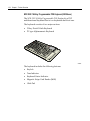
Keyboards ............................................................................................ 1‐18
5932 Keyboards............................................................................. 1‐18
Keyboard Power....................................................................... 1‐18
NCR PS/2 Alphanumeric Big Ticket POS Keyboard (5932‐1xxx) ................................................................................ 1‐19
NCR 64‐Key PS/2 POS Keyboard (5932‐2xxx) ..................... 1‐20
iv
NCR USB Alphanumeric Big Ticket Keyboard (5932‐
5xxx) ........................................................................................... 1‐23
NCR 5932 104‐Key Programmable POS Keyboard (5932‐
6xxx) ........................................................................................... 1‐24
Customer Displays.............................................................................. 1‐25
7446‐K451 VFD ............................................................................. 1‐25
5972‐1xxx VFD .............................................................................. 1‐27
5972‐2xxx LCD .............................................................................. 1‐28
Printers ................................................................................................. 1‐29
7162 Printer.................................................................................... 1‐29
7167 Printer.................................................................................... 1‐29
7197 Printer.................................................................................... 1‐30
System Configuration Diagram ........................................................ 1‐31
Wireless Network ............................................................................... 1‐32
Introduction to Using Access Points.......................................... 1‐32
Chapter 2: Hardware Installation
Installation Restrictions........................................................................ 2‐1
Base Terminal ........................................................................................ 2‐2
Keyboard and Mouse Connections .................................................... 2‐3
Installing the Transaction Printer ....................................................... 2‐4
Installing the Operator Display .......................................................... 2‐7
5942 LCD Monitor .......................................................................... 2‐7
5982 5‐Inch Operator Display ....................................................... 2‐9
Installing the PCI LCD Card (5952‐K052)............................. 2‐10
Connecting the 5982 Display to the Terminal...................... 2‐11
CRT................................................................................................. 2‐12
Installing an Integrated Customer Display ..................................... 2‐13
Installing a Remote NCR 7446‐K451 Customer Display ............... 2‐19
v
Installation Procedure ........................................................................ 2‐20
Installing a Remote NCR 5972 Customer Display ......................... 2‐25
5972 Customer Display ........................................................... 2‐25
Installing the Display Mount.................................................. 2‐26
Installing a Cash Drawer ................................................................... 2‐27
Chapter 3: Setup
Entering Setup ....................................................................................... 3‐1
How to Select Menu Options .............................................................. 3‐1
Special DynaKey Keypad Mode ......................................................... 3‐2
Normal DynaKey Keypad Operating Mode .............................. 3‐4
Disabling Resources.............................................................................. 3‐4
BIOS Default Values ............................................................................. 3‐5
Standard CMOS Features.............................................................. 3‐5
Advanced Features......................................................................... 3‐6
Advanced Chipset Features .......................................................... 3‐7
Integrated Peripherals ................................................................... 3‐7
Power Management Setup ............................................................ 3‐9
PnP/PCI Configurations .............................................................. 3‐10
Chapter 4: Operating System Recovery
Introduction ........................................................................................... 4‐1
Prerequisites .................................................................................... 4‐1
OS Recovery........................................................................................... 4‐2
Connecting an External USB CD‐ROM Drive ............................ 4‐2
Recovery Procedures...................................................................... 4‐3
Completing the OS Installation........................................................... 4‐4
Windows XP Pro/Windows XPe .................................................. 4‐4
DOS................................................................................................... 4‐4
vi
Gold Disk Contents............................................................................... 4‐5
NCR 7446‐xxxx (WinXP Pro) OS Recovery Software (LPIN: D370‐0635‐0100) ................................................................. 4‐5
NCR 7446‐xxxx (WinXPe) OS Recovery Software (LPIN: D370‐0619‐0100).............................................................................. 4‐1
OS Customization ...................................................................... 4‐2
Chapter 5: BIOS Updating Procedures
Introduction ........................................................................................... 5‐1
Prerequisites .................................................................................... 5‐1
Creating the Bootable Media ........................................................ 5‐2
Creating a Bootable Flex Diskette ............................................ 5‐2
Creating a Bootable CD ............................................................. 5‐2
BIOS Update .......................................................................................... 5‐3
Connecting an External USB CD‐ROM Drive ............................ 5‐3
Updating Procedures ..................................................................... 5‐4
Chapter 6: 2x20 Customer Display (7446‐K451)
Features .................................................................................................. 6‐1
General Specifications .......................................................................... 6‐2
Interface.................................................................................................. 6‐3
Specifications................................................................................... 6‐3
Connector Pinouts .......................................................................... 6‐4
RS232C Link to PC/HOST Connector ..................................... 6‐4
Display Panel Connector........................................................... 6‐4
Dip Switch and Software Setting ........................................................ 6‐5
Command Type Selection ............................................................. 6‐5
Baud Rate Selection ........................................................................ 6‐5
Parity Check Selection ................................................................... 6‐5
vii
Demo Mode Selection .................................................................... 6‐5
International Character Set ........................................................... 6‐6
Command Control.......................................................................... 6‐7
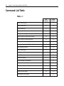
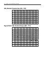
Command List Table ............................................................................ 6‐8
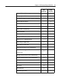
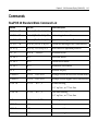
Commands........................................................................................... 6‐11
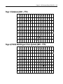
RealPOS 20 Standard Mode Command List............................. 6‐11
EPSON ESC/POS Command List‐1............................................ 6‐13
EPSON ESC/POS Command List‐2............................................ 6‐15
Set International Font for ESC/POS (Table 7‐11) ................. 6‐16
Select Code for ESC/POS (Table 7‐12) ................................... 6‐16
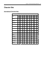
Character Sets ...................................................................................... 6‐17
International Character Sets........................................................ 6‐17
USA, Standard Character Sets (20H – 7EH) ............................. 6‐18
Page 0 (PC437: USA, Standard Europe) (80H – FFH) ............. 6‐18
Page 1 (Katakana) (80H – FFH) .................................................. 6‐19
Page 2 (PC858: Multilingual+ Euro Symbol) (80H – FFH)...... 6‐19
Page 3 (PC860: Portuguese) (80H – FFH).................................. 6‐20
Page 6 (Slavonic) (80H – FFH) .................................................... 6‐20
Page 7 (Russia) (80H – FFH) ....................................................... 6‐21
Command details ................................................................................ 6‐22
Overwrite Mode ........................................................................... 6‐22
Vertical Scroll Mode..................................................................... 6‐22
Horizontal Scroll Mode ............................................................... 6‐22
Set the String Display Mode, and Write String to Display..... 6‐23
Upper Line Message Scroll Continuously ................................ 6‐23
Move Cursor Left.......................................................................... 6‐23
Move Cursor Right....................................................................... 6‐24
Move Cursor Up ........................................................................... 6‐24
Move cursor down ....................................................................... 6‐25
viii
Vertical scroll................................................................................. 6‐25
Move Cursor to Home Position.................................................. 6‐25
Move Cursor to Left‐Most Position ........................................... 6‐25
Move Cursor to Right‐Most Position......................................... 6‐25
Move Cursor to Bottom Position................................................ 6‐25
Move Cursor to Specified Position ............................................ 6‐26
Initialize Display........................................................................... 6‐26
Reset the Window ........................................................................ 6‐26
Clear Display Screen, and Clear String Mode .......................... 6‐26
Clear current line, and cancel string mode ............................... 6‐26
Brightness adjustment ................................................................. 6‐26
Set cursor ON or OFF................................................................... 6‐26
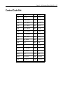
Control Code Set ................................................................................. 6‐27
Code Example...................................................................................... 6‐28
Chapter 7: Cash Drawer Interface
Software Drivers ................................................................................... 7‐1
Cash Drawer Pin Assignment ............................................................. 7‐1
Cash Drawer Controller register description.................................... 7‐2
Cash Drawer Control Register...................................................... 7‐2
Cash Drawer Status Register ........................................................ 7‐3
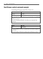
Cash Drawer control command example .......................................... 7‐4
Code Example........................................................................................ 7‐5
Appendix A: Cables
Printer Cables .......................................................................................A‐1
Printer Power Cable (24V)............................................................A‐1
RS‐232 (9‐Pin to 9‐Pin) ..................................................................A‐1
RS‐232 (9‐Pin to 25‐Pin) ................................................................A‐2
ix
Standard USB .................................................................................A‐2
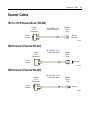
Scanner Cables......................................................................................A‐3
7872 or 7875 Scanner/Scale (RS‐232) ...........................................A‐3
7892 Scanner (Powered RS‐232) ..................................................A‐3
7882 Scanner (Powered RS‐232) ..................................................A‐3
7837 Scanner (Powered RS‐232) ..................................................A‐4
7837 Scanner (RS‐232, External Power) ......................................A‐4
Display Cables......................................................................................A‐5
VGA Display, Mono......................................................................A‐5
VGA Display, Color ......................................................................A‐5
CRT AC Power Extension ............................................................A‐5
5942 12.1 Inch LCD........................................................................A‐6
5982 5‐Inch LCD ............................................................................A‐6
5972 VFD Customer Display (Powered RS‐232) .......................A‐6
Ethernet, 10/100BaseT Cable ..............................................................A‐7
PS/2 Keyboard Extension Cable.........................................................A‐7
Signature Capture/Electronic Payment Terminal Cable ................A‐7
5945/5992 EPT (RS‐232 w/Power)................................................A‐7
Power Cables ........................................................................................A‐8
AC Power........................................................................................A‐8
Appendix B: Memory Maps
x
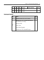
Revision Record
Issue
Date
Remarks
A Mar 2004 First issue Safety and Regulatory Information
The NCR RealPOS 7443 conforms to all applicable legal requirements. To view the compliance statements see the NCR RealPOS Terminals Safety and Regulatory Statements (B005‐0000‐1589). Chapter 1:
Product Overview
The NCR RealPOS™ 30 (also known as NCR 7446) is a powerful, retail‐
hardened point‐of‐sale terminal targeted for general merchandise, food and convenience store environments. It provides exceptional scalability utilizing 1.2GHz Intel Celeron processor to address a range of price/performance levels and operating system environments. The system offers superior connectivity for retail, with support for legacy peripheral interfaces (RS‐ 232, PS/2, Parallel, and VGA), as well as emerging interface standards such as USB 1.1 ports. The optimized cabinet configurations save valuable space at the Checkstand while providing expandability for future needs. The system includes 1 PCI slot, 2 DIMM memory sockets supporting up to 512 MB of PC133 SDRAM. There are provisions for internal Flex Disk Drive and Compact Flash Memory devices. The RealPOS 30 supports a broad range of industry standard operating system environments including DOS and Windows XP Embedded. In addition, the RealPOS 30 is Linux certified utilizing various Linux distributions. Note: Windows 2000 Professional and Linux reference images are also available by special request. You may order NCR drivers on CD‐ROM, but they must be loaded or configured by the customer. 1-2
Chapter 1: Product Overview
Configuration
Modular Configuration
The RealPOS 30 is the smallest terminal cabinet in the RealPOS family. Integration options are limited to the 7446‐K300 Rear Cable Cover, which offers support for an optional pole‐mounted display. Note: The RealPOS 30 does not support unified configurations. The devices cannot be stacked on a single peripheral tray. Since the keyboard location is in front, this prevents the terminal from integrating on a cash drawer. 21471
Chapter 1: Product Overview
1-3
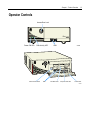
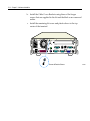
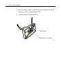
Operator Controls
Access Door Lock
R eal
Power ON LED
Disk Activity LED
Power On/Off switch
USB
USB
Fiex Disk Drive
21580
Compact Flash Slot
Access Door
21579
1-4
Chapter 1: Product Overview
Serial Number/Model Number Label
The serial number and model number are included on a label, which is located at the bottom of the unit. A Certificate of Authenticity label is also included if the terminal was shipped with a pre‐installed Operating System. Note: Place Label On
Bottom Of Unit
NCR Corporation
Atlanta, GA 30096
Class 7456
Model No: xxxx
Serial No: 54-xxxxxxxx
Date of Mfg. 04/10/02
I. T. E.
E152553
Certificate of Authenticity
Made in Singapore
100-240 Vac 6.0 A 50-60 Hz
ACN 000 003 592
This device complies with Part 15 of the FCC rules.
Operation is subject to the following two conditions:
(1) this device may not cause harmful interference, and
(2) this device must accept any ionterference received,
including interference that may cause indesired operation.
This Class A digital apparatus complies with
Canadian ICES-003
Get Appareli numeriqe de la classe A est
conformo a la normo NMB-003 ju Canada
NO.437
Windows 2000 Pro Embedded 1-2 CPU
Product Key:
H95X7-83WVV-CFCWW-M4MXX7-X6XGM
00019-068-654-234
21582
Note: Another serial number label also appears inside the media door (door on front bezel protecting access to the Flex Disk Drive and power switch). Chapter 1: Product Overview
1-5
Features
Processor Board
The processor board has the following features: •
1.2GHz Intel Celeron processor with 100MHz front side bus •
Two 168‐Pin DIMM memory sockets (up to 512 MB of PC133 SDRAM) •
One Combo PCI Riser Slot for Optional Expansion Card •
Four External RS‐232 ports (selectable) •
Four UHCI USB 1.1 Ports (two on Back Panel, two on Front Panel) •
Ethernet 10/100baseT LAN •
One Compact Flash Type I Socket on Secondary IDE Channel (Front Panel) •
One 40‐pin Primary IDE Connector (Ultra ATA 33/66/100 Bus Master) •
One 44‐pin Secondary IDE Connector (Ultra ATA 33 Bus Master) •
One 34/26‐pin FDD Connector for Standard/Slim type FDD •
One 40‐pin Connector for POS IO Board which has COM3/4, cash drawer kick out, and 24 V printer power ports •
15‐pin D‐shell connector for CRT or analog LCD •
25‐pin D‐shell Parallel connector •
1.44 MB Flex Disk interface •
Audio out •
PS/2 Keyboard Port •
PS/2 Mouse Port •
Integrated Graphics controller Multiplexed with AGP Controller •
Up to 32MB Shared Video Memory—Unified Memory Architecture (UMA) •
Two Fan connectors for CPU/System with FAN Control 1-6
Chapter 1: Product Overview
•
APM 1.2 or ACPI 1.0b •
2Mbit LPC Firmware Hub for Award BIOS •
Real‐Time Clock/Calendar 256‐byte CMOS •
2Mbit LPC Firmware Hub for Award BIOS I/O POS Board
The functions and capabilities include: •
Two D‐Sub 9‐pin for two 16550 compatible UARTs (COM3/COM4) with power selection jumpers •
One RJ11 Cash drawer port •
One +24V Port for a POS Printer •
On board +12V to +24V DC/DC converter for cash drawer power selection •
40‐pin Connector for connection to the Main Board •
4‐pin power connector Combo Riser Card
•
One Combo PCI Riser slot for optional expansion •
33 MHz, 5V, 32 bit •
Maximum length for PCI cards is 150mm (5.9 in.) •
PCI‐2.2 compliant •
3.5‐Inch Flex Disk Drive •
3.5‐Inch Hard Disk Drive •
64MB or 256MB Compact Flash (through IDE interface) Storage Media
Chapter 1: Product Overview
1-7
Power Supply
•
180W Output power •
Active Power Factor Correction (PFC) circuit •
Auto‐ranging input features •
100‐127VAC or 200‐240 VAC, 50‐60Hz Operating Systems
•
DOS 6.22 •
Windows XPe •
Windows XP Pro Note: A Linux reference image, including NCR drivers, is orderable on CD‐ROM, but must be loaded or configured by customer. You may separately negotiate with NCR Worldwide Customer Services or NCR Professional Services for custom preloading services, including Windows XP Professional, Windows 2000 and Linux. 1-8
Chapter 1: Product Overview
Power Management
Power management is implemented on the 7446 using the ACPI 1.1 Specification 1.1. In order to accomplish this, the processor board is equipped with ACPI BIOS. The BIOS supports the ACPI 1.1 specification. This permits the terminal to go to a low power state during some level of inactivity. With ACPI, the operating system has some control over the power management by going into suspend, standby, or hibernate (depending on the Operating System). The S0, S1, S4, and S5 states are implemented. For the detail of the ACPI, refer to ACPI Specification 2.0b. Not all Entry and Exit points are available at all times. Availability is based on ACPI states. Notes:
•
When the LAN cable is connected a WakeOnLan notification is sent to the operating systems, causing the terminal to come out of a low power state such as hibernation under Windows 2000/Windows XP. This is similar to the WakeOnLan feature. •
Wake on Alarm is not supported from the ʺoffʺ state. This is because the ACPI power management in the BIOS does not allow the Timer/Alarm to wake the system. Wake on LAN is supported. Similar functionality can be implemented from the server by sending a LAN wakeup message. •
Wake on Alarm from Window NT is not supported. •
USB devices must be enabled in Windows 2000/Windows XP for Wake from Standby to function. This is set in at: Start Æ Control Panel Æ System Æ Hardware Tab Æ Device Manager Æ [USB device] Æ Properties. There is a check box to enable the function under the USB tab. Chapter 1: Product Overview
1-9
Definitions of the states involved
Mechanical Off: System is not working. No AC power is connected to the system. Operational parameters are not saved. System resets and initializes when transitioning to the Full On State. Entry: a) Remove power from unit. Exit: Connect power to unit. (move to Soft Off or Full On or APM Enabled) Soft Off: AC Power is connected to the system. Only the 5V standby and 3.3V standby voltages are present within the machine. Entry: a) Connect power to unit. (Assuming “Status after power fail” in BIOS Setup is configured for “Off” after power cycle or it is configured for “Previous Status” and the previous status was off when AC power was removed. b) Turn off unit via power button. Power button can be configured for either instant off or for off after being pressed for longer than four seconds. c) Unit turned off via software control Exit: a) Press power button b) Wake On LAN (*) c) Wake ON Ring (*) d) Wake On Alarm (*) e) Remove AC Note: Function has no effect with any of the following conditions: a) First time AC is connected b) Power button delay is set to 4 seconds into Soft Off state c) BIOS is not set to enable these functions 1-10
Chapter 1: Product Overview
Full On: System is working and not power managed (APM Disabled) Entry: a) Press power button. b) Wake On LAN c) Wake On Ring d) Wake On Alarm Exit: a) Turn off unit via power button. Power button can be configured for either instant off or for off after being pressed for longer than four seconds. b) Unit turned off via software control c) Remove AC APM Enabled: System is working and not power managed Entry: a) Press power button b) Wake On LAN c) Wake On Ring d) Wake On Alarm e) Wake on PS/2 keyboard or PS/2 mouse activity f) Wake on USB activity Exit: a) Turn off unit via power button. Power button can be configured for either instant off or for off after being pressed for longer than four seconds. b) Unit turned off via software control c) Disable APM c) Remove AC Chapter 1: Product Overview
1-11
APM Standby •
System is in a low power state with some power savings •
Most devices are in a low power mode. •
The CPU clock is slowed or stopped. •
Operational parameters are retained. •
System returns quickly to the APM Enabled State. •
The Resume Timer event must return the system to the APM Enabled state. •
User activity may be required to return the system to the APM Enabled State. •
The operating system is notified after the system transitions to the APM Enabled State. •
Prior operation resumes after returning to the APM Enabled state. •
Interrupts must still be processed normally. This may require waking up the CPU temporarily if it was stopped. •
The CPU may be stopped again when the APM Driver calls the CPU Idle function. Some (not all) specific device states: •
Hard Drive: Standby (motor not spinning, interface buffer active) •
Display: CRT – Suspend (No image on screen, LCD – Off •
Video Controller: Standby •
Chipset: Standby Entry: a) Programmable timeout b) Under software control Exit: a) Wake On LAN c) Wake ON Ring d) Wake On Alarm e) Wake on PS/2 keyboard or PS/2 mouse activity 1-12
Chapter 1: Product Overview
f) Wake on USB activity g) Remove AC APM Suspend: System is in a low power state with maximum power savings. Most power managed devices are not powered. The CPU clock is stopped. The CPU core is in its minimum powered state. Operational parameters are saved to be restored later when resuming. System takes a relatively long time to return to the APM Enabled state. The Resume Timer event must be on of the wakeup events. The operating system is notified after the system transitions to the APM Enabled state. Prior operation resumes after returning the APM Enabled state. Some (not all) specific device states: •
Hard Drive: Sleep (motor not spinning, interface buffer inactive) •
Display: CRT – Off, LCD – Off •
Video Controller: Suspend •
Chipset: Suspend Entry: a) Programmable timeout b) Under software control Exit: a) Wake On LAN b) Wake On Ring c) Wake On Alarm d) Wake on keyboard, mouse, or touch activity e) Wake on USB activity f) Remove AC The APM BIOS provides some degree of power management functionality without any support from the operating system or application software. Chapter 1: Product Overview
1-13
An APM driver is better suited to make power management decisions for unique peripherals than the BIOS, and can override most BIOS requests to go into standby, suspend, and so on. APM device drivers provided by NCR with the RealPOS 30 are outlined in the Retail TAPS Programming Help File (BD90‐0261‐B). Terminal power on/power off is controlled through a logic level power switch on the processor board. It can be disabled through software. 1-14
Chapter 1: Product Overview
Operator Displays
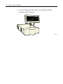
5942 12.1-Inch Color LCD
The design of the 5942 12.1‐Inch LCD is for customers who desire a color display and prefer the small footprint and ergonomic packaging of LCD technology versus traditional CRT’s. The 5942 Display features a 12.1‐Inch Active Matrix Color LCD with support for SVGA and XGA resolution. 19809
Note: The RealPOS 30 supports the 5942 LCD Display as an operator display only. Features
• Bright dual and single backlight active matrix LCDs •
VGA Interface •
Standalone Base •
1.5m VGA Cable •
AC Power Supply with mini‐IEC connector •
AC Power Cord Chapter 1: Product Overview
1-15
5982 5-Inch Monochrome LCD
The 5982 LCD Display is a terminal‐powered monochrome 5‐Inch VGA LCD. It is suitable for retail environments that do not require a significant amount of data displayed at one time, and/or require an operator display with a very small footprint. The display provides a 2x20 display format emulation with a 2x20 VCO driver to facilitate application and hardware migration. It supports off‐the‐shelf operating systems and applications, and can mount on the 5932 64‐Key keyboard or standalone with an 8‐inch Post Mount (5982‐F034). 19744
Features
• Keyboard Mount •
4m LCD Cable Note: To configure a 5982 LCD Display with the RealPOS 30, a PCI LCD Card (5952‐K052) is required. 1-16
Chapter 1: Product Overview
CRT Displays
The RealPOS 30 supports traditional CRT/Keyboard configurations. Note: The display’s data cable connects to the analog VGA port at the back of the terminal. However, ensure a separate order for a power cord to connect the CRT directly to an external AC outlet. There is no AC convenience outlet at the back of the RealPOS 30 terminal. 7452-K404 9-Inch Monochrome CRT (Remote)
7452-K404
19742b
Features
• Non‐glare, phosphor screen with VGA (600x800) resolution •
Table top mount with tilt and swivel •
4m Data (Video) Cable •
4m Power Cables Chapter 1: Product Overview
1-17
7452-K419 15-Inch Color CRT (Remote)
19743
Features
• Non‐glare, phosphor screen with VGA (640x480) resolution •
Table top mount with tilt and swivel •
1m Data (Video) Cable •
1m Power Cables 1-18
Chapter 1: Product Overview
Keyboards
5932 Keyboards
The NCR 5932 Keyboards are intended for harsh retail environments and contain an internal membrane to protect against objects such as paper clips, staple wires, pins, and so forth, from falling between the keys and damaging the electronics. This technology improves overall reliability not typically found in standard PC keyboards or many retail keyboards. There are four models of the NCR 5932 Keyboard: •
NCR PS/2 Alphanumeric Big Ticket POS Keyboard (5932‐1xxx) •
NCR 64‐Key PS/2 POS Keyboard -
without Magnetic Stripe Reader (MSR) (5932‐2xxx) -
with MSR (5932‐2xxx) •
NCR USB Alphanumeric Big Ticket Keyboard (5932‐5xxx) •
NCR 5932 104‐Key Programmable POS Keyboard (5932‐6xxx) Keyboard Power
The RealPOS 80 supplies power to the PS/2 keyboard even when in the OFF state. This is for configurations that require the terminal to turn on when a key is pressed. Most NCR PS/2 keyboards have a Power ON LED which stays illuminated, indicating power is present in the keyboard. Pressing a key may also cause tones to be sounded, but unless the terminal is configured to power up when a key is press, nothing happens. Chapter 1: Product Overview
1-19
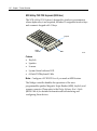
NCR PS/2 Alphanumeric Big Ticket POS Keyboard (5932-1xxx)
This NCR PS/2 Alphanumeric Big Ticket POS Keyboard contains a full alphanumeric keyboard, a POS numeric keypad, and POS Function keys. The function keys permit customer specific key assignments. It also includes a 68‐Inch keyboard cable. Keylock
Status
Indicator
MSR
19745
Features
• 3‐Track ISO Magnetic Stripe Reader (MSR) •
68‐Inch PS/2 Keyboard Cable •
International English Character Set Wedge support for the following: •
Keylock •
Speaker •
Scanner •
MSR 1-20
Chapter 1: Product Overview
NCR 64-Key PS/2 POS Keyboard (5932-2xxx)
The NCR 64‐Key POS Keyboard, designed for checkout environments where alpha entry is not required, includes 55 assignable function keys and a numeric keypad with 11 keys. Keylock
Status
Indicator
MSR
19746
Features
• Keylock •
Speaker •
Scanner •
System Status Indicator LED •
68‐Inch PS/2Keyboard Cable Note: Configure a NCR 5932‐2xxx if you need an MSR feature. The Wedge controller handles the operations of the user‐
programmable speaker, Magnetic Stripe Reader (MSR), keylock, and scanner connector. Please refer to the Wedge Software User’s Guide (BD20‐1368‐A) for detailed information about interfacing and configuring these devices. Chapter 1: Product Overview
1-21
Keylock
The Big Ticket and 64‐key keyboards have a four‐position keylock switch. The table following explains the keylock positions. Abbreviation Position
Description
Ex Exception Used by the customer or service representative to perform low‐level programming such as terminal diagnostics, configuring the terminal, or loading the terminal. L Locked Used to lock keyboard input to prohibit use of normal functions. R Register Used when performing normal retail mode functions. S Supervisor Used by supervisor to provide highest level of terminal control in cases such as refunds and running totals. Speaker
A programmable speaker generates key clicks and error tones. Buzzer
The buzzer is an internal on board Buzzer. System Status Indicator LED
The system status indicator is a two‐color LED. The green color indicates the keyboard has power. Red indicates an error condition. When the system is off, the LED does not light up. When the 64‐key keyboard is in the special PC setup mode, the LED flashes red/green. 1-22
Chapter 1: Product Overview
The status and condition indicated by the LED are as follows: Status
Condition
Green Power on Red Wedge controller reporting an error condition Flashing red/green Keypad of 64‐key keyboard in PC Setup mode Off System off (see Keyboard Power section) Note: For more information about the Wedge controller, refer to Wedge Software User’s Guide (BST0‐1368‐B). MSR (Magnetic Stripe Reader)
The MSR is an optional feature that provides support for reading magnetically coded data cards. The keyboards support two different types of MSR: •
ISO Tracks 1, 2, and 3 •
JIS‐II and ISO Track 2 (Big Ticket and full‐featured 64‐key keyboards only) Note: MSR signals are routed to the Wedge controller and passed into the system keyboard data stream. For more information about the Wedge controller, refer to Wedge Software User’s Guide (BD20‐1368‐A) Chapter 1: Product Overview
1-23
NCR USB Alphanumeric Big Ticket Keyboard (5932-5xxx)
Keylock
MSR
19586
The NCR USB Alphanumeric Big Ticket Keyboard is a multifunction keyboard that is two keyboards built into one. The keyboard consists of two major sections: •
38‐key POS keyboard •
Industry‐standard alphanumeric PC keyboard The keyboard contains the key matrix and other POS‐specific functions such as keylock, speaker, system status indicator, and magnetic stripe reader (MSR). This 5932 keyboard also has a USB port to connect a Scanner or other USB device. Features
The NCR 5932 USB Keyboard supports the following features: •
Integrated Touch Pad, Keylock, Speaker, 3‐Track Magnetic Stripe Reader (MSR) •
Keyboard Status LEDs •
USB cable •
Additional external USB ports •
No language characteristics Note: Refer to NCR 5932 USB Keyboard User’s Guide (B005‐0000‐1395) for further detailed information. 1-24
Chapter 1: Product Overview
NCR 5932 104-Key Programmable POS Keyboard (5932-6xxx)
The NCR 5932 104‐Key Programmable POS Keyboard is a PS/2 multifunctional keyboard that is two keyboards built into one. The keyboard consists of two major sections: •
32‐key Point‐Of‐Sale Keyboard •
PC type Alphanumeric Keyboard 21662
The keyboard includes the following features: •
Keylock •
Tone Indicator •
Keyboard Status Indicator •
Magnetic Stripe Card Reader (MSR) •
Glide Pad Chapter 1: Product Overview
1-25
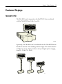
Customer Displays
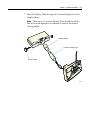
7446-K451 VFD
The 7446‐K451 can be integrated on the RealPOS 30 when combined with the 7446‐K300 Rear Cable Cover Kit. 21679a
Optionally, the 7446‐K451 can be combined with the 7446‐K452 Remote Base Kit to become a free‐standing remote display. The remote base kit includes two posts, which provide a variety of height options ranging from 20 – 51 cm (7.8 – 20 in.). 21677
1-26
Chapter 1: Product Overview
Features
• 5 x 7 pixel characters -
international (single‐byte) characters sets -
Euro •
OPOS drivers available for supported Windows O/S •
Adapter, mounts to rear base with 2 screws (only screws required) •
11.5cm short extension post •
25cm long extension post •
50 cm RS‐232 cable (integrated) •
Sturdy plastic base with 4 screw mounts for attaching base to countertop (Remote) •
2m RS‐232 cable (Remote) •
Terminal Powered Chapter 1: Product Overview
5972-1xxx VFD
The NCR 5972‐1xxx Display is a 2x20 alphanumeric VFD display. It requires selection of cable feature, power feature and remote mount feature to configure with the RealPOS 30. Desktop Model
16-Inch Post
Features
• RS‐232 Interface •
Socket for 32K of PROM for additional character sets •
7 x 9 pixel characters •
Diagnostics •
Character sets: •
•
Code Page 858 (International) •
Katakana •
Code Page 866 (Cyrillic) Terminal Powered or external power supply 20448
1-27
1-28
Chapter 1: Product Overview
5972-2xxx LCD
The NCR 5972‐2xxx is a low cost alphanumeric 2x20 LCD Display. It requires a selection of remote mount feature to configure with the RealPOS 30. 5972-2xxx (LCD)
5972-2xxx (LCD)
19750c
Features
• RS‐232 Interface •
5 x 8 pixel characters •
Diagnostics •
Character sets: •
•
Code Page 858 (International) Terminal Powered or external power supply Chapter 1: Product Overview
1-29
Printers
7162 Printer
The NCR 7162 is a dot matrix printer that provides up to 40 columns receipt and journal, and up to 88 columns of slip print. The printer’s features include paper low sensors, slip‐out detectors, automatic paper cutting, and two cash drawer kick out connectors. It has an RS‐232 data interface. It receives power from the 24V connector on the terminal I/O Board or from an external power supply.. It also has a connector for cash drawers. 15220
Note: Printer data cable is not included with the printer. 7167 Printer
The NCR 7167 Printer is a fast, quiet, relatively small and very reliable multi‐function printer. It prints receipts, validates and prints checks, and prints on a variety of single or multiple part forms. There is no journal as the host terminal keeps it electronically. The printer can connect through a USB port or a serial port. It receives power from the 24V connector on the terminal I/O Board or from an external power supply.. 1-30
Chapter 1: Product Overview
19711
Note: Printer data cable is not included with the printer. 7197 Printer
The NCR 7197 Printer is a fast, quiet, relatively small and very reliable multi‐function printer. It prints receipts and is capable of two‐color printing. The printer can connect through a USB port or a serial port. It receives power from the 24V connector on the terminal I/O Board or from an external power supply. 19712
Note: Printer data cables is not included with the printer. Chapter 1: Product Overview
1-31
System Configuration Diagram
7892
7882
7837
CRT-K4xx
5972 or 7446-K451
5942
5982
5932-5xxx
Big Ticket USB
PCI LCD Card USB
RS-232) USB VGA
USB
7167
7197
7162
RS-232
USB
RS-232
I/O POS
Board
LAN
7446 Motherboard
24V Power
Parallel
Cash
Drawer
2182/2183/2189
Audio Jack
5932-6xxx
Compact
PS/2
5932-1xxx
Big Ticket
5932-2xxx
64-Key
PS/2
RS-232
PS/2
Mouse
5972-2500
7197
5972-1200
7875
7167
7162
5972 or 744x-K542
21607
1-32
Chapter 1: Product Overview
Wireless Network
The 7446 supports the ORiNOCO 802.11b Gold PCI Adapter (2330‐
K354) wireless network component. This wireless LAN PCI expansion card features Gold 128‐bit encryption and worldwide certification. Note: Maintenance is not offered for the 2330‐K354 due to rapid product refresh cycles in the wireless industry. Introduction to Using Access Points
An Access Point extends the capability of an existing Ethernet network to devices on a wireless network. Wireless devices can connect to a single Access Point, or they can move between multiple Access Points located within the same vicinity. As wireless clients move from one coverage cell to another, they maintain network connectivity. Access
Point
Coverage
Area
Hub
Access
Point
21136
Wireless Network Access Infrastructure To determine the best location for an Access Point, it is best that you conduct a Site Survey before placing the device in its final location. For information about how to conduct a Site Survey, contact your local NCR support representative. Chapter 1: Product Overview
Before configuring an Access Point for your specific networking requirements, ensure initialization. See the ORiNOCO AP‐2000 User Guide (2330‐K309) details. This document is available on the NCR Information Products web site at http://www.info.ncr.com. Click on General Search and then enter Proxim in the Title field. 1-33
Chapter 2:
Hardware Installation
This chapter explains how to install the RealPOS 30 hardware, including out‐of‐box installation and how to install the optional peripheral devices. The 7446 is very flexible to install. This document discusses a typical configuration. Your configuration may require adjustments to the procedures. Installation Restrictions
•
Before installing the RealPOS 30, read and follow the guidelines in the RealPOS 30 Site Preparation Guide (B005‐0000‐1552) and the NCR Workstation and Peripheral AC Wiring Guide (BST0‐2115‐53). •
Install the RealPOS 30 near an electrical outlet that is easily accessible. Use the power cord as a power disconnect device. •
Do not permit any object to rest on the power cord. Do not locate the RealPOS 30 where the power cord can be walked on. •
Use a grounding strap or touch a grounded metal object to discharge any static electricity from your body before servicing the RealPOS 30. Caution: This unit contains hazardous voltages and should only be serviced by qualified service personnel. Caution: Do not connect or disconnect the transaction printer while the terminal is on. This can result in system or printer damage. 2-2
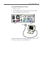
Chapter 2: Hardware Installation
Base Terminal
1. Unpack the terminal in the desired location. 2. Connect the external cables. The following illustration identifies the Back Panel and Front Panel cable connectors (I/O POS Board is shown). 21240
Audio Out
24V Power
USB 1
RS-232/4
Mouse
USB 2
Parallel
Keyboard
RS-232/2
Cash Drawer
RS-232/1
RS-232/3
VGA
LAN
R eal
USB 3
USB 4
21581
Chapter 2: Hardware Installation
2-3
Keyboard and Mouse Connections
The keyboard and mouse directly connects to the terminal through the PS/2 connectors. A PS/2 connector is available for each. 21583
2-4
Chapter 2: Hardware Installation
Installing the Transaction Printer
The NCR 7162, NCR 7167 and NCR 7197 printers connects to the terminal directly or as remote devices. Other printers are available as remote devices only. The printers can connect through a USB connector or an RS‐232 connector. Interfaces Supported
Printer
USB
RS-232
7162 √ 7167 √ √ 7197 √ √ Chapter 2: Hardware Installation
2-5
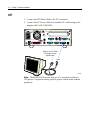
1. Connect the Data Connector Cable (USB or RS232) on the printer to the corresponding terminal port. 2. Connect the Printer Power Cable to the Power Connector on the printer and to the 24V Power Connector on the terminal. Power
RS-232
497-0435073 - 2 m
(1416-C984-0020)
9-Pin to 25-Pin (7162) 9-Pin to 9-Pin
497-0407427 - 1.0 m 497-0408349 - 0.7 m
(1416-C337-0010)
(1416-C359-0007)
497-0407429 - 4 m
(1416-C337-0040)
497-0407943 - 4 m
(1416-C266-0040)
21584
2-6
Chapter 2: Hardware Installation
R eal
USB
497-0418587 - 1 m
(1416-C640-0010)
Power
497-0435073 - 2 m
(1416-C984-0020)
497-0418588 - 4 m
(1416-C640-0040)
21585
Chapter 2: Hardware Installation
2-7
Installing the Operator Display
You may place an Operator Display directly on top of the base terminal. When there is no Customer Display the recommended location for the Operator Display is the back position, thus minimizing the overhang of the display. The 7446 supports the following Operator Displays. •
NCR 5942 LCD Monitor •
NCR 5982 5‐Inch Mono LCD •
NCR 7452‐K404 9‐Inch CRT (Remote) •
NCR 7452‐K419 15‐Inch Color CRT (Remote) 5942 LCD Monitor
The 5942 connects to the terminal through the VGA connector. It receives power from an AC power supply. 2-8
Chapter 2: Hardware Installation
VGA
Power
VGA
21586 1. Connect the LCD Cable to the VGA connectors on the 5942 monitor and RealPOS 30 terminal. 2. Connect the power to the monitor by connecting the AC Power Supply to a standard AC outlet using an AC adapter cable (1416‐C508‐0040). Chapter 2: Hardware Installation
2-9
5982 5-Inch Operator Display
The 5982 5‐Inch Operator Display is a 640 x 480 LCD with a backlight (not adjustable), contrast control knob, and keyboard mount. 19744
Note: Before the 5982 Display is connected, the PCI LCD board must be installed in the terminal. 2-10
Chapter 2: Hardware Installation
Installing the PCI LCD Card (5952-K052)
1. Power the system OFF. 2. Set SW1 to select Panel 4 (see chart below). Panel Select Switch
(SW1)
Power Harness Connector
Keyboard Header Connector
(for optional internal harness)
VGA BIOS
LCD Connector
PS/2 Keyboard Connector
(Keyboard Adapter Cable)
15376
P1
P2
P3
Function
OFF OFF OFF Panel 8 (Color DSTN) (Default) OFF OFF ON Panel 7 (Mono STN) OFF ON OFF Panel 6 (Color TFT) OFF ON ON Panel 5 (Unused) ON OFF OFF Panel 4 (5‐in. Mono) ON OFF ON Panel 3 (Unused) ON ON OFF Panel 2 (Unused) ON ON ON Panel 1 (Unused) 3. Install the PCI LCD Board into one of the PCI slots in the terminal. Caution: Use care so as not to damage the Speaker or Keyboard Header connectors on the Motherboard during card installation. Chapter 2: Hardware Installation
2-11
Connecting the 5982 Display to the Terminal
1. Unplug AC power. 2. Locate the Display Mount within 4 meters of the host terminal. 3. Connect the Display Cable to the PCI LCD. PCI LCD
21587
For additional installation information, refer to the NCR 5982 5‐Inch LCD Operator Display Userʹs Guide (BD20‐1443‐A). 2-12
Chapter 2: Hardware Installation
CRT
1. Connect the CRT Data Cable to the VGA connector. 2. Connect the AC Power Cable to a standard AC outlet using an AC adapter cable (1416‐C508‐0040). Plug into an AC Outlet
(Using the country
specific cord)
Data
21590
Note: The RealPOS 30 does not offer an AC convenience outlet for CRT power. A separate country‐specific power cord must be ordered separately. Chapter 2: Hardware Installation
2-13
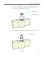
Installing an Integrated Customer Display
The Integrated Customer Display consists of two kits: •
NCR 7446‐K451 Customer Display Kit •
NCR 7446‐K300 Cable Cover Kit 1. Install the Cable Cover Kit. a. Remove the screws (5) from the rear of the terminal. Discard the four silver screws and keep the black screw (upper left‐hand corner). Screws
21466
2-14
Chapter 2: Hardware Installation
b. Install the Cable Cover Brackets using three of the longer screws that are supplied in the kit and the black screw removed earlier. c. Install the remaining kit screw and plastic sleeve in the top center of the terminal. Screw w/Plastice Sleeve
21466
Chapter 2: Hardware Installation
2-15
2. Remove the Display Post Insert and Screw Hole Fillers from the Cable Cover. These are easily pressed out. Display Post Insert
Screw Hole Fillers (4)
21664
3. Install the Inner Post Mount on the Cable Cover with screws (2). Inner Post Mount
21663
2-16
Chapter 2: Hardware Installation
4. Install the Outer Post Mount on the Cable Cover with screws (4). Outer Post Mount
21644
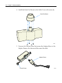
5. Unscrew the Tension Screw that secures the Adapter Sleeve to the display. Remove the sleeve and disconnect the cable. Adapter Sleeve
Tension Screw
21685
Chapter 2: Hardware Installation
2-17
6. Route the cable through the Cable Cover and Adapter Sleeve. 21666
7. Connect the cable and install the Adapter Sleeve in the display, securing it with the Tension Screw. 21667
8. Connect the Display Cable to one of the RS‐232 connectors on the terminal. 2-18
Chapter 2: Hardware Installation
9. Insert the Display into the Cable Cover and then install the assembly onto the terminal. 21679a
Chapter 2: Hardware Installation
2-19
Installing a Remote NCR 7446-K451 Customer Display
This 7446‐K451 Customer Display has various post lengths, which permit different viewing heights for the display.. 21677
2-20
Chapter 2: Hardware Installation
Installation Procedure
The Integrated Customer Display consists of two kits: •
NCR 7446‐K451 Customer Display Kit •
NCR 7446‐K452 Customer Display Remote Base Kit 1. Using the Customer Display Base as a template mark the desired location for the four holes that will be drilled to mount the base. 21687
Chapter 2: Hardware Installation
2-21
2. Remove the Cable Cover if applicable). 3. Unscrew the Tension Screw that secures the Adapter Sleeve to the display. Remove the sleeve and disconnect the cable. Adapter Sleeve
Tension Screw
21685
4. Remove the Base Plate from the Customer Display Base (4 screws). Bottom Plate Screws
21678
2-22
Chapter 2: Hardware Installation
5. Route the Display Cable as shown below and connect it to the RJ connector on the Customer Display PCB. 6. Connect the RS‐232 Cable as shown. RS-232 Cable
Display Cable (RJ Connector)
21671
Chapter 2: Hardware Installation
2-23
7. Route the Display Cable through the Customer Display Post and Adapter Sleeve. Note: There are two Customer Display Posts included in the kit that can be used separately or combined to achieve the desired viewing height. Adapter Sleeve
Customer Display Post
Tension Screw
21673
2-24
Chapter 2: Hardware Installation
8. Connect the cable and install the Adapter Sleeve in the display, securing it with the Tension Screw. 21686
9. Replace the Base Plate on the Customer Display. 10. Connect the RS‐232 Cable to one of the powered RS‐232 connectors on the terminal. Note: The default factory configuration for the RS‐232 ports are: ports 1, 3, and 4 are powered; port 2 is not powered. 11. Connect the other peripheral cables. 12. Re‐Install the Cable Cover on the terminal. 13. Mount the display to the table top using screws (4). Chapter 2: Hardware Installation
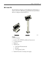
Installing a Remote NCR 5972 Customer Display
There are two models of the 5972 Remote Customer Displays: •
Desktop Model •
Tall Post Model 5972 Customer Display
5972-1xxx (VFD)
5972-1xxx (VFD)
5972-2xxx (LCD)
5972-2xxx (LCD)
19749
19750a
2-25
2-26
Chapter 2: Hardware Installation
Installing the Display Mount
1. Locate the Display Mount within 4 meters (13 ft.) of the host terminal. 2. Determine if the cable should route down through the mounting surface or if it should run on top of the surface. Drill a hole if necessary. 3. High‐Post Mount: If you are installing High‐Post model secure the Mounting Plate with screws (4) provided. Mounting Plate
4.06 mm (0.160 in.) Diameter
7.6 cm
(3.0 in.)
14622
Note: The Mounting Plate illustrated above is for the 5972. 4. Connect the Display Cable to a powered RS‐232 connector on the terminal. Note: The default factory configuration for the RS‐232 ports are: ports 1, 3, and 4 are powered; port 2 is not powered. Audio Out
USB 1
Mouse
USB 2
Parallel
Keyboard
24V Power
RS-232/4
RS-232/2
Cash Drawer
RS-232/1
RS-232/3
VGA
LAN
21589
Chapter 2: Hardware Installation
2-27
Installing a Cash Drawer
The small dimension of the RealPOS 30 permits the terminal to rest directly on most cash drawers. However, other peripherals like the keyboard or printer may or may not fit. The Cash Drawer can connect to the Cash Drawer connector or to the transaction printer. Note: The 7446 is not designed for integration with any current NCR cash drawer. The 7446 supports the following Cash Drawers: •
2182 Compact Cash Drawer •
2183 Mid‐range Cash Drawer •
2189 Full‐size Cash Drawer The Cash Drawer can be connected to the Back Panel on the 7446 or to the Cash Drawer Connector on the transacation printer. Cash Drawer Connector
21592
2-28
Chapter 2: Hardware Installation
Cash Drawer Connector
20440
Note: The RealPOS 30 does not support dual cash drawer configuration. Chapter 3:
Setup
Entering Setup
1. Apply power to the terminal. 2. When you see the NCR logo displayed press [Del] How to Select Menu Options
The following keyboard controls are used to select the various menu options and to make changes to their values. •
Use the arrow keys to select (highlight) options and menu screens. •
Use the [Enter] key to select a submenu. •
Use the [+] and [-] keys to change field values. •
To view help information on the possible selections for the highlighted item, press [F1]. •
To save the changes, move the cursor to the Exit Menu, select either Save Changes & Exit or Save Changes, and press [Enter]. 3-2
Chapter 3: Setup
Special DynaKey Keypad Mode
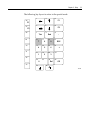
If your Terminal is configured with a DynaKey or Touch Screen module refer to the following sections that discuss special keypad considerations. Otherwise, proceed to the Configuration Setup Procedures section. Many of the Terminal setup routines require keys that are not present in the regular DynaKey keypad layout (such as the ESC and .0END keys). Although the DynaKey has a PC keyboard connector, a PC keyboard may not be readily available to the operator. Note: No setup is required for the DynaKey module itself at installation unless the factory default configuration needs changing. The operational parameters can be changed using the Wedge Configuration Utility (G370‐0701‐0000) diskette or the 7452 Diagnostics and BIOS Images (497‐0406703) diskette. To use the DynaKey without a PC keyboard attached to run the Terminal setup routines, you must place it in the Special DynaKey Keypad Mode. This mode replaces the normal keypad layout and function keys with special key assignments that are required to run setup. To enter the special mode, press the 7 and 9 keys simultaneously during POST diagnostics. Note: The 7 and 9 keys must be the FIRST keys pressed during/after a power up, otherwise the keypad enters the normal layout. Chapter 3: Setup
3-3
The following key layout is active in the special mode. 1
3
2
F1
26
F1
4
6
5
F2
27
F2
28
7
Tab
29
End
11
10
1
34
+
6
20
21
3
2
24
23
0
33
ESC
17
16
32
22
13
5
19
18
-
9
15
14
4
31
12
8
7
30
9
8
Del
25
CR
35
14419
3-4
Chapter 3: Setup
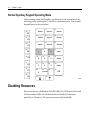
Normal DynaKey Keypad Operating Mode
After running setup the DynaKey can be reset to the normal mode by rebooting or by pressing the 7 and 9 keys simultaneously. The normal keypad layout is shown below. 1
26
3
2
Shift-F1
Shift-F2
Shift-F3
F1
4
27
6
5
Shift-F4
Shift-F5
Shift-F6
F2
7
28
F3
29
30
F5
31
F6
1
32
F8
34
33
0
Cntl-F1
17
6
19
18
13
16
5
4
Shift-F10
9
15
14
22
12
8
7
F7
Shift-F8
11
10
F4
9
8
Shift-F7
20
Cntl-F2
21
3
2
24
23
Shift-F9
Cntl-F3
25
.
CR
35
12389
Disabling Resources
Resources that are disabled in the BIOS (IRQs for COM ports/on‐board LAN/secondary IDE) are still detected and installed (sometimes partially) in Windows. The resources are actually available. Chapter 3: Setup
BIOS Default Values
Standard CMOS Features
System Time
(variable) System Date
(variable) IDE Devices
(variable) Video
[EGA/VGA] Halt On
[All , But Keyboard] 3-5
3-6
Chapter 3: Setup
Advanced Features
External Cache
[Enabled] CPU L2 Cache ECC Checking
[Enabled] Processor Number Feature
[Enabled] Quick Power On Self Test
[Enabled] First Boot Device
[Floppy] Second Boot Device
[HDD‐0] Third Boot Device
[LAN] Fourth Boot Device
[Disabled] Boot Up Floppy Seek
[Disabled] Boot Up NumLock Status
[On] Typematic Rate Setting
[Disabled] * Typematic Rate (Characters/Second)
6 * Typematic Delay (msec)
250 Security Option
[Setup] HDD S.M.A.R.T Capability
[Disabled] Report No FDD For WUB 95
[Yes] Video BIOS Shadow
[Enabled] C8000-CBFFF Shadow
[Disabled] CC000-CFFFF Shadow
[Disabled] D0000-D3FFF Shadow
[Disabled] D4000-D7FFF Shadow
[Disabled] D8000-DBFFF Shadow
[Disabled] DC000-DFFFF Shadow
[Disabled] Chapter 3: Setup
Advanced Chipset Features
SCRAM CAS Latency Time
[Auto] SCRAM Cycle Time Tras/Trc
[Auto] SCRAM RAS to CAS Delay
[Auto] SCRAM RAS Precharge Time
[Auto] CPU Latency Timer
[Enabled] AGP Graphics Aperture Size
[64MB] Integrated Peripherals
Onboard LAN Boot ROM
[Enabled] OnChip IDE Controller
On-Chip Primary PCI IDE
[Enabled] On-Chip Secondary PCI IDE
[Enabled] IDE Primary Master PIO
[Auto] IDE Primary Slave PIO
[Auto] IDE Secondary Master PIO
[Auto] IDE Secondary Slave PIO
[Auto] Primary IDE Max. UDMA
[Auto] IDE Primary Master UDMA
[Auto] IDE Primary Slave UDMA
[Auto] * Secondary IDE Max. UDMA
UMDA 33 IDE Secondary Master UMDA
[Auto] 3-7
3-8
Chapter 3: Setup
IDE Secondary Slave UMDA
Onboard SuperIO Device
[Auto] On FDC Controller
[Enabled] Serial Port 1
[3F8/IRQ4] Serial Port 2
[2F8/IRQ3] Serial Port 3
[3E8] Serial Port 3 Use IRQ
[IRQ10] Serial Port 4
[2E8] Serial Port 4 Use IRQ
[IRQ11] Parallel Port
[378/IRQ7] Parallel Port Mode
[SPP] * EPP Mode Select
EPP1.7 * ECP Mode Use DMA
3 Parallel Port 2
[3BC] Parallel Port 2 Use IRQ
[IRQ5] Parallel Port 2 Mode
[SPP] * LPT2 ECP Mode Use DMA
1 USB Controller #1 (Rear)
[Enabled] USB Controller #2 (Front)
[Enabled] Init Display First
[PCI Slot] AC97 Audio
[Auto] Chapter 3: Setup
Power Management Setup
Soft-Off by PWR-BTTN
[Instant Off] PWRON After PWR-Fail
[Off] POWER ON Function
[BUTTON ONLY] * KB Power ON Password
Enter * Hot Key Power ON
Ctrl‐Esc ACPI Function
[Enabled] PCI PME/LAN Power On
[Disabled] Power On by Ring
[Disabled] RTC Power On
[Disabled] * Date (of Month) Alarm
0 * Time (hh:mm:ss) Alarm
0 : 0 : 0 3-9
3-10
Chapter 3: Setup
PnP/PCI Configurations
PNP OS Installed
[No] Reset Configuration Data
[Disabled] Resources Controlled By
[Auto(ESCD)] * IRQ Resources
Press Enter * DMA Resources
Press Enter * Memory Resources
Press Enter INT Pin 1 Assignment
[Auto] INT Pin 2 Assignment
[Auto] INT Pin 3 Assignment
[Auto] INT Pin 4 Assignment
[Auto] INT Pin 5 Assignment
[Auto] INT Pin 6 Assignment
[Auto] INT Pin 7 Assignment
[Auto] INT Pin 8 Assignment
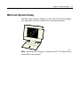
[Auto] Chapter 4:
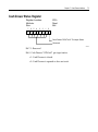
Operating System Recovery
Introduction
This chapter discusses procedures on how to recover the Operating System by using the CD‐ROM drive. The software is distributed on bootable CD‐ROM media. In the event your terminal does not have an internal CD‐ROM drive, the 7446 supports the following external CD‐ROM drive. •
Teac USB CD‐ROM Drive (2336‐K208) It is also possible to perform a BIOS update using a network connection. Refer to the NCR FitClient Software Userʹs Guide, (B005‐0000‐1235) for information about that procedure. Caution: When performing an OS recovery from a larger source image (larger disk) to a smaller destination disk, you must use a special procedure (see the OS Recovery from a Larger Disk Image section). Prerequisites
The following are required in order to perform an OS recovery from a CD. •
Bootable CD‐ROM drive (internal or external) •
Keyboard 4-2
Chapter 4: Operating System Recovery
OS Recovery
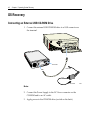
Connecting an External USB CD-ROM Drive
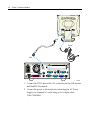
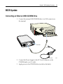
1. Connect the external USB CD‐ROM drive to a USB connector on the terminal. USB
DC Power
DC Power
USB
AC Power
Note: 2. Connect the Power Supply to the DC Power connector on the CD‐ROM and to an AC outlet. 3. Apply power to the CD‐ROM drive (switch on the back). 21689
Chapter 4: Operating System Recovery
4-3
Recovery Procedures
1. Apply power to the terminal. 2. Press [DEL] during boot to enter Setup. 3. At the Setup Utility menu, select Advanced BIOS Features. 4. Set the First Boot Device. •
If you are using the internal CD‐ROM drive, select CDROM. •
If you are using an external USB CD‐ROM drive, select USB-CDROM. 5. Press [Esc] to return to the Setup Utility menu. 6. Select Save and Exit Setup. 7. As the system reboots, insert the NCR Partition Image Application CD (D370‐0605‐0100). You should see a message during boot, indicating that the CD‐ROM has been recognized. 8. At the menu, enter 1 to select the image restore function. ####################################
NCR Partition Image Application
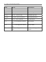
####################################
Select an option
1 – Restore an Image from CD
2 – Exit to a shell with no network connection
3 - Exit to a shell and make a network connection
9. At the prompt, insert the CD which contains the operating system image. Press [Enter]. Windows XPe
D370‐0619‐0100 DOS
D370‐0623‐0100 4-4
Chapter 4: Operating System Recovery
10. At the prompt to continue, press 1 (Yes) and[Enter] to continue. 11. Press [Enter] to mount the CDROM, or [*] to cancel. +------+ Automatic mount +------+
|
|
| Please press “ok” to mount
|
| [/dev/cdrom] on [mnt/cdrom]
|
|
|
|
|
|
+----+
|
|
| Ok |
|
|
+----+
|
|
|
+-------------------------------+
12. Remove the CD from the drive. Completing the OS Installation
Windows XP Pro/Windows XPe
The system automatically reboots when the image recovery is complete and opens at the Welcome screen. DOS
The system automatically reboots when the image recovery is complete and opens at the DOS C:\ prompt. Chapter 4: Operating System Recovery
Gold Disk Contents
This section describes the contents of each of the Gold Disk Images, including all the additions and changes that were installed on top of the generic operating system. NCR 7446-xxxx (WinXP Pro) OS Recovery Software
(LPIN: D370-0635-0100)
Installed Software:
•
Microsoft Windows XP PRO w/ SP1 •
Microsoft Internet Explorer 6.0 SP1 (6.0.2800.1106 SP1) •
Microsoft XP PRO Hotfixes (QFEʹs) •
Video ‐ Intel Graphic Driver (6.13.01.3196) (i815VGA) •
LAN ‐ RealTek RTL8139/810x Family Fast Ethernet NIC 5.612.413.2004 •
Intel Chip Set Utility (5.01.1015) •
Audio ‐ Intel(r)8280/BA/BAM ACʹ97 AC97_Codec‐ADI Software Drivers
The following drivers are not installed automatically, but can be installed from their respective locations (Readme files exist in these locations, as well): •
3M TouchWare •
Hampshire TSHARC USB Touch Drivers available (6.07) version 5.64 SR3 C:\Install\Drivers\Touch\disk1\Setup.exe
C:\Install\Drivers\Hampshire_USB_touch
4-5
4-6
Chapter 4: Operating System Recovery
Special Settings
Furthermore, the following settings/revisions are configured: •
Preinstalled XP Pro to include the Product ID Number (PID) •
Placed the Gold Drive Part Number, Date Created, LPIN, and Release in Registry under: HKey-Local_Machine\Software\NCR\Gold Drive
•
Established a NTFS primary system partition that fills the entire drive •
Set virtual memory to 384
•
Added NCR‐specific EULA Note: This product should only be used on NCR RealPOS 80/80c terminals with a Microsoft Windows XPe license. Recommendation
For each operating system, NCR strongly recommends that any drivers placed in the C:\Install directory be left intact for the purposes of servicing and maintaining the system. If you are using this information in order to build your own operating system image and not using NCR’s provided OS Recovery image as a base image, we recommend that all drivers that are installed be placed in a similar C:\Install directory for support. NCR 7446-xxxx (WinXPe) OS Recovery Software
(LPIN: D370-0619-0100)
Installed Software:
•
Microsoft Windows XPe w/ SP1 •
Intel Extreme Video (6.14.10.3606) •
Intel Pro/100 LAN (7.0.26.0) •
Intel Chip Set Utility (5.01.1015) •
MicroTouch drivers available (5.64 SR1) •
Hampshire TSHARC USB Touch Drivers available (6.07) •
Edgeport USB drivers (2.30) Software Drivers
The following drivers are not installed automatically, but can be installed from their respective locations (Readme files exist in these locations, as well): •
3M‐TouchWare •
Hampshire USB Touch C:\Install\Drivers\Hampshire_USB_touch C:\Install\Drivers\Touch Special Settings
Furthermore, the following settings/revisions are configured: •
Preinstalled XPe to include the Product ID Number (PID) •
Placed the Gold Drive Part Number, Date Created, LPIN, and Release in Registry under: •
Established a NTFS primary system partition that fills the entire drive •
Set virtual memory to 384 •
Added NCR‐specific EULA HKey-Local_Machine\Software\NCR\Gold Drive
4-2
Chapter 4: Operating System Recovery
Note: This product should only be used on NCR RealPOS 80/80c terminals with a Microsoft Windows XPe license. OS Customization
Windows XPe, as built by NCR, has a much larger memory footprint than previous Microsoft operating systems. In order to accommodate the wide a variety customer requirements, more functionality and services are built into the OS than are available in Windows NT, Windows 2000, or Windows XP Pro. If memory footprint or system performance appears sluggish there are a number of ways to reduce memory requirements and increase performance. There are a number of services that may not be required by a customer. Some or all of the services listed below may be modified depending on customer requirements. The first column is the service name and the second column is the suggested startup setting. 6to4
Client Services for Netware
Computer Browser
Cryptographic
Device Update Agent
Dist. Transaction Coord.
DNS Client
Fax
FTP Publishing
HID
Help and Support
IMAPI CD-Burning COM Service
Infrared Monitor
ISS Admin.
IPSEC
Message Queuing
Message Queuing Triggers
Messenger
Network Location Awareness
Portable Media Serial Number
Print Spooler
Protected Storage
Remote Registry
(Disable)
(Disable)
(Manual)
(Disable)
(Manual)
(Manual)
(Manual)
(Disable)
(Manual)
(Manual)
(Manual)
(Disable)
(Disable)
(Disable)
(Disable)
(Disable)
(Disable)
(Disable)
(Disable)
(Disable)
(Manual)
(Disable)
(Disable)
Chapter 4: Operating System Recovery
Secondary Logon Service
Shell Hardware Detection
Simple Mail Transfer
SmartCard
SNMP
SSDP Discovery Service
System Restore
TaskScheduler
TCP/IP Netbios Help
Telephony
Terminal Services
Themes
Upload Manager
Web Client
Windows Time
Wireless Zero Configuration
World Wide Publishing
4-3
(Manual)
(Disable)
(Disable)
(Disable)
(Disable)
(Disable)
(Disable)
(Manual)
(Manual)
(Disable)
(Disable)
(Disable)
(Disable)
(Disable)
(Disable)
(Disable)
(Disable)
In addition, performance may be increased by changing the System Properties Performance settings from letting ʺWindows choose whatʹs best for my computerʺ to ʺAdjust for best performanceʺ and possibly increased by lowering the display resolution. The NCR RealPOS Windows XPe Operating System Recovery Software provides the means of restoring the operating system to the terminal hard disk of a NCR RealPOS 7457 terminal. The bootstrap program (di_natl.bsd) and disk recovery boot image (di_natl.bid) are downloaded to the target terminal over the network and restores the hard disk to the preinstalled state as shipped from the factory. Recommendation
For each operating system, NCR strongly recommends that any drivers placed in the C:\Install directory be left intact for the purposes of servicing and maintaining the system. If you are using this information in order to build your own operating system image and not using NCR’s provided OS Recovery image as a base image, we recommend that all drivers that are installed be placed in a similar C:\Install directory for support. 4-4
Chapter 4: Operating System Recovery
Chapter 5:
BIOS Updating Procedures
Introduction
This chapter discusses procedures on how to update the terminal BIOS by using the CD‐ROM drive. The software is distributed on bootable CD‐ROM media. In the event your terminal does not have an internal CD‐ROM drive, the 7446 supports the following external CD‐ROM drive. •
Teac USB CD‐ROM Drive (2336‐K208) It is also possible to perform a BIOS update using a network connection. Refer to the NCR FitClient Software Userʹs Guide (B005‐0000‐1235) for information about that procedure. Prerequisites
The following are required to perform a BIOS update using a CD. •
Bootable USB CD‐ROM drive •
Keyboard •
Download the BIOS Software from the NCR website. http://www.ncr.com
a. At this site, select Support. b. Under Related Items, Services; select Drivers and Patches. c. Select Retail Support Files. d. Select Retail Platform Software. e. Under Terminals, select 7446. f.
Select your terminal model. 5-2
Chapter 5: BIOS Updating Procedures
g. Select your OS. h. Select the BIOS *.exe file i.
Save the software to your hard drive. Creating the Bootable Media
After downloading the BIOS software you need to create either a bootable Flex diskette or CD. Creating a Bootable Flex Diskette
1. Insert a flex diskette in the PC that has the BIOS software present. 2. Execute the BIOS software (7446_nn.exe). This is a self‐extracting file that will extract the files to the current directory. 3. Execute the Runme.bat file. 4. At the DOS window prompt hit any key to continue. The program then creates the bootable flex diskette containing the BIOS update software. Creating a Bootable CD
Use the bootable flex diskette created above and follow your CD‐RW drive manufacturer’s procedures for creating a bootable CD. Chapter 5: BIOS Updating Procedures
5-3
BIOS Update
Connecting an External USB CD-ROM Drive
1. Connect the external USB CD‐ROM drive to a USB connector on the terminal. USB
DC Power
DC Power
USB
AC Power
2. Connect the Power Supply to the DC Power connector on the CD‐ROM and to an AC outlet. 3. Apply power to the CD‐ROM drive (switch on the back). 21689
5-4
Chapter 5: BIOS Updating Procedures
Updating Procedures
1. Apply power to the terminal. 2. Press [DEL] during boot to enter Setup. 3. At the Setup Utility menu, select Advanced BIOS Features. 4. Set the First Boot Device. •
If you are using the flex diskette drive, select Floppy. •
If you are using the internal CD‐ROM drive, select CDROM. •
If you are using an external USB CD‐ROM drive, select USB-CDROM. 5. Press [Esc] to return to the Setup Utility menu. 6. Select Save and Exit Setup. 7. Insert the media containing the BIOS update software. 8. Follow the screen prompts on the client to update the BIOS. You can select two methods to run the update program. •
Automatic BIOS Update – update process runs unattended Note: You will see a prompt for terminal model and serial number information if the program detects invalid information in the current BIOS, or if you are replacing the processor board, in which case there is not model/serial number information in the BIOS. Important: Model/Serial Number is mandatory. •
Interactive BIOS Update – permits you to input/replace the model/serial number information that is stored in the BIOS. Note: Model/Serial number data that is currently stored in the BIOS is displayed during power up. 9. You should see a green window, indicating a successful update. 10. Remove the media before the system reboots. Chapter 6:
2x20 Customer Display (7446-K451)
Features
•
Data is displayed on two 20‐column lines. •
Large blue–green characters •
The DIP switch settings emulate the command mode, baud rate, and which international character set. •
Command emulation modes include RealPOS 20 and Epson ESC/POS. •
The display area can be controlled by Windows. •
RS‐232 Interface; baud rate from 4800 to 38400 bps. •
Reverse characters can be specified using the Epson command set. 6-2
Chapter 6: 2x20 Customer Display (7446-K451)
General Specifications
ITEM
Descriptions
Display method Vacuum fluorescent display Number of character 40 characters ( 20 columns x 2 lines) Character font 5 x 7 Dot matrix Display color Blue green Brightness 700 cd /㎡ Character type 96 alphanumeric 13 kinds of international character set Character size 9.0mm x 5.25mm Power supply 12 Vdc Power consumption 3 ‐ 6 W Panel dimensions 224 (W) x 93 (H) x 50(D) mm Support dimensions Long support : 22 cm Short support : 9 cm Base dimensions 190(w)x55(h)x96(d)mm Viewing angle ‐5 ‐ 60 degrees Rotation angle Maximum 270 degrees Weight 1.25 Kg Operating temperature 5 ‐ 45℃ Operating Humidity 30%‐85% Storage Temperature ‐10 ‐ 55℃ Storage Humidity 10%‐85% Chapter 6: 2x20 Customer Display (7446-K451)
Interface
Specifications
Data transmission:
Serial Synchronization:
Asynchronous Handshaking:
DTR / DSR MARK = ‐3 to –15 V (logic “1”) Signal level:
SPACE = +3 to +15 V (logic “0”) Baud rates:
4800,9600 *,19200,38400 bps Parity:
None *, even Bit length:
8 bits Stop bits:
1 or more * Default setting 6-3
6-4
Chapter 6: 2x20 Customer Display (7446-K451)
Connector Pinouts
5
RS232C Link to PC/HOST Connector
CN2 / Connector type: D‐sub 9 pin female 6
1
1
Pin Assignment
9
6
No
Signal
Direction
Function description
2 RXD From PC/Host to display Receive data 3 4 5 GND ‐ Signal ground 6 DSR From display to PC/Host Display ready signal 8 DSR From display to PC/Host Display ready signal Display Panel Connector
CN3 / Connector type: Phone‐jack 10P/8C 10
1
Pin assignment
No
Signal
Direction
Function description
‐ Power 12 Vdc 4,5 GND ‐ Signal ground 6 7 DTR From Display to PC/Host Display ready signal 8 9 TXD From Display to Printer Printer status data signal 2,3 Vin Chapter 6: 2x20 Customer Display (7446-K451)
Dip Switch and Software Setting
Command Type Selection
SW1
SW2
SW3
Command type
Default
ON ON ON NCR RealPOS 20 OFF ON ON ESC/POS SW8
SW9
Baud rate (bps)
ON ON 4800 OFF ON 9600 * ON OFF 19200 OFF OFF 38400 * Baud Rate Selection
Default
Parity Check Selection
SW10
Parity check
Default
ON None‐parity * OFF Even‐parity SW11
Show demo string
Default
ON Enable OFF Disable * Demo Mode Selection
6-5
6-6
Chapter 6: 2x20 Customer Display (7446-K451)
International Character Set
SW4
SW5
SW6
SW7
Character set
Code table ( 80H-FFH)
Default
ON ON ON ON U.S.A. PC‐437(USA, standard Europe) OFF ON ON ON FRANCE PC‐858 (multilingual + Euro Symbol) ON OFF ON ON GERMANY PC‐858 (multilingual + Euro Symbol) OFF OFF ON ON U.K. PC‐858 (multilingual + Euro Symbol) ON ON OFF ON DENMARK I PC‐858 (multilingual + Euro Symbol) OFF ON OFF ON SWEDEN PC‐858 (multilingual + Euro Symbol) ON OFF OFF ON ITALY PC‐858 (multilingual + Euro Symbol) OFF OFF OFF ON SPAIN PC‐858 (multilingual + Euro Symbol) ON ON ON OFF JAPAN Katakana OFF ON ON OFF NORWAY PC‐858 (multilingual + Euro Symbol) ON OFF ON OFF DENMARK II PC‐858 (multilingual + Euro Symbol) OFF OFF ON OFF SLAVONIC PC‐852 ON ON OFF OFF RUSSIA PC‐866 OFF ON OFF OFF PORTUGUESE PC860 * Chapter 6: 2x20 Customer Display (7446-K451)
SW4
SW5
SW6
SW7
Character set
Code table ( 80H-FFH)
6-7
Default
ON OFF OFF OFF Not used OFF OFF OFF OFF Not used Command Control
SW12
Function
ON Depends on how SW1~SW11 are set. * Bypasses SW1~SW11 settings and uses the NCR RealPOS 20 settings. Baud rate: 9600 OFF Parity: None Demo Mode: Disabled Character set: USA, Standard Europe Default
6-8
Chapter 6: 2x20 Customer Display (7446-K451)
Command List Table
Table –1
NCR
RealPOS 20
EPSON
ESC/POS
Move cursor right O O Move cursor left O O Move cursor up O O Move cursor down O O Move cursor to right‐most position O O Move cursor to left‐most position O O Move cursor to home position O O O Move cursor to specified position O O Clear display screen O O Clear cursor line O O O Blink display screen O O Initialize display O O Select character code table O Select international character set O Select/cancel reverse character O Overwrite mode O O Vertical scroll mode O O Horizontal scroll mode O O Move cursor to bottom position Brightness adjustment Chapter 6: 2x20 Customer Display (7446-K451)
NCR
RealPOS 20
EPSON
ESC/POS
Set/cancel the window range O Select peripheral device O Set starting/ending position of macro definition
O Execute and quit macro O Execute self‐test O Display time O Display time continuously O Display position O O Change to UTC enhanced mode Change to UTC standard mode Write string to upper line O Write string to lower line O Upper line message scroll continuously O O Message vertical down scroll continuously O Message vertical upper scroll continuously O Carriage return O Line feed O Back space O Horizontal tab O O Cursor on/off Bottom line message scroll continuously Command type select 6-9
6-10
Chapter 6: 2x20 Customer Display (7446-K451)
Table-2
NCR
EPSON
REALPOS 20 ESC/POS
Upper line message scroll once pass Change attention code Two line display Clear upper line and move cursor to upper left‐end position Clear bottom line and move cursor to bottom left‐end position Set period to upper line, last n position Set line blinking, upper line O Clear line blinking, upper line O Clear field 1 and move cursor to field 1, first position Clear field 2 and move cursor to field 2,first position Clear display range from n position to m position and move cursor to n position Save the current displaying data to n layer for
demo display Turn enunciator on/off O Specify period O Specify comma O Specify semicolon (period + comma) O Chapter 6: 2x20 Customer Display (7446-K451)
6-11
Commands
RealPOS 20 Standard Mode Command List
Command
Code (hex)
Function Description
ESC F A .. CR 1B 46 41 [DATA X 40] 0D Write string to upper line ESC F B .. CR 1B 46 42 [DATA X 40] 0D Write string to lower line ESC F D .. CR 1B 46 44 [DATA X 40] 0D Upper line message scroll continuously ESC F O .. CR 1B 46 4F [DATA X 40] 0D Bottom line message scroll continuously ESC P x y 1B 50 x y 1≦x≦20,y=1,2 Move cursor to specified position ESC _ n 1B 5F n n=00,01 Set cursor on/off ESC DC1 1B 11 Overwrite mode ESC DC2 1B 12 Vertical scroll mode ESC DC3 1B 13 Horizontal scroll mode ESC @ 1B 40 Initialize display US MD2 n 1F 02 n n=01~0Ch Message vertical down scroll continuously US MD1 n 1F 01 n n=01~0Ch Message vertical upper scroll continuously US DC1 n 1F 11 n n=’1’,’2’ Set line blinking N=’1’ up line , n=’2’ low line US DC2 n 1F 12 n n=’1’,’2’ Clear line blinking N=’1’ up line , n=’2’ low line US E n 1F 45 n n=0~FFh Blink display screen NULL H 0 48 Move cursor up NULL K 0 4B Move cursor left NULL M 0 4D Move cursor right 6-12
Chapter 6: 2x20 Customer Display (7446-K451)
Command
Code (hex)
Function Description
NULL P 0 50 Move cursor down NULL G 0 47 Move cursor to left‐most position NULL O 0 4F Move cursor to right‐most position BS 08 Back space HT 09 Horizontal tab LF 0A Line feed HOM 0B Move cursor to home position CLR 0C Clear display screen CR 0D Carriage return CAN 18 Clear cursor line, clear string mode Chapter 6: 2x20 Customer Display (7446-K451)
6-13
EPSON ESC/POS Command List-1
Command
Code (hex)
Function description
HT 09 Move cursor right. BS 08 Move cursor left. US LF 1F 0A Move cursor up. LF 0A Move cursor down. US CR 1F 0D Move cursor to right–most position. CR 0D Move cursor to left‐most position. HOM 0B Move cursor to home position. US B 1F 42 Move cursor to bottom position. US $ x y 1F 24 x y (x=1~20, y=01,02) Move cursor to specified position. CLR 0C Clear display screen. US X n 1F 58 n (01≦n≦04) Brightness adjustment. US E n 1F 45 n (n=00~ffh) Blink display screen. ESC @ 1B 40 Initialize display. ESC t n 1B 74 n (n=00‐0fh) Select character code table. ESC R n 1B 52 n (n=00‐0fh) Select international character set. US r n 1F 72 n (n=00,01) Select/cancel reverse character. US MD1 1F 01 Specify overwrite mode. US MD2 1F 02 Specify vertical scroll mode. US MD3 1F 03 Specify horizontal scroll mode. 6-14
Chapter 6: 2x20 Customer Display (7446-K451)
Command
Code (hex)
Function description
CAN 18 Clear cursor line ESC # n 1B 23 n (30h≦n≦38h) Command type select US # n m 1F 23 n m, (n=0 or 1,0<m≦20) Turn enunciator on/off US C n 1F 43 n (n=1,31 then on) Set cursor on/off US . n 1F 2E n, n=a displayable character code Specify period US , n 1F 2C n, n=a displayable character code Specify comma US ; n 1F 3B n, n=a displayable character code Specify semicolon (period + comma) Chapter 6: 2x20 Customer Display (7446-K451)
6-15
EPSON ESC/POS Command List-2
Command
Code (hex)
Function description
ESC W n s x1 y1 x2 y2 1 B 57 n s x1 y1 x2 y2 n=1,2,3,4 s=0,1 Specify/cancel the window range. 1<=x1<=x2<=20 1<=y1<=y2<=2 ESC = n 1B 3D n Select peripheral device. n=1,31, select printer n=2,32, select display n=3,33, select printer, display US : 1F 3A Set starting/ending position of macro definition. Ex.: 1F 3A …………. ( macro string ) ..…. 1F 3A US ^ n m 1F 5E n m Execute and quit macro. 00≦ (n, m)≦ff n=Word time It’s an interval of n between the m=show string time two word. It’s an interval of m between the two string. US @ 1F 40 Execute self ‐ test US T h m 1F 54 h m 0<=h<=17h, 0<=m<=3bh Display time US U 1F 55 Display time continuously 6-16
Chapter 6: 2x20 Customer Display (7446-K451)
Set International Font for ESC/POS (Table 7-11)
n
International font set
n
International font set
0 U.S.A 7 SPAIN 1 FRANCE 8 JAPAN 2 GERMANY 9 NORWAY 3 U.K. 10 DENMARK II 4 DENMARK I 11 SLAVONIC 5 SWEDEN 12 RUSSIA 6 ITALY 15 Reserved Select Code for ESC/POS (Table 7-12)
n
International font set (80H~FFH)
0 Page 0, (PC437: U.S.A., standard Europe) 1 Page 1, (Katakana for Japan) 2 Page 2, (PC858: multilingual + Euro symbol) 3 Page 3, (PC860: Portuguese) 4 Not supported 5 Not supported 6 Page 6, (PC852: SLAVONIC) 7 Page 7, (PC866: RUSSIA) Chapter 6: 2x20 Customer Display (7446-K451)
Character Sets
International Character Sets
ASCII Code
Hex 23
24
40
5B
5C
5D
5E
60
7B
Dec 35
36
64
91
92
93
94
96
123 124 125 126
U.S.A # $ @ [ \ ] ^ ` { | } ~ France # $ à ° ç § ^ ` é ù è ¨ Germany # $ § Ä Ö Ü ^ ` ä ö ü β U.K £ $ @ [ ^ ` { | } ~ Denmark I # $ @ Æ Ø Å ^ ` æ ø å ~ Sweden # ¤ É ä ö å ü Italy # $ @ ° \ é ^ ù à ò è ì Spain Pt $ @ ¡ Ñ ¿ ^ ` ¨ ñ } ~ Japan # $ @ [ ¥ ^ ` { | } ~ Norway # ¤ É Æ Ø Å Ü é æ ø å ü Denmark II # $ É Æ Ø Å Ü é æ ø å ü Slavonic # $ @ [ \ ] ^ ` { | } ~ Russia # $ @ [ \ ] ^ ` { | } ~ Country
\ ] Ä Ö Å Ü é ] 7C
7D
7E
6-17
6-18
Chapter 6: 2x20 Customer Display (7446-K451)
USA, Standard Character Sets (20H – 7EH)
00
01
02
03
04
05
06
07
08
09
0A 0B 0C 0D 0E 0F
“ # $ % & ‘ ( ) ς + , 20H
SP ! 30H
0 1 2 3 4 5 6 7 8 9 : ; 40H
@ A B C D E F G H I K L M N O 50H
P Q R S T U V W X Y Z [ 60H
` 70H
p q r s t a b c d e f g h i J j . / < = > ? \ ] k l u v w x y Z { ‐ ^ _ m n o | } ~ SP Page 0 (PC437: USA, Standard Europe) (80H – FFH)
00
01
02
03
04
05
06
07
08
09
0A 0B 0C 0D 0E 0F
80H
Ç ü é â ä à å ç ê ë è ï î ì 90H
É æ Æ ô ö ò û ù ÿ ö Ü ¢ £ ¥ Pt ƒ A0H
á í B0H
░ ▒ ▓ │ ┤ ╡ ╢ ╖ ╕ ╣ ║ ╗ ╝ ╜ ╛ ┐ C0H
└ ┴ ┬ ├ ─ ┼ ╞ ╟ ╚ ╔ ╩ ╦ ╠ ═ ╬ ╧ D0H
╨ ╤ ╥ ╙ ╘ ╒ ╓ ╫ ╪ ┘ └ █ ▀ ▌ ▐ ▄ E0H
α ß Γ π Σ σ μ τ Ф θ Ω δ ∞ ø ∈ ∩ F0H
≡ ± ≥ ≤ ⌠ ⌡ ÷ ≈ ° • ∙ ó ú ñ Ñ a o ¿ ⌐ ¬ ½ ¼ ¡ √ n ² Ä Å « » ■ SP Chapter 6: 2x20 Customer Display (7446-K451)
Page 1 (Katakana) (80H – FFH)
00
01
02
03
04
05
06
07
08
09
0A 0B 0C 0D 0E 0F
80H
α β γ ⊿ ∈ η θ λ μ π ρ σ τ Ф Ω ∑ 90H
f A0H
SP 。 「 」 、 ‧
ڤ § IE IR ∫ ² ‐1 ³ x ½ 1/ √ ± ■ B0H
C0H
D0H
ʺ E0H
↑ ↓ ← → ↲ ↳
F0H
↱
↰
≠ ≒ ║ │ ⊥
” “ « » ∴ ∵ ~ ~ ≣
∘ 〒 Ω ⊕ Θ Page 2 (PC858: Multilingual+ Euro Symbol) (80H – FFH)
00
01
02
03
04
05
06
07
08
09
0A 0B 0C 0D 0E 0F
80H
Ç ü é â ä à å ç ê ë è ï î ì 90H
É æ Æ ô ö ò û ù ÿ ö Ü ø £ Ø × ƒ A0H
á í B0H
░ ▒ ▓ │ ┤ Á Â À © ╣ ║ ╗ ╝ ¢ ¥ ┐ C0H
└ ┴ ┬ ├ ─ ┼ ã Ã ╚ ╔ ╩ ╦ ╠ ═ ╬ ¤ D0H
ð Đ Ê Ë È € Í E0H
ó ß ô ò õ Õ μ þ Þ Ú Û Ù ý Ý ˉ F0H
ˉ ó ú ñ Ñ a o ¿ ® ¬ ½ ¼ ¡ Î ± ‗ ¾ ¶ § ÷ ¸ Ï ˚ Ä Å « » ┘ └ █ ▀ ¦ Ì ¨ ˙ ¹ ³ ² ▄ ´ ■ SP 6-19
6-20
Chapter 6: 2x20 Customer Display (7446-K451)
Page 3 (PC860: Portuguese) (80H – FFH)
00
01
02
03
04
05
06
07
08
09
0A 0B 0C 0D 0E 0F
80H
Ç ü é â ã à Á ç ê Ê è Í Ô ì Ã Â 90H
É À È ô õ ò Ú ù Ì A0H
á í B0H
░ ▒ ▓ │ ┤ ╡ ╢ ╖ ╕ ╣ ║ ╗ ╝ ╜ ╛ ┐ C0H
└ ┴ ┬ ├ ─ ┼ ╞ ╟ ╚ ╔ ╩ ╦ ╠ ═ ╬ ╧ D0H
╨ ╤ ╥ ╙ ╘ ╒ ╓ ╫ ╪ ┘ └ █ ▀ ▌ ▐ ▄ E0H
α β Γ π Σ σ μ τ Ф θ Ω δ ∞ ø ∈ ∩ F0H
≡ ± ≥ ≤ ⌠ ⌡ ÷ ≈ ° • ∙ Õ Ü ¢ £ Ù Pt Ó ó ú ñ Ñ a o ¿ Ò ¬ ½ ¼ ¡ √ n ² « » ■ SP Page 6 (Slavonic) (80H – FFH)
00
01
02
03
04
05
06
07
08
09
0A 0B 0C 0D 0E 0F
80H
Ç ü é â ä ů ć ç Į 90H
é Ĺ í A0H
á í B0H
░ ▒ ▓ │ ┤ á â ĕ ş C0H
D0H
╨ ╤ ã ë ã ň í E0H
ó β ô ń ń ň š š ŕ ú ŕ F0H
– ̃ ô ö Ľ ĭ ë õ õ î ś ś Ö Ü Ŧ ŧ ó ú ą ą ž ž ę ę ֽ ˇ ˘ § ÷ د į х č ź č ş « » ż ż ═ ě █ ▄ ț ─ ┼ ă ă î ź ä ć ˚ ¨ ˙ ů ▀ ũ ý ý ț ũ ř ř ¤ ́ ■ SP Chapter 6: 2x20 Customer Display (7446-K451)
Page 7 (Russia) (80H – FFH)
00
01
02
03
04
05
06
07
08
09
0A 0B 0C 0D 0E 0F
80H
А Б В Г Д Е Ж З Й Й К Л М Н О П 90H
Р С Т У Ф Х Ц Ч Ш Щ Ъ Ы Ь Эį Ю Я A0H
а б в г д е ж з и й к л м н о п B0H
C0H
D0H
E0H
р с т у ф х ц ч ш щ ъ ы ь э ю ́я F0H
∂ Ґ K H θ Y Y h ∂ ґ k h θ Y Y SP 6-21
6-22
Chapter 6: 2x20 Customer Display (7446-K451)
Command details
Overwrite Mode
In this mode, the cursor moves from left to right, beginning at the upper left position. When the cursor reaches the end of the upper line, it then moves to the beginning (left end) of the bottom line. When the cursor reaches the end of the bottom line, it then moves back to beginning of the upper line and overwrites the previous characters. Vertical Scroll Mode
In this mode, the cursor moves from left to right, beginning at the upper left position. When the cursor reaches the end of the upper line, it then moves to the beginning (left end) of the bottom line. Horizontal Scroll Mode
In this mode, the horizontal movement of the cursor is limited to a predefined range and is limited to the upper line. (See the Set or Cancel Window command to set the default window as the entire upper line.) The cursor moves from left to right, beginning at the left end of the range, and moves to the right until it reaches the end of the range. Additional characters then push the existing characters to the left, scrolling the characters to the left. Chapter 6: 2x20 Customer Display (7446-K451)
6-23
Set the String Display Mode, and Write String to Display
To set the String Display Mode, write to the upper or lower line. d1 d2 d3 ….. dn {1≦n≦20} A = upper line B = lower line The String Display Mode is cancelled and returns to the last mode after receiving the CLR or CAN command. Upper Line Message Scroll Continuously
The message (previously defined) scrolls continuously in the horizontal direction until a new command is received. Move Cursor Left
This command moves the cursor to the left. It operates differently when the cursor is at the beginning of the line, depending on which display mode is used. Overwrite Mode: When the cursor reaches the beginning of the lower line, it then moves to the end of the upper line and overwrites the previous character. When it reaches the left end of the upper line, it then moves to the end of the lower line. Vertical Scroll Mode: When the cursor reaches the beginning of the lower line, the lower line then scrolls up and replaces the upper line. The lower line is cleared and the cursor moves to the end of the lower line. Horizontal Scroll Mode: The cursor remains stationary. 6-24
Chapter 6: 2x20 Customer Display (7446-K451)
Move Cursor Right
This command moves the cursor to the right. It operates differently when the cursor is at the end of the line, depending on which display mode is used. Overwrite Mode: When the cursor reaches the end of the lower line, it then moves to the beginning of the upper line and overwrites the previous character. When it reaches the end of the upper line, it then moves to the beginning of the lower line and overwrites. Vertical Scroll Mode: When the cursor reaches the end of the lower line, the lower line scrolls up to replace the upper line. The lower line is cleared and ready for new characters. Horizontal Scroll Mode: The cursor remains stationary. Move Cursor Up
This command moves the cursor up one line. It operates differently when the cursor is on the upper line, depending on which display mode is used. Overwrite Mode: The cursor moves to the same column in the lower line. Vertical Scroll Mode: The characters displayed on the upper line are scrolled to the lower line and the upper line is cleared. The cursor remains in the same position. Horizontal Scroll Mode: The cursor remains stationary. Chapter 6: 2x20 Customer Display (7446-K451)
6-25
Move cursor down
This command moves the cursor down one line. It operates differently when the cursor is on the lower line, depending on which display mode is used. Overwrite Mode: The cursor moves to the same column in the upper line. Vertical Scroll Mode: The characters displayed on the lower line are scrolled to the upper line and the lower line is cleared. The cursor remains in the same position. Horizontal Scroll Mode: The cursor remains stationary. Vertical scroll
The characters displayed on the lower line are scrolled to the upper line and the lower line is cleared. The cursor remains in the same position. Horizontal scroll mode: The cursor remains stationary. Move Cursor to Home Position
The cursor moves to the beginning of the upper line Move Cursor to Left-Most Position
The cursor moves to the beginning of the current line. Move Cursor to Right-Most Position
The cursor moves to the end of the current line. Move Cursor to Bottom Position
The cursor moves to the end of the lower line. 6-26
Chapter 6: 2x20 Customer Display (7446-K451)
Move Cursor to Specified Position
The cursor moves to the x column on the y line. Initialize Display
The data in the input buffer is cleared and reset to the default value. Reset the Window
Resets the window on the display. When s=0, the window is cancelled (values: x1, x2, and y are not required.) When s=1 the window is reset (values: x1, x2, and y are required.) x1 and x2 set the position of the left column and right column, respectively, of the window. y sets the upper or lower line of the window. This function is valid only in the Horizontal Mode. Clear Display Screen, and Clear String Mode
The displayed characters are cleared and the String Mode is cancelled. Clear current line, and cancel string mode
The current line is cleared and the string mode is cancelled. Brightness adjustment
Adjusts the brightness of the vacuum fluorescent display. When n=3, brightness=70% When n=4, brightness=100% Set cursor ON or OFF
When n=0, cursor is OFF When n=1, cursor is ON Chapter 6: 2x20 Customer Display (7446-K451)
Control Code Set
HEX
CODE
HEX
CODE
00H NULL 10H DLE 01H SOH, MD1 11H DC1 02H STX, MD2 12H DC2 03H ETX, MD3 13H DC3 04H EOT, MD4 14H DC4 05H ENQ, MD5 15H NAK 06H ACK, MD6 16H SYN 07H BEL, MD7 17H ETB 08H BS, MD8 18H CAN 09H HT 19H EM 0AH LF 1AH SUB 0BH VT, HOM 1BH ESC 0CH FF, CLR 1CH FS 0DH CR 1DH GS 0EH SO, SLE1 1EH RS, SF1 0FH SI, SLE2 1FH US, SF2 6-27
6-28
Chapter 6: 2x20 Customer Display (7446-K451)
Code Example
#include
#include
#include
#include
#include
#include
<dos.h>
<stdio.h>
<graphics.h>
<bios.h>
<conio.h>
<malloc.h>
#define CR
#define ESC
13
27
union
REGS regs ;
char title[] ="\n\n
VFD Testing Program " ;
char line1[] ="\n
Comport Select 1:Com1 2:Com2 3:Com3 4:Com4
6:Com6 Esc:Quit :" ;
char line2[] ="Test Prog 8/ 1/2000\n" ;
char low_line[] ="Send string to line2\n" ;
char fix_p[] ="0K2000,+25000\n" ;
char string[]="DemoProgramm";
char string2[]="Welcome !!2003/06/29";
unsigned ComPort,count,ComSelect;
unsigned Status,j,k,c,d,ch,chold;
void main()
{
unsigned
data ;
char
*ComData;
int
tempLoop;
unsigned char charcount1,charcount2;
ProgramStart:
clrscr();
printf(title);
printf(line1);
ComPort_Select:
ComSelect=getch();
switch(ComSelect){
case('1'): ComPort=0;ComData="Now = COM1,9600,N,8,1
case('2'): ComPort=1;ComData="Now = COM2,9600,N,8,1
case('3'): ComPort=2;ComData="Now = COM3,9600,N,8,1
case('4'): ComPort=3;ComData="Now = COM4,9600,N,8,1
case('6'): ComPort=5;ComData="Now = COM6,9600,N,8,1
break;
case(ESC): goto programmend;break;
"; break;
"; break;
"; break;
"; break;
";
Chapter 6: 2x20 Customer Display (7446-K451)
default: printf("\n
Error!!");cur_homeB();goto
ComPort_Select;break;
}
charcount1=0;
charcount2=0;
ch=1;
data = _COM_CHR8 | _COM_STOP1 | _COM_NOPARITY | _COM_9600 ;
_bios_serialcom(_COM_INIT, ComPort , data) ;
cur_homeA();
printf("\n
Press any key to show (F10 to quit) ") ;
printf(ComData);
printf("\n
\n");
/*_bios_serialcom(_COM_SEND,ComPort,0x1b);
_bios_serialcom(_COM_SEND,ComPort,0x47);
for(tempLoop=0;tempLoop<1920;tempLoop++)
{
_bios_serialcom(_COM_SEND,ComPort,0x58);
}*/
do
{
if(kbhit()) //check if hit any key
{
c=getch();
if (c==68 && d==0)
goto programmend;
printf("\n
Input Data ====
%d ====
%c",c,c);
_bios_serialcom(_COM_SEND,ComPort,c);
}
/*if(charcount1<20)
{ _bios_serialcom(_COM_SEND,ComPort,string[charcount1]);
printf("\n%c--%i--",;
charcount1++;
}
else
{
if(charcount2<20)
{ _bios_serialcom(_COM_SEND,ComPort,string2[charcount2]);
charcount2++;}
else
{ charcount1=0;
charcount2=0;}
}
delay(500);*/
//d=c;
6-29
6-30
Chapter 6: 2x20 Customer Display (7446-K451)
//ch++;
//if (ch>15)
// { cur_home();
//
for (chold=1;chold<16;chold++)
//
delline();
//
ch=1; }
}
while(1);
programmend:
}
cur_home()
{
regs.h.ah =
regs.h.bh =
regs.h.dh =
regs.h.dl =
int86(0x10,
return 0;
}
cur_homeA()
{
regs.h.ah =
regs.h.bh =
regs.h.dh =
regs.h.dl =
int86(0x10,
return 0;
}
cur_homeB()
{
regs.h.ah =
regs.h.bh =
regs.h.dh =
regs.h.dl =
int86(0x10,
return 0;
}
2;
0;
5;
0;
®s, ®s) ;
2;
0;
2;
0;
®s, ®s) ;
2;
0;
3;
66;
®s, ®s) ;
Chapter 7:
Cash Drawer Interface
Software Drivers
Peripheral drivers can be downloaded from the NCR website (http://www.ncr.com)
1. At this site, select Support. 2. Under Related Items, Services; select Drivers and Patches. 3. Select Retail Support Files. 4. Select Retail Platform Software. 5. Select Terminals → 7446 → [Model] → [Platform] → [OS]. 6. At this screen download the OPOS_Cash_Drawer.ZIP file. Install the software on the 7446 as a PC. Cash Drawer Pin Assignment
Pin
Signal
1 GND 2 DOUT bit0 3 DIN bit0 4 12V/24V 5 DOUT bit1 6 GND 7-2
Chapter 7: Cash Drawer Interface
Cash Drawer Controller register description
The Cash Drawer Controller uses two I/O addresses to control the Cash Drawer. •
Cash Drawer Control Register •
Cash Drawer Status Register. Cash Drawer Control Register
Register Location:
Attribute:
Size:
200h
Write
8bit
7
6
5
4
3
2
X
X
X
X
X
X
1
0
Cash Drawer "DOUT bit 0" Pin Output Control
Cash Drawer "DOUT bit 1" Pin Output Control
Reserved
21924
Bit 7‐2: Reserved Bit 1: Cash Drawer “DOUT bit1” pin output control. = 1: Open the Cash Drawer = 0: Allow closing the Cash Drawer Bit 0: Cash Drawer “DOUT bit0” pin output control. = 1: Open the Cash Drawer = 0: Allow closing the Cash Drawer Note: Please follow the Cash Drawer control signal design to control the Cash Drawer. It is recommended that you control bit1/0 at the same time. Chapter 7: Cash Drawer Interface
7-3
Cash Drawer Status Register
Register Location:
Attribute:
Size:
201h
Read
8bit
7
6
5
4
3
2
1
X
X
X
X
X
X
X
0
Cash Drawer "DOUT bit 0" Pin Intput Status
Reserved
21925
Bit 7‐1: Reserved Bit 0: Cash Drawer “DIN bit0” pin input status. = 1: Cash Drawer is closed. = 0: Cash Drawer is opened or does not exist. 7-4
Chapter 7: Cash Drawer Interface
Cash Drawer control command example
Use the Debug.EXE program under DOS or Windows98. Command
Cash Drawer
O 200 01 To Open O 200 00 Allow to close •
Set the I/O address 200h bit0 =1 to open the Cash Drawer by “DOUT bit0” pin control. •
Set the I/O address 200h bit0 = 0 to allow you to close the Cash Drawer. Command
Cash Drawer
I 201 Check status •
The I/O address 201h bit0 =1 indicates the Cash Drawer is opened or not exist. •
The I/O address 201h bit0 =0 indicates the Cash Drawer is closed. Chapter 7: Cash Drawer Interface
Code Example
#include<dos.h>
#include<conio.h>
#define
DigitalPort
0x200
char title[] =
"
First Cash Box Testing Program \n" ;
char line[] =
"
========================================== \n" ;
void main()
{
int PortStatus;
while(1)
{
if((inportb(DigitalPort+1)&0x01)==0)
{
printf("\n\n\n\n\n");
printf("\t\t\tCash box is OPEN status.");
printf("\n\n");
printf("\t\t\tPlease close cash box.");
while((inportb(DigitalPort+1)&0x01)==0)
;
}
clrscr();
//clear screen
printf("\n\n\n\n");
printf(line);
printf(title);
printf(line);
printf("\n\n\n\n\n\n\n\n");
printf("\tPress any key to open the cash box (ESC to
quit)");
if(getch()==27)
break;
clrscr();
7-5
7-6
Chapter 7: Cash Drawer Interface
do
{
outportb(DigitalPort,0x01);
delay(300);
outportb(DigitalPort,0x00);
//Control Pin=1
// Delay Time
//Control Pin=0
PortStatus=inportb(DigitalPort+1);
PortStatus=PortStatus&0x01;
//Read Cash Box Status
if(PortStatus==1)
delay(2000);
}
while(PortStatus==1);
}
}
Appendix A: Cables
Appendix A:
A-1
Cables
Printer Cables
Printer Power Cable (24V)
497-0435073 - 2m
1416-C984-0020
Power
(Printer)
24V
(Terminal)
21638a
RS-232 (9-Pin to 9-Pin)
497-0408349 - 0.7 m
(1416-C359-0007)
9-pin
D-shell
Receptacle
RS-232
(Printer)
497-0407943 - 4 m
(1416-C266-0040)
9-pin
D-shell
Receptacle
RS-232
(Terminal)
19722a
A-2
Appendix A: Cables
RS-232 (9-Pin to 25-Pin)
497-0407427 - 1.0 m
(1416-C337-0010)
9-pin
D-shell
Receptacle
497-0407429 - 4 m
(1416-C337-0040)
RS-232
(Terminal)
25-pin
D-shell
Plug
RS-232
(Printer)
20127b Standard USB
497-0415949 - 1m
1416-C528-0010
497-0415950 - 4m
1416-C528-0040
USB
(Printer)
USB
(Terminal)
21639
Appendix A: Cables
A-3
Scanner Cables
7872 or 7875 Scanner/Scale (RS-232)
D-Shell
9-Pin
Receptacle
497-0300422 - 4 m
(1416-C019-0040)
Modular
10-Pin
Plug
RS-232
(Scanner)
RS-232
(Terminal)
15479a
7892 Scanner (Powered RS-232)
D-Shell
9-Pin
Receptacle
497-0425593 - 3.0 m
(1416-C643-0030)
Modular
10-Pin
Plug
RS-232
(Terminal)
Scanner
20450a
7882 Scanner (Powered RS-232)
D-Shell
9-Pin
Receptacle
RS-232
(Terminal)
497-0419723 - 4.0 m
(1416-C653-0040)
Modular
10-Pin
Plug
Scanner
19728a
A-4
Appendix A: Cables
7837 Scanner (Powered RS-232)
497-0426457 - 2.5 m
(1416-C806-0025)
Powered
RS-232
(7456/7458)
Scanner
D-Shell
9-Pin
Receptacle
Modular
10-Pin
Plug
21206
7837 Scanner (RS-232, External Power)
External
Power
497-0412951 - 2.5 m
(1416-C429-0025)
RS-232
(Terminal)
Scanner
D-Shell
9-Pin
Receptacle
Modular
10-Pin
Plug
21154
Appendix A: Cables
A-5
Display Cables
VGA Display, Mono
Sub Miniature D-Shell
15-Pin
Plug
497-0008164 - 4 m
1416-C042-0040
Sub Miniature D-Shell
15-Pin
Receptacle
VGA
(CRT Display)
VGA
(Terminal)
14607a
VGA Display, Color
1.0 m Black 497-0428080
1416-C840-0010
1.5 m Black 497-0428068
1416-C839-0015
1.0 m White 497-0424530
1416-C753-0015
1.5 m White 497-0424531
1416-C754-0010
Sub Miniature D-Shell
15-Pin Receptacle
Sub Miniature D-Shell
15-Pin Plug
VGA
(Display)
VGA
(Terminal)
16318a
19741a
CRT AC Power Extension
497-0406237 - 4m
(1416-C508-0040)
A-6
Appendix A: Cables
5942 12.1 Inch LCD
Sub Miniature D-Shell
15-Pin
Plug
497-0009680 - 4 m
1416-C261-0040
Sub Miniature D-Shell
15-Pin
Receptacle
VGA
(CRT Display)
VGA
(Terminal)
21637a
5982 5-Inch LCD
Champ
50-pin Plug
497-0409750 - 4m
24-pin
Minifit Plug
LCD
(PCI Card)
5982
19731a
5972 VFD Customer Display (Powered RS-232)
497-0420926 - 1 m
1416-C683-0010
9-pin
D-Shell
Receptacle
Terminal
RS-232 Port
497-0420927 - 4 m
1416-C683-0040
24-Position
Microfit
Receptacle
Customer
Display
20279
Appendix A: Cables
A-7
Ethernet, 10/100BaseT Cable
497-0008905 - 3.0 m
(1416-C059-0030)
Modular
8-Pin
Plug
Modular
8-Pin
Plug
16298a
PS/2 Keyboard Extension Cable
6-pin
Mini-DIN
Plug
497-0406056 - 1.8 m
(1416-C281-0018)
6-pin
Mini-DIN
Receptacle
PS/2
(Terminal)
PS/2
(Keyboard)
15403a
Signature Capture/Electronic Payment Terminal Cable
5945/5992 EPT (RS-232 w/Power)
9-pin
Mini-DIN
Plug
RS-232
(EFT Unit)
497-0418406 - 4.0 m
(1416-C634-0040)
9-pin
D-shell
Receptacle
RS-232
(Terminal)
19723a
A-8
Appendix A: Cables
Power Cables
AC Power
1416-C325-0030 006-1009037 - U.S.
Terminal/CRT
The following power cables (not shown)
also have an IEC connection of 45 mm:
1416-C320-0030 006-8601011 - SEV
1416-C321-0030 006-8601012 - U.K.
1416-C322-0030 006-8601019 - Australia
1416-C323-0030 006-8601010 - International
1416-C391-0030 006-8605488 - China
1416-C393-0030 006-8601001 - Japan Twist-Lock
15405a
497-0436751
1416-C131-0001
Mini-IEC
IEC-320 Shrouded Plug
21926
Appendix B: Memory Maps
This memory map is based on the BIOS Load Optimized Defaults and does not have any add‐on cards. B-2
Appendix B: Memory Maps
With the 2.1.3.3 BIOS the memory used for the DMI strings starts at a different location if the Legacy USB is enabled in the BIOS Setup. With Legacy USB enabled, the DMI strings start at D800:0. If Legacy USB is disabled, then the DMI strings start at DC00:0.