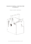
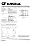
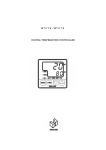
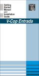
1
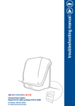
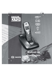
MN07930-00-080306
MEDIUM-SIZED
DC FAN-TYPE
MODEL ENZR-GB
INSTRUCTION MANUAL
- Read this instruction manual and make sure you thoroughly
understand its contents before attempting to operate, inspect or
service this product.
- The users and supervisors of this product must not let anyone to
operate this product if unfamiliar with it.
WE5642
1
MN07930-00-080306
INTRODUCTION
This instruction manual is a guidebook to allow safely and effectively using this product.
Always be sure to read this instruction manual and thoroughly understand its contents before
attempting to operate, inspect or service this product.
Failure to comply with this instruction might lead to serious accidents. Caution items
are listed at various points throughout this instruction manual. These displays are points
where special caution is needed to maintain safety so proceed with the task after making sure
you fully understand the necessary information.
-
Using this product without adequate preparation may lead to serious injuries or
major accidents.
-
The operator and maintenance personnel shall read this manual carefully before
attempting to operate or service this product.
-
Do not operate or service this product until you fully understand the contents of this
service manual.
-
Store this manual near the product so it can be easily referred to when needed. If this
manual is lost or is damaged then promptly order another copy from our company or
dealer.
-
Before granting this product to another party, always makes sure to send this
instruction manual along with it, to the new owner of the product.
-
Please acknowledge beforehand that our company bears absolutely no responsibility
for the operation or results of operation of this product.
WE5642
2
MN07930-00-080306
Contents
Introduction
1.
Safety Information................................................................................................................................... 4
2.
Overview ................................................................................................................................................. 5
3.
4.
Features ................................................................................................................................................... 5
Package Contents .................................................................................................................................... 5
5.
Main Components and Functions............................................................................................................ 6
6.
7.
Installation............................................................................................................................................. 10
Adjusting the ion balance ...................................................................................................................... 14
8.
Maintenance .......................................................................................................................................... 15
9.
10.
Specifications .................................................................................................................................... 19
Troubleshooting................................................................................................................................. 20
11.
External dimensions .......................................................................................................................... 21
WE5642
3
MN07930-00-080306
1. Safety Information
Meaning of displays and messages
The safety displays and messages are organized as follows to make sure you fully understand this
instruction manual and the product safety labels.
△DANGER
!
- This term is used in safety messages and on safety labels in locations where
there is a high possibility that serious injury or even death might occur from
failure to avoid a particular hazard.
- These safety messages include prevention measures that must be implemented
to avoid a particular hazard.
△WARNING
!
- This term is used in safety messages and on safety labels in locations where
there is a high possibility that serious injury or a major accident might occur
from failure to avoid a particular hazard.
- These safety messages include prevention measures that must be
implemented to avoid a particular hazard.
△NOTE
!
- This term is used in safety messages and on safety labels in locations where
there is a high possibility that minor injury or material damage might occur
from failure to avoid a particular hazard.
- These safety messages include prevention measures that must be
implemented to avoid a particular hazard.
WE5642
4
MN07930-00-080306
2. Overview
In this electrostatic eliminator (ionizer), the DC fan and DC high-voltage supply are integrated into a
single structure and connected to a DC power supply.
In manufacturing processes using insulating materials such as semiconductors and molded parts,
electrostatic charges occur due to peeling or machining processes.
These electrostatic charges hurt
productivity because of damage from electrostatic discharge (ESD) or from dust adhering to the material
and therefore require ESD protective measures.
The high-voltage in this unit is extremely hazardous to personnel and equipment so read the
instruction manual carefully and make sure you understand it before using the equipment.
To ensure safety, the ionizer electrodes in this device are resistively coupled so that the high–voltage
supply does not apply voltages directly to the discharge needle. However, be careful not to directly touch
the discharge needle with bare hands.
3. Features
(1)
Unit is simple and safe to install since no high voltage cable wiring are required.
(2) Ions in this device can reach further than in AC ionizers so this ionizer is ideal for use in ionizing
cramped, narrow and remote locations.
(3) Static charges are efficiently removed regardless of the charge polarity or voltage potential
because of the excellent ion polarity balance.
There is virtually no charge inversion due to ion
emission.
(4) Safe design incorporates a current control circuit in the ion emission electrodes so operation is
stable with no voltage surges.
(5) Make fine adjustments to the ion balance by using the BALANCE knob on the front panel.
(6) Adjust the blowing level with the FAN SPEED knob on the front panel.
(7) A cleaning alarm informs the user via a LED on the front panel (red CLEANING lamp lights up)
when cleaning is required. External warnings (outside unit) can be made by connecting the
output from the terminal block to an alarm, etc.
(8) A LED on the front panel lights up if the DC fan is broken. An external warning/alarm can be
output by connecting to outputs on the terminal block.
(9) Power supply can be turned on or off by making connections to the terminal block.
4. Package Contents
1. ENZR-GB
2. Instruction Manual (this text)
3. Dedicated AC adapter (Option、Other selling:ENZR-BAC)
WE5642
5
MN07930-00-080306
5. Main Components and Functions
(4)
(10)
POWER
ENZR-GB
(6)
(1)
(2)
(3)
(5)
(9)
(7)
(8)
(11)
(1) Power switch
(2) Fan failure lamp
(3) Cleaning lamp
(5) Fan speed adjusting knob
(6) Ion balance fine adjusting knob
(8) Power supply connector
(9) Terminal block
(4) Fan guard
(7) PL label
(10) Angle adjusting knob
(11) Mounting hole
(1) Power switch
lights up
Turn on this switch to operate the ionizer (ENZR-GB).
(If operating normally, the switch LED lights up and
the green FAN MONITOR and CLEANING lamps light up.)
Green
lamps light up
(2) Fan failure lamp
The LED indicator on front panel shows if the DC fan is defective.
(During normal operation the green LED for the FAN MONITOR lights up. If
defective, a red LED lights up.)
WE5642
6
MN07930-00-080306
(3) Cleaning lamp
A cleaning alarm informs the user via a LED on the front panel (red CLEANING
lamp lights up) when cleaning is required or there is a breakdown.
Cleaning period:
During normal operation the green CLEANING LED lights up on the front panel.
During the cleaning period (cleaning is required) the LED lights up in red.
During breakdowns:
The power switch LED turns off, and the red CLEANING LED lights up.
Red LED turns off.
Changes from red to green.
Changes from green to red.
ENZR-GB
ENZR-GB
Cleaning period
During breakdowns/defects
(4) Fan guard
A fan guard is installed for stable ionizing and to prevent injuries.
(5) Fan speed adjusting knob
Use to adjust the DC fan speed.
(Fan speed is set to a maximum prior to delivery.)
(6) Ion balance fine adjusting knob
Use to adjust the ion balance as required when the ion balance has deteriorated in the
area where ionizing is required.
(7) PL label
The following labels have been attached to ensure safety.
Read the information on the labels and follow their instructions.
WE5642
7
MN07930-00-080306
注意
! CAUTION
注意
! CAUTION
Do not
感電の恐れ
touch
あり放
電針
discharge
に触れるな
needle!
! 注意
感電の恐れ
あり放電針
に触れるな
Electrical
必ずアース線
shock
hazard!
を接
地せよ
! 注意
必ずアース線
を接地せよ
(8) Power connector for dedicated AC adapter (option、Other selling:ENZR-BAC)
△ DANGER
!
- This product is designed to operate on 24 volts DC. Product
performance cannot be maintained unless the correct voltage is
used and using the wrong voltage might cause fires or
breakdowns, etc.
- Always connect this unit to an electrical ground.
(9) Terminal block
No.
1( )
Name
POWER IN
2 (GND)
3( )
POWER OUT
4 (GND)
5
(Collector)
6
(Emitter)
OPERATION OUT
7
(Collector)
8( )
9 (GND)
BUZZER
GROUND TERMINAL
Remarks
24 volts DC±10%
Connect to power supply if not using power connector (8).
24 volts DC±10%
Use this terminal when connecting ionizers in series. (Up to
5 units can be connected when using a switching power
supply.)
Photo coupler, open collector output, photo coupler
maximum rating 50mA, 55volts (10mA, 24volts
recommended) open at power supply-off, and during the
cleaning alarm.
Terminal No. 5 and terminal No. 6 are for the cleaning alarm.
Terminal No. 7 and terminal No. 6 are for the fan failure
alarm.
Use this when connecting the DC buzzer.
Buzzer sounds during any of the alarms.
Always supply a ground connection. (- DC side) (Use a D
type ground (structures using 300 volts or less.)
* The ground terminal and –DC side shall be connected in common.
WE5642
8
MN07930-00-080306
- This product is designed to operate with DC 24 volts.
Product
performance cannot be maintained unless the correct voltage is
△DANGER
!
supplied and supplying the wrong voltage might cause fires or
breakdowns, etc.
- Connecting a wire to the wrong terminal No. on the block might not
only cause equipment breakdown but may also damage other
equipment. This might also cause fires or accidents to occur.
- Always connect this unit to an electrical ground.
(10) Angle adjusting knob
Use this knob when adjusting the opening angle on the ionizer (ENZR-GB).
See the diagram below for information on using the knob.
Loosen the thumbscrew
Set to the angle you want
Tighten the thumbscrew
(11) Mounting hole
This is a hole for clamping the ionizer (ENZR-GB).
Dedicated AC adapter (Option、Other selling:ENZR-BAC)
△DANGER
!
- This AC adapter is designed to accept AC 100 to 240 volts
at 50/60 Hz. Failure to use the correct voltage will not only lower
product performance but might also cause fires or breakdowns, etc.
- Always connect this unit to an electrical ground.
WE5642
9
MN07930-00-080306
68
A
1.83m±50
26
50
A矢視A
view
1.8m±100
6. Installation
6-1 Installation
△DANGER
!
- During installation, always turn off the power supply of the device
where this product is installed and post a sign showing installation is in
progress. A major accident involving human life might happen if that
device suddenly starts operating while installing this product.
- This product is an electrostatic eliminator (ionizer) and is not produced
△ NOTE
!
to meet explosive proof specifications.
So do not use it in
environments where explosions might occur due to dust or inflammable
solvents, etc.
- To ensure safety, install this ionizer in a location where the operation
lamp can be seen. Also install in a location free from water and oil, etc.
Always turn off the power switch for the DC power supply before
starting this task.
- Always be sure to check that no power is being supplied (AC adapter
has been removed from the socket.)
WE5642
10
MN07930-00-080306
[How To Install]
1. Set the ionizer position, height and tilt, so that ionizing can be properly performed within the range
where needed.
2. Clamp the ionizer (ENZR-GB) securely using the installation holes in the stand.
3. Adjust the ion balance after checking “7. Adjusting the ion balance.”
Cautions during installation
- Make sure there are no obstructions between the ionizer (ENZR-GB) and the work piece for
ionizing.
Obstructions between the ionizer and work piece might badly affect ionizing
performance.
- Make sure the foundation is sufficiently sturdy before clamping the unit.
ALWAYS INSTALL A GROUND FROM THE DEDICATED AC ADAPTER OR THE TERMINAL BLOCK.
(ALWAYS USE A GROUND IN ORDER TO PREVENT ELECTRICAL SHOCKS
AND TO OBTAIN ACCURATE IONIZING.)
6-2 Making connections
!
注意
感電の恐れ
あり放電針
に触れるな
!
注意
必ずアース線
を接地せよ
[Terminal specification]
Maximum rating
Cables/wires
125 volts 4 amps
AWG26 ∼ 20
If using single-core cable wire
Insert about 5mm of stripped (bare) wire into the
clamp section without pressing the open/close lever
on the terminal block.
After inserting, pull gently on
the wire to check that it will not come loose.
If using stranded cable wire
Insert about 5mm of stripped (bare) wire into the
clamp section while pressing the open/close lever on
the terminal block, and then release the lever. After
inserting, pull gently on the wire to check that it will
not come loose.
WE5642
11
MN07930-00-080306
[Removing the terminal block]
The terminal block is somewhat stiff so to remove it more easily, pull on it while tilting to the right and left.
When installing the terminal block, insert while aligning it to face correctly.
TOP VIEW
上面図
Grip with the fingers from both sides and pull.
NOTE: The terminal block might prove somewhat stiff when attempting to remove it so tilting
left and right while pulling will make it easier to remove.
SIDE VIEW
側面図
Grip this side with
the fingers
[Operation output]
⑤
Cleaning alarm – High voltage circuit error alarm
Operating conditions
- 5 and 6 are ON during normal operation
- 5 and 6 are OFF during an error/alarm
⑥
⑦
Fan failure alarm
Operating conditions
- 7 and 6 are ON during normal operation
- 7 and 6 are OFF during an error/alarm
⑥
WE5642
12
MN07930-00-080306
Buzzer output
Operating conditions
⑧
- During normal operation: DC buzzer is OFF
- During alarm/error: DC buzzer is ON
(Buzzer sounds during any alarm.)
⑨
WE5642
13
MN07930-00-080306
7. Adjusting the ion balance
7-1 Always connect a ground line
△NOTE
Always use the charge plate monitor
!
when adjusting the ion balance.
[How to adjust]
1. Mount the charge plate monitor at the front side (location where you want to perform ionizing) of the
ionizer (ENZR-GB).
2. Adjust the ion balance adjusting knob (BALANCE on front panel) while viewing the voltage
displayed on the charge plate monitor so that the ion balance is in the range of 0 volts ± 10 volts.
(NOTE: After turning the ion balance fine adjusting knob, it may take some time before the
ion balance stabilizes so do not turn the adjusting knob immediate after the turning
ENZR-GB power on.
Turn the knob slowly while monitoring the voltage displayed on the
charge plate monitor.)
+
○
+
○
−
○
−
○
+
○
−
○
−
○
+
○
−
○
+
○
−
○
−
○
+
○
+
○
−
○
−
○
+
○
V
SE C
3. Check whether applying the voltage to the charge plate improves the ionizing performance
(according to your company’s specification).
Use after verifying the ionizing performance.
4. If the ion balance cannot be adjusted to 0 volts ± 10 volts even after turning the ion balance fine
WE5642
14
MN07930-00-080306
adjust knob or if ionizing is inadequate, then consult, “8. Maintenance” and take action such as
cleaning the needles, etc.
8. Maintenance
8-1 Periodic inspections
When this device is used for extended periods of time, dust adheres to the sides of the electrode pin.
When this dust adheres to the electrode pin it lowers ionizing performance and causes the ion balance
to deteriorate. Clean these periodically (once every 1 to 2 weeks) even if the cleaning lamp does not
light up (Green during normal operation, and red during alarm).
△DANGER
!
- Before cleaning, always turn off the power switch, and pull out the
AC adapter power cord; or remove the terminal block. Major
accidents due to electrical shock might occur if the power is turned
on during the cleaning task.
△WARNING
!
- Always read the instruction manual before starting the cleaning task.
After cleaning, check that the discharge needles of the ionizer
electrode have completely dried before using. If these are not dry
then a sparking hazard might occur.
- Before using, adjust the ion balance after consulting, “7. Adjusting
the ion balance”.
[Cleaning procedure]
1. Turn off the ionizer power switch and remove the AC adapter power cord (Remove the terminal block
if supplying power by using the terminal block.).
2. Remove the fan guides on the front side and rear side, and clean the electrode pin, fan vanes,
and around the electrode pin with benzene (or equivalent) using a cotton swab. (sold
separately)
WE5642
15
MN07930-00-080306
Clean the electrode pin, vicinity of electrode
pin, and fan.
ENZR-GB
* Let the benzene (or equivalent) sink into the cotton swab, and clean the electrode pin and
ground electrode. (Especially clean the tip of the electrode pin.)
*The electrode needle is removable and so can be removed for cleaning.
(Note: The tip of the electrode pin is sharp and pointed so pay plenty of attention
not to touch its point when handling the pin.)
[How to remove the fan guard]
Remove the screw on the upper right of the fan guard ((1) in the figure). Next, slide the fan
guard upward and when it contacts the body stopper ((2) in the figure), lower it towards you ((3)
in the figure) and remove it.
[How to install the fan guard]
To install the fan guard, first fit the fan guard back onto the position ((4) in the figure) where the
fan guard contacted the body when removing it.
Then slide the fan guard downward ((5) in the
figure) and tighten the screw.
How to Remove
Slide the fan guard upwards until it contacts the body (stopper), and then lower it
towards you.
How to Install
Fit the fan guard back on to the position where it contacted the body during removal,
and then slide the fan guard downwards.
WE5642
16
MN07930-00-080306
(3)
(1) Remove the screw
Stopper
(2)
ENZR-GB
(4) Fit the fan guard on
(5)
3. Check if the cleaned sections are dry enough, and install the fan guard.
4. Read “7. Adjusting the ion balance” before using, and make the ion balance fine adjustments.
(Failing to check the ion balance might mean that ionizing is now inadequate due to deterioration in
the ion balance, so always be sure to check it.)
5. Replace the discharge needle if the ion balance and/or ionizing performance are still inadequate even
after cleaning.
WE5642
17
MN07930-00-080306
[Replacing the electrode pin]
The electrode needle is mounted in a socket and so can be extracted and replaced with a pair of
long-nose pliers or similar tool.
Note: Never try to remove the electrode pin by hand since this might result in injury.
Extracting the electrode pin
To extract the electrode pin, grip the base of the
discharge needle with a pair of long-nose pliers or
similar tool and pull it out.
To insert the electrode pin, grip the base of the
electrode pin with a pair of long-nose pliers or
similar tool and insert it inside the socket.
Note: Gripping the electrode pin by the tip might
damage the electrode pin. Damaging the pin will
affect the ion balance and the ionizing
performance so the required ions cannot be
generated as needed so use caution during
insertion or extraction. If the needle is damaged
then replace with another electrode pin.
ENZR-GB
WE5642
18
MN07930-00-080306
9.
Specifications
9-1、MEDIUM-SIZED DC FAN-TYPE (ENZR-GB)
- Model
ENZR-GB
- Ionizing method
- Electrode coupling method
DC corona discharge method
High-resistive coupling
- Electrode shorting current
60 micro-amps or less per needle
- Effective ionizing range
- Warning output
100 to 500 millimeters
Cleaning alarm, High-voltage circuit alarm,
fan failure alarm
The front panel CLEANING LED and FAN MONITOR
LED illuminates in red.
The photo coupler output (open collector)
Photo coupler maximum rating 50mA, 55volts (10mA,
24volts recommended)
Cleaning alarm and high-voltage circuit defect alarm
outputs are:
Terminal No. 5: collector
Terminal No. 6: emitter
Fan failure alarm output is:
Terminal No. 7: collector
- Input
Terminal No. 6: emitter
Voltage 24 volts DC
Power consumption
550mA
- DC fan
Maximum blowing level 3.68m3/min
- System environmental conditions
Installation area
Non-hazardous area
Ambient temperature
0 to 40 C
Ambient humidity
80%RH or less (no condensation)
- Mass
Approximately 920g
- Recommended power & signal cables
AWG 26 to 20
9-2 Dedicated AC adapter (Option、Other selling:ENZR-BAC)
-
Input voltage
AC100volts∼240volts
Frequency
50/60 Hertz
-
Output voltage
Output current
DC 24volts
750mA
-
System environmental conditions
Installation area
Non-hazardous area
Ambient temperature
0 to 40 C
Ambient humidity
80%RH or less (no condensation)
- Mass
Approx. 270g
Number of connectable units
Up to 1 unit
WE5642
19
400mA
MN07930-00-080306
10. Troubleshooting
PROBLEM
CHECKPOINT
ACTION
Check if 24volts is supplied. (If using
Ionizer does not operate
Is 24volts DC being supplied?
an AC adapter then check if voltage is
supplied within standards.)
Is the electrode pin dirty?
Clean the electrode pin.
If not lit up then there is an internal
CLEANING LED is on
Is the POWER LED lit up?
breakdown.
Send the unit out for
repair.
If nothing is clogging the fan then the
FAN MONITOR LED is on
Is something clogging or blocking
he fan?
fan might be broken or defective. Please
send the fan out for repair.
Check if DC24volts is supplied.
Is DC 24volts being supplied?
(If
using an AC adapter then check if
voltage is supplied within standards.)
Is the electrode pin dirty?
Clean the electrode pin.
Is the electrode pin worn down?
Replace the electrode pin.
No ionizing
Is the installation location too far
away?
Change the installation location.
Is the electrode pin or vicinity of the
electrode pin dirty? Clean if pin. If there
Is the POWER LED on?
is still no ionizing then the high-voltage
circuit might be defective.
it out for repair.
WE5642
20
Please send
MN07930-00-080306
11. External dimensions
POWER
ENZR-GB
SELLING BY
4-43 Toyo 2-chome,Koto-ku,Tokyo,135-8458 Japan
FA Mechanical Division
Phone : (81)3-3647-7173 Telfax : (81)3-3647-7481
MANUFACTURING BY
WE5642
21
KASUGA DENKI, INC.