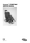
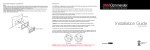
1
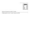
Tachometer Kit Fitting Instructions -Bonneville America
WARNING: Always have Triumph approved parts, accessories and conversions fitted
by a trained technician of an authorised Triumph dealer. The fitment of parts,
accessories and conversions by a technician who is not of an authorised Triumph dealer may
affect the handling, stability or other aspects of the motorcycle operation which may result in
an accident causing injury or death.
WARNING: Throughout this operation, ensure that the motorcycle is stabilised and
adequately supported to prevent the risk of injury from the motorcycle falling.
WARNING: Always ensure that newly installed wiring does not chafe against other
parts of the motorcycle such that they may be rubbed through and cause an electrical
problem. In addition, always ensure that newly installed wiring will not restrict steering
movement. Both conditions are hazardous and could give rise to a dangerous riding condition
resulting in a fire, loss of motorcycle control and/or an accident.
5*
6*
4
1
2
3
7*
WARNING: This kit is designed for use solely on Triumph Bonneville America
motorcycles and should not be fitted to any other Triumph model or motorcycles of
other manufacturers. Fitting this kit to any other Triumph models or motorcycles of other
manufacturers may interfere with the rider and could affect the stability and handling of the
motorcycle leading to an accident causing injury or death.
Parts Supplied
1.
Tachometer gauge . . . . . . . . . . . . . . . . 1
5.*
Harness . . . . . . . . . . . . . . . . . . . . . . . . . . 1
2.
Grommet . . . . . . . . . . . . . . . . . . . . . . . . . 1
6.*
Cable . . . . . . . . . . . . . . . . . . . . . . . . . . . . 1
3.
M5 dome nut . . . . . . . . . . . . . . . . . . . . . 1
7.*
Cable tie . . . . . . . . . . . . . . . . . . . . . . . . 15
4.
M5 washer . . . . . . . . . . . . . . . . . . . . . . . 1
*
To identify if items 5, 6 and 7 are required, check the following:
If the fuel tank console harness has 3 connectors (1 x male 3 pin connector, 1 x male 2 pin
connector and 1 x female 2 pin connector) then the fitment of items 5, 6 and 7 is not required.
If the fuel tank console harness has only 2 connectors (1 x male 3 pin connector, 1 x male 2
pin connector) then items 5, 6 and 7 are required to replace the existing harness.
Instructions part number A9900165 issue 3, ADC 9979
E Triumph Designs 2010
1
Tachometer Kit Fitting Instructions -Bonneville America
1. Undo the two screws located under the rear of
the seat and remove the seat.
7. Insert one end of the cable supplied with the
kit into the igniter connection block as shown
below.
2. Disconnect the battery, disconnecting the
negative (--) lead first.
Motorcycles requiring fitment of items 5, 6
and 7
2
3. Turn the fuel tap OFF and disconnect the hose
from the tap.
WARNING: Observe the warning
advice given in the service manual
on the safe handling of fuel and fuel
containers.
1
A fire, causing personal injury and damage
to property could result from spilled fuel or
fuel not handled or stored correctly.
1. Cable
2. Igniter connection block
4. Slacken and remove the fuel tank mounting
bolts.
8. Route the cable as shown below. Secure the
cable to the main harness and frame at regular
intervals using the cable ties supplied with the
kit.
1
T908.APS.02
1. Fuel tank mounting bolts
5. Disconnect the breather hose from the
right--hand side of the tank.
NOTE: On California models, this hose is
the evaporative loss system hose. Plug
the hose end whilst it is disconnected.
6. Remove the fuel tank, taking care not to lose
the mounting rubbers.
2
Tachometer Kit Fitting Instructions -Bonneville America
9. Locate the main harness instrument
connector block. Insert the free end of the
cable into the top row of the connector block
3rd from the left as shown.
1
12. From the underside of the console, push out
the tachometer blanking plug.
Fit the
grommet to the tachometer mounting post as
shown below. Align the tachometer location
peg with the hole in the mounting post and
secure using the domed nut and washer
supplied with the kit. Tighten the domed nut
to 3 Nm.
2
1. Cable
2. Instrument connector block
All motorcycles
1. Grommet
2. Washer
3. Domed nut
10. Release the screws securing the warning light
console to the fuel tank.
Motorcycles requiring fitment of items 5, 6
and 7
13. Carefully prise each warning light lens from
the upper side of the console.
2
1
2
T908.PIC07
1. Console
2. Screws
11. Raise the console and disconnect the
multi-plug connector joining the warning light
harness to the main harness.
1
T908.PIC06A
1. Warning light lens
3
Tachometer Kit Fitting Instructions -Bonneville America
14. Remove the warning light harness from the
console.
NOTE: The warning light harness will not
be refitted but should be retained for
future re-use if the tachometer kit is ever
removed.
15. Identify the function of each bulbholder in the
replacement warning light harness by
reference to their wire colours as follows:
All motorcycles
18. Position the console to the fuel tank and
reconnect the multiplug connector joining the
warning light harness to the main harness.
19. Connect the tachometer to the main harness
or newly fitted cable as appropriate.
20. Fit the console and tighten its screws to 5 Nm.
Motorcycles fitted with items 5, 6 and 7
21. Ensure the fuel tank front mounting rubbers
are correctly fitted to the frame then refit the
tank.
Function
Wire colour
Low oil pressure
warning light
White/brown and
green/red
Neutral indicator light
Black/white and
green/red
High beam indicator
light
Blue/white and brown
Turn indicator light
Green/white and
green/red
1
16. Fit the replacement harness to the console
locating the bulbholders in the positions
shown below.
1
3
T908.APS.07
1. Fuel tank front mounting rubbers
22. Securely reconnect the fuel hose and
breather hose to the tank. On California
models connect the evaporative loss system
hose.
2
23. Ensure the collars and rear mounting rubbers
are correctly fitted then install the fuel tank
mounting bolts, tightening them to 9 Nm.
4
24. Turn the fuel tap ON and check for fuel leaks.
All motorcycles
1. Low oil pressure warning light
25. Reconnect the battery,
positive (+) terminal first.
2. Neutral indicator light
3. High beam indicator light
connecting the
4. Turn indicator light
26. Check for correct operation of all tell-tale lights
and instrument illumination.
17. Refit the warning light lenses.
27. Check for correct operation of all other lighting
and light signalling devices.
28. Install the seat, tightening its screws to
10 Nm.
4