1
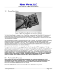
Data buoy operations safety On the 18th October 2012 a Fugro staff member was fatally injured during the recovery and maintenance of a Fugro OCEANOR Wavescan buoy offshore Malaysia. The buoy in question was deployed in August 2010, and visited for cleaning in November 2010. It was reported that the buoy was soiled with bird droppings. At some point after this, the maintenance program for the buoy was suspended. The program was re-established in 2012, and the accident took place on the initial maintenance cruise. After retrieval onto the service vessel, the buoy was cleaned, and the task of opening the instrument compartment started. This compartment also holds the lead-acid battery packs of the buoy. Access to the instruments is gained by removing a circular lid which is secured by 16 bolts. The removal of the bolts had been completed, except for the last bolt which proved to be seized. The decision was made to free this bolt using an angle grinder. Only moments after applying the grinder, an explosion took place which resulted in the lid blowing open and the instrument modules and their mounting plate being projected outwards with great force striking the employee and causing fatal injuries. The initial report from manufacturer concluded that the explosion was caused by sparks from the grinder igniting an explosive mixture of hydrogen and oxygen which had built up inside the compartment. The hydrogen build-up was assumed to stem from the lead-acid batteries. The subsequent design review resulted in a list of safety barriers which could or should have prevented the accident. The list below can at the same time serve as a check list for measures that will be made available by Fugro OCEANOR. It should be noted that bird spikes and a protective cover was scheduled for installation on the buoy in question. Warning in manual against ignition sources (Was in place) Instructions in manual on purging the instrument compartment (Was in place) Protective cover over instrument compartment lid (Was available) Bird spikes (Was available) Warning sign (Available now) Improved purging arrangement (Available now) Clearer instructions in manual (Available soon) Clearer instructions are under preparation and will be made available here. These instructions will emphasize that the buoys at all times should be treated with the assumption that they could contain an explosive gas mixture, and the following precautions taken: Updated: 3/22/2013 09:48 Page 1 Exercise particular care with buoys that have not operated normally in the period prior to retrieval. Examples are buoys that have not transmitted data, buoys that are physically damaged, and buoys that have not been subject to the required maintenance Equalise the pressure inside the buoy to the ambient air pressure by opening the gas filling valves Purge the interior of the buoy with air or nitrogen in order to remove any possibility of hydrogen gas. The flushing procedure is described in the Wavescan user manual Do not allow any ignition source near the buoy until it is fully opened. This certainly includes power tools. Do not smoke in the vicinity of the buoy Keep your distance. Only the minimum required number of persons should be in the vicinity of the buoy until it is fully opened. Never stand in direct line of the instrument compartment lid. When flushing has been completed, proceed immediately with the opening of the lid Leave the lid fully open for a further 10 minutes Please note that the Wavescan buoy is still safe for use provided the maintenance and handling procedures are followed correctly. The full report from the manufacturer can be found here: FOASsafetyalert_GMO_v4_doc.pdf The panel requests both manufacturers and buoy operators to keep it informed of the improvements being carried out towards buoy safety, so that it in turn can inform all other operators of these as a part of its technical information exchange function, in the interests of the whole community. Information on current manufacture and maintenance recommendations will be placed in this web page. Buoy operators and manufacturers are urged to take above information into account. Annex: Earlier Incidents NIOT (information provided by the DBCP and Dr. Premkumar) Following an explosion in August 2001 of a moored data buoy during maintenance onboard a ship in the Bay of Bengal which resulted in the death of a crew member, the Indian National Institute for Ocean Technology (NIOT) who operated the buoy convened an expert committee to examine the incident. The committee included distinguished scientists in mechanical and electrical engineering, battery development and manufacture, forensic science and pressure vessels. This committee had concluded that the explosion was due to the emission of hydrogen and oxygen from overcharged batteries, ignited by an electrical spark. The recommendations of the expert committee were then placed before the Data Buoy Cooperation Panel and the issue was discussed further with the buoy operator represented by Dr. Premkumar (NIOT India), Panel Members, and manufacturers at its 17th session in Perth, 22-26 October 2001. Report from manufacturer also suggested that likely causes of the explosion were: Updated: 3/22/2013 09:48 Page 2 1. The release of hydrogen gas from the batteries inside the instrument cylinder, resulting from their being overcharged; 2. A temperature rise in the batteries resulting from the buoy being kept on deck for 1.5 hours, leading to the generation of hydrogen beyond an acceptable limit; 3. A spark generated in the electrical circuit. After discussion, the panel recommended that manufacturers should enhance buoy safety through improved design in the following areas 1. Batteries are to be placed in a vented compartment, eliminating voids as much as possible, with a double venting arrangement; 2. Incorporation of an overcharge controller and temperature controlled switch, to disconnect the batteries from the solar panels when required; 3. Incorporation of an explosive gas sensor and temperature sensor inside the battery compartment and instrument cylinder, with the data to be transmitted once a day, to allow corrective action, or suitable explosive gas testing procedures, to be undertaken on buoy retrieval or servicing; 4. Incorporation of continuous monitoring of battery charge current and voltage, to be transmitted with the buoy data; 5. Incorporation of a suitable purging system and procedures. UK Met. Office (information provided by Wynn Jones): Some years ago UK Met. Office had a buoy invert because the foot had been removed by fishermen or other unauthorised persons. When the buoy was eventually retrieved after it had drifted ashore there was some evidence that some of the batteries had come loose and had shorted against the steel lid of the container pod they are housed in, causing an explosion. However, the explosion was contained within the buoy hull which remained water tight. There was no injury to anyone and the buoy, and most of its electronics were reused. After that, UKMO modified the brackets that hold the batteries in place such that they will not move even if inverted. UKMO practise of housing them in their own stainless steel container which is itself inside the steel hull of the buoy probably minimises the consequences such an explosion can cause. NDBC (information provided by Eric Meindl and Bill Burnett): A short summary of findings and activities at NDBC with respect to dealing with explosive gases in moored buoys is given below. NDBC efforts began in 1988 when an aluminium buoy (6-m NOMAD type), returned from the field and just opened up within NDBC industrial facility, exploded. As a result, NDBC now uses meters to sample the interior of all buoys. NDBC have experienced one or two other explosions at sea with no injuries, and many incidents when technicians have taken air samples, found the situation dangerous, and implemented special procedures to vent the buoy. Information below addresses specifically the NDBC buoys, which are vented systems, not sealed as other systems might be. Nevertheless, there may be some information others can use to make their procedures safer. Updated: 3/22/2013 09:48 Page 3 NDBC also has specific, detailed reports of their experiences and what they know. These can be made available upon request. Summary of NDBC Buoy Power System Flammable Gas Problems and Solutions 1. Hydrogen gas generation in buoys: 1. Hydrogen gas mixtures in air are flammable between 4% and 75% by volume 2. Accumulation rates increase with poor buoy ventilation (water intrusion blocks the lower center compartment vent) 3. Electrolysis (the conductive path is from the positive terminal, through seawater moisture on the exterior of batteries to the buoy hull). 4. Reduction of battery electrolyte (potassium hydroxide and zinc), aluminum and seawater. The primary batteries are located near the bottom of the buoy center compartment. 5. Normal charging of secondary batteries and discharging of primary batteries 6. Microbial induced corrosion 2. Hydrogen Gas Generation Past Incidents: SSC/6N03 44013/3D22 46027/3D24 46013/3D21 43D34/3D34 46030/3DV07 46014/3D59 42035/3D24 42039/3D56 1988 12 Sep. 97 14 Oct. 97 30 Oct. 97 11 Nov. 97 21 Sep. 99 3 Oct. 99 3 Nov. 99 6 Nov. 00 Explosion resulted in one death & one injury (a) Buoy returned to SSC with 100% LEL Caustic residues in bottom of compartment (b) Caustic residues; 100% LEL in 4 voids (b) Caustic residues; 100% LEL in void #2 (b) Buoy exploded prior to a service visit Buoy Exploded during service visit (b) 100% LEL due to plugged vents (b) 100% LEL in a compartment; stuck vent valves (a) The generation of hydrogen was caused by impurities in the primary batteries received from the manufacturer. (b) The generation of hydrogen was caused by seawater intrusion into the battery compartment. 3. Hydrogen Gas Mitigation: 1. Obtained expert Marine Chemist Consultants 2. Improved tests of buoy hatch and cable penetrations 3. Installed a third battery compartment vent tube (if the buoy leaks, the lower vent ) is blocked by water 4. Improved watertight integrity of hatch gaskets and multiplug penetrations 5. Increased buoy freeboard 6. Improved equipment compartment ventilation 7. Installed a seal fence to reduce excessive loading on hatch covers Updated: 3/22/2013 09:48 Page 4 8. Provided sufficient clearance between the hatch cover lip and the dog-bolt tabs 9. Improved hatch gasket deficiencies (insufficient gasket stiffness, gaps in the hatch gasket joint, and the position of the gasket joint relative to the bow of the buoy) 10. Filled voids with inert gas 11. Maintain safe entry procedures and training 12. Installed explosive gas sensors (FAA) 13. Deduced the use of primary batteries.The future goal is to discontinue the use of primary batteries. 14. Bilge pumps (not yet implemented) Updated: 3/22/2013 09:48 Page 5