1
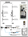
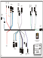
Circuit
Breaker
Intput
Circuit
Breaker
Output
Left Hand
Limit Switch
Housing
Connections
#1 Relay
Connections
Right Hand Limit
Switch Connections
on Radiator
Support
Left Hand
Motor
Connector
Right Hand
Limit Switch
Housing
Connections
6.5
DIODE
HARNESS
CONN
Right Hand
Motor
Connector
American Autowire / Factory-Fit
800-482-9473
Ground
12 Volt
Battery
Source
Classic Update Series
1967 Camaro
#2 Relay
Connections
bag
Rally Sport Headlight
Connection Kit
500687
Page 1
#3 Relay
Connections
Left Hand Limit Switch
Connections on Radiator
Support
92966546 instruction rev 0.0 1/13/2005
CONNECTION TO LIMIT SWITCHES
CONNECTION TO RELAY PANEL
- If using after market limit switches, connect as shown in DIAGRAM "A"
- If using original GM limit switches, connect as shown in DIAGRAM "B".
Driver Side Limit Switch - OUTER - Gray
Driver Side Limit Switch - INNER - Purple
Passenger Side Limit Switch - OUTER - Dark Green
Passenger Side Limit Switch - INNER - Light Green
Driver Side Limit Switch - OUTER - Gray
Driver Side Limit Switch - INNER - Purple
Passenger Side Limit Switch - OUTER - Dark Green
Passenger Side Limit Switch - INNER - Light Green
Relay #3
Orange Power lead from
Relay #1connections
12 volt
battery power
The difference between the GM switch and
aftermarket replacement switches is the indexing
tab. By having an index tab the upper and lower
wires cannot be mis-indexed. The purpose of this
diagram is to prevent mis-indexing on the aftermarket
switches.
Relay #1
Relay #2
10 amp
circuit breaker
Connect this lead to a
good chassis ground
Connect this lead to a
good chassis ground
Indexing Tab
Driver Side Limit Switch - OUTER - Brown
Driver Side Limit Switch - INNER - Dark Blue
Passenger Side Limit Switch - OUTER - Brown
Passenger Side Limit Switch - INNER - Dark Blue
Driver Side Limit Switch - OUTER - Brown
Driver Side Limit Switch - INNER - Dark Blue
Passenger Side Limit Switch - OUTER - Brown
Passenger Side Limit Switch - INNER - Dark Blue
DIAGRAM "A"
DIAGRAM "B"
RALLY SPORT DIODE HARNESS CONNECTIONS
Remove existing brown wire and terminal from
ignition switch, plug it into the female connector,
then plug this assembly into the male connector
on the RALLY SPORT DIODE HARNESS.
Diode
Harness
Connection
Plug this brown wire and terminal into the original
cavity of the ignition switch from which you just
removed the brown wire and terminal above.
Remove existing power wire and terminal to the dimmer switch
(light blue or yellow wire), plug it into the female connector,
then plug this assembly into the male connector
on the RALLY SPORT DIODE HARNESS.
American Autowire / Factory-Fit
800-482-9473
Classic Update Series
1967 Camaro
bag
Rally Sport Headlight
Connection Kit
500687
Page 2
Plug this light blue wire and terminal into the original
cavity of the headlight switch from which you just
removed the power wire and terminal above.
92966546 instruction rev 0.0 1/13/2005
1967 Camaro RS Headlamp Doors
The material presented here supplements the coverage given in the 1967 Chassis Service Manual on Camaro headlamp
doors. The Camaro headlamp door system consists of the following components.
The Control Circuit, used to switch the operating relays, which consists of:
a. Main light switch
b. Ignition switch
c. The energizing coils of the three relays
d. The harness between the above
e. A one-way diode in the ignition switch side of the harness
f. The headlamp filaments to ground
The doors open as follows:
1.
The Control Circuit is energized when the headlamps are turned on (through the light blue wire). Relay coil
R1 is energized to ground at headlamp ground wire. Relay coils R2 and R3 are not energized because the
one-way diode prevents a complete ground path.
2.
The motor Operating Circuit is as follows:
a. From power source at horn relay junction, to
b. Circuit breaker on mounting plate to
c. Relay R1 lower contacts (relay energized) to
d. Limit switches on radiator support, to
e. Door motor, to
f. Limit switches on door assemblies, to
g. Relay R3 upper contacts (relay not energized), to
h. Ground at radiator support
3.
The doors move from closed to open and bottom against the limit switches on the radiator support. The limit
switch movement breaks the circuit and the door motors stop in the open position.
The doors close as follows:
1.
The Control Circuit is energized when the headlamp switch is "OFF" and the ignition switch is "ON". Relay R1 is
not energized. Relays R2 and R3 are energized through the ignition switch through the one-way diode, the relay
coils, the headlamp switch terminal, the dimmer switch, and finally through the sealed beam filaments to ground.
2.
The motor Operating Circuit is as follows:
a. Power from source at horn relay junction, to
b. Circuit breaker on mounting plate, to
c Relay R1 upper contacts (relay is not energized), to
d. Relay R2 lower contacts (relay energized), to
e. Limit switches at door assemblies, to
f. Door motors, to
g. Limit switches at door assemblies, to
h. Relay R3 lower contacts (relay energized), to
i. Ground at radiator support
3
When doors move to the closed position they bottom against the limit switches on the lamp assemblies.
This limit switch movement breaks the circuit and the door motor stops in the closed position.
Page 3
BLACK
DARK BLUE
BROWN
FIREWALL
DIMMER
SWITCH
R3
R1
PATH OF DOOR
HINGE
2.
HEADLIGHT
SWITCH
GREEN
BROWN
IGNITION
SWITCH
UNDER
DASH
CONNECTOR
LIMIT SWITCH
RADIATOR
SUPPORT
R2
ORANGE
ACC.
DIODE
Theory or Operation
Two separate electrical circuits are used to operate the headlamp doors. The two circuits are:
The headlamp door motor Operating Circuit which consists of:
a. Power source at the horn relay junction block
b. A 10-amp circuit breaker
c. Three switching relays
d. Two limit switches at each door
e. A motor at each door
f. A harness connecting the above
CIRCUIT
BREAKER
RED
In General
The doors open anytime the main light switch is pulled on to the headlamp position. The doors will close only when the
ignition switch is in the "ON" or "ACC" position and the main light switch is "OFF".
1.
BROWN
HORN
RELAY
BROWN
The operation of the headlamp doors is as follows:
NO WIRE
BAT
LT. BLUE
6.
7.
The Main Light Switch turns the headlamps on and actuates the door opening motor circuit.
The Ignition Switch actuates the door closing circuit. The doors will not close with the ignition switch off.
A One-Way Diode in the ignition switch door relay actuating circuit, limits current flow to one direction.
A Circuit Breaker to protect the motor circuits is located on a panel under the left front fender.
Three Identical Relays to reverse the direction of door motor circuit, as needed for opening or closing,
are mounted on a panel under the left front fender.
Two Reversible Motors that operate each door. Each motor is equipped with an integral circuit breaker.
Limit Switches to turn off the motors as the doors each full travel in either direction. Two switches are mounted
at each door location.
FIREWALL
1.
2.
3.
4.
5.
LIMIT SWITCH
HEADLIGHT ASSY.
+
LIMIT SWITCH
RADIATOR
SUPPORT
SEALED
BEAM
LIMIT SWITCH
HEADLIGHT ASSY.
OPERATING CIRCUIT
CONTROL CIRCUIT
CAMARO HEADLAMP DOOR WIRING - SYSTEM IN "CLOSED" POSITION.
Classic Update Series
1967 Camaro
bag
Rally Sport Headlight
Connection Kit
American Autowire / Factory-Fit
800-482-9473
500687
92966546 instruction rev 0.0 1/13/2005
Headlamp Door Diagnosis
Functional Test
The following three steps should be performed during new car preparation or before any detailed diagnosis is
performed.
I. Start with ignition and headlamp switch both OFF .
II. Pull headlamp switch to the headlight "ON" position and check to see that:
A. Headlamps come on. This circuit is needed to close the doors.
B. Headlamp doors open
1. if they open, one half of the control is ok go to step III.
2. If they don t open, the add on harness for this option may not be connected at:
a. Double connector under dash.
b. Main light switch (light blue wire).
3. If they don t open (and step two is ok) turn the ignition key to ON and observe the doors.
a. If they are open, the one way diode is shorted or,
b. There may be a short in the brown wire to the ignition switch or,
c. The circuit breaker may be defective (possibly caused by a shorted diode or low relay voltage).
III Start the engine and operate the light switch a number of times to test the lap and door operation. This
eliminates a possible marginal voltage condition at the relays if the battery is slightly low. Listen for relay click
noise as the headlamp switch is operated from on to off. Also listen for circuit breaker click if the doors fail to
function. A circuit breaker click indicates a short in the system.
Detailed Diagnosis
If the above mentioned steps do not pinpoint the problem, continue diagnosis as follows:
If neither door opens; look for a defect in area common to both motors.
A. Check black ground wire from relay R3 to ground at radiator support. This is the motor ground path.
B. Check to see that Relay R1 is energized by unplugging the two wire connector. The relay should click as
connector contact is broken and made. If not, use a test lamp between the two terminals of the two-wire
connector. The lamps should light up if the wiring is ok and headlamp switch is "ON". If it does, replace relay R1.
C. Check to see that relay R3 is not energized by unplugging the two wire connector. The relay should not click
when connector contact is broken and made. If the relay does click, there is a possible short in the brown wire
to the ignition switch in combination with a broken wire such as might occur in a pinch condition. Check with a
test light between ground and each terminal of the two-wire connector. The test light should light both times.
D. Use a test light and check from ground to the following terminals (test light should light up):
Terminal
Problem if test light does not light
Horn Relay
Open circuit between battery and horn relay
Circuit breaker red
wire terminal
Bad red wire or connector
Circuit breaker orange
wire terminal
Bad circuit breaker
Relay R1 orange wire
Bad orange wire
If neither door closes when lights are turned off, check for voltage at the green wire terminal on Relay R1 (use test
lamp to ground) Note: ignition switch must be ON to energize system and the engine should be running during checking
operation.
A. If there is voltage at green terminal, check for voltage further along the harness towards the motors. If there is
no voltage at the brown wire terminal of Relay R2, the R2 and R3 (they are wired in parallel) are not actuated.
Check for 12 volts across the two-terminal connectors of both relays (use one test light lead at each terminal of
connector).
1. If voltage is present, replace R2.
2. If no voltage, check wiring back to the ignition switch making sure that the diode is not open or in backwards.
B. If voltage is pulsating, due to action of circuit breaker, then R2 has pulled in but R3 has not. Check for 12 volts
across the two-terminal connector of R3 (one test light lead at terminal connector). If voltage is present, replace
R3.If no voltage, check wiring.
If one door does not operate the same as the other, look for a malfunction in that particular door s motor, switches or
wiring.
Door does not open
A. Check for mechanical binding. If motor is being prevented from turning, a flashing blue light in its terminal
housing will indicate that the motor s thermal overload switch is operating.
B. Check for voltage between limit switch (on radiator support) and motor. Use test light from top limit switch
terminal ground.
1. If no voltage is present:
a. Check connections at top and bottom of limit switch.
b. Check wiring from relay R1 to bottom of limit switch using test light at bottom terminal of light switch.
Test light should light.
c. Replace limit switch if bad.
2. If there is voltage present, check for voltage between motor and limit switch on headlamp assembly.
If voltage is present:
a. Check connections at top and bottom of limit switch.
b. Check wiring between bottom of limit switch and ground at relay R3.
c. Replace limit switch of headlamp assembly if bad.
Door does not close
A. Check for mechanical binding
B. Check for voltage between limit switch and headlamp assembly and motor:
1. If no voltage is present:
a. Check limit switch connections - top and bottom
b. Check wiring from relay R2 to bottom of limit switch. Use test lamp from terminal to ground.
c. Replace switch if bad.
2. If there is voltage present, check for voltage between motor and limit switch at radiator support.
If voltage is present:
a. Check limit switch connections - top and bottom.
b. Check wiring from bottom of limit switch to ground at relay R3.
c. Replace limit switch if bad.
Motor does not stop running at end of door travel.
After a few seconds of stall, the motors thermal overload will start flashing in the terminal housing of the motor.
Check for sufficient contact between the door mechanism and the appropriate limit switch for proper switch operation.
Push in the switch button to insure operation; if motor continues to flash (operate) replace the switch.
Door moves jerkily.
A. Check for loose connection in circuit.
B. Check for mechanical bind in the door mechanism (the motor s thermal overload will probably be flashing)
Headlight Door Adjustment
The headlight door adjustment is proper when:
A. There is clearance all the way around the door in the closed position.
B. The limit switch is actuated to shut off the door motor.
C. The door is flush in the opening.
Adjustments can be made as follows:
A. The door cover is retained by 4 screws threaded into caged nuts. These nuts have up to .090 movement for
door cover adjustment when the screws are loosened. Use this adjustment to square the door in the opening
by measuring clearance (.025 - .050 ) all the way around.
B. If the door assembly is cocked at an angle (down or up) in the opening, shim the assembly at its radiator
support mounting screws.
C. Adjustment of the limit switch, if needed, can be obtained by slotting the mounting bracket holes with a round
file. This should be used only when the other adjustments fail to provide better than marginal
clearance around the door.
Classic Update Series
1967 Camaro
C. If there is no voltage at green wire terminal of relay R1 (use light test to ground), check for voltage at orange wire
terminal or R1.
1. If voltage is present, replace R1
2. If voltage is not present, check for open circuit breaker or wiring.
Rally Sport Headlight
Connection Kit
American Autowire / Factory-Fit
800-482-9473
Page 4
bag
500687
92966546 instruction rev 0.0 1/13/2005