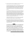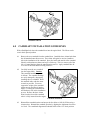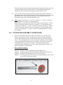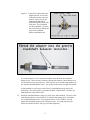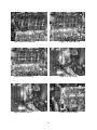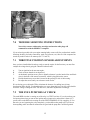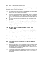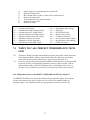
1
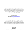
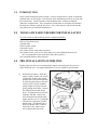
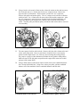
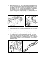
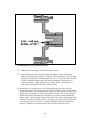
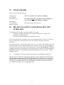
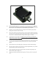
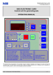
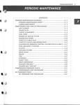
Camshaft Installation Instructions
For Installing:
Part # 65206 – 1997-2004 (5.7L) LS-1 Engines
Perfect Performance Products, LLC
Painless Performance Products Division
2501 Ludelle St. Fort Worth, Texas 76105-1036
(800) 423-9696
We have attempted to provide you with as accurate instructions as
possible, and are always concerned about corrections or improvements
that can be made. if you have found any errors or omissions, or if you
simply have comments or suggestions concerning these instructions,
please write us at the address on the cover and let us know about them.
Or, better yet, send us a fax at (817) 244-4024.
For Technical Questions
E-mail address: [email protected]
Tech Line: (800) 423-9696
Perfect Performance Products, Inc. shall in no event be liable in
contract or tort (including negligence) for special, indirect, incidental or
consequential damages, such as, but not limited to, loss of property
damage, or any other damages, such as, cost or expenses which might be
claimed as the result of the use or failure of the goods sold herby, except
only the cost of repair or replacement.
February 2006
Revision #1
Copyright © 2006 by Perfect Performance Products, LLC.
2
1.0
INTRODUCTION
Please read all instructions prior to install. Use these instructions as a guide to install the
camshaft into your LS1 engine. Not all facets of the installation process are covered with
these instructions. Certain elements of the installation have a number of different
methods to complete them. These instructions include what we at Painless Performance
Products have found to work the best for us. You, as the end user, will decide what the
best method for your camshaft installation is.
2.0 TOOLS AND PARTS NEEDED FOR INSTALLATION
You will at least need the following for this camshaft installation:
Full set of mechanics tools
Camshaft lube
Silicone gasket sealant
Carburetor cleaner
New gaskets for the water pump (required)
New gaskets for the valve covers, front engine cover and crankshaft front oil seal
(It is recommended but not required to replace these gaskets.)
New crankshaft balancer bolt (required)
3.0 PRE-INSTALLATION GUIDELINES
During engine tear down it is recommended to inspect each engine part for excessive
and/or abnormal wear. See engine manufacturer’s service manual for specifications.
3.1
Disconnect the battery. Drain the
engine coolant. Remove the air-box
if applicable. Remove the coolant
passage hoses from the throttle body
by squeezing the clamps with a pair
of pliers (only if factory installed
spring clamps are being used) and
gently pulling on the hoses. Remove
the radiator hoses and the heater
hoses. Twisting the hoses back and
forth may aide this. Remove the
PCV tubing from the throttle body,
intake and valve covers. Unplug the
TPS and IAC connectors from the
throttle body. The throttle body is
held on with three bolts. Remove
these bolts with a 10mm socket
and set the throttle body aside.
PCV routing
3
3.2
Using a break-over bar and a 15mm socket, release the tension on the main accessory
drive belt and remove it. Do the same for the A/C compressor belt. Remove the
upper and lower coolant hoses. Set them aside. Remove the A/C compressor,
bracket, idler puller and tension pulley. The A/C compressor is held onto its bracket
with four bolts. Use a 15mm socket to remove these bolts and the compressor. After
the A/C compressor is removed, access is gained to the four bolts holding the A/C
compressor bracket to the engine block. Remove these four bolts with a 15mm
socket. The idler pulley and tension pulley are bolted to this bracket and are removed
as an assembly.
Corvette belt routing
Camaro belt routing
3.3
The water pump is held on with six bolts. Remove the bolts with a 10mm socket and
set the water pump aside. Now is a good time to clean the left over water pump
gasket from the engine block. Use extra care when cleaning this sealing surface.
Any scrapes or gouges of the aluminum will hinder the new gaskets sealing ability.
Make sure none of the old gasket scraped from the engine block enters the coolant
passages of the engine block.
3.4
Using a 24mm impact socket and an impact wrench remove the crankshaft balancer
bolt. Do not discard this bolt. Using a two or three jaw puller, pull the crankshaft
balancer off of the crankshaft. Set the crankshaft balancer and bolt aside.
Crankshaft balancer bolt removal
Crankshaft balancer pulley removal
4
3.5
Remove the front engine cover. There are eight bolts threaded from the front of the
cover into the engine block and two bolts threaded from the bottom, through the oil
pan and into the front engine cover. Remove these bolts with a 10mm socket. Set
the front engine cover aside. Reinstall the crankshaft balancer bolt into the front of
the crankshaft. Use a break over bar and a 24mm socket to turn the engine
clockwise. Turn the engine until the alignment dot on the camshaft sprocket is at 6
o’clock and the alignment dot on the crankshaft sprocket is at 12 o’clock. This is top
dead center number one cylinder. Doing this will aide in the installation of the
camshaft.
Bottom front engine cover bolts
Front engine cover removal
3.6
Unplug the spark plug wires from the spark plugs. Remove the valve covers. Set the
valve covers aside.
3.7
Using a 10mm socket loosen the rocker arm bolts enough to turn them to the side of
each valve spring. Once the rocker arms are turned to the side, you can remove the
pushrods just by pulling them up and out of the engine. Set the push rods aside.
3.8
The camshaft sprocket is attached to the camshaft with three bolts. Use a 10mm
socket to remove these three bolts and the camshaft sprocket. Set them aside. The
camshaft chain will fall down onto the crankshaft sprocket. Just leave the chain there
for now. Behind this camshaft sprocket is the camshaft retainer. Remove the four
bolts and this retainer.
Camshaft sprocket removal
Lifters and lifter cups
5
3.9
Removal of the camshaft. Before the camshaft can be removed, the lifters must be
moved out of the way. There are several different ways to do this.
First, under the engine heads there are lifter cups. When the camshaft is spun several
times clockwise the lifters will go up into these cups. Friction between the lifters and
the lifter cups usually holds the lifters up out of the way of the camshaft so it can be
removed. But, sometimes this friction is not enough to hold the lifters up into the
lifter cups and the lifters drop back down onto the camshaft. So, this method is not
fail-safe and should be used cautiously if at all. If this method is chosen, spin the
camshaft at least 5-6 times clockwise. At this point the lifters should be up in the
lifter cups.
The second method to holding the lifters up and out of the way involves magnets. If
this method is chosen, 16 telescoping magnet pens with pocket clips will need to be
purchased. The magnetic end of the pen needs to be small enough to fit through the
pushrod hole in the engine head and long enough to reach the top of the lifter.
Extend the magnet pens down into the pushrod holes. When the magnet pens reach
the lifters they will attach themselves to them. Spin the camshaft clockwise to push
the lifters up while holding up on the magnet pen. Bend pocket clip 60 degrees from
the magnet pen and use this to hold the magnet pen and lifter up by wedging it to the
engine head. A twenty inch board laid length wise on the engine head can also be
used as a table for the magnet pen pocket clips to rest on.
A third way to hold the lifters up out of the way of the camshaft is to buy specially
manufactured LS1 camshaft swap tools. A search on the internet will lead you to
these specialty tools and their manufactures for purchase information.
3.10 Use one of the three methods of choice listed above to move the lifters out of the way
of the camshaft. To aide in the removal of the camshaft from the engine you will
need to thread three long bolts into the end of the camshaft to use as a handle. The
water pump bolts work well for this application. Or, you can use a camshaft removal
tool. Use the three 10mm bolts in the end of the camshaft as a handle and remove the
camshaft out of the motor.
Caution:
This camshaft removal process is delicate. Four bearings must be
passed through with the camshaft lobes. Each camshaft lobe has
sharp edges. These sharp edges will gouge the bearings and
permanently damage them. Hold the camshaft inline with the
motor as much as possible when pulling it out. You must support
the weight of the camshaft against gravity and float it out of the
engine. Twisting the camshaft back and forth may aide in this
removal process. If the camshaft does not want to come out, push
it back in and give it a few more turns to make sure the lifters are
not holding it. Do not forcibly pull the camshaft out of the engine.
6
Camshaft removal
4.0 CAMSHAFT INSTALLATION GUIDELINES
With a flashlight look down the camshaft bore into the engine block. The lifters can be
seen in their upward position.
4.1
Remove the new camshaft from the camshaft box. Install the three 10mm bolts from
the old camshaft onto this new one. These bolts will again be used as a handle to
aide in the installation of the camshaft. Spray the inside and outside of the camshaft
liberally with carburetor cleaner and wipe it with a rag. This is to remove all of the
left over metal shavings from the manufacturing process. Apply camshaft lube all
over each of the lobes and the bearing surfaces.
4.2
Carefully insert the new camshaft
into the engine block. Caution:
This camshaft installation process
is delicate. The camshaft bearings
are easily damaged by improperly
installing the new camshaft. Hold
the camshaft inline with the motor
as much as possible. You must
support the weight of the camshaft
against gravity and float it into the
engine. Twisting the camshaft back
and forth may aide in this installation
process. Remove the three 10mm
bolts from the front of the camshaft
after it is fully inserted into the engine.
Camshaft installation
4.3
Reinstall the camshaft retainer and torque the four bolts to 18 lb/ft (25Nm) using a
10mm socket. Reinstall the camshaft sprocket by aligning the alignment dot on it to
6 o’clock. The crankshaft alignment dot should still be in the 12 o’clock position.
7
Wrap the camshaft chain around the camshaft sprocket and align the dowel pin on the
camshaft to the hole in the camshaft sprocket. Thread the three camshaft bolts
through the sprocket into the cam and torque them to 26 lb/ft (35 Nm).
4.4
If you used the telescoping magnet method to hold the lifters, remove them now.
Reinstall the push rods. Gently push on the push rods until the lifters push down onto
the camshaft lobes. Make sure the pushrods are correctly aligned to the lifters.
Realign the rocker arms to the pushrods and the valves.
4.5
Note: Engine firing order is 1, 8,7,2,6,5,4,3. Cylinders 1, 3, 5 and 7 are on the left
bank. Cylinders 2, 4, 6 and 8 are on the right bank.
With the engine at top dead center number one cylinder do the following. Torque to
22 lb/ft (30 Nm) the exhaust rocker arms of cylinders 1, 2, 7 and 8 and the intake
rocker arms of cylinders 1, 3, 4 and 5. Rotate the crankshaft 360 degrees. Torque to
22 lb/ft (30 Nm) the exhaust rocker arms of cylinders 3, 4, 5 and 6 and the intake
rocker arms of cylinders 2, 6, 7 and 8. Take the old crankshaft balancer bolt out of
the crankshaft.
5.0 ENGINE REASSEMBLY GUIDELINES
5.1
Replace the crankshaft front oil seal and the front engine cover seal at this time.
Apply a small amount of silicone into the corners where the oil pan, front engine
cover and the engine block mate. Install the front engine cover with the ten bolts
loosely. The crankshaft balancer is a press fit onto the crankshaft. Several methods
can be used to install this balancer onto the crankshaft. First method, use the old
crankshaft balancers bolt to make an adapter. This adapter adapts a generic
crankshaft balancer installation tool to work with this third generation engine. See
below for guidelines to make this tool.
How to make this adapter:
Step one:
Step two:
Step three:
Step four:
Purchase a generic crankshaft balancer installation tool.
Identify the threads where the crankshaft adapters thread into the tool.
Purchase a die with this thread and a tool to use the die.
Cut off the head of the bolt from the old crankshaft balancer bolt. Cut the
bolt as close to the head as possible.
8
Step five: Using the die that matches the
adapter threads, cut one inch
of threads onto the cut part of
the bolt. This gives you the
crankshaft threads (M16,
2mm thread pitch) on one side
of the bolt. This will thread
into the crankshaft. The other
side of the bolt will thread into
the generic crankshaft
balancer installation tool.
A second method is to use a longer bolt with the same thread as the crankshaft
balancers bolt. There are many websites offering bolts with the correct dimension or
a local hardware store may stock one. This bolt must be at least the same hardness as
the original crankshaft balancer bolt. Two to three inches more of length is desirable.
A third method is to gain access to the factory General Motors tools used by the
dealerships. The tool needed is part number J41665-2 and J41665-1 and they are
manufactured by Kent-Moore tools.
5.2
Install the crankshaft balancer using one of the above three methods. The nose of the
crankshaft should be recessed 0.094-0.176 inch into the balancer bore. Install the
new crankshaft balancer bolt. First torque the bolt to 37 lb/ft (50Nm). Second,
tighten the crankshaft balancer bolt 140 degrees more. A second person may be
needed to hold the flywheel with a pry bar while tightening.
9
Crankshaft balancer to crankshaft tolerance.
5.3
Tighten the ten front engine cover bolts to 18lb/ft (25Nm).
5.4
Scrape the old gasket off of the water pump. Reinstall the water pump onto the
engine block using the new gaskets. Torque the water pump bolts to 11 lb/ft (15Nm)
and then to 22 lb/ft (30 Nm). Reinstall the valve covers. Torque the bolts to 106lb/in
(12Nm). Reinstall the spark plugs wires onto the sparkplugs. Reinstall the A/C
compressor bracket. Torque the four bolts to 37lb/ft (50Nm). Reinstall the A/C
compressor and torque the four bolts to 37lb/ft (50Nm).
5.6 Reinstall the A/C compressor drive belt. Reinstall the main accessory drive belt.
Reinstall the throttle body and torque the three bolts to 106lb/in (12Nm). Reinstall the
coolant passage lines onto the throttle body. Plug in the TPS and IAC connectors to the
throttle body. Reinstall the PCV hoses onto the throttle body, valve covers and intake.
Reinstall the radiator and heater hoses and fill the system with coolant. Reinstall the
battery cables. Check all fluids and top off if needed. Start engine. Immediately check
for proper oil pressure (30-50 psi at idle). The engine will seem a bit noisy for the first
few seconds of run time. This noise is normal and should subside after the first few
seconds. Change the oil and filter after the first 100 miles with the new cam.
10
Painless Performance Limited Warranty
and Return Policy
Chassis harnesses and fuel injection harnesses are covered under a lifetime warranty.
All other products manufactured and/or sold by Painless Performance are warranted to
the original purchaser to be free from defects in material and workmanship under normal
use. Painless Performance will repair or replace defective products without charge during
the first 12 months from the purchase date. No products will be considered for warranty
without a copy of the purchase receipt showing the sellers name, address and date of
purchase. You must return the product to the dealer you purchased it from to initiate
warranty procedures.
Copyright © 2007 by Perfect Performance Products, LLC
11
Wire Harness Installation Instructions
For Installing:
Part # 65106 – 1997-2004 (5.7L) LS-1 Engines
Part # 65206 – 1997-2004 (5.7L) LS-1 Engines
Manual # 90538
Perfect Performance Products, LLC
Painless Performance Products Division
2501 Ludelle St. Fort Worth, Texas 76105-1036
(800) 423-9696
We have attempted to provide you with as accurate instructions as
possible, and are always concerned about corrections or improvements
that can be made. if you have found any errors or omissions, or if you
simply have comments or suggestions concerning these instructions,
please write us at the address on the cover and let us know about them.
Or, better yet, send us a fax at (817) 244-4024.
For Technical Questions
E-mail address: [email protected]
Tech Line: (800) 423-9696
Perfect Performance Products, Inc. shall in no event be liable in
contract or tort (including negligence) for special, indirect, incidental or
consequential damages, such as, but not limited to, loss of property
damage, or any other damages, such as, cost or expenses which might be
claimed as the result of the use or failure of the goods sold herby, except
only the cost of repair or replacement.
P/N 90538 Perfect Performance Manual November 2005
Revision #3
Copyright © 2005 by Perfect Performance Products, LLC.
2
TABLE OF CONTENTS
1.0
2.0
3.0
4.0
5.0
6.0
7.0
INTRODUCTION……………………………………………………………………4
ABOUT THESE INSTRUCTIONS………………………………………………….4
TOOLS NEEDED……………………………………………………………………5
PRE-INSTALLATION AND HARNESS ROUTING GUIDELINES………………5
GENERAL INSTALLATION INSTRUCTIONS……………………………………7
5.1
Grounding the Vehicle……………………………………………………….7
5.2
Rough Installation……………………………………………………………8
5.3
Harness Attachment………………………………………………………….8
5.4
Terminal Installation Instructions……………………………………………8
GM LS-1 SYSTEM WIRING HARNESS INSTALLATION INSTRUCTIONS……9
6.1
Dash Group Installation…….………………………………………………..9
6.2
Sensor and Relay Installation………………………………………………..10
6.3
Engine Group Installation……………………………………………………12
TROUBLE SHOOTING INSTRUCTIONS…………………………………………15
7.1
TPS Pre-Adjustments………………………………………………………..15
7.2
Fuel Pump Relay Check……………………………………………………..15
7.3
The “Check Engine” Light…………………………………………………..16
7.4
Retrieving Trouble Codes from the Computer………………………………16
7.5
When to call Perfect Performance Products Tech Line……………………..17
LIST OF FIGURES
FIGURE 4.1
FIGURE 6.1
FIGURE 6.2
FIGURE 6.3
FIGURE 6.4
FIGURE 6.5
FIGURE 6.6
FIGURE 6.7
FIGURE 6.8
FIGURE 6.9
FIGURE 6.10
FIGURE 6.11
FIGURE 6.12
FIGURE 6.13
FIGURE 6.14
FIGURE 6.15
FIGURE 6.16
ENGINE CONTROL MODULE…………………………………………….6
ASSEMBLY LINE DIAGNOSTIC LINK (ALDL) CONNECTOR………..10
HARNESS RELAYS...………………………………………………………11
HARNESS FUSEBLOCK…………………………………………………...11
MANIFOLD ABSOLUTE PRESSURE SENSOR (MAP)………………….13
KNOCK SENSOR…………………………………………………………...13
CAMSHAFT POSITION SENSOR…………………………………………13
OXYGEN SENSORS………………………………………………………..13
CRANKSHAFT POSITION SENSOR (CKP)………………………………13
DRIVERS SIDE COIL CONNECTOR……………………………………...13
INJECTORS 1,3,5,7 …………………………………………………………14
PASSENGER SIDE COIL CONNECTOR………………………………….14
INJECTORS 2,4,6,8 …………………………………………………………14
THROTTLE POSITION SENSOR (TPS)…………………...……………….14
IDLE AIR CONTROL (IAC)………………………………………………...14
ENGINE COOLANT TEMP. SENSOR (ECT)………………………………14
INTAKE AIR TEMP SENSOR (IAT)………………………………………..15
LIST OF TABLES
Table 4.1
Table 6.1
Table 7.1
Compatible Parts List…………………………………………………………7
GM LS-1 Engine Group Connections………………………………………...12
Diagnostic trouble Codes……………………………………………………..17
3
1.0
INTRODUCTION
Please read all instructions prior to install. You have purchased what we at Painless Performance
Products, Inc. believe to be the most up-to-date and easiest-to-install automotive fuel injection kit
on the market. It is designed for easy installation, even if you have no electrical experience.
This kit is designed to be a complete system for fuel injection on all stock General Motors LS-1
engine (non-throttle by wire motors). This includes all wiring that is need by the computer to
run and control the fuel injection system. Please note that the PERFECT computer does not have
the capability to control an electronic transmission. If you are running a 4L60E transmission you
will need to contact an aftermarket transmission company for that computer and wiring harness.
If you are running a 700 R4 trans. and would like to have the lock-up functions you can purchase
Painless Performance part # 60109 for that function.
Usually, the computer, fuse block, relays, ALDL and check engine light can easily be mounted
under the dash. Most of the wiring in the harness has been pre-terminated to the proper connector
and all wire is rated at 275˚F and has been GM color-coded.
This harness has been broken down into three major groups:
Engine Group
Includes wiring for the fuel injectors, coil plugs, sensors,
fuel pump and coil power wire.
Dash Group
Includes ignition feed and tach. wires, ALDL, check engine
light
Fuse block and Relay Group Includes wiring for the fuse block, fuel pump relay, a/c relay,
ignition relay, cooling fan relay ground and alternative fuel
ground wire.
2.0 ABOUT THESE INSTRUCTIONS
These instructions provide information for the installation of the 65106 LS-1 fuel injection wire
harness kit. The contents of these instructions are divided into major Sections, as follows:
1.0
2.0
3.0
4.0
5.0
6.0
7.0
INTRODUCTION
ABOUT THESE INSTRUCTIONS
TOOLS NEEDED
PRE-INSTALLATION AND HARNESS ROUTING GUIDELINES
GENERAL INSTALLATION INSTRUCTIONS
GM LS-1 SYSTEM WIRING HARNESS INSTALLATION INSTRUCTIONS
TROUBLE SHOOTING INSTRUCTIONS AND TROUBLE CODES
Sections are further divided into Paragraphs and Steps. Throughout, the figure numbers refer to
illustrations and the Table numbers refer to information in the table form these are located in or
near the sections or paragraphs to which they correspond. Always pay careful attention to any
Notes or any text labeled CAUTION.
4
3.0 TOOLS NEEDED
You will at least, need the following:
Crimping Tool
Wire Stripper
Continuity Tester
Electric Drill
1 5/8” Hole Saw
Digital Volt Meter
Note: Use a quality tool to avoid over-crimping.
CAUTION: Do not use a test light to test the computer or
sensor wiring or you will damage the computer.
(for rubber grommet in the firewall)
4.0 PRE-INSTALLATION AND HARNESS ROUTING
GUIDELINES
The installation of your harness kit consists mainly of two parts:
~
The physical routing, positioning, and securing of the harness, wire groups, and
individual wires and connectors.
~
The proper electrical connection of the individual circuits.
These two major tasks are not separate steps, but are integrated together. That is you, will route
some wires and make some connections, route some more wires and make some more
connections.
We cannot tell you how to physically route the harness in your vehicle. That depends a great deal
upon the particular make of vehicle and what extent you want to secure and conceal the harness.
We do offer some general guidelines and routing practices starting in Paragraph 4.2, GENERAL
installation instructions concerning the electrical connections you will have to make beginning in
Sections 6.0. To help you begin thinking though the installation of your wire harness, read the
following sections:
4.1
You should get to know the particular engine that you are installing the harness on:
THIS KIT WILL ELIMINATE THE MASS AIR FLOW (MAF) SENSOR, BUT WILL KEEP
THE MANIFOLD ABSOLUTE PRESSURE SESNOR (MAP). IT WILL USE (1) OXYGEN
SENSOR. THIS SYSTEM WILL ONLY WORK WITH A CABLE THROTTLE SYSTEM. IF
YOU HAVE A LATER CORVETTE STYLE ENGINE YOUR WILL NEED TO CHANGE
YOU THROTTLE BODY TO AN EARLIER STYLE.
5
Figure 4.1 Engine Control Module (ECM)
4.1.1
PAINLESS PERFORMANCE recommends the use of all proper parts. See Table 4.1
these parts will meet all requirements and are compatible with the Painless Performance
harness and ecm. The numbers given are GM and AC Delco part numbers.
4.2
Familiarize yourself with the harness by locating each of the harness groups and by
looking at the connectors on the wire ends.
4.3
Decide where and how the computer and relays will be mounted. Painless Performance
wire harness kits are designed to mount either under the dash or on the lower kick panel.
They must be no further apart than the wiring will allow (approx. 10 inches).
4.4
A good exercise is to lay out the wire harness on the floor beside your vehicle and
identify all the connectors and wires. The harness must be routed from the inside of the
vehicle out to the engine compartment.
4.5
You will want to route the harness through and around open areas. Inside edges provide
extra protection from hazards and also provide places for tie wraps, clips and other
support.
4.6
Route the harness away from sharp edges, exhaust pipes, the hood and door hinges.
4.7
Plan where harness supports will be located. Use support approximately every 6 inches
unless the harness routes under the floor carpet.
4.8
Allow enough slack in the harness at places where movement could possibly occur
(body to frame, frame to engine, ect.)
4.9
The harness should be bundled into harness groups. Use tape, nylon ties or poly-split
loom.
6
LS-1 Fuel Injection Harness (1997-2004) Part # 65106
Engine Coolant Temp …GM #12551708
Throttle Position Sensor …Delco #213-912
MAP Sensor
…Delco # 213-331
Knock Sensors
…Delco# 213-362
CMP Sensors
…Delco # 213-335
Micro Relays
…Delco # D1703-A
Intake Air Temp Sensor …Delco # 213-243
Oxygen Sensor
…Delco # AFS 105
IAC
…GM #17113391
Coils
…Delco #D580
CKP Sensor
…Delco # 213-354
Table 4.1 Compatible Parts List
5.0 GENERAL INSTALLATION INSTRUCTIONS
CAUTION:
Do not disconnect the battery or computer connector(s) while the ignition is
on.
Do not short any wire in this harness to ground (with the exception of labeled
ground wires) or damage to the computer will result.
Giving or receiving a jump-start may damage the computer. Do not use a test
light when testing computer sensors or computer circuits. Damage to the
computer will result!
Notes:
~
There is a normal, small current drain on this fuel injection system.
~
Each connector in this harness is different and will not fit in the wrong place.
NEVER FORCE ANY CONNECTOR
~
When connecting the plugs to the computer USE EXTREME CARE to make sure none
of the pins in the computer are or have become bent.
~
The fuel pump and pressure regulator you use MUST maintain a constant
pressure of 58 PSI (pound per square inch). If using a higher pressure pump you
must add an inline regulator to bring the pressure down to the 58-60 range since the
LS-1 fuel system does not have a built-in regulator on the fuel rail as in many earlier
GM fuel injection systems.
5.1
Grounding the vehicle
A perfectly and beautifully wired automobile will nevertheless have problems if everything is not
properly grounded. Don’t go to the effort to installing a quality wire harness only to neglect
proper grounding.
Note: The installer of this harness is responsible for all ground wires not provided
with this kit.
5.1.1
5.1.2
5.1.3
Connect a ground strap or cable (minimum of a 4 GA. wire) from the negative battery
terminal to the chassis (frame).
Connect a ground strap from the engine to the chassis (frame). DO NOT RELY UPON
THE MOTOR MOUNTS TO MAKE THIS CONNECTION.
Connect a ground strap from the engine to the body.
7
5.2
Rough Installation
CAUTION:
Disconnect the battery power from your vehicle by removing the negative
battery cable from the battery.
Note:
Make no wire connection or permanent mounting of any kind at this time.
5.2.1
5.2.2
5.2.4
5.2.5
Position the computer in its intended location.
Drill a 1 5/8” hole in the firewall near the computer for the engine group wires to pass
through.
Route the engine group section through the hole. Push the grommet (already installed on
the harness) into the hole until it is seated.
Route the dash section group to the driver’s side of the car.
Route the fuse block and relays to the area where they will be mounted.
5.3
Harness Attachment
5.2.3
Note:
Harness routing and shaping will be a time-consuming task. Taking your
time will enhance the beauty of your installation. Please be patient and take
your time.
5.3.1 Permanently mount computer. You should mount the parts (sensors, relays, etc.) that will
be used for your engine at this time.
5.3.2 Mold harness groups to the connectors of the engine, frame and etc. Remember to route
the harness away from sharp edges, exhaust pipes, hinges and moving parts.
5.3.3 Attach harness groups to your automobile with clips or ties starting at the computer and
working your way outward.
Note:
Do not tighten tie wraps or mounting devices at this time. Make all harness
attachments LOOSELY.
5.3.4
When used every 1 ½” or so on the visible areas of the harness, plastic wire ties make a
very attractive assembly. Otherwise, a tie installed in other areas every 6” or so will hold
the wires in place securely. REMEMBER TO TAKE YOUR TIME.
5.4
Terminal installation instructions
Note:
5.4.1
5.4.2
5.4.3
5.4.4
In the following steps you will be making the circuit connections for the fuel
pump, A/C compressor, Ignition and electric fan relay ground. Before you
start, you should carefully read Sections 6.0 through 7.0, as applicable, and
continually refer to the wire connection charts, DOUBLE CHECKING your
length connections. These directions are for the wires which do not have a
connector already installed on them.
Have all needed tools and connectors handy.
Select the correct terminal for the wire and application.
Determine the correct wire length and cut the wire. Remember to allow enough slack in
the harness and wires at places where movement could possibly occur.
DOUBLE-CHECK YOUR CALCULATIONS.
Strip insulation away from wire. Strip only enough length necessary for the type of
terminal you are installing.
8
Note:
5.4.5
5.4.6
5.4.7
5.4.8
5.4.9
In the following step, make sure that the terminal is crimped with the proper
die in the crimping tool. An improper crimp will not make a good
connection. DO NOT OVER CRIMP.
Crimp the terminal onto the wire.
Connecting the wires and connectors throughout the harness is a repeating process. Make
sure that each wire is first properly routed and then attached. DO NOT ATTACH AND
THEN ROUTE AFTERWORD.
When all wires are attached, tighten the mounts and ties to secure harness permanently.
Attach the connectors to the computer BEGING CAREFUL NOT TO BEND ANY PINS
Only after all connections have been made throughout the harness, connect the battery to
the vehicle.
CAUTION:
Be sure the ignition is off when you reconnect the battery or you will damage
the computer.
6.0 GM LS-1 SYSTEM WIRING HARNESS
INSTALLATION INSTRUCTIONS
6.1
Dash Section Installation
The wires in this group consist of the assembly line diagnostic link (ALDL) connector, the check
engine light, ignition and tach wires (pre-mounted into a mounting bracket and four other wires).
CAUTION:
Do not make any connections while the harness is plugged into the computer
Note:
Wire color (example: BK/WT) is one wire with a stripe. The second color
(the stripe) may not be bold. Observe all two-color wires closely.
A.
B.
C.
D.
E.
Find a suitable location to mount the ALDL connector that will allow access to the front
of the connector and still allow you to see the “check engine” light while driving.
Mount the ALDL connector.
Locate the PK/BK wire and attach it to the fuse block or the coil power wire. POWER IS
REQUIRED WHEN THE KEY IS IN THE RUN AND START POSITION. This is
is the ignition power wire for the computer.
Locate the Tan/Black wire labeled ALT.FUEL. If you are running a Camaro/Firebird
engine with stock 26.5 LB/HR injectors ground this wire to the chassis. If you are
running a Corvette engine with stock 29 LB/HR injectors do not ground this wire. When
running the Corvette style injector be sure to isolate this wire by crimping a red butt
splice onto the wire. This is to prevent the wire from becoming grounded. If you are
running the 29 LB/HR injectors in a Camaro engine DO NOT USE THIS WIRE.
Locate the GRN wire labeled FAN #1 and attach this wire to your electric fan relay
ground (if available). This wire will send ground reference to the fan relay.
9
Figure 6.1 Assembly Line Diagnostic Link Connector (ALDL)
6.2 SENSOR AND RELAY GROUP INSTALLATION
Note: If you have not already done so, read Sections 4.0 and 5.0 of these instructions and
think through the installation of the harness before securing or cutting any wires.
6.2.1
Sensor and Relay Installation
Note: The single RED wire with the female terminal that comes out of the fuel pump
and ignition relay base is a test lead only. It is not connected to anything. See note in
Section 7.1
The three relays that have been supplied for you in the kit are for the following:
Fuel Pump Relay
A/C Signal Relay
Ignition Relay
This relay will supply the 12 V ignition hot power to your fuel
pump when the key is on and in start.
This relay will supply a ground for the computer to increase
engine RPM when the A/C compressor has been activated.
This relay will supply 12 V ignition hot power to the O2 sensor,
check engine light and computer when the key has been turned
to on or start position.
10
Figure 6.2 65106 Relays and Relay Bases
Note: You will have to install the relays in their housing after mounting the relay bases.
All three relays are identical.
Figure 6.3 65106 Fuse Block
11
6.3 ENGINE GROUP INSTALLATION
The engine group is designed to be separated into the left side (driver) and the right side
(passenger) sections. Each side is tie wrapped separately, BUT NOT LABLED. The right side of
the engine has the connector for the IAC, TPS and ECT all of which ARE labeled. First separate
the engine group into the left and right side sections and place them accordingly.
6.3.1
Before you connect any wires, separate the fuel pump and coil B+ wire from the engine
group and place it out of the way.
6.3.2
Locate the two separate ring terminal grounds (labeled GRND#1 and GRND#2) in the
harness. Place these wires on a ground source or engine bolt.
Using Figure 6.4 and Table 6.1 connect the wiring as directed.
Locate the PINK wire labeled COIL B+, connect this wire to a IGN. 12 V source that
gets power in both start and run.
6.3.3
6.3.4
Wire Colors
Blue, Lt. Blue
Bk/Wt, Pur.
Blk. Pk/Bk
Bk/Wt, Lt. Grn.
Gray
Bn/Wt, Rd/Bk
Yw/Bk
Yel., Yw/Bk
Rd/Bk
Pk/Bk, Blue
Pk/Bk, Green
Pk/Bk, Green
Pk/Bk, Blue
Pk/Bk, Green
Pk/Bk, Blue
Pk/Bk, Blue
Pk/Bk, Green
Bk/Wt, Blue
Gray
Bk/Wt, Yel.
Green
Bk/Wt, Tan
Lt.Grn/Bk, Lt.Bl./Bk.
Lt.bl/Wt, Lt.Grn/Wt
Pur., Red, Green, Lt. Blue
Brown, Bk/Wt, Pink
Rd/Wt, Pur./Wt, Lt. Bl/Wt
Gr/Wt, Bk/Wt, Blk, Pink
Blk., Bk/Wt
Red
Pink
Tan/Blk
# of Positions
in Connector
2
4
Labeled
Connects to:
KNOCK
OXY.
Knock Sensor
Oxygen Sensor
3
MAP
MAP Sensor
3
CMP
Cam Position
3
CKP
Crank Position
2
2
2
2
2
2
2
2
3
Inj #1
Inj. #2
Inj. #3
Inj # 4
Inj # 5
Inj # 6
Inj #7
Inj #8
TPS
Injector # 1
Injector # 2
Injector # 3
Injector # 4
Injector # 5
Injector # 6
Injector # 7
Injector # 8
TPS Sensor
3
ECT
ECT Sensor
2
4
IAT
IAC
IAT Sensor
IAC Sensor
7
Drvr. Coils
7
Pass. Coils
Driver Side
Coils
Passenger Side
Coils
Engine Ground
Starter B+
Term.
Ign. Hot 12V
Ground for FBody engines
GRND # 1 & # 2
Starter B+
Coil B+
Alt. Fuel
Table 6.1 GM LS-1 Engine Group Connections
12
Figure 6.4 MAP Sensor
Figure 6.5 Knock Sensor
Figure 6.6 CMP Sensor
Figure 6.7 Oxygen Sensor
Figure 6.8 CKP Sensor
Figure 6.9 Drivers Side Coil
13
INJ
#1
INJ
#7
INJ
#5
INJ
#3
Figure 6.10 Drivers Side Inj.
INJ
#8
INJ
#6
INJ
#4
Figure 6.11 Pass. Side Coil
INJ
#2
Figure 6.12 Pass. Side Inj.
Figure 6.13 TPS Sensor
Figure 6.14 IAC Sensor
Figure 6.15 ECT Sensor
14
Figure 6.16 IAT Sensor
7.0 TROUBLE SHOOTING INSTRUCTIONS
Note: Only scanners with marine cartridges and marine cable plugs will
communicate with the PERFECT computer.
If you are having trouble with your engine running badly or not at all, first perform basic trouble
shooting( checking for faulty connections, spark, fuel pressure, etc.) then see if the computer has
stored any trouble codes in its memory.(See 7.3 and 7.4)
7.1 THROTTLE POSITION SENSOR ADJUSTMENTS
Once you have installed the kit and are ready to start the engine for the first time you must first
readjust the voltage that is going the Throttle Position Sensor.
A.
B.
C.
D.
E.
Turn on ignition but do not start engine.
Check to insure throttle is not depressed.
At the throttle position sensor, place a digitalis voltmeter’s probes into the blue and black
wires in the back of the sensors connectors, which is plugged into the sensor.
Find the throttle stop screw that is located on the passengers side of the housing.
Re-adjust the screws until your volt meter reads .8volts.
We are having you re-adjust the TPS to eliminate the chances of a stalling issue in long
deceleration while driving. You should not have to worry about this issue, but if it occurs double
check the voltage coming out of the TPS blue wire, and make adjustments accordingly.
7.2 THE FUEL PUMP RELAY CHECK
The small RED wire that is coming out of the relay is a TEST lead wire. If you do not hear your
fuel pump prime when you turn on the ignition take a jumper wire and connect it from a 12 V
power source to the RED wire coming our of the FEUL PUMP RELAY. By supplying 12 V to
that wire you are bypassing the relay completely. you should hear the pump run. If you do not
hear anything, make sure that all connections are good and the pump has a sufficient ground.
15
7.3 THE CHECK ENGINE LIGHT
Normally, the “check engine” light should come on when the ignition is initially turned on, and
then go out a few moments after the engine starts running. If the computer has detected a problem
and a trouble has been set the light will come back on.
7.3.1
The computer identifies particular trouble codes by flashing the “check engine” light in a
certain way. The codes are read by counting the flashes:
A:
The first digit (the “tens” digit) of the code is flashed quickly, followed by a brief pause,
then the second digit (or “ones”) is flashed, followed by a longer pause. For example, (3)
three quick flashes followed by a brief pause followed by a two (2) flashes indicate code
32.
The code will repeat itself two (2) times. The next code if any will be displayed in the
same manner.
B:
Note: When you access the codes from the computer a code 12 (one flash followed by two
flashes) will first be displayed. THIS DOES NOT INDICATE A PROBLEM. Code
12 will be flashed 2 times, followed by the particular trouble codes, if any. If the
computer merely flashes code 12 there are no trouble codes stored. Code 12 means
the engine is not running.
7.4 RETRIEVING TROUBLE CODES FROM THE
COMPUTER
7.4.1
In order to retrieve the trouble codes stored in the computer, locate the ALDL plug
installed in Section 6.2. Turn the ignition on, BUT DO NOT START THE VEHICLE.
Connect a jumper wire from the ALDL terminal “A” to terminal “B” see Figure 6.1 and
observe the check engine light.
7.4.2
After you have read any codes (remember the normal code 12) write them down for
reference. Remove the jumper wire from the ALDL connector.
7.4.3
Take the codes one at a time and match them to the codes in Table 7.1. This will tell you
in which circuit the computer has detected a problem.
Note: A code indicates a problem is a specific circuit, NOT THAT A PARTICULAR
PART IS BAD.
7.4.4
Before taking more extensive corrective actions for any trouble codes, make sure that all
connections on the indicated circuit, INCLUDING THE COMPUTER, are clean and
tight. Inspect the wiring in the circuit for any broken, shorted, or exposed wires. Finally,
insure all grounds wires are clean and secure.
7.4.5
If you are getting a code from your computer and need to clear the code, other than code
12, after you have replaced apart, readjusted a part, etc. You can do this by making the
following steps:
16
A:
B:
C:
D:
E:
F:
G:
Install a jumper wire from terminal A to terminal B
Ignition ON engine OFF
Move throttle from 0% (idle) to 100% (WOT) and back to 0%
Remove the jumper wire
Turn ignition OFF for at least 20 seconds
Ignition ON engine OFF
Recheck for codes
CODE # CIRCUIT AFFECTED
13--------Oxygen Sensor Inactive
14--------Coolant Sensor High Voltage (COLD)
15--------Coolant Sensor Low Voltage (HOT)
21--------Throttle Position Sensor (high voltage)
22--------Throttle Position Sensor (low voltage)
23--------Manifold Air Temp. (low temp.)
25--------Manifold Air Temp. (high temp.)
33--------MAP Sensor Circuit (high voltage)
Table 7.1 Diagnostic Trouble Codes Chart
34--------MAP Sensor (high voltage)
41--------EST Fault
42--------EST/BYPASS fault
44--------Knock Sensor inactive
51--------Calibration checksum
54--------Oxygen Sensor (lean reading)
55--------Oxygen Sensor (rich reading)
81--------TPS (out of range)
7.5 WHEN TO CALL PERFECT PERFORMANCE TECH
LINE
7.5.1
7.5.2
This harness kit has been built with the highest regard to strict quality control and tested
before shipment. Before calling us please double-check all connections and perform
normal basic trouble shooting (fuel pressure, ignition power and spark, etc.)
If you have any questions concerning the installation of this harness or are having trouble
in general; feel free to call Painless Performance tech line @ 800 423-9696. Calls are
answered from 8AM to 5 PM CST, Monday-Friday, except holidays. Please leave a
message if you are unable to reach us and we will return your call as soon as possible.
Note: Helpful information on the PERFECT PERFORMANCE ECM Calibration
The PERFECT ECM has been specifically calibrated for you particular engine. This computer
will not work with any other type of engine, nor will it work with a modified engine (i.e.
aftermarket parts). The computer has also been programmed to control your electric fan.
17
Painless Performance Limited Warranty
and Return Policy
Chassis, fuel injection harnesses, and Striker ColdShot units are covered
under a lifetime warranty.
All other products manufactured and or/sold by Painless Performance are
warranted to the original purchaser to be free from defects in material and
workmanship under normal use. Painless Performance will repair or replace
defective products without charge during the first 12 months from the
purchase date. No products will be considered for warranty without a copy
of the purchase receipt showing the sellers name, address and date of
purchase. You must return the product to the dealer you purchased it from to
initiate warranty procedures.
18