1
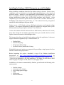
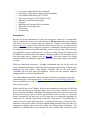
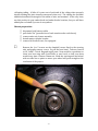
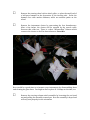
 Installing the Painless® #10102 Universal Street Rod Harness in early Fiat Spiders Bernie Seneway
June 1, 2009 Rev. C Acknowledgements Thanks to John Erskine at the Fiat Rescue League [email protected] for salvage parts, Rick Trawick at http://www.carsandplaces.com for his British automotive electrical assistance, Dennis Diehl at Painless Performance Products, and Brad Artigue http://www.artigue.com/?page_id=58 for his extensive Fiat wiring diagrams and for hosting this article. Errata Many Fiat Spiders manufactured by Pininfarina have wiring schematics, colors and codes different than described in factory service manuals. Please keep this in mind when wiring your car. Your input will help make this article more accurate and helpful to other Spider owners. Please contact me with any errors and omissions. © Bernard Seneway. All rights reserved. To add to your site, contact me at [email protected]
-1-
Installing the Painless #10102 Harness in an early Fiat Spider
Many reliability complaints about the Fiat Spider relate to electrics. Most of these complaints can be attributed to shoddy repairs/modifications at the hands of previous owners. However, even unmodified, well‐maintained early Spiders still have an outdated electrical system design and 30‐40 year‐old components. This wiring modification retains most of the OEM functions and controls. Upon completion, your electrical system will now operate like a modern American car; headlights work without the ignition key, etc. The reduced load on your ignition switch will add reliability in the years ahead. Subject car is a 1973 Spider with a 65A Bosch alternator and integral voltage regulator. The original equipment 42A Marelli alternator is marginal, and if yours has unsatisfactory output, replace with the 55 or 65A Bosch. I chose the Painless #10102 Universal Street Rod harness, which has 12 circuits, more than enough for the Spider, particularly when you consider that four of the Spider’s nine are devoted to the headlights alone. This harness does have a few deficiencies when used in this application. It does not support emission equipment, key or seatbelt buzzer, or: • Backup lights • Electric fuel pump • Oil pressure failure lamp • Hydraulic failure/handbrake On lamp Windshield wiper and washer are supported by providing a single power feed; no switch or motor wiring is provided. Before beginning the project, download a copy of the Painless installation instructions at http://www.painlessperformance.com/Manuals/10102.pdf to familiarize yourself with the procedure. Don’t be intimidated by Sections 7, 8 and 9 – they are not applicable to the Fiat installation. The items you will refer to most often are pages 1‐5, Figure 10‐7B, Table 11‐2, and pages 30‐31. In addition to the items recommended by Painless, you will need the following tools and materials: • Ratchet crimper • Automatic wire stripper • Low‐voltage power supply • VOM • Bulb grease • Brass toothbrush -2-
•
•
•
•
•
•
•
•
•
•
2 or 3‐pole, single‐throw switch (hazard) Double‐pole, triple‐throw toggle switch (headlight) 3 pcs. Radio Shack diode p/n 276‐1661 3 pcs. Tyco relay p/n V23234‐A1001‐X036 adhesive‐lined heat shrink tubing heat gun additional red, blue and yellow terminals additional 16 and 18 ga. wire wheel puller 24 mm socket Wiring Basics Because all of the terminations in your new wiring are crimp‐on, it is imperative that you employ the proper tools and techniques. Do not use a pliers‐type crimping tool; these can over‐ or under‐crimp the connector. Obtain a ratcheting crimper, such as this one. Look for red, blue and yellow dies on the tool; you will need all three. Make a few practice crimps on scrap wire to familiarize yourself with the tool. To crimp, squeeze the tool handles until they release and pop open. Only then have you applied the proper crimping force. To abort a crimp, release the handles with the small lever on the inside of the handle. Stripping modern TXL‐insulated wire is best performed with a stripper such as this one. You must remove the tough insulation without nicking the copper wire strands. Pliers‐type strippers should not be used. While not absolutely necessary, I strongly recommend that you fortify each and every termination and splice with adhesive‐lined heat shrink tubing, available from McMaster‐Carr and others. Part number 7861K53 will fit over butt splices, 74965K64 fits over blue and red terminals. Always use the smallest diameter tubing possible, to achieve the tightest fit. Use “fully insulated terminals”, where the plastic insulation completely covers the connection point, as shown here http://www.mcmaster.com/#catalog/114/0734
Use wire suitable for an oily and greasy environment. “Machine tool wire” from this same vendor is good. What’s with all the colors? Simple. Red‐colored terminals are used only on 20‐18 ga. Wire. Blue (all blue types; ring, butt, spade, etc.) for 16‐14 ga. Yellow for 12‐10 ga. Some very large terminals, including some shipped with your harness, are also red, but they are so large there can be no question what size wire they fit. Using the proper terminal for the wire size, in the proper die of a ratcheting crimping tool assures you of a perfect, long‐lasting connection. Want proof? Try pulling apart a connection you’ve made with scrap wire – if performed correctly, you won’t be able. Adhesive on the inside walls of the heat shrink tubing described here will melt at a temperature slightly below the point where the tubing begins shrinking. The adhesive is mechanically forced around the wire strands and terminal by the -3-
collapsing tubing. A little of it oozes out of each end of the tubing when properly shrunk, making the joint virtually waterproof when cool. The tubing also provides additional mechanical strength to the union of wire and terminal. At the very least, use this product in your under‐hood and under‐fender locations, but you will have added peace‐of‐mind if you use it everywhere. Chassis preparation □ disconnect both battery cables □ pull choke “On” (prevents loss of carb nuts down the carb throat) □ remove entire air cleaner assembly □ detach master cylinder bracket □ remove left footwell vent, if so equipped □
Remove the 4 or 5 screws on the clamshell covers fitted to the steering axle, and gently remove covers. Pry off the horn bezel. Tabs are located at 10, 2 and 7 o’clock. Bag and tag all parts. Now would be a good time to clean your horn ring with Scotch Brite or steel wool, so that your horn works every time. Remove 24mm nut. Mark the steering axle and wheel with a scribe line or paint to assure your wheel will point straight at the conclusion of the project. -4-
□
Remove the steering wheel with a wheel puller, or place the small end of a ball‐peen hammer in the depression of the steering axle. Strike the hammer face with another hammer, while an assistant yanks on the wheel. □
Remove the instrument cluster by unscrewing the four thumbscrews. After a few inches, the cluster will be stopped by the speedo cable. Unscrew this collar nut. There is a short “intermediate” harness which connects the cluster to the Fiat chassis harness. Save this. Now would be a good time to rejuvenate your instruments by disassembling them and cleaning the glass faces. You might as well replace all 14 lamps at this time, too. □
Remove the steering column switch assemble by loosening the one band nut and pulling the assembly toward you. Note the assembly is keyed and will only seat properly in one orientation. -5-
You now must decide if you wish to retain two failure‐prone factory items on your car; intermittent wipers and panel lamp dimmer. My car is a “fair weather” item, so I don’t need the former. I’ve also re‐lamped and cleaned my instruments, and without the dimmer, my cluster illumination is just right. These instructions assume you’re scrapping these two items. If you’re keeping them, adjust accordingly. Prepare the Painless Harness Unwrap the harness, and separate the three main bundles; engine, cockpit and tail. Notice the exceptional length of this harness. It fits full‐size American cars twice the size of your roadster. Resist the temptation to shorten any of the three bundles at this time. □
Remove BLU/WHT #902 1 from engine section, cut and cap near fuse block. (Capping wire neatly can be accomplished with a short section of heat shrink tubing – allow ¼ ‐ ½” of tubing to extend beyond the wire, then pinch it while hot.) □
□
□
□
□
Move ORN #917 and WHT #918 from the engine bundle and loosely associate it with cockpit bundle. Remove RED #954 from engine section, unless you’re already converted to an electric choke carb. Cap and coil under driver’s carpet for later use by you or the next owner. Go to Page 27 of the Painless manual. Draw a line thru the following wires; they are unused or not included in this kit: 902, 903, 910, 911, 912, 913, 942, 943, 944, 946, 947, 956, 957 and 958. Re‐label BLK/WHT #904 “fuel pump” if your car is equipped with an electric fuel pump. Join with tail section bundle. Cut and cap otherwise. Remove the Fiat fuse block, relays and all wiring. Do not discard or cut the Fiat intermediate cluster harness, or any of the wires on the instrument column switch assembly. Observe the hood release, emergency hood release and other items throughout the car which are not wires; don’t cut them! Save and reuse sender boots. 1
Colors are shown in their three-letter abbreviation. In the case of multi-color wires, the first color is the
body, the second is the stripe. All Painless wire numbers are three-digit beginning with the numeral “9”.
Any references to Fiat wiring in this article will follow the same color conventions.
-6-
□
Install your new fuse panel in the space vacated by the old. I shortened the two top mounting posts on the new panel, and bent slightly forward the metal dash flange to mount the Painless panel. ← cut here You may find it helpful to jack up the side of the car you’re working on; your back will thank you at the end of the day. Be sure to use jack stands, wheel chocks, and other appropriate safety measures. Don’t install the fragile turn signal and hazard flashers until the installation is complete. Note the damaged one in the photo above. □
Ground BLK #961 leading from the fuse block. Pass engine compartment bundle thru Fiat firewall grommet. It is the perfect size for the Painless harness. -7-
Add two 18 ga. wires to this bundle. Use two different colors. Label them with masking tape on each end “oil fail” on one wire and “brake fail” on the other. These wires must be long enough to reach from their respective senders to the instrument panel. Make sure you have plenty of slack. Create another bundle of wires for the windshield wiper and washer. Two wires for the washer, five for the wiper. They must reach from the wiper and washer motors, across the firewall, thru the grommet, and into the cluster area. You can cut the connector from the wiper factory wiring, or attach your bundle directly to the wiper motor. Label both ends of each wire as follows: Windshield Wiper/Washer Fiat Mine Function washer + washer ‐ GRY/BLK BLU #905 wiper B+ GRY wiper Lo BLU wiper Hi BLU/BLK Wiper park BLK wiper ground BLU/WHT ? (not used) Note in “Mine” column above the colors of the wires you’ve used for this bundle, so that you or the next owner can troubleshoot, if necessary. In this new configuration, wiper stalk “Up” is “Off”, first click down is “Lo” and second click (Bottom) position is “Hi”. □
Attach one 276‐1661 diode from Park to Lo, with the stripe facing “Lo”. Do this in the interior of the car, not under the cowl. -8-
Wiper Schematic Yes, BLU #905 does connect to both the wiper motor and stalk. Power is required at the motor to run the Park circuit to the bottom of the stroke. In the firewall trough with this bundle go the following: □ WHT #914 alternator exciter (to alternator FastOn connector) The instrument cluster charge lamp is spliced into this wire. See p. 15 □ RED #915 alternator (to alternator output post) □ GRN #921 water temperature sender □ PUR/WHT #923 tachometer source (to coil [‐]) □ PNK #920 coil [+] You need not fabricate and install “High Output Wire” described on Painless Page 7 and elsewhere. While routing the Painless bundles and your added wires, observe the hood release and emergency hood release. Don’t obstruct or hinder their operation. Route wiring around the left footwell vent, as shown. -9-
□
Modify handle on previously‐removed footwell vent to clear new panel. Do not re‐install vent at this time. Ignition Switch Wire the ignition switch as follows. The Fiat switch duplicates several terminals. Use any properly‐labeled terminal. Take care in routing this bundle from the fuse panel to the cluster area. Do not impede steering wheel movement or permit chafing of any wires. If you wish to install a starter safety switch, see next page. Ignition Switch Painless Fiat PNK #931 INT BRN #932 INT ORN #933 15/54 RED #934a 30/1 RED #934b 30 PUR #919 50 - 10 -
□
□
□
□
Cut and discard PNK and WHT key buzzer wiring. No need to cap the ends; they carry no voltage. Cut ‘em flush. Wire the starter and solenoid per the Painless manual. Don’t forget the Maxi Fuse. If your Spider is a 1972 or newer model, you can reuse the emissions switch on the clutch as a starter safety switch as in contemporary vehicles. Place this switch inline between the fuse panel and ignition key of PUR#919. The starter will not engage unless the clutch pedal is depressed. Install 3 relays in the space vacated by the OEM units. Label them “Lo” “Hi” and “Fan”. (The horn relay is incorporated into the new fuse panel.) Sockets make installation easier, but you lose the Painless wire color coding and nomenclature. Your choice. - 11 -
Connect relays as follows: Relay Pinout Pin Function Description 86 trigger #901, #908 or #909 “In”, depending on relay function 85 relay ground splice 3 leads together; connect to chassis ground 30 raw power in 87 relay out 87a from starter terminal ‐ splice 3 leads together; use excess #916 wire trimmed from solenoid installation to headlight Lo beam, Hi beam and Fan remove or insulate terminal, which is “hot” when lights, etc. are “Off”. May arc to ground otherwise. - 12 -
□
Complete Engine Section wiring to lights, horn, etc. The Painless kit contains new headlight sockets; use them. I routed the right side lighting in a bundle tie‐wrapped to the front valence. An alternate is to go rearward from the relays, across the firewall trough, and up the right side. Grounding Many Fiat electrical difficulties arise from faulty grounds. While you rewire your car, take care to provide adequate electrical grounds in multiple locations, visible to yourself and future owners. Inspect and repair, if necessary, the engine‐to‐body ground cable. Tail Section □
Add one 16 ga. and one 18 ga. wire to the tail section bundle. Label both ends “Lo Fuel” (18 ga.) and “Backup Lights” (16 ga.). Fuel wire should reach from cluster area to fuel tank; backup lamps are attached to a switch in the transmission. There are two transmission switches; one for emissions and one reverse switch. Consult a service manual for switch identification for your model year. PNK #939 fuel sender goes to the forward terminal on the tank. Your Lo Fuel wire goes to the rearward terminal. Both stop lamps are powered by ORN #950. Ensure a good electrical connection to individual lamps by brushing their terminals with a brass toothbrush. You might as well replace all these bulbs, too. Clean sockets thoroughly with sandpaper and brass toothbrush. Apply a film of lamp grease on both the bulb and socket, as well as terminals. Inspect and repair or replace, if necessary, the black ground harness on each tail lamp assembly. Headlight Switch This harness uses a double pole, triple‐throw (DP3T) switch. You cannot use the Fiat switch with this harness. I found it difficult to find an “OFF‐ON‐ON” configuration, but several manufacturers make an “ON‐ON‐ON” type. Simply don’t use the first set of contacts, and cap them off by pushing empty FastOn connectors onto them. You don’t need a monster switch here, as all the large headlight current is handled by relays. 5A @ 28VDC rating is sufficient. One terminal pair is active when parking lights are selected, and these terminals are maintained when the second pair (headlamps) is selected. Here is one switch source: http://shop.willyselectronics.com/browse.cfm/4,4898.html Use your VOM to determine the terminal locations and switch orientation. Remember that “Up” in Fiats is “Off”. Wire switch as follows: - 13 -
Headlight Switch Painless Function RED/BLK #928 input (bridge two terminals) input parking, tail lights
instrument lamps
head lights BRN #927, 929, 930 BLU/YEL #907 Instrument Panel Before beginning this final section, you must discern the color code for your car’s cluster and column switch assembly. Use a “wall wart” or similar low‐power DC power supply and VOM to fill in the table below. Do this in a clean, well‐lit area, seated comfortably … not squatting on the garage floor! Test car’s info is shown for reference, but you must perform this step on yours, too. Cross out the Test Car info when finished, so you don’t use this data by mistake. Take your time; errors here can take many hours to troubleshoot and correct. Wiper/Washer Switch Test Car Function Painless My Car BLU washer + BLU #905 BRN washer ‐ not provided YEL/BLK wiper common BLU #905 RED wiper Lo not provided GRY wiper Hi not provided - 14 -
Instrument Cluster Test Car Function Painless My Car GRY/YEL oil sender Lt. BLU/BLK #922 GRY oil fail none (add) BLU/BLK charge lamp PUR/BLK charge lamp WHT/PNK inst. lighting BRN# 930 YEL/RED lights on BRN #930 BLU/WHT turn indicator see p.17 WHT/BLK inst. ground BLK #961 YEL/BLK inst. power ORN/BLK #955 GRY/RED low fuel none (add) BLU/YEL fuel sender PNK #939 GRN/WHT water sender Lt. GRN #921 GRY/WHT tach sender PUR/WHT # 923 insert the charge lamp in series with WHT #914 (see below) Charge Lamp Circuit WHT #914
WHT #914
Charge
Alternator
Fuse Panel
Lamp
When the ignition key is “On” and the alternator is not charging, current flows from the fuse panel to the excitor terminal on the alternator, which is grounded in this state. The charge lamp illuminates. When the alternator has sufficient output, the voltages present at the fuse panel and alternator are nearly equal, so no current flows thru the lamp. If the Charge Lamp bulb is missing or defective, the circuit is broken and the alternator will not charge, nor will you have any indication of this malfunction. Observe the charge lamp during your daily startup procedure.
- 15 -
Headlight Dimmer Switch Test Car Function Painless My Car BLU + GRY/RED B+ BLU/YEL #907 GRN 2
Lo beam 3
TAN #909 GRN2
Hi beam Lt. GRN #908 Splice the intermediate harness to the Painless cluster wires. Before cutting any wires, plug in the intermediate harness to the instruments to avoid cutting the wrong end! Notice the wiring colors often change from the intermediate harness to individual instruments. Label with Painless numbers the freshly‐cut intermediate harness wires. Then detach from the cluster and wire the car. You will find that there are significantly fewer wires with your new installation, plus these wires are smaller diameter and much more flexible than those you’ve removed. This will allow you to provide a little more slack to this assembly, making subsequent relamping a lot easier. Cut and cap unused wires from the column switch assembly and intermediate harness. 2
3
same color; different circuits. Note: this harness does not support “flash to pass” momentary Hi beam
stalk “up” for Lo beam, “down” for Hi beam headlight
- 16 -
Turn Signal Indicator Your Fiat uses one indicator serving both right and left lamp sets. Wire this indicator as follows: Hazard Switch The factory hazard switch cannot be used. You must obtain a 2‐ or 3‐pole single‐
throw switch. The switch can have internal 12 VDC illumination, if you wish. This illumination source would connect to BRN #930. Pick a 2‐pole switch if you don’t require a separate hazard warning indicator (the turn signal indicator will flash with hazard ON). For external indication like the factory wiring, use a 3‐pole switch with the third pole to Indicator 59 (right‐side location) on the panel. Wire per diagram below. - 17 -
I used a non‐illuminated 2‐pole DPST rocker switch epoxied into the Fiat bezel, then filled with body filler and painted texture black. This is a popular switch with 22 x 27mm body and 22 x 30mm cutout. - 18 -
- 19 -
Brake Switch □
Wire ORN #917 and WHT #918 to the two terminals on the brake switch. Route and secure wires to avoid interference with the steering wheel or pedals. Radio If your car has a radio, wired RED #940 to B+ unswitched (constant) to the appropriate wire on your radio to maintain clock, station presets, etc. RED/BLK #941 is B+ switched. Either of these can also be used to power your cigarette lighter, depending on whether you want constant or switched power to this outlet. Horn The Spider horn contacts have polarity. Examine the steering column switch assembly. The contact nub closest to the axle is (+), which goes to BLK #953, the other (‐). Accessories Wire the heater fan, courtesy lamp and other accessories to ORN/BLK #955. Testing Power your car only from the battery charger while you test individual circuits, per the Painless manual. Pull the “Coil” fuse from the block so as to avoid burning the ignition points during prolonged testing. The area of greatest uncertainty is the cluster, so leave it out of its nacelle, and clamshell covers off while you test wipers, lights, etc. Don’t forget to reattach the speedo cable before securing the cluster. When reinstalling the column switch assemby, slide the assembly toward you so that the turn signal defeat pin mates with the hole in the steering wheel slip ring. Save these instructions for future reference and future owners. - 20 -