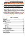
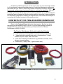
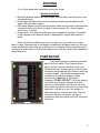
1
Wire Harness Installation Instructions Manual #90565 For Installing: #10144 Customizable Extreme Off-Road Harness 15 Circuit Perfect Performance Products, LLC Painless Performance Products Division 2501 Ludelle Street Fort Worth, TX 76105-1036 800-423-9696 phone – 817-244-4024 fax Web Site: www.painlessperformance.com E-Mail: [email protected] If you have any questions concerning the installation of this harness or having trouble in general, feel free to call Painless Performance Products' tech line at 1-800-423-9696. Calls are answered from 8am to 5pm central time, Monday thru Friday, except holidays. We have attempted to provide you with as accurate instructions as possible, and are always concerned about corrections or improvements that can be made. If you have found any errors or omissions, or if you simply have comments or suggestions concerning these instructions, please write us at the address above. Or, better yet, send us a fax at (817) 244-4024 or e-mail us at [email protected]. We sincerely appreciate your business. Perfect Performance Products, LLC shall in no event be liable in contract or tort (including negligence) for special, indirect, incidental, or consequential damages, such as but not limited to, loss of property damage, or any other damages, costs or expenses which might be claimed as the result of the use or failure of the goods sold hereby, except only the cost of repair or replacement. 90565 Installation Manual January 14, 2014 Copyright 2008 by Perfect Performance Products, LLC 2 CAUTION: BEFORE THE REMOVAL OF YOUR ORIGINAL HARNESS AND/OR THE INSTALL OF YOUR NEW PAINLESS HARNESS, DISCONNECT THE POWER FROM YOUR VEHICLE BY REMOVING THE NEGATIVE OR POSITIVE BATTERY CABLE FROM THE BATTERY.THE BATTERY IS NOT TO BE CONNECTED UNTILL THE PAINLESS HARNESS HAS BEEN INSTALLED AND TESTED. A full color copy of these instructions can be found at http://www.painlessperformance.com/InfoSearch/manuals.php Painless Performance Products recommends you, the installer, read this installation manual from front to back before installing this harness. Due to the variables involved with your particular installation, reading this manual will give you considerable insight on the proper installation of this harness. In the event that there are unused or unconnected wires, the ends of all unused wires will need to be terminated with an insulated terminal or taped. Doing so will prevent the wires from shorting and causing harness failure or fire. TABLE OF CONTENTS INTRODUCTION ….……………………………………………..……..……..……….. SMALL PARTS………………………………………………………………….……… TOOLS NEEDED……………………………………………………….……..……….. FUSE BLOCK MOUNTING…………………………………………..……..………… MAXI FUSE…………………………..…….…………………………..……..………… ROUTING……………………………………………………………..……..………..… ROUTING GUIDELINES............................................................................. FUSEBLOCK…………………………………………..……..………………………… FUSE INPUTS………………………………………………………………….. FUSE OUTPUTS……………………………………………………………….. RELAYS………………………………………………………………………….. RELAY INPUTS……………………………………………………………..….. RELAY 12V……………………………………………………………….….….. RELAY GROUNDS…………………………………………………………….. RELAY OUPUTS……………………………………………………………….. RELAY ACTIVATION METHODS…………………………..……………………….. 12V ACTIVATION………………………………………………………………. GROUND ACTIVATION……………………………………………………….. CIRCUIT BREAKERS & JUNCTION BLOCK………………………………..…….. CHARGING………………………………………………….………………………….. TESTING THE SYSTEM………….………………………………………………..….. FUSE BLOCK TEMPLATE………………………………………………………..….. 5 6 6 6 8 9 9 9 10 11 11 12 12 13 13 14 14 15 15 16 18 21 3 Figures CONTENTS……………………………………………………………………………… FUSE BLOCK IN MOUNTING BRACKET………………………………………….. FUSE BLOCK COVER………………………………………………………………… FUSE BLOCK MOUNTED…………………………………………………………….. 5 7 7 8 ILLUSTRATIONS FUSE BLOCK ………………………………………………………………………….. 9 FUSE INPUTS………………………………………………………………………….. 10 CREATING SWITCHED 12V………………………………………………………….. 10 FUSE OUTPUTS……………………………………………………………………….. 11 RELAY INPUTS……………………………………………………………………..….. 12 RELAY 12V……………………………………………………………………..……….. 12 RELAY GROUNDS…….……………………………………………………………….. 13 RELAY OUTPUTS…………………………………………………………………..….. 13 12V ACTIVATION OF RELAY(S) …………………………………………………….. 14 GROUND ACTIVATION OF RELAY(S) ……………………………….…………….. 14 CIRCUIT BREAKERS & JUNCTION BLOCK……………………………………….. 15 DELCO ALTERNATOR………………..……………………………………………….. 16 CS-130 ALTERNATOR……………..………………………………………………….. 17 CS-130D ALTERNATOR……………..……………………………………………….. 17 3G ALTERNATOR……………..……………………………………………………….. 17 TESTING THE SYSTEM………….………………………………………………..….. 18 FUSE BLOCK TEMPLATE………..………………………………………………….. 21 4 INTRODUCTION The Extreme Off-Road Harness can be used to wire any non-street legal vehicle. Its 10 circuits and 4 relays will provide power to all critical and accessory components associated with your vehicle. Unlike other chassis harnesses provided by Painless, this harness only contains power Inputs and Outputs to and from the fuse block. With this harness fitting such a wide range of vehicles, these instructions will be general installation procedures. Referring to a factory wiring schematic of your vehicle will aid in connecting factory charging and ignition systems and/or connecting to factory switches. For aftermarket components, following the manufacturer’s instructions will be helpful in connecting the Painless harness to their specific product. CONTENTS OF THE PAINLESS WIRE HARNESS KIT Refer to the Contents Figure (below) to take inventory. See that you have everything you’re intended to have in this kit. If you find that anything is missing or damaged, please contact the dealer where you obtained the kit or Painless Performance at (800) 423-9696. The Painless Wire Harness Kit should contain the following: Wire Harness, with Fuse Block and relays installed 1 small parts bag containing Maxi Fuse components and terminals 1 large parts bag containing heat shrink, a junction block, 3 circuit breakers, zip ties, relays, and a fuse label 1 parts box containing miscellaneous ring terminals, terminals, fuses, screws, nuts and washers. 2 rolled wires (1 charge wire, 1 ignition switch wire) CONTENT FIGURE- All of the parts in the Painless kit 5 SMALL PARTS The bagged parts, as well as the parts box, should provide you with everything you need in order to properly install the Painless Extreme Off-Road Harness. The smaller bag containing the large Maxi Fuse contains all the necessary parts to properly install an in-line fuse between the Alternator and the vehicle’s Battery. The ring terminals found in this bag will cover a wide range of wire diameters to help connect all wires your individual installation may require to be connected to the Maxi Fuse. For additional information on the Maxi Fuse and proper installation refer to page 8. The larger bag contains circuit breakers for the relays, spare relays, and a junction block to allow power distribution from the battery and maxi fuse to the fuse block and circuit breakers. This bag also contains a fuse label for fuse identification, zip ties, a rubber alternator boot, and heat shrink. The parts box contains an assortment of fuses and terminals. Mounting hardware for the junction block and circuit breakers are also located in the parts box. TOOLS NEEDED In addition to your regular hand tools, you will need, at least, the following tools: Crimping Tools* Wire Stripper Test Light or Volt Meter Small (10 amp or less) Battery Charger** *We recommend that you use a quality crimper to avoid over crimping. ** see TESTING THE SYSTEM located on page 18. FUSE BLOCK MOUNTING Fuse Block mounting begins by locating all the necessary parts in the Painless kit needed for proper Fuse Block Mounting. These parts are: Fuse Block Mounting Bracket 4 Large Philips Head Screws 2 of the ½” Self Tapping Screws Begin by finding a suitable location to mount the fuse block. The location of the Fuse Block must be easy to access, yet out of the way during operation of the vehicle. Suitable locations for the fuse block can generally be found under the dash or on the firewall. The Fuse Block supplied with the Extreme Off-Road harness has a weather proof seal; however, avoid mounting the Fuse Block where it may become in direct constant 6 contact with water or in a position which could be submerged in water during operation of the vehicle. Begin by installing the Fuse Block onto the Mounting bracket. The Fuse Block will slide into the bracket causing the legs to “wrap” around the Fuse block. Refer to the photo below and on the next page. Using the 4 Philips head screws, mount the fuse block to the mounting bracket. The Fuse Block cover can be mounted to the bracket by utilizing one of the Fuse Block Mounting Holes. Some my find it easier to cut the tab from the fuse block cover altogether to allow more room when the cover is removed. Note: Applying a small amount of a silicone based lubricant on the red seal of the Fuse Block will aid in getting the cover off at a later time after installation. If you do not wish to use the mounting bracket, and would like to do a through panel fuse block installation, a template has been provided for you on page 20. 7 Using 2 of the ½” self tapping screws and the holes pre-drilled at the top of the Fuse Block mounting bracket secure the bracket to the vehicle. MAXI FUSE CAUTION: DISCONNECT THE POWER FROM YOUR VEHICLE BY REMOVING THE NEGATIVE OR POSITIVE BATTERY CABLE FROM THE BATTERY. THE BATTERY IS NOT TO BE CONNECTED UNTILL THE PAINLESS HARNESS HAS BEEN INSTALLED AND TESTED. Begin by locating the MAXI FUSE component bag in the parts kit. These components are: a MAXI FUSE Base & Cover, a self-tapping mounting screw, the 100 AMP MAXI FUSE, and several different size ring terminals. Using the mounting screw, mount the fuse base as close to the battery, or battery power source, as possible. This power source can be the Battery itself or the B+ at the Starter Solenoid. Actual connections made to the Maxi Fuse will differ according to your specific application requirements; refer to the CIRCUIT BREAKERS AND JUNCTION BLOCK illustration, page 16, for the proper connection of the Maxi Fuse. Install the MAXI FUSE into the BASE, and the COVER over the MAXI FUSE assembly. Before doing so, make certain that the Positive or Negative Battery Cable is not connected. Harness failure will result. 8 ROUTING Try to follow these basic guidelines during your install. Routing Guidelines Route the harness away from sharp edges, exhaust pipes, and hood, door, and windshield hinges. Inside edges provide protection from hazards and also provide places for tie wraps, clips and other support. Plan where harness supports will be located. Allow enough slack at places where movement could occur (body to frame, frame to engine, etc.). Use a support about every 12 inches. At wire ends, don’t depend on the terminals to support the harness. The weight of the harness could cause terminals to disconnect or copper wire strands to break. Wires should be bundled into groups. Use nylon ties, poly split loom, Power Braid, or tape. Exposed wires of the engine compartment and wires running to the rear of the vehicle may need some sort of wiring loom or covering. This is especially true for vehicles that spend time on off-road trails and/or have their four wheel drive capabilities tested frequently. FUSE BLOCK The following section contains information about the Fuse Inputs, Fuse Outputs, Relay wiring, and the color coordination found on the Painless Harness. All wires going to and from the fuse block are printed with their function and Fuse or Relay number. The printed descriptions are indicated in the text and images of these instructions as bold and in “quotations” (example: “FUSE 6 OUTPUT”). With this being a “universal” style harness and with an infinite amount of configurations this harness can wire, there will be no specific instructions on connecting each wire. It will be up to you, the installer, to determine were to connect each wire. The only instruction Painless can give is the type of connection each wire needs and/or the function of each wire. 9 Fuse Inputs The Fuse Input wires are solid color wires and are color coded to the Fuse Output wires. The 3 Fuse input wires are: PINK- ”FUSE 1-3 INPUT” ORANGE- “FUSE 4-6 INPUT” RED- “FUSE 7-10 INPUT” The power source these Input wires are connected to will determine if the Fuse Outputs will be switched 12v or battery constant. The splicing to connect each Fuse Input to the Fuse Block, seen to the left, comes pre-installed. The illustration below shows how to create switched 12 volt power. The drawing shows all wires associated with Fuses 7-10. Fuses 1-3 and/or Fuses 4-6 could also be used in this manner if more or less switched 12 volt sources are required with your application. The illustration also does not show the use of the junction block, refer to the CIRCUIT BREAKERS and JUNCTION BLOCK drawing on page 16. The “BATTERY B+ TO IGNITION SWITCH” wire seen in the illustration has been provided with the Painless kit. 10 Fuse Outputs The Fuse Output wires are all striped wires with the main color of the wire corresponding to the color found on the Fuse Input wire. The 10 Fuse Output wires are: PINK/BLACK- “FUSE 1 B+” PINK/WHITE- “FUSE 2 B+” PINK-RED- “FUSE 3 B+” ORANGE/BLACK- “FUSE 4 B+” ORANGE/WHITE- “FUSE 5 B+” ORANGE/YELLOW- “FUSE 6 B+” RED/BLACK- “FUSE 7 B+” RED/GREEN- “FUSE 8 B+” RED/WHITE- “FUSE 9 B+” RED-YELLOW- “FUSE 10 B+” The power source a Output wire carries is determined by the power source the Fuse Input is connected to. These Output wires will connect to components needing a power source. All Output wires are 14 and 16 gauge wires. The larger 14 gauge wire will handle up to 30 Amps, although it is not recommended to run more than two or three components with that high of amperage through the fuse block. The 16 gauge wire will handle up to 20 amps. An assortment of fuses has been provided to allow you to match each circuit’s amperage rating to the component being wired. Relays The 2 large 40 AMP Relays (Relays 1 & 4) and the 2 smaller 20 AMP Relays (Relays 2 & 3) found on the Fuse Block are each color coded based on the main color of the wires coming from each Relay. Relay 1 (next to Fuses 1-3)- Yellow Relay 2 (next to Fuses 4&5) - Blue Relay 3 (next to Fuses 6&7)- Green Relay 4 (next to Fuses 8-10)- White The stripes found on the wires coming from the Relays help indicate their function. However, like mentioned before, these wires are also printed with their function. 11 Relay Inputs The Relay Inputs are solid color wires like the Fuse Inputs. Also, like the Fuse Inputs, the color of the Relay Input wire determines the main color for the wires of the relay. The Relay Inputs are as followed: Yellow- “RELAY 1 INPUT” Blue- “RELAY 2 INPUT” Green- “RELAY 3 INPUT” White- “RELAY 4 INPUT” These Input wires will be connected to the Circuit breakers found in the parts bag. More on the Relay Input connections on page 16. Relay 12 Volt The Relay 12 volt wires are White striped wires, with the exception of relay 4 which has a Blue stripe. The Relay 12 Volt wires are: Yellow/ White- “RELAY 1 12 VOLT” Blue/ White- “RELAY 2 12 VOLT” Green/ White- “RELAY 3 12 VOLT” White/ Blue- “RELAY 4 12 VOLT” The Relay 12 Volt wires provide a power source to the electromagnetic coil inside the relays which switch, or activate, the relay. The 12 volt wire will be connected to either a battery constant 12 volt source or to a switched 12 volt source. The power source a 12 volt wire from the relay connects to will depend on the activation method of the relay. To determine the activation method that best suits your needs, see pages 14 & 15. 12 Relay Grounds The Relay Ground wires are Black striped wires. The Relay Ground wires are: Yellow/ Black- “RELAY 1 GROUND” Blue/ Black - “RELAY 2 GROUND” Green/ Black - “RELAY 3 GROUND” White/ Black - “RELAY 4 GROUND” The Relay ground wires provide a chassis ground source to the electromagnetic coil inside the relay which is used to switch, or activate, the relay. The Relay ground wire will connect to a good clean chassis ground or the negative side of the battery. Like the Relay 12 Volt wire, the connection of this ground depends on the activation method of the relay. To determine the activation method that best suits your needs, see pages 14 & 15. Relay Outputs The Relay Output wires are Red striped wires. The Relay Output wires are: Yellow/ Red- “RELAY 1 OUTPUT” Blue/ Red - “RELAY 2 OUTPUT” Green/ Red - “RELAY 3 OUTPUT” White/ Red - “RELAY 4 OUTPUT” The Relay Output wires carry power from the relay to the component needing power. Examples of components needing to be wired through a relay are: electric cooling fan(s), electric fuel pump, electric water pump, off-road/driving/fog lights. Anything that requires an amperage draw of 25 amps or more is generally better off wired through relays. This prevents high amperage draws through the main fuse block. 13 RELAY ACTIVATION METHODS 12 VOLT ACTIVATED RELAY A 12 volt activated relay is constantly grounded and will only send power out of the output side of the relay when 12 volts is applied to the relay, as the name implies. The 12 volt source can be wired directly to the relay or interrupted by a switch, as shown in the 12 VOLT SOURCE ACTIVATION drawing. Wiring directly to the relay would be used in the case of wiring a Fuel Pump relay or any other high amperage component you would want to run continuously while the key is in the on position. In these cases, make certain the 12 volt wire you are using is a Switched 12 volt wire and not a battery constant. The 12 volt activation wire can also be wired to a switch to offer the user OFF/ON capabilities. These are the situations a battery constant power source could be used. This would allow a component to be turned OFF or ON without the key in the ON position. However, unless a lighted switch is being used, a ground activated relay may work better to avoid running power through the switch. In the event that a switch is being used, make sure the amperage of the 12 volt source does not exceed the capabilities of the switch. 14 GROUND ACTIVATED RELAY A ground activated relay is just the opposite of the 12 volt activated relay, 12 volts (battery constant or switched) is supplied uninterrupted and the ground wire is switched. An example of this method is a thermostat operated fan relay. In this case however, a thermostatic switch would replace the switch in the drawing below. Like mentioned before, the ground activation method is best used when a component is operated by an unlit switch from the interior of the vehicle. CIRCUIT BREAKERS & JUNCTION BLCOK Three 40 amp Circuit Breakers have been provided to connect power to Relays. Each 40 amp relay will be wired to its own circuit breaker, while the two 20 amp relays will share a 40 amp circuit breaker. The Junction Block will be used to distribute battery power to the fuse block and to the circuit breakers. This will help from having too many wires connected to the Maxi Fuse or from having to make splices to high amperage feed wires. 15 CHARGING SYSTEMS Being a “universal” style harness and with so many different charging systems from different auto manufacturers, Painless has only supplied the Output charge wire. This wire will be the larger rolled Red 6 gauge wire provided with the harness. This wire is printed “ALTERNATOR B+ TO BATTERY B+”. This wire will need to be connected to the B+ lug of the Alternator, by first installing the rubber boot and then crimping on the appropriate ring terminal. Additional battery power and switched 12 volt wires will need to be supplied by you, the installer. A factory diagram of the charging system you are using will be needed in order to identify addition connections that may be needed to the Alternator and/or Voltage regulator. Some common charging system diagrams have been provided for you. 16 17 TESTING THE SYSTEM Use a small (10 amp or less) battery charger to power up the vehicle for the first time to test the circuits. If there is a problem anywhere, the battery charger's low amperage and internal circuit breaker will provide circuit protection. Make sure the Negative Battery cable is connected to the frame or engine, and make sure there is a ground between the engine and frame, as well as the frame and the body. The Negative Battery cable should still be disconnected from the Battery. Connect the Battery Positive cable to the Positive side of the Battery and also make sure this cable is connected to the B+ side of the Starter Solenoid and is connected. Connect the Battery Charger's NEGATIVE cable to the automobile chassis, engine block or to the disconnected Negative Battery cable. Do NOT connect the Battery Charger's NEGATIVE cable to the Battery. Connect the Battery Charger's POSITIVE cable to the automobile's positive battery terminal lug. INDIVIDUALLY turn on each light, ignition, wiper circuit, etc. and check for proper operation. After all circuits have been checked, disconnect the battery charger and attach the vehicles battery cables to the battery. 18 NOTES 19 20 Painless Performance Limited Warranty and Return Policy Chassis harnesses, fuel injection harnesses and Striker ColdShot are covered under a lifetime warranty. All other products manufactured and/or sold by Painless Performance are warranted to the original purchaser to be free from defects in material and workmanship under normal use. Painless Performance will repair or replace defective products without charge during the first 12 months from the purchase date. No products will be considered for warranty without a copy of the purchase receipt showing the sellers name, address, and date of purchase. You must return the product to the dealer you purchased it from to initiate warranty procedures. Copyright 2008 by Perfect Performance Products, LLC FUSE BLOCK TEMPLATE FUSE BLOCK TEMPLATE If for some reason you do not want to use the mounting bracket included with the kit, above is a template of the main fuse block. The template can be used in a through panel mount situation, such as a firewall .Some distortion to the template image may take place due to the mass printing of this manual; these distortions will be less than 1/16” of an inch. Slight trimming may be needed once all holes, indicated by the shaded areas, have been cut because of this distortion. To avoid possible trimming, screw hole sizes could be enlarged to ¼” and cuts could be made 1/16” outside of the shaded area. 21