1
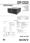
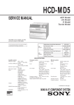
CDP-CX200
SERVICE MANUAL
US Model
Canadian Model
AEP Model
UK Model
E Model
Australian Model
PX Model
Model Name Using Similar Mechanism
NEW
CD Mechanism Type
CDM-40
Base Unit Type
KSM-213BKN/M-N
Optical Pick-up Type
KSS-213B/S-N
SPECIFICATIONS
USA, Canada
120V AC, 60Hz
Europe and Singapore
220V - 230V AC, 50Hz
E, PX
Australia
240V AC, 50Hz
COMPACT DISC PLAYER
MICROFILM
—1—
MODEL IDENTIFICATION
— BACK PANEL —
TABLE OF CONTENTS
1. SERVICING NOTE ........................................................... 3
2. GENERAL .................................................................... 4
3. DISASSEMBLY
3-1.
3-2.
3-3.
3-4.
3-5.
Front Panel Assembly ......................................................... 9
Back Panel Assembly ......................................................... 9
Table Assembly ................................................................ 10
Mechanism Deck Assembly ............................................. 10
Base Unit Assembly ......................................................... 11
4-982-790-
US Model
Canadian Model
AEP,German Model
UK Model
E,PX Model
Singapore Model
Austrarian Model
4. TEST MODE ............................................................... 12
5. ADJUSTMENTS
5-1. Mechanical Adjsument ..................................................... 13
5-2. Electrical Block Checking ................................................ 19
: 0π
: 1π
: 2π
: 3π
: 4π
: 5π
: 6π
6. DIAGRAMS
CAUTION
6-1. Circuit Boards Location ................................................... 21
6-2. IC Pin Function
• IC101 Digital Servo, Digital Signal Processor
(CXD2545Q) ................................................................ 22
• IC303 System Control (CXP84332-Q28Q) ................. 25
6-3. Block Diagram ................................................................. 27
6-4. Printed Wiring Board — BD, DISP Section — ............... 31
6-5. Schematic Diagram — BD, DISP Section — .................. 35
6-6. Printed Wiring Board — MAIN Section — ..................... 39
6-7. Schematic Diagram — MAIN Section — ........................ 43
6-8. IC Block Diagrams ........................................................... 47
Use of controls or adjustments or performance of procedures
other than those specified herein may result in hazardous radiation exposure.
The laser component in this product
is capable of emitting radiation
exceeding the limit for Class 1.
This appliance is classified as
a CLASS 1 LASER product.
The CLASS 1 LASER
PRODUCT MARKING is
located on the rear exterior.
7. EXPLODED VIEWS
7-1.
7-2.
7-3.
7-4.
7-5.
7-6.
7-7.
Case and Back Panel Section ........................................... 50
Disc Table Section ............................................................ 51
Front Panel Section .......................................................... 52
Mechanism Section-1 (CDM-40) ..................................... 53
Mechanism Section-2 (CDM-40) ..................................... 54
Base Unit Section-1 (KSM-213BKN/M-N) ..................... 55
Base Unit Section-2 (KSM-213BKN/M-N) ..................... 56
This caution label
is located inside
the unit.
8. ELECTRICAL PARTS LIST ........................................ 57
Notes on chip component replacement
• Never reuse a disconnected chip component.
• Notice that the minus side of a tantalum capacitor may be
damaged by heat.
Flexible Circuit Board Repairing
• Keep the temperature of soldering iron around 270˚C
during repairing.
• Do not touch the soldering iron on the same conductor of the
circuit board (within 3 times).
• Be careful not to apply force on the conductor when soldering
or unsoldering.
—2—
SECTION 1
SERVICING NOTE
SAFETY CHECK-OUT
(US model only)
NOTES ON HANDLING THE OPTICAL PICK-UP BLOCK
OR BASE UNIT
After correcting the original service problem, perform the following safety checks before releasing the set to the customer:
Check the antenna terminals, metal trim, “metallized” knobs, screws,
and all other exposed metal parts for AC leakage. Check leakage as
described below.
The laser diode in the optical pick-up block may suffer electrostatic
breakdown because of the potential difference generated by the
charged electrostatic load, etc. on clothing and the human body.
During repair, pay attention to electrostatic breakdown and also use
the procedure in the printed matter which is included in the repair
parts.
The flexible board is easily damaged and should be handled with
care.
LEAKAGE
The AC leakage from any exposed metal part to earth Ground and
from all exposed metal parts to any exposed metal part having a
return to chassis, must not exceed 0.5 mA (500 microampers). Leakage current can be measured by any one of three methods.
1. A commercial leakage tester, such as the Simpson 229 or RCA
WT-540A. Follow the manufacturers’ instructions to use these
instruments.
2. A battery-operated AC milliammeter. The Data Precision 245
digital multimeter is suitable for this job.
3. Measuring the voltage drop across a resistor by means of a VOM
or battery-operated AC voltmeter. The “limit” indication is 0.75
V, so analog meters must have an accurate low-voltage scale.
The Simpson 250 and Sanwa SH-63Trd are examples of a passive VOM that is suitable. Nearly all battery operated digital
multimeters that have a 2V AC range are suitable. (See Fig. A)
NOTES ON LASER DIODE EMISSION CHECK
The laser beam on this model is concentrated so as to be focused on
the disc reflective surface by the objective lens in the optical pick-up
block. Therefore, when checking the laser diode emission, observe
from more than 30 cm away from the objective lens.
LASER DIODE AND FOCUS SEARCH OPERATION CHECK
Carry out the “S curve check” in “CD section adjustment” and check
that the S curve waveform is output repeatedly.
To Exposed Metal
Parts on Set
0.15µF
1.5kΩ
AC
voltmeter
(0.75V)
Earth Ground
Fig. A. Using an AC voltmeter to check AC leakage.
SAFETY-RELATED COMPONENT WARNING !!
COMPONENTS IDENTIFIED BY MARK ! OR DOTTED LINE
WITH MARK ! ON THE SCHEMATIC DIAGRAMS AND IN
THE PARTS LIST ARE CRITICAL TO SAFE OPERATION.
REPLACE THESE COMPONENTS WITH SONY PARTS
WHOSE PART NUMBERS APPEAR AS SHOWN IN THIS
MANUAL OR IN SUPPLEMENTS PUBLISHED BY SONY.
ATTENTION AU COMPOSANT AYANT RAPPORT
À LA SÉCURITÉ!!
LES COMPOSANTS IDENTIFIÉS PAR UNE MARQUE ! SUR
LES DIAGRAMMES SCHÉMATIQUES ET LA LISTE DES
PIÈCES SONT CRITIQUES POUR LA SÉCURITÉ DE
FONCTIONNEMENT. NE REMPLACER CES COMPOSANTS
QUE PAR DES PIÈCES SONY DONT LES NUMÉROS
SONT DONNÉS DANS CE MANUEL OU DANS LES
SUPPLÉMENTS PUBLIÉS PAR SONY.
—3—
SECTION 2
GENERAL
LOCATION OF PARTS AND CONTROLS
Front Panel
1 23456
8
7
!•
1
2
3
4
5
6
7
8
9
!º
POWER button
CONTINUE button
Display window
SHUFFLE button
PROGRAM button
REPEAT button
Front cover
Remote sensor
JOG dial
ENTER button
9
!º !¡!™
!¶!§ !∞ !¢ !£
!¡
!™
!£
!¢
!∞
!§
!¶
!•
CHECK button
CLEAR button
p (stop) button
P (pause) button
· (play) button
≠ AMS* ± button
OPEN button
BLOCK 1-8 buttons
* AMS is the abbreviation for Automatic Music Sensor.
—4—
PX
This section is extracted from
instruction manual.
—5—
—6—
—7—
—8—
SECTION 3
DISASSEMBLY
Note : Follow the disassembly procedure in the numerical order given.
3-1. FRONT PANEL ASSEMBLY
6 Remove the claw
1 Two screws
(BVTP 3x8)
7 Front panel assembly
5 Remove the claw
3 Two screws (BVTT 3x6)
4 Flat type wire (CN601)
2 Three screws (BVTT 3x6)
3-2. BACK PANEL ASSEMBLY
1 Connector
(CN501)
5 Remove the PC board holder
6 Back panel
2 Four screws (BVTT 3x6)
4 Screw
(BVTP3x10)
3 Five screws
(BVTT3x6)
—9—
3-3. TABLE ASSEMBLY
4 Three screws (BVTT3x6)
1 Stop ring (E type)
5 Three holder assemblies
6 Table assembly
7 Washer
2 Two screws
(BVTT3x6)
3 Two holder assemblies
3-4. MECHANISM DECK ASSEMBLY
!º Mechanism deck
6 Flat type wire
(23core) (CN303)
Main board
1 Four screws (BVTT3x6)
Jack board
Main board
2 Screw
(BVTT3x6)
4 Connector
(CN308)
7 Connector
(CN304)
Jack
board
8 Connector (CN504)
3 Connector
(CN303)
Illumination
board
5 Guide
assembly
9 Nine screws (BVTT3x8)
— 10 —
3-5. BASE UNIT ASSEMBLY
1 Screw (BVTT3x6)
2 Fulcrum plate
(BU UPPER) assy
3 Base unit
— 11 —
SECTION 4
TEST MODE
4-1. Display Check Mode
4-3. Key and Display Check Mode
With the power turned off (standby state), press the POWER button
while pressing the P (pause) button.
All FL segments and grids light up together with the · (play), P
(pause), and standby LEDs.
At the same time, the GROUP LEDs are scanned one by one.
To set this mode, connect the test point (TP302:AFADJ) on the MAIN
board to Ground, and turn on the power supply plug to the outlet.
Note: To exit this mode, press the POWER button.
• All FL segments and grids will light up. (All lit check)
When a button is pressed, the types of buttons pressed until then
will be displayed on the left side and the number of the buttons will
be displayed on the right side. However, these will not be displayed
for the following special buttons.
4-2. ADJ Mode
1. Turn ON the power of the unit, set disc to disc table, and perform
chucking.
2. Disconnect the power supply plug from the outlet.
3. To set ADJ mode, connect the test point (TP301:ADJ) of the MAIN
board to Ground, and turn on the power supply plug to the outlet.
The power will turn on automatically, and the first track will be played.
In this mode, table rotation and loading operations are not performed
because it is taken that the disc has already been chucked.
p(stop) button:
FL segment check
(Refer to FL Tube Check Patterns)
P(pause) button: FL grid check (Refer to FL Tube Check Patterns)
The pause LED also lights up simultaneously.
·(play) button: All FL segment and grid will light up
The play LED also lights up simultaneously.
FL Tube Check Patterns
Segment check
Note: The same operations are also performed in the following when
the test point (TP301:ADJ) is connected to Ground after turning on the power.
• Direct search (movement of sledding motor) is not performed during accessing
• Ignored even when GFS becomes L
• Ignored even when the Q data cannot be read
• Focus gain does not decrease
• Spindle gain does not decrease
• Servo related settings can be set manually and checked (Refer to
ADJ Mode Special Functions Table)
2
1
Grid check
PROGRAM
ADJ Mode Special Functions Table
(The buttons shown with ( ) function by using the supplied remote commander only)
Button
Function
CONTINUE
Servo average display
Displays VC, FE, RF, TE and traverse in hexadecimal
numbers
SHUFFLE
PROGRAM
BLOCK 1 (1)
BLOCK 2 (2)
BLOCK 3 (3)
BLOCK 4 (4)
BLOCK 5 (5)
BLOCK 6 (6)
BLOCK 7 (7)
BLOCK 8 (8)
(9)
(10/0)
CHECK
CLEAR
Focus bias display
Each time this is pressed, the focus bias is switched
between 1 and 2
(1)
Bias actually set Optimum bias Minimum jitter
(2)
U:Upper aliasing bias L:Lower aliasing bias
REMOTE
REPEAT 1
• When the jog dial is rotated to the right, the Block indicators of FL
light up in the order of 1n2..8n1.
• When the jog dial is rotated to the left, the Block indicators of FL
light up in the order of 8n7..1n8.
• The standby LED lights up when the door switch is shut.
• Abbreviation
FL: Fluorescent Indicator Tube
[ MAIN BOARD ] — Component Side —
Auto gain display
Displays focus, tracking, sledding in hexadecimal
numbers
Increases the focus bias in 8 steps.
Sets the focus bias in the middle of aliasing.
Turns off the tracking and sledding servo
Returns the auto gain to the initial value (30)
Turns off the focus servo
Decreases the focus bias in 8 steps.
Re-adjusts the focus bias
Turns on the tracking and sledding servo
Switches the focus servo gain between normal and down
08: normal, 0C: down
Sets the focus bias to 0 (no bias)
Next, displays the jitter measured at the focus bias set
S-curve observation mode
Automatic eccentric measurement
The results of measurement is displayed in µm directly.
— 12 —
IC303
R337
IC307
TP301
R311
ADJ
R310 TP302
AFADJ
IC301
SECTION 5
ADJUSTMENTS
5-1. MECHANICAL ADJUSTMENT
Perform the following steps before carrying out adjustments.
1. Turn ON the power of the unit, set disc to disc table No. 92, and
perform chucking.
2. Turn OFF the power.
3. Remove the case.
4. While pressing the STOP button, turn ON the POWER button.
The test mode is set.
5. The POWER button LED starts blinking.
(Test mode)
LED
POWER
STOP button
POWER button
NOTE 1: The cam will start rotating when the BLOCK 1 or BLOCK
5 button is pressed continuously in the test mode.
BLOCK 1
button
BLOCK 5
button
BLOCK 1 button
NOTE 2: If the power cannot be supplied, the cam can be rotated by
rotating the pulley with your finger.
BLOCK 5 button
Cam
Pulley
— 13 —
SENSOR ALIGNMENT
If the disc table swings to the left and right just before the disc is
chucked, perform the following adjustment.
Cam
LEVER (stopper)
assembly
Cam
(1)Rotate the cam and adjust to the position
shown in the figure.
Bracket (sensor)
Table assembly
(2) Check that the lever (stopper) assembly secures the disc table as shown in
the figure.
Disc table
Swing
Lever (stopper) assembly
(4)Moving the disc table right and left with a hand after the screw is
fixed, the table will move by the play of a disc table. If the LEDs
light up alternately, the adjustment will be performed correctly)
Tepering screwdriver
Luminus board
PLAY button
PAUSE button
Bracket (sensor)
Fixed screw
(3)Loosen the fixed screw by 60° to 90°, and use a tapering screwdriver to adjust the screw as shown in the figure.
Move the bracket (sensor) with the tapering screwdriver little by little, and fix the fixed at where the paly botton's LED (green) is switched to
the pause button's LED (orange) (or its reverse).
— 14 —
GUIDE (DISC T) ALIGNMENT
Holder (guide T)
Cam
Cam
Guide (disc T)
Fixed screw
(1) Rotate the cam and adjust to the position
shown in the figure.
Guide (disc T)
(2) Check that the state is as shown in the
figure.
Disc
A
B
Tapering screwdriver
Guide (disc T)
Disc
Holder (guide T)
(3) Loosen the fixed screw by about 60 °.
Holder
(guide T)
(4)Move the holder (guide T) with a tapering screwdriver, and
set the position of the guide (disc T) to A:B=1:1.
— 15 —
HOLDER (DISC A) ALIGNMENT
Cam
Holder (disc A)
Cam
Thrust
screw
(1)Rotate the cam and adjust to the position
shown in the figure.
Disc
0–1 mm
Holder (disc A)
(2)Check that the state is as shown in the
figure.
Disc
Holder (disc A)
Thrust screw
1234
1234
(3)After applying screw-lock to the1234part, rotate the thrust screw until the holder (Disc A) comes to the center of the disc.
— 16 —
PULLY AND DISC CENTER HOLE ALIGNMENT
Cam
Base unit
Cam
Bracket
(BU adjustment)
(1) Rotate the cam and adjust to the position
shown in the figure.
Magnet assembly
(2)Check that the state is as shown
in the figure.
0.5–2mm
Disc
Disc pulley
Disc hole
Base unit
Note:The disc should not be fixed.
A
B
Holer (disc A)
Fixed screw
Bracket
(BU adjustment)
Tapering screwdriver
Magnet assembly
(3)Remove the Magnet assembly.
Loosen the fixed screw by 60° to 90°, and move and adjust the bracket (BU
adjustment) up and down using a tapering screwdriver so that the positions of
the disc hole and disc pulley become A=B or between A:B=2:1 and 1:2.
— 17 —
MAGNET ASSY ALIGNMENT
Cam
Cam
Adjustment
screw
Magnet assy
(1)Rotate the cam and adjust to the position shown in the figure.
Disc
Magnet holder
Magnet assy
Adjustment
screw
A
B
1234
(3)Apply screw-lock to the1234part after adjusting.
Adjustment
screw
(2)Rotate the adjustment screw until A=B or between A:B=2:1
and 1:2
— 18 —
5-2. ELECTRICAL BLOCK CHECKING
Note:
1. CD Block is basically designed to operate without adjustment.
Therefore, check each item in order given.
2. Use YEDS-18 disc (3-702-101-01) unless otherwise indicated.
3. Use an oscilloscope with more than 10MΩ impedance.
4. Clean the object lens by an applicator with neutral detergent when
the signal level is low than specified value with the following
checks.
Note: A clear RF signal waveform means that the shape “◊” can be
clearly distinguished at the center of the waveform.
RF signal waveform
VOLT/DIV : 200mV
TIME/DIV : 500ns
+0.25
level : 1.2 –0.20 Vp-p
S-Curve Check
oscilloscope
E-F Balance Check
BD board
TP (FE 1)
TP (VC)
oscilloscope
BD board
Procedure :
1. Connect oscilloscope to test point TP (FE 1) on BD board.
2. Connect test point TP301 (ADJ) on MAIN board to ground with
lead wire.
3. Turn Power switch on to set the ADJ mode.
4. Put disc (YEDS-18) in and playback.
Press the CHECK button.
5. Check the oscilloscope waveform (S-curve) is symmetrical between A and B. And confirm peak to peak level within 3±1 Vp-p.
S-curve waveform
symmetry
A
TP (TE)
TP (VC)
Procedure :
1. Connect oscilloscpe to test point TP (TE) on BD board.
2. Connect the test point TP301 (ADJ) on MAIN board to the ground
with a lead wire.
3. Turn the Power switch on to set the ADJ mode.
4. Put disc (YEDS-18) in to play the number five track.
5. Press the “BLOCK3” button. (The tracking servo and the sledding servo are turned OFF.)
6. Check the level B of the oscilliscope's waveform and the A (DC
voltage) of the center of the Traverse waveform.
Confirm the following :
A/B x 100 = less than ± 22%
within 3 ± 1 Vp-p
Traverse waveform
B
Center of the waveform
B
6. After check, remove the lead wire connected in step 2.
Note : • Try to measure several times to make sure than the ratio of
A : B or B : A is more than 10 : 7.
• Take sweep time as long as possible and light up the brightness to obtain best waveform.
RF Level Check
A (DC voltage)
0V
level : 1.3 ± 0.6 Vp-p
7. Press the “BLOCK 8” button. (The tracking servo and sledding
servo are turned ON.) Confirm the C (DC voltage) is almost equal
to the A (DC voltage) is step 6.
oscilloscope
BD board
Traverse waveform
TP (RF)
TP (VC)
Procedure :
1. Connect oscilloscope to test point TP (RF) on BD board.
2. Turn Power switch on.
3. Put disc (YEDS-18) in to play the number five track.
4. Confirm that oscilloscope waveform is clear and check RF signal
level is correct or not.
C (DC
voltage)
0V
Tracking servo
Sledding servo
OFF
Tracking servo
Sledding servo
ON
8. Disconnect the lead wire of TP301 (ADJ) connected in step 1.
— 19 —
RF PLL Free-run Frequency Check
Procedure :
1. Connect frequency counter to test point TP (PLCK) with lead wire.
frequency counter
BD board
TP (PLCK)
2. Turn Power switch on.
3. Put the disc (YEDS-18) in to play the number five track.
Confirm that reading on frequency counter is 4.3218MHz.
Adjustment Location :
[ MAIN BOARD ] — Component Side —
IC303
R337
IC307
TP301
R311
ADJ
R310 TP302
AFADJ
IC301
[ BD BOARD ] — Side B —
IC101
TP
(PLCK)
TP (FE1)
TP (RF)
TP
(TE)
TP (VC)
IC103
— 20 —
SECTION 6
DIAGRAMS
6-1. CIRCUIT BOARDS LOCATION
LUMINOUS board
MAIN board
T. SENS board
ILLUMINATION board
JACK board
DISP board
T. MOTOR board
DOOR SW board
RAY-CATCHER board
JOG board
BD board
L.SW board
L. MOTOR board
— 21 —
6-2. IC PIN FUNCTIONS
• IC101 DIGITAL SERVO, DIGITAL SIGNAL PROCESSOR (CXD2545Q)
Pin No.
Pin Name
I/O
Function
1
SRON
O
Sled drive output (Open)
2
SRDR
O
Sled drive output
3
SFON
O
Sled drive output (Open)
4
TFDR
O
Tracking drive output
5
TRON
O
Tracking drive output (Open)
6
TRDR
O
Tracking drive output
7
TFON
O
Tracking drive output (Open)
8
FFDR
O
Focus drive output
9
FRON
O
Focus drive output (Open)
10
FRDR
O
Focus drive output
11
FFON
O
Focus drive output (Open)
12
VCOO
O
VCO output for analog EFM PLL (Open)
13
VCOI
I
VCO input from for analog EFM PLL (Connected to Ground)
14
TEST
I
TEST pin connected normally to Ground (Connected to Ground)
15
DVss
–
Digital Ground
16
TES2
I
TEST pin connected normally to Ground
17
TES3
I
TEST pin connected normally to Ground
18
PDO
O
Charge-pump output for analog EFM PLL (Open)
19
VPCO
O
Charge-pump output for variable pitch PLL (Open)
20
VCKI
I
Clock input from variable pitch external VCO (Connected to Ground)
21
AVD2
–
Analog power supply
22
IGEN
I
Power supply pin for operational amplifiers
23
AVS2
–
Analog Ground
24
ADIO
I
(Open)
25
RFC
O
(Open)
26
RFDC
I
RF signal input
27
TE
I
Tracking error signal input
28
SE
I
Sled error signal input
29
FE
I
Focus error signal input
30
VC
I
Center voltage input pin
31
FILO
O
Filter output for master PLL
32
FILI
I
Filter input for master PLL
33
PCO
O
Charge-pump output for master PLL
34
CLTV
I
Control voltage input for master VCO
35
AVS1
–
Analog Ground
36
RFAC
I
EFM signal input
37
BIAS
I
Asymmetry circuit constant current input
38
ASYI
I
Asymmetry comparate voltage input
39
ASYO
O
EFM full swing output
40
AVD1
–
Analog power supply
• Abbreviation
EFM: Eight to Fourteen Modulation
PLL: Phase Locked Loop
— 22 —
Pin No.
Pin Name
I/O
Function
41
DVDD
–
Digital power supply
42
ASYE
I
Asymmetry circuit ON/OFF (Connected to +5V)
43
PSSL
I
Audio data output mode selection input (Connected to Ground)
44
WDCK
O
48-bit slot D/A interface. Word clock. (Open)
45
LRCK
O
48-bit slot D/A interface. LR clock.
46
DATA
O
DA 16 output when PSSL=1.48-bit slot serial data when PSSL=0
47
BCLK
O
DA 15 output when PSSL=1.48-bit slot data when PSSL=0
48
64DATA
O
DA 14 output when PSSL=1.64-bit slot data when PSSL=0 (Open)
49
64BCLK
O
DA 13 output when PSSL=1.64-bit slot data when PSSL=0 (Open)
50
64LRCK
O
DA 12 output when PSSL=1.64-bit slot data when PSSL=0 (Open)
51
GTOP
O
DA 11 output when PSSL=1.GTOP output when PSSL=0 (Open)
52
XUGF
O
DA 10 output when PSSL=1.XUGF output when PSSL=0 (Open)
53
XPLCK
O
DA 09 output when PSSL=1.XPLCK output when PSSL=0 (Open)
54
GFS
O
DA 08 output when PSSL=1.GFS output when PSSL=0 (Open)
55
PFCK
O
DA 07 output when PSSL=1.RFCK output when PSSL=0 (Open)
56
C2PO
O
DA 06 output when PSSL=1.C2PO output when PSSL=0 (Open)
57
XRAOF
O
DA 05 output when PSSL=1.XRA0F output when PSSL=0 (Open)
58
MNT3
O
DA 04 output when PSSL=1.MNT3 output when PSSL=0 (Open)
59
MNT2
O
DA 03 output when PSSL=1.MNT2 output when PSSL=0 (Open)
60
MNT1
O
DA 02 output when PSSL=1.MNT1 output when PSSL=0 (Open)
61
MNT0
O
DA 01 output when PSSL=1.MNT0 output when PSSL=0 (Open)
62
XTAI
I
X'tal oscillator circuit input
63
XTAO
O
X'tal oscillator circuit output (Open)
64
XTSL
I
X'tal selection input pin (Connected to Ground)
65
DVss
–
Digital Ground
66
FSTI
I
Clock input for digital servo block
67
FSTO
O
2/3 divider output of pins 62, 63
68
FSOF
O
1/4 divider output of pins 62, 63 (Open)
69
C16M
O
16.9344 MHz output (Open)
70
MD2
I
Digital-out ON/OFF control pin (Connected to +5V)
71
DOUT
O
Digital-out output pin (Open)
72
EMPH
O
Playback disc output in emphasis mode (Open)
73
WFCK
O
WFCK output (Open)
74
SCOR
O
Sub-code sync output
75
SBSO
O
Sub-P through Sub-W serial output (Open)
76
EXCK
I
Clock input for SBSO read-out (Connected to Ground via a 10 kΩ)
77
SUBQ
O
Sub-Q 80-bit output
78
SQCK
I
Clock input for SQSO read-out
79
MUTE
I
Muting selection pin
80
SENS
O
SENS output
• Abbreviation
WFCK: Wirte Frame Clock
— 23 —
Pin No.
Pin Name
I/O
81
XRST
I
System reset
82
DIRC
I
Used in 1-track jump mode (Connected to +5v)
83
SCLK
I
SENS serial data read-out clock
84
DFSW
I
Defect selection pin (Connected to Ground)
85
ATSK
I
Input pin for anti-shock (Connected to Ground)
86
DATA
I
Serial data input, supplied from CPU
87
XLAT
I
Latch input, supplied from CPU
88
CLOK
I
Serial data transfer clock input, supplied from CPU
89
COUT
O
Numbers of track counted signal output (Open)
90
DVDD
–
Digital power supply
91
MIRR
O
Mirror signal output (Open)
92
DFCT
O
Defect signal output (Open)
93
FOK
O
Focus OK output (Open)
94
FSW
O
Output to select spindle motor output filter (Open)
95
MON
O
Output to control ON/OFF of spindle motor (Open)
96
MDP
O
Output to control spindle motor servo
97
MDS
O
Output to control spindle motor servo (Open)
98
LOCK
O
GFS is sampled by 460 Hz. H when GFS is H (Open)
Function
99
SSTP
I
Input signal to detect disc inner most track
100
SFDR
O
Sled drive output
• Abbreviation
GFS: Guard Frame Sync
— 24 —
• IC303 SYSTEM CONTROL (CXD84332-028Q)
Pin No.
Pin Name
I/O
Function
1
A3
O
Open
2
A4
O
Open
3
A5
O
Open
4
A6
O
Open
5
A7
O
Open
6
A12
O
Open
7
A14
O
Open
8
A11
O
Open
9
A10
O
Open
10
A9
O
Open
11
A8
O
Open
12
A13
O
Open
13
WE
O
Open
14
LED1
O
PLAY LED control
15
LED2
O
PAUSE LED control
16
LED 3
O
POWER standby LED conteol
17
DOOR SW
I
Front foor switch
18
SCLK
O
Open
19
SRDT
I
Open
20
MODE
O
Pull-up for +5V
21
BUSOUT
O
CONTROL-A1 out
22
LDOUT
O
Loading motor PWM output for outside direction
23
LDIN
O
Loading motor PWM output for inside direction
24
TBL.L
O
Table motor PWM output for left turn
25
TBL.R
O
Table motor PWM output for right turn
26
S.RST
O
Power control
27
FL.DATA
O
Data for fluorescent indicator and LED control
28
FL.CLK
O
Clock for fluorescent indicator and LED control
29
LDON
O
Laaser diode control
30
RESET
I
Reset input
31
EXTAL
O
X'tal Oscillation (10MHz)
32
XTAL
I
X'tal Oscillation (10MHz)
33
VSS
–
Connect to ground
34
TX
–
Open
35
TEX
–
Connect to ground
36
AVSS
–
Connect to ground
37
AVREF
–
Connect to +5V
38
I.SENS
I
Table motor current detect
39
CD 1/2/3
I
Command mode switch
40
D.SENS
I
Disc sensor input
H: Lighting up
L: Lighting up
L: Lighting up
H: Open
H: Power ON
H: ON
L: Reset
More than 3V: Avnormal condition
Less than 3V: Existing disc
— 25 —
Pin No.
Pin Name
I/O
Function
41
KEY2
I
Key input
42
KEY1
I
Key input
43
KEY0
I
Key input
44
XLT
O
Latch for servo IC
45
AFADJ ADJ
I
Test mode input.
46
BUSIN
I
CONTROL-A1 input
47
PRGLT
O
Latch for digital filter IC
48
CLK
O
Clock for servo IC and digital filter IC
49
AMUTE
O
Audio mute
50
DATA
O
Data for servo IC and digital filter IC
51
SQCK
O
Clock for sub code Q
52
SUBQ
I
Sub code Q data input
53
NC
–
Open
54
SENSE
I
Servo sensor signal
55
JOG2
I
Jog input
56
RMIN
I
Remote control signal
57
JOG1
I
Jog input
58
LEDLT
O
Open
59
FLT
O
Latch for fluorescent indicator driver IC
60
DQSY
O
Open
61
SCOR
O
Sub code Q synchronous signal
62
T.SENS1
I
Table position sensor 1 input
63
T.SENS2
I
Table position sensor 2 input
64
T.SENS3
I
Table position sensor 3 input
65
DOWN SW
I
Loading out switch input
66
UPSW
I
Loading in switch input
67
BLK
O
Reset for fluorescent indicator driver IC
68
D3
I/O
Open
69
D4
I/O
Open
70
D5
I/O
Open
71
D6
I/O
Open
L: Active
H: Mute ON
72
VDD
–
Connect to +5V
73
NC (VDD)
–
Connect to +5V
74
D7
I/O
Open
75
D0
I/O
Open
76
D1
I/O
Open
77
D2
I/O
Open
78
A0
O
Open
79
A1
O
Open
80
A2
O
Open
Start at rising edge
L: Out
L: In
— 26 —
SECTION 7
EXPLODED VIEWS
NOTE:
• Items marked “*” are not stocked since they are
seldom required for routine service. Some delay
should be anticipated when ordering these items.
• The mechanical parts with no reference number in
the exploded views are not supplied.
• Hardware (# mark) list and accessories and packing materials are given in the last of this parts list.
The components identified by
mark ! or dotted line with mark
! are critical for safety.
Replace only with part number
specified.
• Abbreviation
CND : Canadian model
G
: German model
SP : Singapore model
AUS : Australian model
Les composants identifiés par une
marque ! sont critiques pour la
sécurité.
Ne les remplacer que par une
piéce portant le numéro spécifié.
7-1. CASE AND BACK PANEL SECTION
1
1
1
6
7
#2
#2
9
not supplied
#2
#2
2
#3
not supplied
8
1
5
#2
#2
13
#2
4
#2
T501
not supplied
3
#1
#2
10
11
#1
AEP, G, SP models
#2
CNP901
FRONT PANEL
E,PX model
UK model
12
#2
Ref. No.
Part No.
Description
1
* 2
* 3
* 3
4
3-363-099-01
4-982-946-11
A-4699-023-A
A-4699-024-A
1-773-183-11
*
*
*
*
5
6
7
7
7
*
*
*
*
*
7
7
7
7
8
Remark
CNP901
US, CND models
CNP901
CNP901
AUS model
CNP901
Ref. No.
Part No.
Description
SCREW (CASE 3 TP2)
CASE
MAIN BOARD, COMPLETE (US,CND)
MAIN BOARD, COMPLETE (EXCEPT US,CND)
WIRE (FLAT TYPE) (23 CORE)
8
9
* 10
* 11
12
3-703-571-11
4-956-370-12
4-962-200-01
1-661-459-11
1-569-007-11
BUSHING (S) (4516), CORD (E,PX)
BAND, PLUG FIXED (UK,AUS)
PLATE (TR), GROUND
JACK BOARD
ADAPTOR, CONVERSION 2P (E,PX)
1-777-345-11
4-982-807-01
4-982-790-01
4-982-790-11
4-982-790-21
WIRE (FLAT TYPE) (19 CORE)
COVER (FFC)
PANEL, BACK (US)
PANEL, BACK (CND)
PANEL, BACK (AEP,G)
13
! CNP901
! CNP901
! CNP901
! CNP901
4-886-821-11
1-575-042-21
1-575-651-21
1-696-027-11
1-696-845-11
SCREW, M3 CASE
CORD, POWER (US,CND)
CORD, POWER (AEP,G,SP)
CORD, POWER (E,PX)
CORD, POWER (AUS)
4-982-790-31
4-982-790-41
4-982-790-51
4-982-790-61
3-703-244-00
PANEL, BACK (UK)
PANEL, BACK (E,PX)
PANEL, BACK (SP)
PANEL, BACK (AUS)
BUSHING (2104), CORD (EXCEPT E,PX)
! CNP901
! T501
! T501
! T501
1-751-529-11
1-429-670-11
1-429-671-11
1-429-672-11
CORD, POWER (UK)
TRANSFORMER, POWER (US,CND)
TRANSFORMER, POWER (AEP,G,UK,AUS,SP)
TRANSFORMER, POWER (E,PX)
— 50 —
Remark
7-2. DISC TABLE SECTION
#2
62
not supplied
not
#9 supplied
78
76
#2
72
#6
75
75
#1
#2
#1
73
74
#9
not supplied
75
#3
74
#8
71
70
#1
68
61 #2
#1
#2
69
not supplied
#2
63
not supplied
67
#2
59
80
60
#2 79
58
62
#2
not
supplied
#2
54
57
62
81
54
56
not
supplied
#2
#2
77
not supplied
#2
55
64
54
53
#2
#12
52
#6
M801
51
Ref. No.
Part No.
Description
* 51
52
53
54
55
1-661-466-11
X-4947-230-1
X-4947-607-1
3-325-697-21
4-982-867-01
T. MOTOR BOARD
BRACKET (TABLE) ASSY
GEAR (PULLEY) ASSY
WASHER
BELT (TIMING)
56
57
58
* 59
* 60
4-982-893-01
4-982-891-01
4-982-892-01
1-661-468-11
1-661-469-11
GEAR (CENTER 2)
GEAR (TABLE)
SHAFT (CENTER)
LUMINOUS BOARD
RAY-CATCHER BOARD
* 61
62
63
64
65
1-661-470-11
3-356-601-11
3-701-446-21
X-4947-229-1
4-931-169-01
T.SENS BOARD
SCREW, STEP
WASHER, 8
HOLDER (ROLLER) ASSY
FOOT
not
supplied
not
supplied
#7
Remark
65
#2
66
Ref. No.
Part No.
Description
66
* 67
68
* 69
70
4-983-279-01
4-982-804-01
4-982-805-01
1-661-471-11
X-4947-231-1
CUSHION (RF)
COVER (DISC)
INDICATOR (INTERNAL)
ILLUMINATION BOARD
TABLE (200) ASSY
71
* 72
* 73
* 74
75
4-976-471-01
4-982-803-01
4-982-802-01
3-378-433-01
4-985-553-01
BEARING (TABLE)
RING (B)
RING (A)
CUSHION, SARANET
CUSHION
76
77
78
* 79
* 80
4-982-862-01
3-703-397-01
4-982-870-01
4-985-300-01
4-976-473-01
GUIDE (DISC T)
STOPPER, WIRING
SHAFT (GUIDE FULCRUM)
HOLDER (P-T)
HOLDER (LED-S)
81
M801
— 51 —
X-4947-606-1 HOLDER (ROLLER 2) ASSY
A-4604-847-A MOTOR ASSY, LOADING (TABLE)
Remark
7-3. FRONT PANEL SECTION
131
131
131
131
117
FL701
118
129
131
131
115 #5
128
112
127
131
126
131
114
124
not supplied
119 131
125
131
131
111
131
123
120
#5
#5
114
122
131
EXCEPT
US,CND
104
121
109
107
101
105
Ref. No.
Part No.
Description
101
104
105
106
107
X-4947-588-1
4-982-781-01
4-982-787-01
4-982-788-01
4-984-085-01
108
108
109
110
111
112
114
* 115
* 117
* 118
108
110
106
Remark
Ref. No.
Part No.
Description
LID(200) ASSY
BUTTON (OPEN)
KNOB (JOG)
BUTTON (ENTER)
SPRING (ENTER), COIL
* 119
120
121
122
* 123
1-661-464-11
4-982-798-11
X-4947-220-1
3-354-963-01
4-982-794-01
DOOR SW BOARD
SPRING (B), TORSION
PLATE (B) ASSY, FULCRUM
DAMPER
STOPPER (B)
X-4947-216-1
X-4947-359-1
4-977-593-11
4-977-358-11
4-963-404-21
PANEL ASSY, FRONT (US,CND)
PANEL ASSY, FRONT (EXCEPT US,CND)
RING (DIA. 50), ORNAMENTAL (EXCEPT US,CND)
CUSHION (8X12.5)
EMBLEM (5-A), SONY
* 124
* 125
126
127
128
4-982-782-01
4-982-783-01
4-933-134-01
4-982-785-01
4-982-784-01
HOLDER (OPEN)
LEVER (WINDMILL)
SCREW (+PTPWH M2.6X6)
SPRING (OPEN), COMPRESSION
LEVER (LOCK)
X-4947-219-1
4-982-799-01
4-982-793-01
A-4699-037-A
4-982-786-01
PLATE (A) ASSY, FULCRUM
CUSHION (STOPPER)
STOPPER (A)
DISP BOARD, COMPLETE
HOLDER (FL)
* 129
131
A-4699-036-A JOG BOARD, COMPLETE
4-951-620-01 SCREW (2.6X8), +BVTP
— 52 —
Remark
7-4. MECHANISM SECTION-1 (CDM-40)
#2
not supplied
174
#11
#2
175
#2
161
#2
171
168
#9
167
173
170
162
not supplied
172
#1
160
153
#9
not supplied
154
#9
#15
151
159
152
155
158
not supplied
166
165
#10
156
157
164
176
163
Ref. No.
Part No.
Description
FL701
151
152
153
154
155
1-517-517-11
X-4947-241-1
4-982-882-01
4-982-881-01
X-4947-239-1
4-982-853-01
INDICATOR TUBE, FLUORESCENT
LEVER (C) ASSY
SPRING (LIMITTER), TORSION
SPRING (HOLDER), TORSION
LIMITTER (A) ASSY
LEVER (B)
156
157
158
159
160
X-4947-240-1
4-982-854-01
4-982-855-01
4-982-856-01
4-976-458-01
LEVER (A) ASSY
HOLDER (DISC A)
HOLDER (DISC B)
PAD
HOLDER (MAGNET)
161
162
X-4946-326-1 HOLDER (CLAMP) ASSY
4-983-777-01 SPRING (MG), TENSION
Remark
Ref. No.
163
164
165
Part No.
Description
A-4672-092-A MAGNET ASSY
3-366-559-02 MAGNET (CHUCK)
4-960-633-01 YOKE (MAGNET)
166
167
* 168
170
171
4-960-632-11
4-983-319-01
4-976-456-01
X-4947-242-1
X-4947-238-1
PULLEY (B)
SPRING (THRUST), COMPRESSION
WASHER (STOPPER)
SLIDER (C) ASSY
SLIDER (B) ASSY
172
173
* 174
175
176
X-4947-237-1
4-982-880-01
4-982-863-01
3-938-588-01
3-701-441-21
SLIDER (A) ASSY
SPRING (SLIDER A),TENSION
GUIDE (DISC P)
SPRING, COMPRESSION
ø4 POLY WASHER
— 53 —
Remark
7-5. MECHANISM SECTION-2 (CDM-40)
212
206
210
#9
213
206
205
201
206
214
216
206
206
not supplied
#2
202
203
215
#2
204
not supplied
#8
211
209
not supplied
#12
#16
208
M802
207
Ref. No.
Part No.
Description
201
202
203
204
205
4-976-465-01
4-976-466-01
4-982-893-01
X-4947-607-1
4-982-867-01
GEAR (LOADING 1)
GEAR (LOADING 2)
GEAR (CENTER 2)
GEAR (PULLEY) ASSY
BELT (TIMING)
206
* 207
* 208
209
210
3-325-697-21
1-661-465-11
1-661-467-11
3-489-073-00
X-4947-227-1
WASHER
L.MOTOR BOARD
L.SW BOARD
SCREW, THRUST
LEVER (STOPPER) ASSY
Remark
Ref. No.
Part No.
Description
211
212
213
214
215
4-951-291-01
X-4947-234-1
4-982-857-01
4-982-860-01
4-982-861-01
SCREW
SLIDER (LOCK) ASSY
BEARING (CAM)
CAM (A)
CAM (B)
216
M802
3-356-601-11 SCREW, STEP
A-4604-847-A MOTOR ASSY, LOADING (LOADING)
— 54 —
Remark
7-6. BASE UNIT SECTION-1
(KSM-213BKN/M-N)
#13
259
255
#13
#13
259
259
258
255
255
258
258
#13
259
255
257
258
255
256
255
254
255
254
254
254
251
253
252
#2
Ref. No.
251
252
253
254
255
Part No.
Description
3-356-601-11
X-4947-244-1
X-4947-243-1
4-982-859-01
4-982-878-01
SCREW, STEP
SLIDER (BU ADJUSTMENT) ASSY
HOLDER (BU) ASSY
HOLDER (DAMPER)
SPRING (F), COMPRESSION
Remark
Ref. No.
256
257
258
259
— 55 —
Part No.
Description
4-982-872-01
4-982-871-01
4-982-858-01
4-960-617-01
SPRING (F-2), TENSION
SPRING (F-1), TENSION
DAMPER
CAP (F)
Remark
7-7. BASE UNIT SECTION-2
(KSM-213 BKN/M-N)
not supplied
not supplied
305
306
#17
303
#17
302
not supplied
M101
not supplied
304
M102
The components identified by
mark ! or dotted line with mark
! are critical for safety.
Replace only with part number
specified.
301
#13
Ref. No.
Part No.
Description
* 301
302
303
304
305
A-4699-038-A
2-626-907-01
2-627-003-01
1-769-069-11
2-626-908-01
BD BOARD, COMPLETE
GEAR (A)(S)
GEAR (B)(RP)
WIRE (FLAT TYPE) (16 CORE)
SHAFT, SLED
Remark
Les composants identifiés par une
marque ! sont critiques pour la
sécurité.
Ne les remplacer que par une
piéce portant le numéro spécifié.
Ref. No.
Part No.
! 306
M101
M102
8-848-376-01 OPTICAL PICK-UP BLOCK KSS-213B/S-N
X-2626-234-1 T.T CHASSIS ASSY (MG)(K)(SPINDLE)
X-2625-769-1 MOTOR GEAR ASSY (MB)(RP)(SLED)
— 56 —
Description
Remark
SECTION 8
ELECTRICAL PARTS LIST
BD
Note:
The components identified by
mark ! or dotted line with mark
! are critical for safety.
Replace only with part number
specified.
Les composants identifiés par une
marque ! sont critiques pour la
sécurité.
Ne les remplacer que par une
piéce portant le numéro spécifié.
When indicating parts by reference
number, please include the board
name.
• Due to standardization, replacements in the parts list
may be different from the parts specified in the diagrams or the components used on the set.
• -XX, -X mean standardized parts, so they may
have some difference from the original one.
• Items marked “*” are not stocked since they are seldom required for routine service. Some delay should
be anticipated when ordering these items.
• RESISTORS
All resistors are in ohms
METAL: Metal-film resistor
METAL OXIDE: Metal Oxide-film resistor
F : nonflammable
Ref. No.
Part No.
Description
Remark
*
A-4699-038-A BD BOARD, COMPLETE
*******************
M101
M102
C101
C102
C103
C105
C106
1-163-005-11
1-163-038-91
1-163-005-11
1-135-155-21
1-164-346-11
CERAMIC CHIP
CERAMIC CHIP
CERAMIC CHIP
TANTALUM CHIP
CERAMIC CHIP
470PF
0.1uF
470PF
4.7uF
1uF
C107
C108
C109
C110
C111
1-164-346-11
1-163-035-00
1-163-145-00
1-163-017-00
1-163-251-11
CERAMIC CHIP
CERAMIC CHIP
CERAMIC CHIP
CERAMIC CHIP
CERAMIC CHIP
1uF
0.047uF
0.0015uF
0.0047uF
100PF
C112
C113
C115
C116
C117
1-163-038-91
1-163-038-91
1-126-607-11
1-126-607-11
1-126-209-11
CERAMIC CHIP
CERAMIC CHIP
ELECT CHIP
ELECT CHIP
ELECT
0.1uF
0.1uF
47uF
47uF
100uF
C118
C119
C123
C124
C140
1-163-275-11
1-163-231-11
1-164-232-11
1-164-005-11
1-163-038-91
CERAMIC CHIP
CERAMIC CHIP
CERAMIC CHIP
CERAMIC CHIP
CERAMIC CHIP
0.001uF
15PF
0.01uF
0.47uF
0.1uF
C141
C151
C153
C154
C156
1-163-038-91
1-163-237-11
1-163-038-91
1-164-336-11
1-163-237-11
CERAMIC CHIP
CERAMIC CHIP
CERAMIC CHIP
CERAMIC CHIP
CERAMIC CHIP
0.1uF
27PF
0.1uF
0.33uF
27PF
C157
C159
C161
1-163-145-00 CERAMIC CHIP
1-163-019-00 CERAMIC CHIP
1-163-038-91 CERAMIC CHIP
0.0015uF
0.0068uF
0.1uF
< CONNECTOR >
1-770-072-11 CONNECTOR, FFC 23P
1-770-014-11 CONNECTOR, FFC/FPC 16P
< IC >
IC101
IC102
IC103
8-752-369-78 IC CXD2545Q
8-759-176-09 IC BA6392FP
8-752-072-45 IC CXA1821M-T6
Part No.
Description
Remark
< MOTOR >
< CAPACITOR >
CN101
CN102
Ref. No.
• SEMICONDUCTORS
In each case, u: µ , for example:
uA...: µ A..., uPA...: µ PA..., uPB...: µ PB...,
uPC...: µ PC..., uPD...: µ PD...
• CAPACITORS
uF : µ F
• COILS
uH : µ H
• Abbreviation
CND : Canadian model
G
: German model
SP : Singapore model
AUS : Australian model
10%
X-2626-234-1 T.T CHASSIS ASSY (MG)(K)(SPINDLE)
X-2625-769-1 MOTOR GEAR ASSY (MB)(RP)(SLED)
< TRANSISTOR >
50V
25V
50V
16V
16V
Q101
5%
5%
5%
16V
50V
50V
50V
50V
R101
R102
R103
R104
R105
1-216-077-00
1-216-097-91
1-216-077-00
1-216-085-00
1-216-097-91
METAL CHIP
METAL GLAZE
METAL CHIP
METAL CHIP
METAL GLAZE
15K
100K
15K
33K
100K
5%
5%
5%
5%
5%
1/10W
1/10W
1/10W
1/10W
1/10W
20%
20%
20%
25V
25V
4V
4V
4V
R106
R107
R108
R109
R110
1-216-061-00
1-216-061-00
1-216-073-00
1-216-121-91
1-216-025-91
METAL CHIP
METAL CHIP
METAL CHIP
METAL GLAZE
METAL GLAZE
3.3K
3.3K
10K
1M
100
5%
5%
5%
5%
5%
1/10W
1/10W
1/10W
1/10W
1/10W
50V
50V
50V
25V
25V
R112
R114
R123
R124
R125
1-216-049-91
1-216-073-00
1-216-073-00
1-216-097-91
1-216-049-91
METAL GLAZE
METAL CHIP
METAL CHIP
METAL GLAZE
METAL GLAZE
1K
10K
10K
100K
1K
5%
5%
5%
5%
5%
1/10W
1/10W
1/10W
1/10W
1/10W
25V
50V
25V
25V
50V
R126
R127
R131
R135
R136
1-216-049-91
1-216-049-91
1-216-037-00
1-216-295-91
1-216-295-91
METAL GLAZE
1K
METAL GLAZE
1K
METAL CHIP
330
CONDUCTOR, CHIP(2012)
CONDUCTOR, CHIP(2012)
5%
5%
5%
1/10W
1/10W
1/10W
50V
50V
25V
R137
R138
R141
R142
R143
1-216-295-91
1-216-295-91
1-216-089-91
1-216-081-00
1-216-103-00
CONDUCTOR, CHIP(2012)
CONDUCTOR, CHIP(2012)
METAL GLAZE
47K
METAL CHIP
22K
METAL CHIP
180K
5%
5%
5%
1/10W
1/10W
1/10W
R144
R146
R147
R148
R149
1-216-103-00
1-216-073-00
1-216-081-00
1-216-001-00
1-216-003-11
METAL CHIP
METAL CHIP
METAL CHIP
METAL CHIP
METAL GLAZE
5%
5%
5%
5%
5%
1/10W
1/10W
1/10W
1/10W
1/10W
R158
R159
R160
R161
1-216-111-91
1-216-101-00
1-216-295-91
1-216-308-00
METAL GLAZE
390K
METAL CHIP
150K
CONDUCTOR, CHIP(2012)
METAL CHIP
4.7
5%
5%
1/10W
1/10W
5%
1/10W
10%
10%
5%
5%
5%
5%
5%
10%
8-729-010-08 TRANSISTOR MSB710-R
< RESISTOR >
— 57 —
180K
10K
22K
10
12
BD
Ref. No.
R162
DISP
DOOR SW
Part No.
Description
1-216-101-00 METAL CHIP
150K
5%
Remark
Ref. No.
Part No.
Description
1/10W
S702
S703
S704
S705
1-572-184-11
1-572-184-11
1-572-184-11
1-572-184-11
SWITCH, TACTILE (CONTINUE))
SWITCH, TACTILE (SHUFFLE)
SWITCH, TACTILE (PROGRAM)
SWITCH, TACTILE (REPEAT)
S706
S707
S708
S709
S712
1-572-184-11
1-572-184-11
1-572-184-11
1-572-184-11
1-572-184-11
SWITCH, TACTILE (BLOCK 4)
SWITCH, TACTILE (BLOCK 3)
SWITCH, TACTILE (BLOCK 2)
SWITCH, TACTILE (BLOCK 1)
SWITCH, TACTILE (BLOCK 5)
S713
S714
S715
1-572-184-11 SWITCH, TACTILE (BLOCK 6)
1-572-184-11 SWITCH, TACTILE (BLOCK 7)
1-572-184-11 SWITCH, TACTILE (BLOCK 8)
< SWITCH >
S101
JACK
ILLUMINATION
Remark
1-572-085-11 SWITCH, LEAF (LIMIT)
**************************************************************
*
A-4699-037-A DISP BOARD, COMPLETE
*********************
*
4-982-786-01 HOLDER (FL)
< CAPACITOR >
C751
C752
C753
C754
C755
1-162-207-31
1-164-159-11
1-124-584-00
1-164-159-11
1-162-288-31
CERAMIC
CERAMIC
ELECT
CERAMIC
CERAMIC
22PF
0.1uF
100uF
0.1uF
330PF
5%
20%
10%
50V
50V
10V
50V
50V
C756
C757
1-162-288-31 CERAMIC
1-162-288-31 CERAMIC
330PF
330PF
10%
10%
50V
50V
**************************************************************
1-661-464-11 DOOR SW BOARD
*************
*
< SWITCH >
S802
< DIODE >
D802
1-762-386-11 SWITCH, PUSH (OPEN)
**************************************************************
8-719-046-44 DIODE SEL5221S (POWER)
1-661-471-11 ILLUMINATION BOARD
******************
*
< FLUORESCENT INDICATOR >
< CONNECTOR >
FL701
1-517-517-11 INDICATOR TUBE, FLUORESCENT
CN810
1-506-481-11 PIN, CONNECTOR 2P
< IC >
< DIODE >
IC701
8-759-399-58 IC LC75725E
D802
D803
D804
< RESISTOR >
R701
R702
R703
R704
R705
1-249-415-11
1-249-417-11
1-249-419-11
1-249-421-11
1-247-843-11
CARBON
CARBON
CARBON
CARBON
CARBON
680
1K
1.5K
2.2K
3.3K
5%
5%
5%
5%
5%
1/4W
1/4W
1/4W
1/4W
1/4W
R706
R707
R708
R711
R712
1-249-427-11
1-249-431-11
1-249-437-11
1-249-415-11
1-249-417-11
CARBON
CARBON
CARBON
CARBON
CARBON
6.8K
15K
47K
680
1K
5%
5%
5%
5%
5%
1/4W F
1/4W
1/4W
1/4W F
1/4W F
R713
R714
R752
R753
R754
1-249-419-11
1-249-421-11
1-249-429-11
1-249-409-11
1-249-409-11
CARBON
CARBON
CARBON
CARBON
CARBON
1.5K
2.2K
10K
220
220
5%
5%
5%
5%
5%
1/4W
1/4W
1/4W
1/4W
1/4W
R755
R853
1-249-409-11 CARBON
1-249-413-11 CARBON
220
470
5%
5%
1/4W F
1/4W F
< SWITCH >
S701
F
F
F
F
F
F
8-719-059-65 DIODE HLMF-KL05 (INSIDE ILLUMINATION)
8-719-059-65 DIODE HLMF-KL05 (INSIDE ILLUMINATION)
8-719-059-65 DIODE HLMF-KL05 (INSIDE ILLUMINATION)
< RESISTOR >
R805
R806
R807
1-249-407-11 CARBON
1-249-407-11 CARBON
1-249-407-11 CARBON
150
150
150
5%
5%
5%
1/4W F
1/4W F
1/4W F
**************************************************************
*
1-661-459-11 JACK BOARD
**********
*
4-962-200-01 PLATE (TR), GROUND
< CAPACITOR >
F
F
C113
C213
C501
C504
C506
C511
1-572-184-11 SWITCH, TACTILE (POWER)
— 58 —
1-162-290-31
1-162-290-31
1-161-494-00
1-164-159-11
1-162-282-31
1-164-159-11
CERAMIC
CERAMIC
CERAMIC
CERAMIC
CERAMIC
CERAMIC
470PF
470PF
0.022uF
0.1uF
100PF
0.1uF
10%
10%
50V
50V
25V
50V
10%
50V
50V
(EXCEPT US,CND,E)
JACK
Ref. No.
Part No.
Description
Remark
Ref. No.
Part No.
D501
1-770-724-11
1-770-724-11
1-580-230-11
1-568-951-11
CONNECTOR, BOARD TO BOARD 9P
CONNECTOR, BOARD TO BOARD 9P
PIN, CONNECTOR (PC BOARD) 2P
PIN, CONNECTOR 2P
D601
D602
< DIODE >
IC601
Q601
1-421-915-11 COIL, LINE FILTER
8-729-620-05 TRANSISTOR 2SC2603-EF
R116
R216
R502
R504
R505
1-249-409-11
1-249-409-11
1-249-429-11
1-249-425-11
1-249-429-11
CARBON
CARBON
CARBON
CARBON
CARBON
R506
1-249-393-11 CARBON
220
220
10K
4.7K
10K
5%
5%
5%
5%
5%
1/4W F
1/4W F
1/4W
1/4W F
1/4W
10
5%
1/4W F
1-249-415-11
1-249-407-11
1-247-807-31
1-247-807-31
1-249-415-11
CARBON
CARBON
CARBON
CARBON
CARBON
680
150
100
100
680
5%
5%
5%
5%
5%
1/4W F
1/4W F
1/4W
1/4W
1/4W F
R722
R723
R724
R725
R726
1-249-417-11
1-249-419-11
1-249-421-11
1-247-843-11
1-249-427-11
CARBON
CARBON
CARBON
CARBON
CARBON
1K
1.5K
2.2K
3.3K
6.8K
5%
5%
5%
5%
5%
1/4W
1/4W
1/4W
1/4W
1/4W
RE601
F
F
F
F
1-762-717-11 SWITCH, JOG (DISC)
< SWITCH >
1-762-151-11 SWITCH, SLIDE (COMMAND MODE)
1-572-675-11 SWITCH, POWER VOLTAGE CHANGE
(VOLTAGE SELECTOR)(E,PX)
< TRANSFORMER >
1-429-670-11 TRANSFORMER, POWER (US,CND)
1-429-671-11 TRANSFORMER, POWER (AEP,G,UK,AUS,SP)
1-429-672-11 TRANSFORMER, POWER (E,PX)
R601
R602
R603
R604
R721
< JOG SWITCH >
< SWITCH >
! T501
! T501
! T501
8-729-900-89 TRANSISTOR DTC144ES
< RESISTOR >
1-770-719-11 JACK, PIN 2P (LINE OUT)
1-764-188-11 JACK (SMALL TYPE)(DIA. 3.5)(CONTROL A1)
1-764-188-11 JACK (SMALL TYPE)(DIA. 3.5)(CONTROL A1)
< RESISTOR >
S501
! S502
8-759-373-49 IC NJL54H400
< TRANSISTOR >
< TRANSISTOR >
Q502
Remark
8-719-301-49 DIODE SEL2810A-CD (P)
8-719-303-02 DIODE SEL2510C-D (·)
8-719-987-63 DIODE 1N4148M
< COIL >
! L501
Description
L.SW
< IC >
< JACK >
J501
* J502
* J503
L.MOTOR
< DIODE >
< CONNECTOR >
CN501
CN502
CN503
* CN504
JOG
S711
S721
S722
S723
S724
1-572-184-11
1-572-184-11
1-572-184-11
1-572-184-11
1-572-184-11
SWITCH, TACTILE (ENTER)
SWITCH, TACTILE (p)
SWITCH, TACTILE (P)
SWITCH, TACTILE (·)
SWITCH, TACTILE (≠)
S725
S726
S727
1-572-184-11 SWITCH, TACTILE (±)
1-572-184-11 SWITCH, TACTILE (CHECK)
1-572-184-11 SWITCH, TACTILE (CLEAR)
**************************************************************
1-661-465-11 L. MOTOR BOARD
**************
*
**************************************************************
< MOTOR >
A-4699-036-A JOG BOARD, COMPLETE
********************
*
M802
< CAPACITOR >
C601
1-124-584-00 ELECT
A-4604-847-A MOTOR ASSY (LOADING)
**************************************************************
100uF
20%
10V
1-661-467-11 L.SW BOARD
**********
*
< CONNECTOR >
< SWITCH >
* CN601
1-568-862-11 SOCKET, CONNECTOR 19P
S801
1-571-300-21 SWITCH, ROTARY (LOADING DET.)
**************************************************************
— 59 —
The components identified by
mark ! or dotted line with mark
! are critical for safety.
Replace only with part number
specified.
Les composants identifiés par une
marque ! sont critiques pour la
sécurité.
Ne les remplacer que par une
piéce portant le numéro spécifié.
LUMINOUS
MAIN
Ref. No.
Part No.
*
1-661-468-11 LUMINOUS BOARD
**************
Description
*
4-976-473-01 HOLDER (LED-S)
Remark
< DIODE >
D801
Ref. No.
Part No.
Description
Remark
C333
1-126-052-11 ELECT
100uF
C334
C335
C336
C337
C339
1-164-159-11
1-164-159-11
1-162-198-31
1-162-198-31
1-164-159-11
CERAMIC
CERAMIC
CERAMIC
CERAMIC
CERAMIC
0.1uF
0.1uF
8.2PF
8.2PF
0.1uF
C340
C351
C352
C361
C362
1-126-052-11
1-136-165-00
1-164-159-11
1-136-165-00
1-164-159-11
ELECT
FILM
CERAMIC
FILM
CERAMIC
100uF
0.1uF
0.1uF
0.1uF
0.1uF
C366
C371
C700
C710
C720
1-164-159-11
1-136-165-00
1-162-306-11
1-162-306-11
1-162-306-11
CERAMIC
FILM
CERAMIC
CERAMIC
CERAMIC
0.1uF
0.1uF
0.01uF
0.01uF
0.01uF
20%
10%
10%
10V
50V
50V
50V
50V
50V
8-719-055-84 DIODE GL-528VS1
**************************************************************
*
A-4699-023-A MAIN BOARD, COMPLETE (US,CND)
******************************
*
A-4699-024-A MAIN BOARD, COMPLETE
*********************
(AEP,G,UK,E,AUS,PX,SP)
7-685-871-01 SCREW +BVTT 3X6 (S)
20%
5%
5%
5%
30%
30%
30%
< CONNECTOR >
< CAPACITOR >
C102
C103
C104
C106
C107
1-162-282-31
1-162-215-31
1-162-215-31
1-130-472-00
1-106-359-00
CERAMIC
CERAMIC
CERAMIC
MYLAR
MYLAR
100PF
47PF
47PF
0.0012uF
4700PF
10%
5%
5%
5%
5%
50V
50V
50V
50V
200V
CN301
CN302
* CN303
CN304
* CN305
1-770-728-11
1-770-728-11
1-568-839-11
1-506-468-11
1-568-955-11
CONNECTOR, BOARD TO BOARD 9P
CONNECTOR, BOARD TO BOARD 9P
SOCKET, CONNECTOR 23P
PIN, CONNECTOR 3P
PIN, CONNECTOR 6P
C108
C202
C203
C204
C206
1-126-052-11
1-162-282-31
1-162-215-31
1-162-215-31
1-130-472-00
ELECT
CERAMIC
CERAMIC
CERAMIC
MYLAR
100uF
100PF
47PF
47PF
0.0012uF
20%
10%
5%
5%
5%
10V
50V
50V
50V
50V
* CN306
CN307
* CN308
1-568-951-11 PIN, CONNECTOR 2P
1-568-802-11 SOCKET, CONNECTOR 19P
1-568-951-11 PIN, CONNECTOR 2P
C207
C208
C301
C302
C303
1-106-359-00
1-126-052-11
1-128-489-11
1-124-360-00
1-124-122-11
MYLAR
ELECT
ELECT
ELECT
ELECT
4700PF
100uF
3300uF
1000uF
100uF
5%
20%
20%
20%
20%
200V
10V
16V
16V
50V
D301
D302
D303
D304
D305
8-719-210-21
8-719-210-21
8-719-210-21
8-719-210-21
8-719-109-93
DIODE
DIODE
DIODE
DIODE
DIODE
11EQS04
11EQS04
11EQS04
11EQS04
RD6.2ESB2
C304
C305
C306
C307
C308
1-126-851-11
1-126-163-11
1-126-101-11
1-126-163-11
1-124-472-11
ELECT
ELECT
ELECT
ELECT
ELECT
22uF
4.7uF
100uF
4.7uF
470uF
20%
20%
20%
20%
20%
35V
50V
16V
50V
10V
D306
D307
D308
D310
D311
8-719-024-99
8-719-987-63
8-719-987-63
8-719-987-63
8-719-987-63
DIODE
DIODE
DIODE
DIODE
DIODE
11ES2-NTA2B
1N4148M
1N4148M
1N4148M
1N4148M
C309
C310
C311
C316
C317
1-126-163-11
1-126-163-11
1-124-472-11
1-161-494-00
1-126-052-11
ELECT
ELECT
ELECT
CERAMIC
ELECT
4.7uF
4.7uF
470uF
0.022uF
100uF
20%
20%
20%
D312
D313
D315
D316
8-719-109-85
8-719-987-63
8-719-110-60
8-719-109-84
DIODE
DIODE
DIODE
DIODE
RD5.1ES-B2
1N4148M
RD24ES-B
RD5.1ES-B1
20%
50V
50V
10V
25V
10V
C318
C319
C320
C322
C327
1-161-494-00
1-126-022-11
1-126-022-11
1-161-494-00
1-162-211-31
CERAMIC
ELECT
ELECT
CERAMIC
CERAMIC
0.022uF
47uF
47uF
0.022uF
33PF
30%
20%
20%
30%
5%
25V
16V
16V
25V
50V
C328
C330
C331
C332
1-126-052-11
1-162-207-31
1-126-052-11
1-164-159-11
ELECT
CERAMIC
ELECT
CERAMIC
100uF
22PF
100uF
0.1uF
20%
5%
20%
10V
50V
10V
50V
< DIODE >
< IC >
IC301
IC302
IC303
IC304
IC305
8-759-330-29
8-759-821-93
8-752-872-59
8-759-822-38
8-759-634-51
IC307
IC308
IC309
8-759-362-47 IC CXD8567AM
8-759-634-51 IC M5218AP
8-759-634-51 IC M5218AP
— 60 —
IC
IC
IC
IC
IC
LA5616
LA5601
CXP84332-028Q
LA6510
M5218AP
16V
50V
50V
50V
50V
50V
50V
16V
16V
16V
MAIN
Ref. No.
Part No.
Description
Remark
Ref. No.
Part No.
Description
< TRANSISTOR >
R311
R312
R316
R317
R318
1-247-843-11
1-249-429-11
1-249-429-11
1-249-429-11
1-249-429-11
CARBON
CARBON
CARBON
CARBON
CARBON
3.3K
10K
10K
10K
10K
5%
5%
5%
5%
5%
1/4W
1/4W
1/4W
1/4W
1/4W
< COIL >
L304
1-412-297-11 INDUCTOR 3.3uH
Remark
Q101
Q102
Q201
Q202
Q301
8-729-141-26
8-729-141-26
8-729-141-26
8-729-141-26
8-729-140-97
TRANSISTOR
TRANSISTOR
TRANSISTOR
TRANSISTOR
TRANSISTOR
2SC3622A-LK
2SC3622A-LK
2SC3622A-LK
2SC3622A-LK
2SB734-34
R319
R321
R322
R323
R324
1-249-429-11
1-249-417-11
1-249-417-11
1-249-417-11
1-249-411-11
CARBON
CARBON
CARBON
CARBON
CARBON
10K
1K
1K
1K
330
5%
5%
5%
5%
5%
1/4W
1/4W F
1/4W F
1/4W F
1/4W
Q302
Q303
Q304
Q305
Q306
8-729-119-76
8-729-900-65
8-729-900-65
8-729-900-65
8-729-119-76
TRANSISTOR
TRANSISTOR
TRANSISTOR
TRANSISTOR
TRANSISTOR
2SA1175-HFE
DTA144ES
DTA144ES
DTA144ES
2SA1175-HFE
R325
R326
R327
R329
R330
1-249-424-11
1-247-807-31
1-249-411-11
1-249-441-11
1-249-441-11
CARBON
CARBON
CARBON
CARBON
CARBON
3.9K
100
330
100K
100K
5%
5%
5%
5%
5%
1/4W F
1/4W
1/4W
1/4W
1/4W
R331
R332
R333
R334
R335
1-249-425-11
1-249-441-11
1-249-425-11
1-249-425-11
1-249-429-11
CARBON
CARBON
CARBON
CARBON
CARBON
4.7K
100K
4.7K
4.7K
10K
5%
5%
5%
5%
5%
1/4W F
1/4W
1/4W F
1/4W F
1/4W
R336
R337
R338
R339
R340
1-249-429-11
1-249-421-11
1-249-417-11
1-249-417-11
1-249-417-11
CARBON
CARBON
CARBON
CARBON
CARBON
10K
2.2K
1K
1K
1K
5%
5%
5%
5%
5%
1/4W
1/4W
1/4W
1/4W
1/4W
R342
R351
R352
R353
R354
1-249-429-11
1-249-441-11
1-249-441-11
1-247-860-11
1-249-431-11
CARBON
CARBON
CARBON
CARBON
CARBON
10K
100K
100K
16K
15K
5%
5%
5%
5%
5%
1/4W
1/4W
1/4W
1/4W
1/4W
R355
R356
R357
R358
R361
1-249-382-11
1-249-382-11
1-247-883-00
1-249-393-11
1-247-885-00
CARBON
CARBON
CARBON
CARBON
CARBON
1.2
1.2
150K
10
180K
5%
5%
5%
5%
5%
1/6W F
1/6W F
1/4W
1/4W F
1/4W
R362
R363
R364
R365
R366
1-247-885-00
1-247-860-11
1-249-431-11
1-249-382-11
1-249-382-11
CARBON
CARBON
CARBON
CARBON
CARBON
180K
16K
15K
1.2
1.2
5%
5%
5%
5%
5%
1/4W
1/4W
1/4W
1/6W F
1/6W F
R367
R368
R373
R374
R375
1-247-883-00
1-249-393-11
1-249-427-11
1-247-843-11
1-249-439-11
CARBON
CARBON
CARBON
CARBON
CARBON
150K
10
6.8K
3.3K
68K
5%
5%
5%
5%
5%
1/4W
1/4W F
1/4W F
1/4W
1/4W
R376
R377
R378
R385
R700
1-249-427-11
1-249-427-11
1-249-417-11
1-249-429-11
1-249-427-11
CARBON
CARBON
CARBON
CARBON
CARBON
6.8K
6.8K
1K
10K
6.8K
5%
5%
5%
5%
5%
1/4W
1/4W
1/4W
1/4W
1/4W
R710
R720
1-249-427-11 CARBON
1-249-427-11 CARBON
6.8K
6.8K
5%
5%
1/4W F
1/4W F
< RESISTOR >
R101
R102
R103
R104
R105
1-249-436-11
1-249-436-11
1-249-431-11
1-249-431-11
1-249-437-11
CARBON
CARBON
CARBON
CARBON
CARBON
39K
39K
15K
15K
47K
5%
5%
5%
5%
5%
1/4W
1/4W
1/4W
1/4W
1/4W
R106
R108
R109
R110
R111
1-249-437-11
1-249-419-11
1-249-419-11
1-249-441-11
1-249-409-11
CARBON
CARBON
CARBON
CARBON
CARBON
47K
1.5K
1.5K
100K
220
5%
5%
5%
5%
5%
1/4W
1/4W F
1/4W F
1/4W
1/4W F
R112
R113
R115
R201
R202
1-249-409-11
1-249-393-11
1-249-425-11
1-249-436-11
1-249-436-11
CARBON
CARBON
CARBON
CARBON
CARBON
220
10
4.7K
39K
39K
5%
5%
5%
5%
5%
1/4W F
1/4W F
1/4W F
1/4W
1/4W
R203
R204
R205
R206
R208
1-249-431-11
1-249-431-11
1-249-437-11
1-249-437-11
1-249-419-11
CARBON
CARBON
CARBON
CARBON
CARBON
15K
15K
47K
47K
1.5K
5%
5%
5%
5%
5%
1/4W
1/4W
1/4W
1/4W
1/4W F
R209
R210
R211
R212
R213
1-249-419-11
1-249-441-11
1-249-409-11
1-249-409-11
1-249-393-11
CARBON
CARBON
CARBON
CARBON
CARBON
1.5K
100K
220
220
10
5%
5%
5%
5%
5%
1/4W
1/4W
1/4W
1/4W
1/4W
R215
R301
R302
R303
R304
1-249-425-11
1-249-431-11
1-249-425-11
1-249-429-11
1-249-438-11
CARBON
CARBON
CARBON
CARBON
CARBON
4.7K
15K
4.7K
10K
56K
5%
5%
5%
5%
5%
1/4W F
1/4W
1/4W F
1/4W
1/4W
R306
R307
R308
R309
R310
1-247-807-31
1-247-807-31
1-249-435-11
1-249-429-11
1-249-425-11
CARBON
CARBON
CARBON
CARBON
CARBON
100
100
33K
10K
4.7K
5%
5%
5%
5%
5%
1/4W
1/4W
1/4W
1/4W
1/4W F
F
F
F
F
— 61 —
F
F
F
F
F
F
F
F
MAIN
Ref. No.
RAY-CATCHER
Part No.
T.MOTOR
Description
T.SENS
Remark
Ref. No.
< VIBRATOR >
X301
X302
FL701
M101
M102
M801
M802
**************************************************************
1-661-469-11 RAY-CATCHER BOARD
*****************
*
4-985-300-01 HOLDER (P-T)
Description
Remark
! CNP901 1-696-845-11 CORD, POWER (AUS)
! CNP901 1-751-529-11 CORD, POWER (UK)
1-579-175-11 VIBRATOR, CERAMIC (10MHz)
1-767-155-11 VIBRATOR, CRYSTAL (33.8688MHz)
*
Part No.
! T501
! T501
! T501
< TRANSISTOR >
1-517-517-11
X-2626-234-1
X-2625-769-1
A-4604-847-A
A-4604-847-A
INDICATOR TUBE, FLUORESCENT
T.T CHASSIS ASSY (MG)(K)(SPINDLE)
MOTOR GEAR ASSY (MB)(RP)(SLED)
MOTOR ASSY, LOADING (TABLE)
MOTOR ASSY, LOADING (LOADING)
1-429-670-11 TRANSFORMER, POWER (US,CND)
1-429-671-11 TRANSFORMER, POWER (AEP,G,UK,AUS,SP)
1-429-672-11 TRANSFORMER, POWER (E,PX)
**************************************************************
Q801
8-729-926-31 PHOTO TRANSISTOR PT483F1S
ACCESSORIES & PACKING MATERIALS
*******************************
**************************************************************
1-661-466-11 T.MOTOR BOARD
*************
*
1-473-800-11
1-558-271-11
1-777-172-11
3-707-584-21
3-810-765-11
< MOTOR >
M801
A-4604-847-A MOTOR ASSY (TABLE)
**************************************************************
3-810-765-21 MANUAL,COMMONNESS INSTRUCTION
(FOR CONTROL-A1)
(ENGLISH,FRENCH,GERMAN,SPANISH,DUTCH,
SWEDISH,ITALIAN,PORTUGUESE,CHINESE)
(EXCEPT US,AUS)
3-856-765-11 MANUAL, INSTRUCTION
(ENGLISH,FRENCH,SPANISH,SWEDISH)
(EXCEPT US,AUS)
3-856-765-21 MANUAL, INSTRUCTION (ENGLISH)(US,AUS)
3-856-765-31 MANUAL, INSTRUCTION (CHINESE)(SP)
3-856-765-41 MANUAL, INSTRUCTION
(GERMAN,DUTCH,ITALIAN,PORTUGUESE)
(AEP,G)
1-661-470-11 T.SENS BOARD
************
*
< CONNECTOR >
CN802
CN803
1-506-481-11 PIN, CONNECTOR 2P
1-506-481-11 PIN, CONNECTOR 2P
< IC >
IC801
IC802
IC803
8-749-924-18 IC PHOTO INTERRUPTER RPI-1391
8-749-924-18 IC PHOTO INTERRUPTER RPI-1391
8-749-924-18 IC PHOTO INTERRUPTER RPI-1391
< RESISTOR >
R801
R802
R803
R804
1-249-416-11
1-249-416-11
1-249-416-11
1-249-415-11
CARBON
CARBON
CARBON
CARBON
820
820
820
680
5%
5%
5%
5%
1/4W
1/4W
1/4W
1/4W
F
F
F
F
REMOTE COMMANDER (RM-DX200)
CORD, CONNECTION (AUDIO 108cm)
CORD, CONNECTION (CONTROL-A1)(CND)
COVER, BATTERY (FOR RM-DX200)
MANUAL,COMMONNESS INSTRUCTION
(FOR CONTROL-A1) (ENGLISH)(US,AUS)
*
*
*
*
4-984-086-01
4-983-337-01
4-983-803-01
4-983-804-01
4-983-805-01
BOOKLET (100)
INDIVIDUAL, CARTON (SP)
CUSHION
INDIVIDUAL, CARTON (US,CND)
INDIVIDUAL, CARTON (AEP,G)
*
*
*
4-983-806-01 INDIVIDUAL, CARTON (UK)
4-985-680-01 INDIVIDUAL, CARTON (AUS)
4-986-415-01 INDIVIDUAL, CARTON (E,PX)
**************************************************************
**************************************************************
MISCELLANEOUS
*************
4
5
! 12
304
! 306
1-773-183-11
1-777-345-11
1-569-007-11
1-769-069-11
8-848-376-01
WIRE (FLAT TYPE) (23 CORE)
WIRE (FLAT TYPE) (19 CORE)
ADAPTOR, CONVERSION 2P (E,PX)
WIRE (FLAT TYPE) (16 CORE)
OPTICAL PICK-UP BLOCK KSS-213B/S-N
! CNP901 1-575-042-21 CORD, POWER (US,CND)
! CNP901 1-575-651-21 CORD, POWER (AEP,G,SP)
! CNP901 1-696-027-11 CORD, POWER (E,PX)
— 62 —
The components identified by
mark ! or dotted line with mark
! are critical for safety.
Replace only with part number
specified.
Les composants identifiés par une
marque ! sont critiques pour la
sécurité.
Ne les remplacer que par une
piéce portant le numéro spécifié.
Ref. No.
Part No.
Description
Remark
*************
HARDWARE LIST
*************
#1
#2
#3
#4
#5
7-685-646-79
7-685-871-01
7-685-647-79
7-685-534-19
7-685-871-09
SCREW +BVTP 3X8 TYPE2 N-S
SCREW +BVTT 3X6 (S)
SCREW +BVTP 3X10 TYPE2 N-S
SCREW +BTP 2.6X8 TYPE2 N-S
SCREW +BVTT 3X6 (S)
#6
#7
#8
#9
#10
7-682-947-01
7-682-548-04
7-624-111-04
7-624-106-04
7-621-772-20
SCREW +PSW 3X6
SCREW +BVTT 3X8 (S)
STOP RING 7.0, TYPE -E
STOP RING 3.0, TYPE -E
SCREW +B 2X5
#11
#12
#13
#15
#16
7-682-552-09
7-621-775-00
7-621-772-30
7-624-109-04
7-621-775-20
SCREW +B 3X16
SCREW +B 2.6X3
SCREW +B 2X6
STOP RING 5.0, TYPE -E
SCREW +B 2.6X5
#17
7-682-255-15 SCREW +P 2X3
— 63 —
CDP-CX200
Sony Corporation
9-960-723-11
Home A&V Products Company
— 64 —
English
96G0992-1
Printed in Japan
© 1996.7
Published by Quality Engineering Dept.
(Shibaura)