1
Contents
HP E1418A 8/16-Channel D/A Converter Service Manual
Edition 1
Click here to return to HP TS-5400 Systems On-Line Manuals Main Contents
Warranty . . . . . . . . . .
WARNINGS . . . . . . . .
Safety Symbols . . . . . .
Declaration of Conformity .
.
.
.
.
.
.
.
.
.
.
.
.
.
.
.
.
.
.
.
.
.
.
.
.
.
.
.
.
.
.
.
.
.
.
.
.
.
.
.
.
.
.
.
.
.
.
.
.
.
.
.
.
.
.
.
.
.
.
.
.
.
.
.
.
.
.
.
.
.
.
.
.
.
.
.
.
.
.
.
.
.
.
.
.
.
.
.
.
.
.
.
.
.
.
.
.
.
.
.
.
.
.
.
.
.
.
.
.
.
.
.
.
.
.
.
.
.
.
.
.
.
.
.
.
.
.
.
.
5
6
6
7
Chapter 1, General Information . . . . . . . . . . . . . . . . . . . . . . . . . . . . . . . . . 9
Introduction . . . . . . . .
Safety Considerations . . .
Warnings and Cautions .
Module Description . . . .
Module Specifications .
Module Serial Numbers
Ordering Options . . . .
Field Kits . . . . . . . .
Terminal Modules . . .
.
.
.
.
.
.
.
.
.
.
.
.
.
.
.
.
.
.
.
.
.
.
.
.
.
.
.
.
.
.
.
.
.
.
.
.
.
.
.
.
.
.
.
.
.
.
.
.
.
.
.
.
.
.
.
.
.
.
.
.
.
.
.
.
.
.
.
.
.
.
.
.
.
.
.
.
.
.
.
.
.
.
.
.
.
.
.
.
.
.
.
.
.
.
.
.
.
.
.
.
.
.
.
.
.
.
.
.
.
.
.
.
.
.
.
.
.
.
.
.
.
.
.
.
.
.
.
.
.
.
.
.
.
.
.
.
.
.
.
.
.
.
.
.
.
.
.
.
.
.
.
.
.
.
.
.
.
.
.
.
.
.
.
.
.
.
.
.
.
.
.
.
.
.
.
.
.
.
.
.
.
.
.
.
.
.
.
.
.
.
.
.
.
.
.
.
.
.
.
.
.
.
.
.
.
.
.
.
.
.
.
.
.
.
.
.
.
.
.
.
.
.
.
.
.
.
.
.
.
.
.
.
.
.
.
.
.
.
.
.
.
.
.
.
.
.
.
.
.
.
.
.
.
.
.
.
.
.
.
.
.
.
.
.
.
.
.
.
.
.
.
.
.
.
.
.
.
.
.
.
.
.
.
.
.
.
.
.
9
9
10
12
12
12
13
13
13
Chapter 2, Installation . . . . . . . . . . . . . . . . . . . . . . . . . . . . . . . . . . . . . . 15
Introduction . . . . . . . . . . .
Initial Inspection . . . . . . . . .
Preparation for Use . . . . . . .
Prepare the Module . . . . . .
Prepare the Terminal Module
Prepare the Command Module
Environment . . . . . . . . . . .
Shipping Guidelines . . . . . . .
.
.
.
.
.
.
.
.
.
.
.
.
.
.
.
.
.
.
.
.
.
.
.
.
.
.
.
.
.
.
.
.
.
.
.
.
.
.
.
.
.
.
.
.
.
.
.
.
.
.
.
.
.
.
.
.
.
.
.
.
.
.
.
.
.
.
.
.
.
.
.
.
.
.
.
.
.
.
.
.
.
.
.
.
.
.
.
.
.
.
.
.
.
.
.
.
.
.
.
.
.
.
.
.
.
.
.
.
.
.
.
.
.
.
.
.
.
.
.
.
.
.
.
.
.
.
.
.
.
.
.
.
.
.
.
.
.
.
.
.
.
.
.
.
.
.
.
.
.
.
.
.
.
.
.
.
.
.
.
.
.
.
.
.
.
.
.
.
.
.
.
.
.
.
.
.
.
.
.
.
.
.
.
.
.
.
.
.
.
.
.
.
.
.
.
.
.
.
.
.
.
.
.
.
.
.
.
.
.
.
.
.
.
.
.
.
.
.
.
.
.
.
.
.
.
.
.
.
.
.
.
.
15
15
16
16
16
17
18
18
Chapter 3, Operating Information . . . . . . . . . . . . . . . . . . . . . . . . . . . . . . . 19
Introduction . . . . . . . . . . . . . . . . . . . . . .
Operation . . . . . . . . . . . . . . . . . . . . . . . .
Querying Module Identification and Configuration
Preventive Maintenance . . . . . . . . . . . . . . . .
Cleaning Procedure . . . . . . . . . . . . . . . . .
Operator’s Checks . . . . . . . . . . . . . . . . . . .
.
.
.
.
.
.
.
.
.
.
.
.
.
.
.
.
.
.
.
.
.
.
.
.
.
.
.
.
.
.
.
.
.
.
.
.
.
.
.
.
.
.
.
.
.
.
.
.
.
.
.
.
.
.
.
.
.
.
.
.
.
.
.
.
.
.
.
.
.
.
.
.
.
.
.
.
.
.
.
.
.
.
.
.
.
.
.
.
.
.
.
.
.
.
.
.
.
.
.
.
.
.
.
.
.
.
.
.
19
19
19
25
26
27
Chapter 4, Verification Tests . . . . . . . . . . . . . . . . . . . . . . . . . . . . . . . . . . . 29
Introduction . . . . . . . . . .
Test Conditions . . . . . . . .
About the Verification Tests . .
Functional Verification Test
.
.
.
.
.
.
.
.
.
.
.
.
.
.
.
.
.
.
.
.
.
.
.
.
.
.
.
.
.
.
.
.
.
.
.
.
.
.
.
.
.
.
.
.
.
.
.
.
.
.
.
.
.
.
.
.
.
.
.
.
.
.
.
.
.
.
.
.
.
.
.
.
.
.
.
.
.
.
.
.
.
.
.
.
.
.
.
.
.
.
.
.
.
.
.
.
.
.
.
.
.
.
.
.
.
.
.
.
.
.
.
.
.
.
.
.
.
.
.
.
29
29
30
30
HP E1418A 8/16-Channel D/A Converter Service Manual Contents
1
Quick Verification Tests . . . . . . . . .
Performance Verification Tests . . . . .
Performance Test Record . . . . . . . . .
About Program Examples . . . . . . . .
Functional Verification Test . . . . . . . . .
Functional Verification Test Procedure .
Functional Verification Test Example . .
Performance Verification Tests . . . . . . .
DC Voltage Output Verification . . . . .
DC Voltage Compliance Current . . . .
DC Voltage Short Circuit Output Current
DC Current Verification . . . . . . . . .
Performance Verification Tests Example
Performance Test Record . . . . . . . . . .
Test Limits . . . . . . . . . . . . . . . .
Measurement Uncertainty . . . . . . . .
Test Accuracy Ratio (TAR) . . . . . . .
.
.
.
.
.
.
.
.
.
.
.
.
.
.
.
.
.
.
.
.
.
.
.
.
.
.
.
.
.
.
.
.
.
.
.
.
.
.
.
.
.
.
.
.
.
.
.
.
.
.
.
.
.
.
.
.
.
.
.
.
.
.
.
.
.
.
.
.
.
.
.
.
.
.
.
.
.
.
.
.
.
.
.
.
.
.
.
.
.
.
.
.
.
.
.
.
.
.
.
.
.
.
.
.
.
.
.
.
.
.
.
.
.
.
.
.
.
.
.
.
.
.
.
.
.
.
.
.
.
.
.
.
.
.
.
.
.
.
.
.
.
.
.
.
.
.
.
.
.
.
.
.
.
.
.
.
.
.
.
.
.
.
.
.
.
.
.
.
.
.
.
.
.
.
.
.
.
.
.
.
.
.
.
.
.
.
.
.
.
.
.
.
.
.
.
.
.
.
.
.
.
.
.
.
.
.
.
.
.
.
.
.
.
.
.
.
.
.
.
.
.
.
.
.
.
.
.
.
.
.
.
.
.
.
.
.
.
.
.
.
.
.
.
.
.
.
.
.
.
.
.
.
.
.
.
.
.
.
.
.
.
.
.
.
.
.
.
.
.
.
.
.
.
.
.
.
.
.
.
.
.
.
.
.
.
.
.
.
.
.
.
.
.
.
.
.
.
.
.
.
.
.
.
.
.
.
.
.
.
.
.
.
.
.
.
.
.
.
.
.
.
.
.
.
.
.
.
.
.
.
.
.
.
.
.
.
.
.
.
.
.
.
.
.
.
.
.
.
.
.
.
.
.
.
.
.
.
.
.
.
.
.
.
.
.
.
.
.
.
.
.
.
.
.
.
.
.
.
.
.
.
.
.
.
.
.
.
.
.
.
.
30
31
31
31
33
33
33
34
34
35
36
37
38
43
43
43
44
Chapter 5, Adjustments . . . . . . . . . . . . . . . . . . . . . . . . . . . . . . . . . . . . . 59
Introduction . . . . . . . . . . . . . . . . . . . . .
Hewlett-Packard Calibration Services . . . . . .
Calibration Interval . . . . . . . . . . . . . . . .
Closed-Cover Electronic Calibration . . . . . . .
Calibration Constants and Non-Volatile Memory
Making Connections . . . . . . . . . . . . . . . . .
Adjustment Procedure . . . . . . . . . . . . . . . .
Preparation . . . . . . . . . . . . . . . . . . . .
Voltage Adjustment . . . . . . . . . . . . . . .
Current Adjustment . . . . . . . . . . . . . . . .
Storing the Adjustments . . . . . . . . . . . . .
Verify the Adjustments . . . . . . . . . . . . . .
Return the Module to Use . . . . . . . . . . . .
Example Program . . . . . . . . . . . . . . . .
.
.
.
.
.
.
.
.
.
.
.
.
.
.
.
.
.
.
.
.
.
.
.
.
.
.
.
.
.
.
.
.
.
.
.
.
.
.
.
.
.
.
.
.
.
.
.
.
.
.
.
.
.
.
.
.
.
.
.
.
.
.
.
.
.
.
.
.
.
.
.
.
.
.
.
.
.
.
.
.
.
.
.
.
.
.
.
.
.
.
.
.
.
.
.
.
.
.
.
.
.
.
.
.
.
.
.
.
.
.
.
.
.
.
.
.
.
.
.
.
.
.
.
.
.
.
.
.
.
.
.
.
.
.
.
.
.
.
.
.
.
.
.
.
.
.
.
.
.
.
.
.
.
.
.
.
.
.
.
.
.
.
.
.
.
.
.
.
.
.
.
.
.
.
.
.
.
.
.
.
.
.
.
.
.
.
.
.
.
.
.
.
.
.
.
.
.
.
.
.
.
.
.
.
.
.
.
.
.
.
.
.
.
.
.
.
.
.
.
.
.
.
.
.
.
.
.
.
.
.
.
.
.
.
.
.
.
.
.
.
.
.
.
.
.
.
.
.
.
.
.
.
.
.
.
.
.
.
.
.
.
.
.
.
.
.
59
59
59
60
60
61
62
62
63
65
69
69
69
69
Chapter 6, Service . . . . . . . . . . . . . . . . . . . . . . . . . . . . . . . . . . . . . . . . . 73
Introduction . . . . . . . . . . . . . . . . . .
Equipment Required . . . . . . . . . . . .
Service Aids . . . . . . . . . . . . . . . .
Troubleshooting . . . . . . . . . . . . . . . .
Visual Checks . . . . . . . . . . . . . . .
Catastrophic Failures . . . . . . . . . . . .
Self-Test . . . . . . . . . . . . . . . . . .
Single Channel Failures . . . . . . . . . .
Repair/Maintenance Guidelines . . . . . . . .
Electrostatic Discharge (ESD) Precautions
Surface Mount Repair . . . . . . . . . . .
Disassembly . . . . . . . . . . . . . . . .
.
.
.
.
.
.
.
.
.
.
.
.
.
.
.
.
.
.
.
.
.
.
.
.
.
.
.
.
.
.
.
.
.
.
.
.
.
.
.
.
.
.
.
.
.
.
.
.
.
.
.
.
.
.
.
.
.
.
.
.
.
.
.
.
.
.
.
.
.
.
.
.
.
.
.
.
.
.
.
.
.
.
.
.
.
.
.
.
.
.
.
.
.
.
.
.
.
.
.
.
.
.
.
.
.
.
.
.
.
.
.
.
.
.
.
.
.
.
.
.
.
.
.
.
.
.
.
.
.
.
.
.
.
.
.
.
.
.
.
.
.
.
.
.
.
.
.
.
.
.
.
.
.
.
.
.
.
.
.
.
.
.
.
.
.
.
.
.
.
.
.
.
.
.
.
.
.
.
.
.
.
.
.
.
.
.
.
.
.
.
.
.
.
.
.
.
.
.
.
.
.
.
.
.
.
.
.
.
.
.
.
.
.
.
.
.
.
.
.
.
.
.
.
.
.
.
.
.
.
.
.
.
.
.
.
.
.
.
.
.
.
.
.
.
.
.
.
.
.
.
.
.
.
.
.
.
.
.
.
.
.
.
.
.
73
73
73
74
74
74
74
78
79
79
79
80
Chapter 7, Replaceable Parts . . . . . . . . . . . . . . . . . . . . . . . . . . . . . . . . . . 85
Introduction . . . . . . . . . . . . . . . . . . . . . . . . . . . . . . . . . . . . . . . . 85
Assembly Exchange . . . . . . . . . . . . . . . . . . . . . . . . . . . . . . . . . . . . 85
2
HP E1418A 8/16-Channel D/A Converter Service Manual Contents
To Exchange an Assembly . . . . . . . . . . . . . . . . . . . . . . . . . . . . . . . 86
Ordering Information . . . . . . . . . . . . . . . . . . . . . . . . . . . . . . . . . . . 86
Chapter 8, Manual Changes . . . . . . . . . . . . . . . . . . . . . . . . . . . . . . . . . . . 93
Introduction . . . . . . . . . . . . . . . . . . . . . . . . . . . . . . . . . . . . . . . . 93
Appendix A, HP E1418A Specifications . . . . . . . . . . . . . . . . . . . . . . . . . . . . . 95
HP E1418A 8/16-Channel D/A Converter Service Manual Contents
3
Notes
4
HP E1418A 8/16-Channel D/A Converter Service Manual Contents
Certification
Hewlett-Packard Company certifies that this product met its published specifications at the time of shipment from the factory. HewlettPackard further certifies that its calibration measurements are traceable to the United States National Institute of Standards and Technology (formerly National Bureau of Standards), to the extent allowed by that organization’s calibration facility, and to the calibration
facilities of other International Standards Organization members.
Warranty
This Hewlett-Packard product is warranted against defects in materials and workmanship for a period of three years from date of shipment. Duration and conditions of warranty for this product may be superseded when the product is integrated into (becomes a part of)
other HP products. During the warranty period, Hewlett-Packard Company will, at its option, either repair or replace products which
prove to be defective.
For warranty service or repair, this product must be returned to a service facility designated by Hewlett-Packard (HP). Buyer shall prepay shipping charges to HP and HP shall pay shipping charges to return the product to Buyer. However, Buyer shall pay all shipping
charges, duties, and taxes for products returned to HP from another country.
HP warrants that its software and firmware designated by HP for use with a product will execute its programming instructions when
properly installed on that product. HP does not warrant that the operation of the product, or software, or firmware will be uninterrupted
or error free.
Limitation Of Warranty
The foregoing warranty shall not apply to defects resulting from improper or inadequate maintenance by Buyer, Buyer-supplied products or interfacing, unauthorized modification or misuse, operation outside of the environmental specifications for the product, or improper site preparation or maintenance.
The design and implementation of any circuit on this product is the sole responsibility of the Buyer. HP does not warrant the Buyer’s
circuitry or malfunctions of HP products that result from the Buyer’s circuitry. In addition, HP does not warrant any damage that occurs as a result of the Buyer’s circuit or any defects that result from Buyer-supplied products.
NO OTHER WARRANTY IS EXPRESSED OR IMPLIED. HP SPECIFICALLY DISCLAIMS THE IMPLIED WARRANTIES OF
MERCHANTABILITY AND FITNESS FOR A PARTICULAR PURPOSE.
Exclusive Remedies
THE REMEDIES PROVIDED HEREIN ARE BUYER’S SOLE AND EXCLUSIVE REMEDIES. HP SHALL NOT BE LIABLE
FOR ANY DIRECT, INDIRECT, SPECIAL, INCIDENTAL, OR CONSEQUENTIAL DAMAGES, WHETHER BASED ON CONTRACT, TORT, OR ANY OTHER LEGAL THEORY.
Notice
The information contained in this document is subject to change without notice. HEWLETT-PACKARD (HP) MAKES NO WARRANTY OF ANY KIND WITH REGARD TO THIS MATERIAL, INCLUDING, BUT NOT LIMITED TO, THE IMPLIED WARRANTIES OF MERCHANTABILITY AND FITNESS FOR A PARTICULAR PURPOSE. HP shall not be liable for errors contained
herein or for incidental or consequential damages in connection with the furnishing, performance or use of this material. This document contains proprietary information which is protected by copyright. All rights are reserved. No part of this document may be photocopied, reproduced, or translated to another language without the prior written consent of Hewlett-Packard Company. HP assumes no
responsibility for the use or reliability of its software on equipment that is not furnished by HP.
U.S. Government Restricted Rights
The Software and Documentation have been developed entirely at private expense. They are delivered and licensed as "commercial computer software" as defined in DFARS 252.227-7013 (Oct 1988), DFARS 252.211-7015 (May 1991) or DFARS 252.227-7014
(Jun 1995), as a "commercial item" as defined in FAR 2.101(a), or as "Restricted computer software" as defined in FAR 52.227-19 (Jun
1987) (or any equivalent agency regulation or contract clause), whichever is applicable. You have only those rights provided for such Software and Documentation by the applicable FAR or DFARS clause or the HP standard software agreement for the product involved.
HP E1418A 8/16 Channel D/A Converter Module Service Manual
Edition 1
Copyright © 1996 Hewlett-Packard Company. All Rights Reserved.
HP E1418A D/A Converter Module Service Manual
5
Documentation History
All Editions and Updates of this manual and their creation date are listed below. The first Edition of the manual is Edition 1. The Edition number increments by 1 whenever the manual is revised. Updates, which are issued between Editions, contain replacement pages
to correct or add additional information to the current Edition of the manual. Whenever a new Edition is created, it will contain all of
the Update information for the previous Edition. Each new Edition or Update also includes a revised copy of this documentation history page.
Edition 1 . . . . . . . . . . . . . . . . . . . . . . . . . . . . . . . . . . . . . . . . . . . . . . August 1996
Safety Symbols
Instruction manual symbol affixed to product. Indicates that the user must refer to the
manual for specific WARNING or CAUTION information to avoid personal injury
or damage to the product.
Alternating current (AC).
Direct current (DC).
Indicates hazardous voltages.
Indicates the field wiring terminal that must
be connected to earth ground before operating the equipment—protects against electrical shock in case of fault.
or
Frame or chassis ground terminal—typically connects to the equipment’s metal
frame.
WARNING
Calls attention to a procedure, practice, or
condition that could cause bodily injury or
death.
CAUTION
Calls attention to a procedure, practice, or condition that could possibly cause damage to
equipment or permanent loss of data.
WARNINGS
The following general safety precautions must be observed during all phases of operation, service, and repair of this product.
Failure to comply with these precautions or with specific warnings elsewhere in this manual violates safety standards of design,
manufacture, and intended use of the product. Hewlett-Packard Company assumes no liability for the customer’s failure to
comply with these requirements.
Ground the equipment: For Safety Class 1 equipment (equipment having a protective earth terminal), an uninterruptible safety earth
ground must be provided from the mains power source to the product input wiring terminals or supplied power cable.
DO NOT operate the product in an explosive atmosphere or in the presence of flammable gases or fumes.
For continued protection against fire, replace the line fuse(s) only with fuse(s) of the same voltage and current rating and type.
DO NOT use repaired fuses or short-circuited fuse holders.
Keep away from live circuits: Operating personnel must not remove equipment covers or shields. Procedures involving the removal
of covers or shields are for use by service-trained personnel only. Under certain conditions, dangerous voltages may exist even with the
equipment switched off. To avoid dangerous electrical shock, DO NOT perform procedures involving cover or shield removal unless
you are qualified to do so.
DO NOT operate damaged equipment: Whenever it is possible that the safety protection features built into this product have been impaired, either through physical damage, excessive moisture, or any other reason, REMOVE POWER and do not use the product until
safe operation can be verified by service-trained personnel. If necessary, return the product to a Hewlett-Packard Sales and Service Office for service and repair to ensure that safety features are maintained.
DO NOT service or adjust alone: Do not attempt internal service or adjustment unless another person, capable of rendering first aid
and resuscitation, is present.
DO NOT substitute parts or modify equipment: Because of the danger of introducing additional hazards, do not install substitute
parts or perform any unauthorized modification to the product. Return the product to a Hewlett-Packard Sales and Service Office for
service and repair to ensure that safety features are maintained.
6
HP E1418A D/A Converter Module Service Manual
Declaration of Conformity
according to ISO/IEC Guide 22 and EN 45014
Manufacturer’s Name:
Hewlett-Packard Company
Loveland Manufacturing Center
Manufacturer’s Address:
815 14th Street S.W.
Loveland, Colorado 80537
declares, that the product:
Product Name:
16 Channel 16 Bit D/A Converter
Model Number(s):
HP E1418A
Product Options:
All
conforms to the following Product Specifications:
Safety:
IEC 1010-1 (1990) Incl. Amend 1 (1992)/EN61010-1 (1993)
CSA C22.2 #1010.1 (1992)
UL 3111
EMC:
CISPR 11:1990/EN55011 (1991): Group1 Class A
IEC 801-2:1991/EN50082-1 (1992): 4kVCD, 8kVAD
IEC 801-3:1984/EN50082-1 (1992): 3 V/m
IEC 801-4:1988/EN50082-1 (1992): 1kV Power Line, 0.5kV Signal Lines
Supplementary Information: The product herewith complies with the requirements of the Low Voltage Directive
73/23/EEC and the EMC Directive 89/336/EEC (inclusive 93/68/EEC) and carries the "CE" marking accordingly.
Tested in a typical configuration in an HP C-size VXI mainframe.
November 6, 1995
Jim White, QA Manager
European contact: Your local Hewlett-Packard Sales and Service Office or Hewlett-Packard GmbH, Department
HQ-TRE, Herrenberger Straße 130, D-71034 Böblingen, Germany (FAX +49-7031-14-3143).
HP E1418A D/A Converter Module Service Manual
7
Notes
8
HP E1418A D/A Converter Module Service Manual
Chapter 1
General Information
Introduction
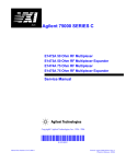
This manual contains information required to test, troubleshoot, and repair
the HP E1418A 8/16 Channel D/A Converter Module. See the HP E1418A
User’s Manual for additional module information. Figure 1-1 shows the
HP E1418A module.
Figure 1-1. HP E1418A D/A Converter Module
Safety Considerations
This product is a Safety Class I instrument that is provided with a protective
earth terminal when installed in the mainframe. The instrument, mainframe,
and all related documentation should be reviewed for familiarization with
safety markings and instructions before operation or service.
Refer to the WARNINGS page (page 6) in this manual for a summary of
safety information. Safety information for preventive maintenance, testing,
adjusting, and service follows and is also found throughout this manual.
Chapter 1
General Information
9
Warnings and
Cautions
This section contains WARNINGS which must be followed for your
protection and CAUTIONS which must be followed to avoid damage
to the equipment when performing instrument maintenance or repair.
WARNING
SERVICE-TRAINED PERSONNEL ONLY. The information in this
manual is for service-trained personnel who are familiar with
electronic circuitry and are aware of the hazards involved. To
avoid personal injury or damage to the instrument, do not
perform procedures in this manual or do any servicing unless
you are qualified to do so.
CHECK MAINFRAME POWER SETTINGS. Before applying
power, verify that the mainframe setting matches the line
voltage and that the correct fuse is installed. An uninterruptible
safety earth ground must be provided from the main power
source to the supplied power cord set.
GROUNDING REQUIREMENTS. Interruption of the protective
(grounding) conductor (inside or outside the mainframe) or
disconnecting the protective earth terminal will cause a
potential shock hazard that could result in personal injury.
(Grounding one conductor of a two-conductor outlet is not
sufficient protection.)
IMPAIRED PROTECTION. Whenever it is likely that instrument
protection has been impaired, the mainframe must be made
inoperative and be secured against any unintended operation.
REMOVE POWER IF POSSIBLE. Some procedures in this
manual may be performed with power supplied to the
mainframe while protective covers are removed. Energy
available at many points may, if contacted, result in personal
injury. (If maintenance can be performed without power applied,
the power should be removed.)
10
General Information
Chapter 1
WARNING
USING AUTOTRANSFORMERS. If the mainframe is to be
energized via an autotransformer (for voltage reduction) make
sure the common terminal is connected to neutral (that is, the
grounded side of the main’s supply).
CAPACITOR VOLTAGES. Capacitors inside the mainframe may
remain charged even when the mainframe has been
disconnected from its source of supply.
USE PROPER FUSES. For continued protection against fire
hazard, replace the line fuses only with fuses of the same
current rating and type (such as normal blow, time delay, etc.).
Do not use repaired fuses or short-circuited fuseholders.
SHOCK HAZARD. Only service-trained personnel who are
aware of the hazards involved should install, remove, or
configure the module. Before you remove any installed module,
disconnect AC power from the mainframe and from other
modules that may be connected to the module.
CHANNEL WIRING INSULATION. All channels that have a
common connection must be insulated so that the user is
protected from electrical shock. This means wiring for all
channels must be insulated as though each channel carries the
voltage of the highest voltage channel.
CAUTION
MAXIMUM VOLTAGE. The maximum voltage that can be applied to
any channel is 42 V Peak/42 Vdc. The maximum voltage from any
channel to ground is 42 V Peak/42 Vdc.
STATIC ELECTRICITY. Static electricity is a major cause of
component failure. To prevent damage to the electrical components in
the module, observe anti-static techniques whenever working on the
device.
PARTS REMOVAL. This module uses a surface mount printed circuit
assembly. Special soldering equipment is required for parts removal or
replacement. Use of standard soldering equipment will cause damage
to the printed circuit board and is not covered under warranty.
Chapter 1
General Information
11
Module Description
The HP E1418A is an 8 or 16 channel digital-to-analog converter module
for use in a VXIbus C-size mainframe. The module is a register based
device. The module can be programmed via direct register access or, with
the appropriate driver, by high level commands. This manual describes
programming the module using SCPI (Standard Commands for
Programmable Instruments) and the SCPI driver.
Each HP E1418A module is a unique instrument having its own output
buffer and error queue. Multiple modules can not be combined into a
single instrument.
Each channel can be configured to either voltage or current output mode.
When configured for voltage output, voltages in the range of -16.0 V to
+16.0 V can be set. When configured for current output, current in the
range of -0.02 to + 0.02 Amps can be set. The channel output mode can
be programmatically set, or, can be forced to either voltage or current by
mechanical jumpers on the terminal block.
Each output channel is individually configurable to be either an isolated
output or a non-isolated output. Channel configuration to isolated or
non-isolated is made by individual plug-on modules for each channel.
Module
Specifications
Module Serial
Numbers
12
General Information
Specifications are listed in Appendix A of this manual and in the
HP E1418A User’s Manual. These specifications are the performance
standards or limits against which the module may be tested.
Devices covered by this manual are identified by a serial number prefix
listed on the title page. Hewlett-Packard uses a two-part serial number in
the form USXXXXYYYYY, where US is the country of origin, XXXX is
the serial prefix, and YYYYY is the serial suffix. The serial number prefix
identifies a series of identical instruments. The serial number suffix is
assigned sequentially to each instrument. The serial number plate is located
on the right-hand shield near the backplane connectors.
Chapter 1
Ordering Options
The module may be ordered from Hewlett-Packard in a variety of
configurations. As ordered, the module may have the following options:
Description
Field Kits
HP E1418A
8-Channel D/A Converter with Non-Isolated Outputs
HP E1418A
Option 001
16-Channel D/A Converter with Non-Isolated Outputs
HP E1418A
Option 002
8-Channel D/A Converter with Isolated Outputs
HP E1418A
Option 003
16-Channel D/A Converter with Isolated Outputs
The module can also be user configured. The following field expansion
and configuration kits are available. Each field kit contains installation
instructions.
Description
Terminal Modules
Use
HP E1523A
Single Channel Isolated
plug-on module
To change a single channel
from non-isolated to isolated
output.
HP E1524A
Expansion kit, 8-Channel
Non-Isolated Outputs
To add 8 additional
non-isolated channels to an
existing 8-channel module.
HP E1525A
Expansion kit, 8-Channel
Isolated Outputs
To add 8 additional isolated
channels to an existing
8-channel module.
The standard HP E1418A Terminal Module provides screw terminals for
connections. Two other terminal options are available with the HP E1418A:
• Crimp and Insert (Option A3E)
• Ribbon Cable (Option A3H)
Chapter 1
General Information
13
Recommended
Test Equipment
Table 1-1 lists the test equipment recommended for testing and servicing
the module. Essential requirements for each piece of test equipment are
described in the Requirements column.
Table 1-1. Recommended Test Equipment
Instrument
Requirements
Recommended
Model
Use*
Controller, HP-IB
HP-IB compatibility as defined by
IEEE Standard 488-1988 and the
identical ANSI Standard MC1.1:
SH1, AH1, T2, TE0, L2, LE0, SR0,
RL0, PP0, DC0, DT0, and C1, 2, 3, 4, 5.
HP 9000 Series 300
F,O,P,T
Mainframe
Compatible with the HP E1418A
E1400B/T,
E1401A/T, or
E1401B
F,O,P,T
Command
Module, VXILink,
EPC7 Embedded
Controller
Compatible with Module
Resource manager in Slot 0
Logical address 0
Typical HP-IB address 9
Requires the downloaded driver
“E1418”
E1405B or E1406A/B
F,O,P,T
Digital Multimeter
5 1/2 or 6 1/2 digit
Voltage measurements to ± 16.8 Vdc
Current measurements to ± 0.02 A
Four-wire resistance measurements
from 50 Ω to 500 Ω
HP 3458A or
HP 34401A
O, P, T
Terminal Module
Compatible with the HP E1418A
HP E1418-60101
O, P,T
Resistor
10 kΩ , 1%, 0.25 W, metal film
P
Resistor
600 Ω , 1%, 0.25 W, metal film
Any available
supplier meeting the
requirements
P
E1418-90001
F,O,P,T
User’s Manual
* F = Functional Verification Tests, O = Operation Verification Tests, P = Performance Verification Tests, T = Troubleshooting
14
General Information
Chapter 1
Chapter 2
Installation
Introduction
This chapter contains the following topics:
•
•
•
•
Initial Inspection
Preparation for Use
Environment
Shipping Guidelines
Initial Inspection
Inspect the shipping container for damage. If the shipping container or
cushioning material is damaged, keep the container until the shipment
contents have been checked and the module has been checked mechanically
and electrically. Chapter 4 of this manual gives procedures to check the
electrical performance.
WARNING
To avoid possible hazardous electrical shock, do not perform
electrical tests if there are signs of shipping damage to any
portion of the outer enclosure (covers, panels, etc.).
If the contents are incomplete, if there is mechanical damage or defect, or if
the module does not pass the electrical performance tests, notify your
nearest Hewlett-Packard Sales and Service Office. If the shipping container
is damaged or the cushioning material shows signs of stress, notify the
carrier as well as Hewlett-Packard. Keep the shipping materials for the
carrier’s inspection.
Chapter 2
Installation
15
Preparation for Use
Chapter 1 of the HP E1418A User’s Manual contains complete instructions
for installing the module in a mainframe and installing a terminal module.
Refer to the mainframe user’s manual, command module user’s manual, and
the Installing Device Drivers installation note to prepare the mainframe.
Prepare the Module
Verify or set the module’s logical address. Refer to the HP E1418A User’s
Manual for instructions. In this manual the factory default logical address
of 72 is used.
To prepare the module for the adjustment procedures in Chapter 5, set or
verify the position of the CAL Secure Enable Jumper before installing the
module in the mainframe. (The jumper is factory set to CAL.) Figure 5-2 on
page 62 shows this jumper.
Prepare the
Terminal Module
Terminal Module
Jumpers
The procedures in this manual show the screw-type terminal module. To
prepare this terminal module, you will need to set the jumpers and make
connections. If you are using other types of terminal modules, consult the
HP E1418A User’s Manual for proper connections.
The screw-type terminal module contains jumpers that control how the
HP E1418A operates. To prepare the module for the Verification Tests in
Chapter 4 and Adjustments in Chapter 5, the terminal module jumpers must
be set to allow the module to be programmed from the backplane. The
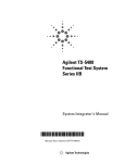
HP E1418A will operate without any jumpers installed. Figure 2-1 shows
the jumper locations and example settings.
There are two jumpers for each channel; a P/J jumper and a V/I jumper.
The two jumpers work together.
The P/J jumper sets the channel output mode to be either Program
Selectable or Jumper Selectable. When the jumper is in the program
selectable position, the channel output mode can be set via programming
commands. The program selectable position is recommended for the
Verification Tests and Adjustment procedures in this manual. In the jumper
selectable position, the channel output mode is set via the V/I jumper.
The V/I jumper sets the channel output mode to either voltage or current
when the P/J jumper is set to the Jumper Selectable position. When the P/J
jumper is set to Program Selectable, this jumper has no effect.
16
Installation
Chapter 2
Note
With no jumpers installed, the module will be in the Program Selectable
output mode.
• If you are using a terminal module dedicated to testing the HP E1418A,
you can remove all the jumpers or put the jumpers in the storage
position.
• If you are using the end-user’s terminal module, record the positions of
the jumpers. Set the P/J jumpers to the programmable position. Before
returning the module to use, restore the P/J jumpers to their original
position.
Figure 2-1. P/J and V/I Jumpers
Terminal Module
Connections
Prepare the
Command Module
Chapter 2
The Verification Tests require four-wire connections at each channel. The
Adjustment procedures can be performed using a single connections at the
CAL terminals. Additional connection information is given in the
procedures in Chapters 4 and 5 of this manual.
All verification and adjustment procedures in this manual use SCPI
(Standard Commands for Programmable Instruments). Prepare the
command module by downloading the SCPI driver named “ E1418".
Downloading instructions are given in the Installing Device Drivers
installation note.
Installation
17
Environment
The recommended operating altitude for the module is 2000 m (6000 ft) or less.
The recommended operating environment for the module is:
Environment
Temperature
Humidity
Operating
0 oC to + 55 oC
<65% relative (0 oC to + 40 oC)
non condensing
Storage and
Shipment
– 40 oC to + 75 oC
<65% relative (0 oC to + 40 oC)
non condensing
Shipping Guidelines
If you need to return the HP E1418A to Hewlett-Packard, first remove any
terminal modules before packaging for shipment. Attach a tag to the module
identifying the owner and indicating the service or repair required. Mark the
shipping container “ FRAGILE” . If you are exchanging a module, read
Assembly Exchange beginning on page 85.
In any correspondence, refer to the module by model number and full serial
number.
Hewlett-Packard recommends using shipping containers and materials
identical to those used by the factory. These materials are available through
Hewlett-Packard Sales and Service Offices.
If you use commercially available shipping materials, place the module in
an anti-static bag and wrap the module in heavy paper or plastic. Use a
strong shipping container. A double wall carton of 2400 Pa (350 psi) test
material is adequate.
Use enough shock-absorbing material (layer at least 75 mm to 110 mm,
3 in to 4 in) around the module to provide firm cushion and to prevent
movement in the container. Protect the front panel with cardboard. Seal the
container securely and mark the container “ FRAGILE” .
18
Installation
Chapter 2
Chapter 3
Operating Information
Introduction
This chapter provides operating information, preventive maintenance
instructions, and operators checks.
Operation
The HP E1418A User’s Guide is your reference for module operation.
The User’s Guide contains information about module setup, application
examples, and a complete SCPI command reference.
Querying Module
Identification and
Configuration
This example will query the module for the identification string and
determine the module configuration.
The module identification is obtained using the IEEE-488 Command
Command *IDN?.
/* Send query to the module*/
*IDN?
/* Enter a string*/
The string returned will be similar to one of the following:
HEWLETT-PACKARD,E1418A_8CH,xxxxxxxxxx,A.01.00
or
HEWLETT-PACKARD,E1418A_16CH,xxxxxxxxxx,A.01.00
The xxxxxxxxxx portion of the response string is the module serial number.
The number of channels in the module (8 or 16) is indicated by the
E1418A_8CH or E1418A_16CH portion of the returned string.
Chapter 3
Operating Information
19
The module configuration is obtained using the
DIAGnostic:CONFiguration? query.
/* Send query to the module*/
DIAG:CONF?
/* Enter six integers and decode the integers*/
The DIAG:CONF? query returns six integers. The six integers returned
contain the module configuration and have the following meaning.
Integer
Returned
Meaning
1st
Expansion Board ID in the form: 0 = present, 7 = none
(expansion board contains channels 9 through 16)
2nd
Terminal Module ID in the form
0 = screw type, 7 = none or other
3rd
Isolated/Non-isolated Channel status
A bit set to 0 indicates an isolated channel
A bit set to 1 indicates a non-isolated channel or no plug-on
module installed (DO NOT operate the module without a plug-on
module)
Bits 0 – 15 correspond to channels 1 – 16, respectively*
4th
Channel Mode
A bit set to 0 indicates a current output channel
A bit set to 1 indicates a voltage output channel
Bits 0 – 15 correspond to channels 1 – 16, respectively*
5th
Channel Output State
A bit set to 0 indicates the channel output relay is closed
A bit set to 1 indicates the channel output relay is open
Bits 0 – 15 correspond to channels 1 – 16, respectively*
6th
Channel Mode Programmable State (P/J Jumper)
A bit set to 0 indicates a channel is not mode programmable
A bit set to 1 indicates a channel is mode programmable
Bits 0 – 15 correspond to channels 1 – 16, respectively*
* For 8-channel configurations, the upper 8 bits of integers 3, 4, 5, and 6 are set to 1’s.
20
Operating Information
Chapter 3
For example, if the following six integers are returned, the module has the
configuration indicated.
Configuration Example
Integer
Decimal
Value
Configuration
1st
7
No expansion board installed
(Only channels 1 through 8)
2nd
7
No Terminal Module installed or
unknown terminal module installed
3rd
-1
All channels are non-isolated
4th
-1
All channels are voltage output channels
5th
-1
All channel outputs are disabled
(all output relays are open)
6th
-1
All channels are output mode
programmable
The following program segment demonstrates how to read the module
identification string and the configuration. The configuration integers are bit
manipulated using the C operator for bit shifting
result = result <<1
(a one bit shift to the left). The code shown in this example can be obtained
from the file prftest.c on the examples disk provided with this manual.
/** FUNCTION PROTOTYPES **/
void main (void);
void err_handler(ViSession vi, ViStatus x); /* VTL error routine
*/
void sys_err(ViSession resource);
/* Checks for SCPI programming errors */
/** GLOBAL **/
ViStatus err;
ViSession defaultRM, cmd, dac, dmm;
int num_chan;
void main (void)
{
int i,result = {0},config [6]={0},num_chan = {0};
err=viPrintf(dac, “DIAG:CONF?\n”);
/* request module configuration */
if(err VI_SUCCESS) err_handler(dac, err);
err=viScanf(dac, “%,6d”, &config);
/* returns six integers
*/
if(err VI_SUCCESS) err_handler(dac, err);
sys_err (dac);
/* SCPI error check */
Chapter 3
Operating Information
21
/* First integer */
result=config[0]; /* Expansion board */
if (result == 0)
{
printf (“Module is a 16 channel device\n”);
num_chan = 16;
}
else
{
if (result == 7)
{
printf (“Module is an 8 channel device\n”);
num_chan=8;
}
else
{
printf (“Error in DIAG:CONF ? command\n”);
printf (“First value returned was %d \n”,config[0]);
printf (“Program will terminate\n”);
pause();
abort;
}
}
/* Second integer */
result = config [1];
/* Terminal Module */
if (result == 0)
{
printf (“Module has a screw type terminal module installed\n”);
}
else
{
if (result == 7)
{
printf (“Module does NOT have a terminal module installed\n”);
}
else
{
printf (“Error in DIAG:CONF ? command\n”);
printf (“First value returned was %d \n”,config[0]);
printf (“Program will terminate\n”);
pause();
abort;
}
}
22
Operating Information
Chapter 3
/* Third integer */
result=config[2];
/* Isolated or non-isolated outputs */
if (num_chan == 8) result = result << 8; /* strip upper 8 bits */
for (i=num_chan;i>0;i— )
{
if (result > = 0x8000)
{
printf (“Channel %d is configured for non-isolated output\n”,i);
}
else
{
printf(“Channel %d is configured for isolated output\n”,i);
}
result = result << 1;
}
/* Fourth integer */
result=config[3];
/* Output Mode Voltage or Current */
if (num_chan == 8) result = result << 8; /* strip upper 8 bits */
for (i=num_chan;i>0;i— )
{
if (result > = 0x8000)
{
printf (“Channel %d is set to voltage output mode\n”,i);
}
else
{
printf(“Channel %d is set to current output mode\n”,i);
}
result = result << 1;
}
Chapter 3
Operating Information
23
/* Fifth integer */
result=config[4];
/* Channel output ON or OFF */
if (num_chan == 8) result = result << 8; /* strip upper 8 bits */
for (i=num_chan;i>0;i— )
{
if (result > = 0x8000)
{
printf (“Channel %d output is disabled\n”,i);
}
else
{
printf(“Channel %d output is enabled\n”,i);
}
result = result << 1;
}
/* Sixth integer */
result=config[5];
/* Program or Jumper Selectable channels */
if (num_chan == 8) result = result << 8; /* strip upper 8 bits */
for (i=num_chan;i>0;i— )
{
if (result >= 0x8000)
{
printf (“Channel %d output mode is programmable\n”,i);
}
else
{
printf(“Channel %d output mode is fixed and jumper selected\n”,i);
}
result = result << 1;
}
•
•
•
}
24
Operating Information
Chapter 3
Preventive Maintenance
Preventive maintenance consists of periodically cleaning the front panel, the
terminal module, and performing the Operator’s Check. Clean the module
and terminal module yearly, or more often if the module is used in very
dusty or humid areas. Disassembly of the module is not recommended for
cleaning. However, if the module is disassembled for repair or
reconfiguration, the printed circuit board assemblies (PCAs) can be blown
off with a properly grounded airgun. Remove the terminal module cover to
blow dust off the terminal printed circuit board and case. Table 3-1 shows
the recommended cleaning equipment and supplies.
Table 3-1. Recommended Cleaning Equipment and Supplies
Description
Recommended Use
Mild Soap Solution
Clean face plate panel and terminal covers.
Lint-free Cloth
Clean face plate panel and terminal covers.
Airgun with grounded
nozzle
Remove dust from the printed circuit boards
and terminal case.
WARNING
To eliminate possible electrical shock, disconnect ac power
from the mainframe and disconnect all outputs to the terminal
module before removing the module from the mainframe.
CAUTION
The printed circuit assemblies (PCAs) contain static-sensitive devices
that can be damaged by careless handling. Use static-control devices
(wrist straps, mats, and tools) when handling the module. Chapter 6
contains additional precautions for electrostatic discharge (ESD).
Chapter 3
Operating Information
25
Cleaning Procedure
Terminal Module
Use the following procedure to clean the HP E1418A.
1. Remove the terminal module from the main module.
2. Disconnect all external wiring.
3. Clean the terminal module covers with a mild soap solution and
lint-free cloth.
4. Remove the terminal module cover and blow any dust or debris from
the case.
5. Reassemble the terminal module.
6. Reconnect the external wiring.
Main Module
1. Remove the terminal module from the main module.
2. Clean the main module face plate with a mild soap solution and
lint-free cloth.
Note
Disassembling the module exposes the assemblies to ESD damage and is
usually unnecessary. Perform steps 3 through 5 only if the module is
disassembled for repairs or reconfiguration.
3. Disassemble the module following the instructions in Chapter 6.
4. Using an airgun with a grounded nozzle, remove dust from the PCA
assemblies.
5. Reassemble the module.
26
Operating Information
Chapter 3
Operator’s Checks
The operator’s check for the HP E1418A has two parts.
The first part consists of sending the SYStem:ERRor? query to the
module following power-on and entering the response. This check should be
performed after every power-on sequence. At power-on, the HP E1418A
performs a brief self-test that ensures the module can communicate with the
backplane. A successful self-test returns an integer and a string:
+0,"No Error"
Any other response indicates a failure in the module. Chapter 6 contains
troubleshooting information.
Once the power-on self-test has been checked, the operator may perform a
full self-test by sending the *TST? query and entering the response. This
query executes a full self-test that checks all circuits of the module except
the output relays. A successful self-test returns:
+0
Any other response indicates a failure. Chapter 6 contains additional
information about the self-test error codes and troubleshooting information.
Operator Check
Example
This example checks the module for errors after power-on and then
performs a full self-test.
/** FUNCTION PROTOTYPES **/
void main (void);
void err_handler(ViSession vi, ViStatus x);
void sys_err(ViSession resource);
/* VTL error routine */
/* SCPI error routine */
•
•
•
ViStatus err;
/* Global VTL error variable */
void main (void)
{
int selftest;
char selftestresults [80];
err=viPrintf(dac, “*TST?\n”);
/* run self test */
if(err VI_SUCCESS) err_handler(dac, err);
err=viScanf(dac, “%d%t”, &selftest,&selftestresults);
/* enter integer and string returned */
Chapter 3
Operating Information
27
if(err VI_SUCCESS) err_handler(dac, err);
if (selftest != ’0’)
{
printf (“Self Test failed\n”);
printf (“The first error encountered was\n”);
printf (“Error number %d %s\n”,selftest,selftestresults);
printf (“This program will terminate\n”);
pause();
abort;
}
else
{
printf (“Self Test PASSED”);
}
}
/*** VTL Error handling function ***/
void err_handler (ViSession dac, ViStatus err)
{
char buf[1024]={0};
viStatusDesc(dac,err,buf);
printf(“VTL ERROR = %s\n”, buf);
return;
} /*End of VTL error handler */
/*** SCPI error checking and reporting function ***/
void sys_err(ViSession resource) /* Test for SCPI Errors */
{
char buf [1024] = {0};
int err_no;
err = viPrintf (resource, “SYST:ERR?\n”); /* Check for an error */
if (err < VI_SUCCESS) err_handler(resource,err); /* Check VTL errors */
err = viScanf (resource,"%d%t",&err_no,&buf);
if (err < VI_SUCCESS) err_handler(resource,err); /* Check VTL errors */
while (err_no != 0) /* Report all errors in error que */
{
printf (“\nCommand Error: %d,%s\n”,err_no,buf);
err = viPrintf (resource, “SYST:ERR?\n”);
if (err < VI_SUCCESS) err_handler(resource,err); /* Check VTL errors */
err = viScanf (resource,"%d%t",&err_no,&buf);
if (err < VI_SUCCESS) err_handler(resource,err); /* Check VTL errors */
}
flushall(); /* Clean out the buffers */
err = viFlush(resource,VI_READ_BUF);
if (err < VI_SUCCESS) err_handler (resource,err); /* Check VTL errors */
err = viFlush(resource,VI_WRITE_BUF);
if (err < VI_SUCCESS) err_handler (resource,err); /* Check VTL errors */
} /* End of checking for SCPI errors */
28
Operating Information
Chapter 3
Chapter 4
Verification Tests
Introduction
Three test procedures are given in this chapter. These test procedures are
used to verify that:
• the HP E1418A is functional
(Functional Verification)
• the HP E1418A meets selected testable specifications
(Quick Verification)
• the HP E1418A meets all testable specifications
(Performance Verification)
WARNING
Do not perform any of the following verification tests unless
you are a qualified, service-trained technician and have read
the WARNINGS and CAUTIONS in Chapter 1 of this manual.
Test Conditions
Table 1-1, on page 14, lists the recommended test equipment. When
performing the test procedures, observe the following test conditions:
• The ambient temperature should be between 18 °C and 28 °C.
The temperature should be stable within ± 1 °C.
• The relative humidity should be < 65%, non-condensing.
• Install the module, apply power, and allow the module to warm up
for at least 15 minutes.
Hewlett-Packard recommends performance tests be performed at one year
intervals. In severe operating environments, or after heavy use, perform the
tests more often.
Chapter 4
Verification Tests
29]
About the Verification Tests
Three levels of verification tests are described in this chapter:
• Functional Verification Tests
• Quick Verification Tests
• Performance Verification Tests
You should perform the Functional Verification test before either the Quick
Verification or full Performance Verification tests.
Functional
Verification Test
The Functional Verification test provides a high confidence that the module
is operational. A brief self-test is performed when power is first applied to
the module. This test assures that module can communicate with the
mainframe.
The Functional Verification Test performs a more complete self-test using
the SCPI common command *TST?. If this test passes, you have a high
confidence level (90%) that the module is operational.
If the module fails the Functional Verification Test, repair is needed.
Quick Verification
Tests
The Quick Verification Test combines a Functional Verification Test with
an abbreviated set of Performance Tests to give a high confidence level that
the module is operational and meets its specifications. The Quick
Performance Test is the minimum set of tests recommended after any
service activity.
These tests check the module’s performance for normal accuracy and drift
mechanisms. These tests do not check for abnormal component failures.
Quick Verification Tests are designated with the letter “ Q” in the
Performance Verification Tests. To perform the Quick Verification Tests:
1. Perform a Functional Verification Test.
2. Perform the Performance Verification Tests designated by the letter
“ Q” in the table beginning on page 46.
If the module fails the Quick Verification Test, adjustment or repair is
needed.
30
Verification Tests
Chapter 4
Performance
Verification Tests
Performance Verification Tests give a high confidence that the module is
operational and meets its specifications. The Performance Verification Tests
can be used as acceptance tests when the module is first received.
The Performance Verification Tests should be run at the calibration interval
(Hewlett-Packard recommends a one year interval). Run the tests to
characterize the module against the specifications. Run the Performance
Verification Tests after any adjustment to verify the adjustment.
If the module fails any Performance Verification Tests, adjustment or repair
is needed.
Performance Test
Record
About Program
Examples
Note
Table 4-1, beginning on page 46, provides space to enter the results of each
Performance Verification test. The table also lists the upper and lower test
limits.
In this manual test procedures are shown with a portion of an example
program that performs the test. These examples are in ANSI C format and
complete program files are included on the disk supplied with this manual.
Most examples in this chapter are included. The examples are ASCII files
with the *.c extension.
The int data type is system dependent. These examples were developed on a
system where int is a 16-bit integer. Other systems may define int to be a
different width.
In the examples, the Hewlett-Packard VISA Transition Library is used for
I/O operations with the VXIbus. A Hewlett-Packard command module
(HP E1405/E1406) is used and controlled via HP-IB.
To use the Hewlett-Packard VISA Transition Library (abbreviated as VTL),
include the visa.h header file.
#include visa.h
Hewlett-Packard VTL function calls and data types typically begin with the
lower case letters vi. Output and enter are performed with functions named
viPrintf and viScanf. Both these functions require a session (a VTL
defined I/O function) to uniquely identify the device being controlled. In the
examples, the session has been named dac.
Chapter 4
Verification Tests
31]
SCPI drivers
In this manual, all programming examples and procedures assume the use of
the SCPI driver and HP E1406A Command Module. The HP E1418A
module is shipped with two 3.5" disks. These disks contain the SCPI driver
for the HP E1406A Command Module. One disk is in LIF format and one
disk is in DOS format. Installing Device Drivers Installation Note is
included with the disks. Follow the instructions contained in the installation
note to properly install the device driver.
Use the DIAG:DRIV:LIST? query on the command module to verify that
the correct device driver is installed. Responses to this query vary
depending upon the drivers loaded on your system. A typical response
contains a list of all drivers installed and might look like:
E1418,E1418,A.01.00,RAM;SWITCH,SWITCHBOX,A.08.00,RAM
;
SYSTEM,E1405A,A.08.00,ROM;IBASIC,IBASIC,A.04.02,ROM;
VOLTMTR,E1326A,A.05.00,ROM;SWITCH,SWITCHBOX,A.07.00,
ROM;COUNTER,E1332A,A.04.02,ROM;COUNTER,E1333A,A.04.0
2,ROM;
DIG_I/O,E1330A,A.04.03,ROM;D/A,E1328A,A.04.02,ROM
The string E1418,E1418,A.01.00, should be located somewhere
within the returned string.
SCPI Command
Reference
32
Verification Tests
The SCPI (Standard Commands for Programmable Instruments) commands
are not documented in this manual except in a general manner. Complete
SCPI commands, including syntax and parameters, applicable to the module
are documented in the HP E1418A User’s Guide.
Chapter 4
Functional Verification Test
The Functional Verification Test quickly verifies that the module is
operational. Perform this test any time to verify or check the operation.
Perform this test before beginning any Quick Verification or Performance
Verification Tests.
Functional
Verification Test
Procedure
Use the following procedure to verify the module’s operation.
1. Install the module in the mainframe and apply power.
2. Verify the module passed its power-on self-test by executing the
SYStem:ERRor? query and entering the results.
A passed self-test is indicated by the return
+0, “ No Error”
any other return value indicates a power-on failure.
Note
If an incorrect module address is used, the module will not respond.
Verify the module’s address before troubleshooting.
3. Execute the full self-test by sending the *TST? query and entering
the result.
A passed self-test is indicated by the return
+0
Any other return value indicates a failure. Additional information
about the self-test results and self-test error codes is given in
Chapter 6 beginning on page 73.
Functional
Verification Test
Example
Chapter 4
An example of the Functional Verification Test is shown beginning on
page 27.
Verification Tests
33]
Performance Verification Tests
These procedures test the electrical performance of the HP E1418A using
the specification in Appendix A as the performance standards. These tests
are suitable for incoming inspections, troubleshooting, and preventive
measures.
DC Voltage Output
Verification
This procedure tests the dc voltage output performance of the module.
1. For each channel in the module, connect the 10 kΩ resistor and
DMM as shown in Figure 4-1. Channel 1 connections are shown in
the figure. Connect the other channels in a similar manner. Set the
DMM to measure dc volts.
Figure 4-1. DC Voltage Output Connections (Channel 1)
2. Set the channel to output each of the following voltages:
+16.00
– 4.00
+12.00
– 8.00
+ 8.00
–12.00
+ 4.00
–16.00
0.00
Use the APPLyn:VOLTage xx.xx command, where n is the
channel number and xx.xx is the voltage to output.
3. For each voltage, measure the output voltage with the DMM, enter it
in the table beginning on page 46, and compare the voltage output to
the limits shown in the table.
34
Verification Tests
Chapter 4
4. Open the channel output relay by sending the OUTPutn OFF
command, where n is the channel number.
5. Change the connections to the next channel and repeat steps 2, 3,
and 4.
6. Repeat steps 2, 3, 4, and 5 for each channel.
DC Voltage
Compliance Current
This test checks the compliance current in dc voltage.
1. For each channel in the module, connect the 600 Ω resistor and the
DMM as shown in Figure 4-2. Channel 1 connections are shown in
the figure. Connect the other channels in a similar manner. Set the
DMM to measure dc voltage.
Figure 4-2. DC Voltage Output Connections (Channel 1)
2. Set the channel to output +12.00 V. Use the
APPLyn:VOLTage 12.00 command, where n is the channel
number.
3. Measure the output voltage with the DMM, enter it in the table
beginning on page 46, and compare the measured voltage to the limits
shown in the table. The compliance current is inferred from the
voltage across the resistor.
4. Open the channel output relay by sending the OUTPutn OFF
command, where n is the channel number.
5. Change the connections to the next channel and repeat steps 2, 3,
and 4.
6. Repeat steps 2, 3, 4, and 5 for each channel.
Chapter 4
Verification Tests
35]
DC Voltage Short
Circuit Output
Current
This test checks the short circuit output current for each channel.
1. For each channel in the module, connect the DMM as shown in
Figure 4-3. Channel 1 connections are shown in the figure. Connect
the other channels in a similar manner. Set the DMM to measure dc
current (the DMM should have a current shunt of 100 Ω or less for
this test).
Figure 4-3. DC Voltage Output Connections (Channel 1)
2. Set the channel to output +16.00 V. Use the
APPLyn:VOLTage 16.00 command, where n is the channel
number.
3. Measure the output current with the DMM, enter it in the table
beginning on page 46, and compare the measured current to the limits
shown in the table.
4. Open the channel output relay by sending the OUTPutn OFF
command, where n is the channel number.
5. Change the connections to the next channel and repeat steps 2, 3,
and 4.
6. Repeat steps 2, 3, 4, and 5 for each channel.
36
Verification Tests
Chapter 4
DC Current
Verification
This test checks the dc current output performance of the module.
1. For each channel in the module, connect the DMM as shown in
Figure 4-4. Channel 1 connections are shown in the figure. Connect
the other channels in a similar manner. Set the DMM to measure dc
current.
Figure 4-4. DC Current Output Connections (Channel 1)
2. Set the channel to output each of the following currents:
+0.020
–0.005
+0.015
–0.010
+0.010
–0.015
+0.005
–0.020
0.000
Use the APPLyn:CURRent x.xxx command, where n is the
channel number and x.xxx is the current to output.
3. For each current, measure the output current with the DMM, enter it
in the table beginning on page 46, and compare the current output to
the limits shown in the table.
4. Open the channel output relay by sending the OUTPutn OFF
command, where n is the channel number.
5. Change the connections to the next channel and repeat steps 2, 3,
and 4.
6. Repeat steps 2, 3, 4, and 5 for each channel.
Chapter 4
Verification Tests
37]
Performance
Verification Tests
Example
This example demonstrates a full performance verification test of the
module. The code shown in this example can be obtained from the file
prftest.c on the examples disk provided with this manual.
/** FUNCTION PROTOTYPES **/
void main (void);
void err_handler(ViSession vi, ViStatus x); /* VTL error routine */
void sys_err(ViSession resource); /* Checks for SCPI programming errors */
void pause();
/* Waits for a keystroke to continue program execution */
void dcv_check ();
/* Voltage output verification test */
void compliance_check ();
/* Compliance current verification test */
void maxcurrent_check ();
/* Short circuit output current verification test */
void current_check ();
/* Current output verification test */
/* DMM routines
*/
void dmm_setup (char function [6], char range [6]); /* Set function and range for DMM */
float dmm_measure ();
/* get the dmm measurement */
/** GLOBAL **/
ViStatus err;
ViSession defaultRM, cmd, dac, dmm;
int num_chan;
/* 8 or 16 */
float dcv_results [16][9]={0};
/* Voltage output verification test results */
float compliance_results [16] = {0}; /* Compliance current verification test results */
float maxcurrent_results [16] = {0}; /* Short circuit output current verification test results */
float current_results [16][9] = {0};
/* Current output verification test results */
void main (void)
{
dcv_check ();
compliance_check ();
maxcurrent_check ();
current_check ();
}
38
Verification Tests
Chapter 4
/*** Routine to perform the dcv performance test ***/
void dcv_check ()
{
float v_out [9] = {16, 12, 8, 4, 0, -4,-8, -12, -16}; /* Voltages to output during test */
int i,j,opc_check;
char function [6] = {“VOLT:DC\0"},range [6] = {”100\0"};
dmm_setup (function,range);
printf (“Voltage Output Check on %d channels”,num_chan);
printf (“\n\n”);
printf (“DC VOLTAGE OUTPUT PERFORMANCE TEST\n\n”);
for (i = 0;i != num_chan;i++)
{
/** connection instructions **/
printf (“\tChannel %d test\n”,i+1);
printf (“1.\tMake a four-wire connection from channel %d \n”,i+1);
printf (“\tto a 10,000 Ohm resistor.\n”);
printf (“2.\tMake a two-wire connection from the DMM to\n”);
printf (“\tthe 10,000 Ohm resistor.\n”);
printf (“3.\tThe DMM is set to make DC Volts Measurements on \n”);
printf (“\tthe 100 V range.\n”);
printf (“4.\tFor each channel in the HP E1418A,\n”);
printf (“\t\tOutput 16 V, 12 V, 8 V, 4 V, 0 V, -4 V, -8 V, -12 V, -16 V.\n”);
printf (“\t\tMeasure each voltage output on the DMM.\n”);
printf (“\n\n”);
pause();
/** voltage output loop **/
for (j=0;j<9;j++)
{
err=viPrintf(dac, “APPLY%d:VOLTAGE %f;*OPC?\n”,i+1,v_out[j]); /* voltage output*/
if(err VI_SUCCESS) err_handler(dac, err);
err=viScanf(dac, “%d”, &opc_check); /* enter OPC integer */
if(err VI_SUCCESS) err_handler(dac, err);
dcv_results [i][j] = dmm_measure();
}
printf (“\nChannel %d Voltage Output Test Done\n\n”,i+1);
err=viPrintf(dac, “OUTPUT%d OFF;*OPC?\n”,i+1); /* Turn output off */
if(err VI_SUCCESS) err_handler(dac, err);
err=viScanf(dac, “%d”, &opc_check);
/* enter OPC integer */
if(err VI_SUCCESS) err_handler(dac, err);
sys_err (dac);
/* SCPI error check */
}
printf (“\n\nEnd of DC Voltage Output Test\n\n”);
err=viPrintf(dac, “*RST\n”);
if(err VI_SUCCESS) err_handler(dac, err);
}
/*** End of dcv_check ***/
Chapter 4
Verification Tests
39]
/*** Routine to perform the compliance current performance test ***/
void compliance_check ()
{
float v_out = {12};
/* Voltage to output */
int i,opc_check;
char function [6] = {“VOLT:DC\0"},range [6] = {”100\0"};
dmm_setup (function,range);
printf (“\n\nCompliance Current Verification Test\n\n”);
for (i = 0;i != num_chan;i++)
{
/** connection instructions **/
printf (“\tChannel %d\n”,i+1);
printf (“1.\tMake a four-wire connection from channel %d \n”,i+1);
printf (“\tto a 600 Ohm resistor.\n”);
printf (“2.\tMake a two-wire connection from the DMM to\n”);
printf (“\tthe 600 Ohm resistor.\n”);
printf (“3.\tThe DMM is set to make DC Volts Measurements on \n”);
printf (“\tthe 100 V range.\n”);
printf (“4.\tEach channel is set to output 12 V\n”);
printf (“\t\tMeasure the voltage drop across the resistor output.\n”);
printf (“\n\n”);
pause();
err=viPrintf(dac, “APPLY%d:VOLTAGE %f;*OPC?\n”,i+1,v_out); /* voltage output */
if(err VI_SUCCESS) err_handler(dac, err);
err=viScanf(dac, “%d”, &opc_check); /* enter OPC integer */
if(err VI_SUCCESS) err_handler(dac, err);
compliance_results [i] = dmm_measure();
err=viPrintf(dac, “OUTPUT%d OFF;*OPC?\n”,i+1); /* Turn output off */
if(err VI_SUCCESS) err_handler(dac, err);
err=viScanf(dac, “%d”, &opc_check);
/* enter OPC integer */
if(err VI_SUCCESS) err_handler(dac, err);
sys_err (dac);
/* SCPI error check */
}
printf (“\n\nend of Compliance Current Test\n\n”);
err=viPrintf(dac, “*RST\n”);
/* reset the dac
*/
if(err VI_SUCCESS) err_handler(dac, err);
}
/*** End of compliance_check ***/
40
Verification Tests
Chapter 4
/*** Routine to perform the short circuit output current performance test ***/
void maxcurrent_check ()
{
float v_out = {16}; /*voltage to output*/
int i,opc_check;
char function [6] = {“CURR:DC\0"},range [6] = {”0.100\0"};
dmm_setup (function,range);
printf (“\n\nShort Circuit Output Current Verification Test\n\n”);
for (i = 0;i != num_chan;i++)
{
/** connection instructions **/
printf (“\tChannel %d\n”,i+1);
printf (“1.\tMake a four-wire connection from channel %d \n”,i+1);
printf (“\tto the DMM current input terminals\n”);
printf (“2.\tThe DMM is set to make DC current Measurements on \n”);
printf (“\tthe 100 mA range.\n”);
printf (“3.\tEach channel is set to output 16 V\n”);
printf (“\t\tMeasure the current flowing through the DMM.\n”);
printf (“\n\n”);
pause();
err=viPrintf(dac, “APPLY%d:VOLTAGE %f;*OPC?\n”,i+1,v_out); /* voltage output */
if(err VI_SUCCESS) err_handler(dac, err);
err=viScanf(dac, “%d”, &opc_check);
/* enter OPC integer */
if(err VI_SUCCESS) err_handler(dac, err);
maxcurrent_results [i] = dmm_measure();
err=viPrintf(dac, “OUTPUT%d OFF;*OPC?\n”,i+1); /* Turn output off */
if(err VI_SUCCESS) err_handler(dac, err);
err=viScanf(dac, “%d”, &opc_check);
/* enter OPC integer */
if(err VI_SUCCESS) err_handler(dac, err);
sys_err (dac);
/* SCPI error check */
}
printf (“End of Short Circuit Output Current Test”);
err=viPrintf(dac, “*RST\n”);
if(err VI_SUCCESS) err_handler(dac, err);
}
/*** End of maxcurrent_check ***/
Chapter 4
Verification Tests
41]
/*** Routine to perform the current performance test ***/
void current_check ()
{
float i_out [9] = {0.02F, 0.015F, 0.01F,0.005F, 0, -0.005F,-0.01F, -0.015F, -0.02F};
/* Currents to output */
int i,j,opc_check; */
char function [6] = {“CURR:DC\0"},range [6] = {”0.100\0"};
dmm_setup (function,range);
printf (“\n\n”);
printf (“DC CURRENT OUTPUT PERFORMANCE TEST\n\n\n\n”);
for (i = 0;i != num_chan;i++)
{
/** connection instructions **/
printf (“Channel %d\n”,i+1);
printf (“1.\tMake a two-wire connection from channel %d \n”,i+1);
printf (“\tto the DMM current input terminals.\n”);
printf (“2.\tThe DMM is set to make DC current measurements on \n”);
printf (“\tthe 100 mA range.\n”);
printf (“3.\tFor each channel in the HP E1418A,\n”);
printf (“\t\tOutput 20 mA, 15 mA, 10 mA, 5 mA, 0 mA, -5 mA, -10 mA, -15 mA, -20 mA.\n”);
printf (“\t\tMeasure each current output.\n”);
printf (“\n\n”);
pause();
/** current output loop **/
for (j=0;j<9 ;j++)
{
err=viPrintf(dac, “APPLY%d:CURRENT %f;*OPC?\n”,i+1,i_out[j]); /* voltage output */
if(err VI_SUCCESS) err_handler(dac, err);
err=viScanf(dac, “%d”, &opc_check);
/* enter OPC integer */
if(err VI_SUCCESS) err_handler(dac, err);
current_results [i][j] = dmm_measure();
}
printf (“Current Output Test on channel %d complete\n\n”,i+1);
err=viPrintf(dac, “OUTPUT%d OFF;*OPC?\n”,i+1); /* Turn output off */
if(err VI_SUCCESS) err_handler(dac, err);
err=viScanf(dac, “%d”, &opc_check);
/* enter OPC integer */
if(err VI_SUCCESS) err_handler(dac, err);
sys_err (dac);
/* SCPI error check */
}
printf (“Current Output Verification Test completed”);
err=viPrintf(dac, “*RST\n”);
/* reset the dac
*/
if(err VI_SUCCESS) err_handler(dac, err);
}
/*** End of current_check ***/
42
Verification Tests
Chapter 4
Performance Test Record
Table 4-1 is a form you can copy and use to record the performance
verification test results of the HP E1418A. This table shows the output
accuracy, measurement uncertainty, and the test accuracy ratio (TAR)
values. The test marked with a “ Q” in the table are the Quick Verification
Tests.
Test Limits
The test limits are defined using the 90-day specifications. Appendix A lists
the HP E1418A specifications.
Measurement
Uncertainty
Measurement uncertainty has been calculated using the HP 34401A 90-day
specifications. The HP 34401A is set to the 61⁄2 digit mode for all
calculations. In both the voltage and current measurement mode, the
measurement uncertainty is given as:
M.U. = % of reading + % of range
Voltage Output
Measurements
The 100 V range is used for the voltage output measurements.
The specification is given as:
M.U. = ± (0.0035% of reading + 0.0006% of range)
Chapter 4
HP E1418A
Output
% of reading
% of range
Measurement
Uncertainty
+ 16.00 V
0.00056 V
0.0006 V
± 0.00116 V
+ 12.00 V
0.00042 V
0.0006 V
± 0.00102 V
+ 8.00 V
0.00028 V
0.0006 V
± 0.00088 V
+ 4.00 V
0.00014 V
0.0006 V
± 0.00074 V
0.00 V
0.00000 V
0.0006 V
± 0.00060 V
– 4.00 V
0.00014 V
0.0006 V
± 0.00074 V
– 8.00 V
0.00028 V
0.0006 V
± 0.00088 V
– 12.00 V
0.00042 V
0.0006 V
± 0.00102 V
– 16.00 V
0.00056 V
0.0006 V
± 0.00116 V
Verification Tests
43]
DC Compliance
Current Measurements
The 100 V range is used for the compliance current test. (The compliance
current is inferred from the voltage developed across the resistor).
M.U. = ± (0.035% of reading + 0.0006% of range)
M.U. = ± (0.00042 + 0.0006) = 0.00102 V
DC Short Circuit
Current Measurements
The 100 mA range is used for the short circuit current measurement.
M.U. = ± (0.030% of reading + 0.005% of range)
M.U. = ± (0.000018 + 0.000005) = 0.000023 A
Current Output
Measurements
The 100 mA range is used for the current output measurements.
M.U. = ± (0.030% of reading + 0.005% of range)
Test Accuracy
Ratio (TAR)
HP E1418A
Output
% of reading
% of range
Measurement
Uncertainty
+ 0.020 A
0.000006 A
0.000005 A
± 0.000011 A
+ 0.015 A
0.0000045 A
0.000005 A
± 0.0000095 A
+ 0.010 A
0.000003 A
0.000005 A
± 0.000008 A
+ 0.005 A
0.0000015 A
0.000005 A
± 0.0000065 A
0.000 A
0.00000 A
0.000005 A
± 0.000005 A
– 0.005 A
0.0000015 A
0.000005 A
± 0.0000065 A
– 0.010 A
0.000003 A
0.000005 A
± 0.000008 A
– 0.015 A
0.0000045 A
0.000005 A
± 0.0000095 A
– 0.020 A
0.000006 A
0.000005 A
± 0.000011 A
The Test Accuracy Ratio (TAR) is defined as:
Maximum Allowed − Input
TAR = Measurement Uncertainty
Where Maximum Allowed, Input, and Measurement Uncertainty are all in
Vdc or Amps.
The TAR is listed in table 4-1.
44
Verification Tests
Chapter 4
Table 4-1. Performance Test Record
Test Facility:
Name
Report No.
Address
Date
City/State
Customer
Phone
Tested by
Model HP E1418A
Ambient Temperature
Serial No.
Relative Humidity
Options
Firmware Rev
Notes:
Test Equipment Used
Chapter 4
Model
Trace Number
Cal Due Date
Verification Tests
45]
Quick
Check
Channel
E1418A
Output
Min
Measured
Max
M.U.
TAR
Voltage Output Check
Q
1
+16.000 V
+15.989 V
__________
+16.011 V
1.16E-3 V
9.5:1
1
+12.000 V
+11.991 V
__________
+12.009 V
1.02E-3 V
8.8:1
1
+8.000 V
+7.993 V
__________
+8.007 V
8.80E-4 V
7.9:1
1
+4.000 V
+3.995 V
__________
+4.005 V
7.40E-4 V
6.7:1
1
0.000 V
– 0.003 V
__________
+0.003 V
6.00E-4 V
5:1
1
-4.000 V
–4.005
__________
–3.995 V
7.40E-4 V
6.7:1
1
-8.000 V
–8.007
__________
–7.993 V
8.80E-4 V
7.9:1
1
-12.000 V
–12.009
__________
–11.991 V
1.02E-3 V
8.8:1
Q
1
-16.000 V
–16.011
__________
–15.989 V
1.16E-3 V
9.5:1
Q
2
+16.000 V
+15.989 V
__________
+16.011 V
1.16E-3 V
9.5:1
2
+12.000 V
+11.991 V
__________
+12.009 V
1.02E-3 V
8.8:1
2
+8.000 V
+7.993 V
__________
+8.007 V
8.80E-4 V
7.9:1
2
+4.000 V
+3.995 V
__________
+4.005 V
7.40E-4 V
6.7:1
2
0.000 V
– 0.003 V
__________
+0.003 V
6.00E-4 V
5:1
2
-4.000 V
–4.005
__________
–3.995 V
7.40E-4 V
6.7:1
2
-8.000 V
–8.007
__________
–7.993 V
8.80E-4 V
7.9:1
2
-12.000 V
–12.009
__________
–11.991 V
1.02E-3 V
8.8:1
Q
2
-16.000 V
–16.011
__________
–15.989 V
1.16E-3 V
9.5:1
Q
3
+16.000 V
+15.989 V
__________
+16.011 V
1.16E-3 V
9.5:1
3
+12.000 V
+11.991 V
__________
+12.009 V
1.02E-3 V
8.8:1
3
+8.000 V
+7.993 V
__________
+8.007 V
8.80E-4 V
7.9:1
3
+4.000 V
+3.995 V
__________
+4.005 V
7.40E-4 V
6.7:1
3
0.000 V
– 0.003 V
__________
+0.003 V
6.00E-4 V
5:1
3
-4.000 V
–4.005
__________
–3.995 V
7.40E-4 V
6.7:1
3
-8.000 V
–8.007
__________
–7.993 V
8.80E-4 V
7.9:1
3
-12.000 V
–12.009
__________
–11.991 V
1.02E-3 V
8.8:1
3
-16.000 V
–16.011
__________
–15.989 V
1.16E-3 V
9.5:1
Q
Q
Q
Q
46
Verification Tests
Chapter 4
Quick
Check
Channel
E1418A
Output
Min
Measured
Max
M.U.
TAR
Q
4
+16.000 V
+15.989 V
__________
+16.011 V
1.16E-3 V
9.5:1
4
+12.000 V
+11.991 V
__________
+12.009 V
1.02E-3 V
8.8:1
4
+8.000 V
+7.993 V
__________
+8.007 V
8.80E-4 V
7.9:1
4
+4.000 V
+3.995 V
__________
+4.005 V
7.40E-4 V
6.7:1
4
0.000 V
– 0.003 V
__________
+0.003 V
6.00E-4 V
5:1
4
-4.000 V
–4.005
__________
–3.995 V
7.40E-4 V
6.7:1
4
-8.000 V
–8.007
__________
–7.993 V
8.80E-4 V
7.9:1
4
-12.000 V
–12.009
__________
–11.991 V
1.02E-3 V
8.8:1
Q
4
-16.000 V
–16.011
__________
–15.989 V
1.16E-3 V
9.5:1
Q
5
+16.000 V
+15.989 V
__________
+16.011 V
1.16E-3 V
9.5:1
5
+12.000 V
+11.991 V
__________
+12.009 V
1.02E-3 V
8.8:1
5
+8.000 V
+7.993 V
__________
+8.007 V
8.80E-4 V
7.9:1
5
+4.000 V
+3.995 V
__________
+4.005 V
7.40E-4 V
6.7:1
5
0.000 V
– 0.003 V
__________
+0.003 V
6.00E-4 V
5:1
5
-4.000 V
–4.005
__________
–3.995 V
7.40E-4 V
6.7:1
5
-8.000 V
–8.007
__________
–7.993 V
8.80E-4 V
7.9:1
5
-12.000 V
–12.009
__________
–11.991 V
1.02E-3 V
8.8:1
Q
5
-16.000 V
–16.011
__________
–15.989 V
1.16E-3 V
9.5:1
Q
6
+16.000 V
+15.989 V
__________
+16.011 V
1.16E-3 V
9.5:1
6
+12.000 V
+11.991 V
__________
+12.009 V
1.02E-3 V
8.8:1
6
+8.000 V
+7.993 V
__________
+8.007 V
8.80E-4 V
7.9:1
6
+4.000 V
+3.995 V
__________
+4.005 V
7.40E-4 V
6.7:1
6
0.000 V
– 0.003 V
__________
+0.003 V
6.00E-4 V
5:1
6
-4.000 V
–4.005
__________
–3.995 V
7.40E-4 V
6.7:1
6
-8.000 V
–8.007
__________
–7.993 V
8.80E-4 V
7.9:1
6
-12.000 V
–12.009
__________
–11.991 V
1.02E-3 V
8.8:1
6
-16.000 V
–16.011
__________
–15.989 V
1.16E-3 V
9.5:1
Q
Q
Q
Q
Chapter 4
Verification Tests
47]
Quick
Check
Channel
E1418A
Output
Min
Measured
Max
M.U.
TAR
Q
7
+16.000 V
+15.989 V
__________
+16.011 V
1.16E-3 V
9.5:1
7
+12.000 V
+11.991 V
__________
+12.009 V
1.02E-3 V
8.8:1
7
+8.000 V
+7.993 V
__________
+8.007 V
8.80E-4 V
7.9:1
7
+4.000 V
+3.995 V
__________
+4.005 V
7.40E-4 V
6.7:1
7
0.000 V
– 0.003 V
__________
+0.003 V
6.00E-4 V
5:1
7
-4.000 V
–4.005
__________
–3.995 V
7.40E-4 V
6.7:1
7
-8.000 V
–8.007
__________
–7.993 V
8.80E-4 V
7.9:1
7
-12.000 V
–12.009
__________
–11.991 V
1.02E-3 V
8.8:1
Q
7
-16.000 V
–16.011
__________
–15.989 V
1.16E-3 V
9.5:1
Q
8
+16.000 V
+15.989 V
__________
+16.011 V
1.16E-3 V
9.5:1
8
+12.000 V
+11.991 V
__________
+12.009 V
1.02E-3 V
8.8:1
8
+8.000 V
+7.993 V
__________
+8.007 V
8.80E-4 V
7.9:1
8
+4.000 V
+3.995 V
__________
+4.005 V
7.40E-4 V
6.7:1
8
0.000 V
– 0.003 V
__________
+0.003 V
6.00E-4 V
5:1
8
-4.000 V
–4.005
__________
–3.995 V
7.40E-4 V
6.7:1
8
-8.000 V
–8.007
__________
–7.993 V
8.80E-4 V
7.9:1
8
-12.000 V
–12.009
__________
–11.991 V
1.02E-3 V
8.8:1
Q
8
-16.000 V
–16.011
__________
–15.989 V
1.16E-3 V
9.5:1
Q
9
+16.000 V
+15.989 V
__________
+16.011 V
1.16E-3 V
9.5:1
9
+12.000 V
+11.991 V
__________
+12.009 V
1.02E-3 V
8.8:1
9
+8.000 V
+7.993 V
__________
+8.007 V
8.80E-4 V
7.9:1
9
+4.000 V
+3.995 V
__________
+4.005 V
7.40E-4 V
6.7:1
9
0.000 V
– 0.003 V
__________
+0.003 V
6.00E-4 V
5:1
9
-4.000 V
–4.005
__________
–3.995 V
7.40E-4 V
6.7:1
9
-8.000 V
–8.007
__________
–7.993 V
8.80E-4 V
7.9:1
9
-12.000 V
–12.009
__________
–11.991 V
1.02E-3 V
8.8:1
9
-16.000 V
–16.011
__________
–15.989 V
1.16E-3 V
9.5:1
Q
Q
Q
Q
48
Verification Tests
Chapter 4
Quick
Check
Channel
E1418A
Output
Min
Measured
Max
M.U.
TAR
Q
10
+16.000 V
+15.989 V
__________
+16.011 V
1.16E-3 V
9.5:1
10
+12.000 V
+11.991 V
__________
+12.009 V
1.02E-3 V
8.8:1
10
+8.000 V
+7.993 V
__________
+8.007 V
8.80E-4 V
7.9:1
10
+4.000 V
+3.995 V
__________
+4.005 V
7.40E-4 V
6.7:1
10
0.000 V
– 0.003 V
__________
+0.003 V
6.00E-4 V
5:1
10
-4.000 V
–4.005
__________
–3.995 V
7.40E-4 V
6.7:1
10
-8.000 V
–8.007
__________
–7.993 V
8.80E-4 V
7.9:1
10
-12.000 V
–12.009
__________
–11.991 V
1.02E-3 V
8.8:1
Q
10
-16.000 V
–16.011
__________
–15.989 V
1.16E-3 V
9.5:1
Q
11
+16.000 V
+15.989 V
__________
+16.011 V
1.16E-3 V
9.5:1
11
+12.000 V
+11.991 V
__________
+12.009 V
1.02E-3 V
8.8:1
11
+8.000 V
+7.993 V
__________
+8.007 V
8.80E-4 V
7.9:1
11
+4.000 V
+3.995 V
__________
+4.005 V
7.40E-4 V
6.7:1
11
0.000 V
– 0.003 V
__________
+0.003 V
6.00E-4 V
5:1
11
-4.000 V
–4.005
__________
–3.995 V
7.40E-4 V
6.7:1
11
-8.000 V
–8.007
__________
–7.993 V
8.80E-4 V
7.9:1
11
-12.000 V
–12.009
__________
–11.991 V
1.02E-3 V
8.8:1
Q
11
-16.000 V
–16.011
__________
–15.989 V
1.16E-3 V
9.5:1
Q
12
+16.000 V
+15.989 V
__________
+16.011 V
1.16E-3 V
9.5:1
12
+12.000 V
+11.991 V
__________
+12.009 V
1.02E-3 V
8.8:1
12
+8.000 V
+7.993 V
__________
+8.007 V
8.80E-4 V
7.9:1
12
+4.000 V
+3.995 V
__________
+4.005 V
7.40E-4 V
6.7:1
12
0.000 V
– 0.003 V
__________
+0.003 V
6.00E-4 V
5:1
12
-4.000 V
–4.005
__________
–3.995 V
7.40E-4 V
6.7:1
12
-8.000 V
–8.007
__________
–7.993 V
8.80E-4 V
7.9:1
12
-12.000 V
–12.009
__________
–11.991 V
1.02E-3 V
8.8:1
12
-16.000 V
–16.011
__________
–15.989 V
1.16E-3 V
9.5:1
Q
Q
Q
Q
Chapter 4
Verification Tests
49]
Quick
Check
Channel
E1418A
Output
Min
Measured
Max
M.U.
TAR
Q
13
+16.000 V
+15.989 V
__________
+16.011 V
1.16E-3 V
9.5:1
13
+12.000 V
+11.991 V
__________
+12.009 V
1.02E-3 V
8.8:1
13
+8.000 V
+7.993 V
__________
+8.007 V
8.80E-4 V
7.9:1
13
+4.000 V
+3.995 V
__________
+4.005 V
7.40E-4 V
6.7:1
13
0.000 V
– 0.003 V
__________
+0.003 V
6.00E-4 V
5:1
13
-4.000 V
–4.005
__________
–3.995 V
7.40E-4 V
6.7:1
13
-8.000 V
–8.007
__________
–7.993 V
8.80E-4 V
7.9:1
13
-12.000 V
–12.009
__________
–11.991 V
1.02E-3 V
8.8:1
Q
13
-16.000 V
–16.011
__________
–15.989 V
1.16E-3 V
9.5:1
Q
14
+16.000 V
+15.989 V
__________
+16.011 V
1.16E-3 V
9.5:1
14
+12.000 V
+11.991 V
__________
+12.009 V
1.02E-3 V
8.8:1
14
+8.000 V
+7.993 V
__________
+8.007 V
8.80E-4 V
7.9:1
14
+4.000 V
+3.995 V
__________
+4.005 V
7.40E-4 V
6.7:1
14
0.000 V
– 0.003 V
__________
+0.003 V
6.00E-4 V
5:1
14
-4.000 V
–4.005
__________
–3.995 V
7.40E-4 V
6.7:1
14
-8.000 V
–8.007
__________
–7.993 V
8.80E-4 V
7.9:1
14
-12.000 V
–12.009
__________
–11.991 V
1.02E-3 V
8.8:1
Q
14
-16.000 V
–16.011
__________
–15.989 V
1.16E-3 V
9.5:1
Q
15
+16.000 V
+15.989 V
__________
+16.011 V
1.16E-3 V
9.5:1
15
+12.000 V
+11.991 V
__________
+12.009 V
1.02E-3 V
8.8:1
15
+8.000 V
+7.993 V
__________
+8.007 V
8.80E-4 V
7.9:1
15
+4.000 V
+3.995 V
__________
+4.005 V
7.40E-4 V
6.7:1
15
0.000 V
– 0.003 V
__________
+0.003 V
6.00E-4 V
5:1
15
-4.000 V
–4.005
__________
–3.995 V
7.40E-4 V
6.7:1
15
-8.000 V
–8.007
__________
–7.993 V
8.80E-4 V
7.9:1
15
-12.000 V
–12.009
__________
–11.991 V
1.02E-3 V
8.8:1
15
-16.000 V
–16.011
__________
–15.989 V
1.16E-3 V
9.5:1
Q
Q
Q
Q
50
Verification Tests
Chapter 4
Quick
Check
Channel
E1418A
Output
Min
Measured
Max
M.U.
TAR
Q
16
+16.000 V
+15.989 V
__________
+16.011 V
1.16E-3 V
9.5:1
16
+12.000 V
+11.991 V
__________
+12.009 V
1.02E-3 V
8.8:1
16
+8.000 V
+7.993 V
__________
+8.007 V
8.80E-4 V
7.9:1
16
+4.000 V
+3.995 V
__________
+4.005 V
7.40E-4 V
6.7:1
16
0.000 V
– 0.003 V
__________
+0.003 V
6.00E-4 V
5:1
16
-4.000 V
–4.005
__________
–3.995 V
7.40E-4 V
6.7:1
16
-8.000 V
–8.007
__________
–7.993 V
8.80E-4 V
7.9:1
16
-12.000 V
–12.009
__________
–11.991 V
1.02E-3 V
8.8:1
16
-16.000 V
–16.011
__________
–15.989 V
1.16E-3 V
9.5:1
Q
Q
DC Voltage Compliance Current Check
Chapter 4
1
+12.000 V
+11.991 V
__________
+12.009 V
1.02E-3 V
8.8:1
2
+12.000 V
+11.991 V
__________
+12.009 V
1.02E-3 V
8.8:1
3
+12.000 V
+11.991 V
__________
+12.009 V
1.02E-3 V
8.8:1
4
+12.000 V
+11.991 V
__________
+12.009 V
1.02E-3 V
8.8:1
5
+12.000 V
+11.991 V
__________
+12.009 V
1.02E-3 V
8.8:1
6
+12.000 V
+11.991 V
__________
+12.009 V
1.02E-3 V
8.8:1
7
+12.000 V
+11.991 V
__________
+12.009 V
1.02E-3 V
8.8:1
8
+12.000 V
+11.991 V
__________
+12.009 V
1.02E-3 V
8.8:1
9
+12.000 V
+11.991 V
__________
+12.009 V
1.02E-3 V
8.8:1
10
+12.000 V
+11.991 V
__________
+12.009 V
1.02E-3 V
8.8:1
11
+12.000 V
+11.991 V
__________
+12.009 V
1.02E-3 V
8.8:1
12
+12.000 V
+11.991 V
__________
+12.009 V
1.02E-3 V
8.8:1
13
+12.000 V
+11.991 V
__________
+12.009 V
1.02E-3 V
8.8:1
14
+12.000 V
+11.991 V
__________
+12.009 V
1.02E-3 V
8.8:1
15
+12.000 V
+11.991 V
__________
+12.009 V
1.02E-3 V
8.8:1
16
+12.000 V
+11.991 V
__________
+12.009 V
1.02E-3 V
8.8:1
Verification Tests
51]
Quick
Check
Channel
E1418A
Output
Min
Measured
Max
M.U.
TAR
DC Voltage Short Circuit Current Check
1
+16.000 V
NA
__________
0.060 A
2.3E-5 A
NA
2
+16.000 V
NA
__________
0.060 A
2.3E-5 A
NA
3
+16.000 V
NA
__________
0.060 A
2.3E-5 A
NA
4
+16.000 V
NA
__________
0.060 A
2.3E-5 A
NA
5
+16.000 V
NA
__________
0.060 A
2.3E-5 A
NA
6
+16.000 V
NA
__________
0.060 A
2.3E-5 A
NA
7
+16.000 V
NA
__________
0.060 A
2.3E-5 A
NA
8
+16.000 V
NA
__________
0.060 A
2.3E-5 A
NA
9
+16.000 V
NA
__________
0.060 A
2.3E-5 A
NA
10
+16.000 V
NA
__________
0.060 A
2.3E-5 A
NA
11
+16.000 V
NA
__________
0.060 A
2.3E-5 A
NA
12
+16.000 V
NA
__________
0.060 A
2.3E-5 A
NA
13
+16.000 V
NA
__________
0.060 A
2.3E-5 A
NA
14
+16.000 V
NA
__________
0.060 A
2.3E-5 A
NA
15
+16.000 V
NA
__________
0.060 A
2.3E-5 A
NA
16
+16.000 V
NA
__________
0.060 A
2.3E-5 A
NA
DC Current Output Check
Q
Q
Q
52
1
+0.02000 A
+0.020023 A
1.10E-5 A
2.1:1
1
+0.01500 A +0.0149815 A __________ +0.0150185 A
9.50E-6 A
1.9:1
1
+0.01000 A
+0.010014 A
8.00E-6 A
1.7:1
1
+0.00500 A +0.0049905 A __________ +0.0050095 A
6.50E-6 A
1.5:1
1
0.00000 A
+0.000005 A
5.00E-6 A
1:1
1
–0.00500 A –0.0050095 A __________ –0.0049905 A
6.50E-6 A
1.5:1
1
–0.01000 A
–0.009986 A
8.00E-6 A
1.7:1
1
–0.01500 A –0.0150185 A __________ –0.0149815 A
9.50E-6 A
1.9:1
1
–0.02000 A
1.10E-5 A
2.1:1
Verification Tests
+0.019977 A
+0.009986 A
–0.000005 A
–0.010014 A
–0.020023 A
__________
__________
__________
__________
__________
–0.019977 A
Chapter 4
Quick
Check
Channel
E1418A
Output
Min
Measured
Max
M.U.
TAR
Q
2
+0.02000 A
+0.019977 A
__________
+0.020023 A
1.10E-5 A
2.1:1
2
+0.01500 A +0.0149815 A __________ +0.0150185 A
9.50E-6 A
1.9:1
2
+0.01000 A
+0.010014 A
8.00E-6 A
1.7:1
2
+0.00500 A +0.0049905 A __________ +0.0050095 A
6.50E-6 A
1.5:1
2
0.00000 A
+0.000005 A
5.00E-6 A
1:1
2
–0.00500 A –0.0050095 A __________ –0.0049905 A
6.50E-6 A
1.5:1
2
–0.01000 A
–0.009986 A
8.00E-6 A
1.7:1
2
–0.01500 A –0.0150185 A __________ –0.0149815 A
9.50E-6 A
1.9:1
Q
2
–0.02000 A
–0.020023 A
__________
–0.019977 A
1.10E-5 A
2.1:1
Q
3
+0.02000 A
+0.019977 A
__________
+0.020023 A
1.10E-5 A
2.1:1
3
+0.01500 A +0.0149815 A __________ +0.0150185 A
9.50E-6 A
1.9:1
3
+0.01000 A
+0.010014 A
8.00E-6 A
1.7:1
3
+0.00500 A +0.0049905 A __________ +0.0050095 A
6.50E-6 A
1.5:1
3
0.00000 A
+0.000005 A
5.00E-6 A
1:1
3
–0.00500 A –0.0050095 A __________ –0.0049905 A
6.50E-6 A
1.5:1
3
–0.01000 A
–0.009986 A
8.00E-6 A
1.7:1
3
–0.01500 A –0.0150185 A __________ –0.0149815 A
9.50E-6 A
1.9:1
Q
3
–0.02000 A
–0.020023 A
__________
–0.019977 A
1.10E-5 A
2.1:1
Q
4
+0.02000 A
+0.019977 A
__________
+0.020023 A
1.10E-5 A
2.1:1
4
+0.01500 A +0.0149815 A __________ +0.0150185 A
9.50E-6 A
1.9:1
4
+0.01000 A
+0.010014 A
8.00E-6 A
1.7:1
4
+0.00500 A +0.0049905 A __________ +0.0050095 A
6.50E-6 A
1.5:1
4
0.00000 A
+0.000005 A
5.00E-6 A
1:1
4
–0.00500 A –0.0050095 A __________ –0.0049905 A
6.50E-6 A
1.5:1
4
–0.01000 A
–0.009986 A
8.00E-6 A
1.7:1
4
–0.01500 A –0.0150185 A __________ –0.0149815 A
9.50E-6 A
1.9:1
4
–0.02000 A
1.10E-5 A
2.1:1
Q
Q
Q
Q
Chapter 4
+0.009986 A
–0.000005 A
–0.010014 A
+0.009986 A
–0.000005 A
–0.010014 A
+0.009986 A
–0.000005 A
–0.010014 A
–0.020023 A
__________
__________
__________
__________
__________
__________
__________
__________
__________
__________
–0.019977 A
Verification Tests
53]
Quick
Check
Channel
E1418A
Output
Min
Measured
Max
M.U.
TAR
Q
5
+0.02000 A
+0.019977 A
__________
+0.020023 A
1.10E-5 A
2.1:1
5
+0.01500 A +0.0149815 A __________ +0.0150185 A
9.50E-6 A
1.9:1
5
+0.01000 A
+0.010014 A
8.00E-6 A
1.7:1
5
+0.00500 A +0.0049905 A __________ +0.0050095 A
6.50E-6 A
1.5:1
5
0.00000 A
+0.000005 A
5.00E-6 A
1:1
5
–0.00500 A –0.0050095 A __________ –0.0049905 A
6.50E-6 A
1.5:1
5
–0.01000 A
–0.009986 A
8.00E-6 A
1.7:1
5
–0.01500 A –0.0150185 A __________ –0.0149815 A
9.50E-6 A
1.9:1
Q
5
–0.02000 A
–0.020023 A
__________
–0.019977 A
1.10E-5 A
2.1:1
Q
6
+0.02000 A
+0.019977 A
__________
+0.020023 A
1.10E-5 A
2.1:1
6
+0.01500 A +0.0149815 A __________ +0.0150185 A
9.50E-6 A
1.9:1
6
+0.01000 A
+0.010014 A
8.00E-6 A
1.7:1
6
+0.00500 A +0.0049905 A __________ +0.0050095 A
6.50E-6 A
1.5:1
6
0.00000 A
+0.000005 A
5.00E-6 A
1:1
6
–0.00500 A –0.0050095 A __________ –0.0049905 A
6.50E-6 A
1.5:1
6
–0.01000 A
–0.009986 A
8.00E-6 A
1.7:1
6
–0.01500 A –0.0150185 A __________ –0.0149815 A
9.50E-6 A
1.9:1
Q
6
–0.02000 A
–0.020023 A
__________
–0.019977 A
1.10E-5 A
2.1:1
Q
7
+0.02000 A
+0.019977 A
__________
+0.020023 A
1.10E-5 A
2.1:1
7
+0.01500 A +0.0149815 A __________ +0.0150185 A
9.50E-6 A
1.9:1
7
+0.01000 A
+0.010014 A
8.00E-6 A
1.7:1
7
+0.00500 A +0.0049905 A __________ +0.0050095 A
6.50E-6 A
1.5:1
7
0.00000 A
+0.000005 A
5.00E-6 A
1:1
7
–0.00500 A –0.0050095 A __________ –0.0049905 A
6.50E-6 A
1.5:1
7
–0.01000 A
–0.009986 A
8.00E-6 A
1.7:1
7
–0.01500 A –0.0150185 A __________ –0.0149815 A
9.50E-6 A
1.9:1
7
–0.02000 A
1.10E-5 A
2.1:1
Q
Q
Q
Q
54
Verification Tests
+0.009986 A
–0.000005 A
–0.010014 A
+0.009986 A
–0.000005 A
–0.010014 A
+0.009986 A
–0.000005 A
–0.010014 A
–0.020023 A
__________
__________
__________
__________
__________
__________
__________
__________
__________
__________
–0.019977 A
Chapter 4
Quick
Check
Channel
E1418A
Output
Min
Measured
Max
M.U.
TAR
Q
8
+0.02000 A
+0.019977 A
__________
+0.020023 A
1.10E-5 A
2.1:1
8
+0.01500 A +0.0149815 A __________ +0.0150185 A
9.50E-6 A
1.9:1
8
+0.01000 A
+0.010014 A
8.00E-6 A
1.7:1
8
+0.00500 A +0.0049905 A __________ +0.0050095 A
6.50E-6 A
1.5:1
8
0.00000 A
+0.000005 A
5.00E-6 A
1:1
8
–0.00500 A –0.0050095 A __________ –0.0049905 A
6.50E-6 A
1.5:1
8
–0.01000 A
–0.009986 A
8.00E-6 A
1.7:1
8
–0.01500 A –0.0150185 A __________ –0.0149815 A
9.50E-6 A
1.9:1
Q
8
–0.02000 A
–0.020023 A
__________
–0.019977 A
1.10E-5 A
2.1:1
Q
9
+0.02000 A
+0.019977 A
__________
+0.020023 A
1.10E-5 A
2.1:1
9
+0.01500 A +0.0149815 A __________ +0.0150185 A
9.50E-6 A
1.9:1
9
+0.01000 A
+0.010014 A
8.00E-6 A
1.7:1
9
+0.00500 A +0.0049905 A __________ +0.0050095 A
6.50E-6 A
1.5:1
9
0.00000 A
+0.000005 A
5.00E-6 A
1:1
9
–0.00500 A –0.0050095 A __________ –0.0049905 A
6.50E-6 A
1.5:1
9
–0.01000 A
–0.009986 A
8.00E-6 A
1.7:1
9
–0.01500 A –0.0150185 A __________ –0.0149815 A
9.50E-6 A
1.9:1
Q
9
–0.02000 A
–0.020023 A
__________
–0.019977 A
1.10E-5 A
2.1:1
Q
10
+0.02000 A
+0.019977 A
__________
+0.020023 A
1.10E-5 A
2.1:1
10
+0.01500 A +0.0149815 A __________ +0.0150185 A
9.50E-6 A
1.9:1
10
+0.01000 A
+0.010014 A
8.00E-6 A
1.7:1
10
+0.00500 A +0.0049905 A __________ +0.0050095 A
6.50E-6 A
1.5:1
10
0.00000 A
+0.000005 A
5.00E-6 A
1:1
10
–0.00500 A –0.0050095 A __________ –0.0049905 A
6.50E-6 A
1.5:1
10
–0.01000 A
–0.009986 A
8.00E-6 A
1.7:1
10
–0.01500 A –0.0150185 A __________ –0.0149815 A
9.50E-6 A
1.9:1
10
–0.02000 A
1.10E-5 A
2.1:1
Q
Q
Q
Q
Chapter 4
+0.009986 A
–0.000005 A
–0.010014 A
+0.009986 A
–0.000005 A
–0.010014 A
+0.009986 A
–0.000005 A
–0.010014 A
–0.020023 A
__________
__________
__________
__________
__________
__________
__________
__________
__________
__________
–0.019977 A
Verification Tests
55]
Quick
Check
Channel
E1418A
Output
Min
Measured
Max
M.U.
TAR
Q
11
+0.02000 A
+0.019977 A
__________
+0.020023 A
1.10E-5 A
2.1:1
11
+0.01500 A +0.0149815 A __________ +0.0150185 A
9.50E-6 A
1.9:1
11
+0.01000 A
+0.010014 A
8.00E-6 A
1.7:1
11
+0.00500 A +0.0049905 A __________ +0.0050095 A
6.50E-6 A
1.5:1
11
0.00000 A
+0.000005 A
5.00E-6 A
1:1
11
–0.00500 A –0.0050095 A __________ –0.0049905 A
6.50E-6 A
1.5:1
11
–0.01000 A
–0.009986 A
8.00E-6 A
1.7:1
11
–0.01500 A –0.0150185 A __________ –0.0149815 A
9.50E-6 A
1.9:1
Q
11
–0.02000 A
–0.020023 A
__________
–0.019977 A
1.10E-5 A
2.1:1
Q
12
+0.02000 A
+0.019977 A
__________
+0.020023 A
1.10E-5 A
2.1:1
12
+0.01500 A +0.0149815 A __________ +0.0150185 A
9.50E-6 A
1.9:1
12
+0.01000 A
+0.010014 A
8.00E-6 A
1.7:1
12
+0.00500 A +0.0049905 A __________ +0.0050095 A
6.50E-6 A
1.5:1
12
0.00000 A
+0.000005 A
5.00E-6 A
1:1
12
–0.00500 A –0.0050095 A __________ –0.0049905 A
6.50E-6 A
1.5:1
12
–0.01000 A
–0.009986 A
8.00E-6 A
1.7:1
12
–0.01500 A –0.0150185 A __________ –0.0149815 A
9.50E-6 A
1.9:1
Q
12
–0.02000 A
–0.020023 A
__________
–0.019977 A
1.10E-5 A
2.1:1
Q
13
+0.02000 A
+0.019977 A
__________
+0.020023 A
1.10E-5 A
2.1:1
13
+0.01500 A +0.0149815 A __________ +0.0150185 A
9.50E-6 A
1.9:1
13
+0.01000 A
+0.010014 A
8.00E-6 A
1.7:1
13
+0.00500 A +0.0049905 A __________ +0.0050095 A
6.50E-6 A
1.5:1
13
0.00000 A
+0.000005 A
5.00E-6 A
1:1
13
–0.00500 A –0.0050095 A __________ –0.0049905 A
6.50E-6 A
1.5:1
13
–0.01000 A
–0.009986 A
8.00E-6 A
1.7:1
13
–0.01500 A –0.0150185 A __________ –0.0149815 A
9.50E-6 A
1.9:1
13
–0.02000 A
1.10E-5 A
2.1:1
Q
Q
Q
Q
56
Verification Tests
+0.009986 A
–0.000005 A
–0.010014 A
+0.009986 A
–0.000005 A
–0.010014 A
+0.009986 A
–0.000005 A
–0.010014 A
–0.020023 A
__________
__________
__________
__________
__________
__________
__________
__________
__________
__________
–0.019977 A
Chapter 4
Quick
Check
Channel
E1418A
Output
Min
Measured
Max
M.U.
TAR
Q
14
+0.02000 A
+0.019977 A
__________
+0.020023 A
1.10E-5 A
2.1:1
14
+0.01500 A +0.0149815 A __________ +0.0150185 A
9.50E-6 A
1.9:1
14
+0.01000 A
+0.010014 A
8.00E-6 A
1.7:1
14
+0.00500 A +0.0049905 A __________ +0.0050095 A
6.50E-6 A
1.5:1
14
0.00000 A
+0.000005 A
5.00E-6 A
1:1
14
–0.00500 A –0.0050095 A __________ –0.0049905 A
6.50E-6 A
1.5:1
14
–0.01000 A
–0.009986 A
8.00E-6 A
1.7:1
14
–0.01500 A –0.0150185 A __________ –0.0149815 A
9.50E-6 A
1.9:1
Q
14
–0.02000 A
–0.020023 A
__________
–0.019977 A
1.10E-5 A
2.1:1
Q
15
+0.02000 A
+0.019977 A
__________
+0.020023 A
1.10E-5 A
2.1:1
15
+0.01500 A +0.0149815 A __________ +0.0150185 A
9.50E-6 A
1.9:1
15
+0.01000 A
+0.010014 A
8.00E-6 A
1.7:1
15
+0.00500 A +0.0049905 A __________ +0.0050095 A
6.50E-6 A
1.5:1
15
0.00000 A
+0.000005 A
5.00E-6 A
1:1
15
–0.00500 A –0.0050095 A __________ –0.0049905 A
6.50E-6 A
1.5:1
15
–0.01000 A
–0.009986 A
8.00E-6 A
1.7:1
15
–0.01500 A –0.0150185 A __________ –0.0149815 A
9.50E-6 A
1.9:1
Q
15
–0.02000 A
–0.020023 A
__________
–0.019977 A
1.10E-5 A
2.1:1
Q
16
+0.02000 A
+0.019977 A
__________
+0.020023 A
1.10E-5 A
2.1:1
16
+0.01500 A +0.0149815 A __________ +0.0150185 A
9.50E-6 A
1.9:1
16
+0.01000 A
+0.010014 A
8.00E-6 A
1.7:1
16
+0.00500 A +0.0049905 A __________ +0.0050095 A
6.50E-6 A
1.5:1
16
0.00000 A
+0.000005 A
5.00E-6 A
1:1
16
–0.00500 A –0.0050095 A __________ –0.0049905 A
6.50E-6 A
1.5:1
16
–0.01000 A
–0.009986 A
8.00E-6 A
1.7:1
16
–0.01500 A –0.0150185 A __________ –0.0149815 A
9.50E-6 A
1.9:1
16
–0.02000 A
1.10E-5 A
2.1:1
Q
Q
Q
Q
Chapter 4
+0.009986 A
–0.000005 A
–0.010014 A
+0.009986 A
–0.000005 A
–0.010014 A
+0.009986 A
–0.000005 A
–0.010014 A
–0.020023 A
__________
__________
__________
__________
__________
__________
__________
__________
__________
__________
–0.019977 A
Verification Tests
57]
Notes
58
Verification Tests
Chapter 4
Chapter 5
Adjustments
Introduction
This chapter contains procedures for adjusting the calibration constants in
the HP E1418A. Run the Performance Tests (described on Chapter 4)
before any adjustments to characterize the module. Run the Performance
Tests after any adjustments to verify the adjustments made. The module
should be adjusted following any reconfiguration or repair.
Hewlett-Packard
Calibration Services
Calibration Interval
Contact the local Hewlett-Packard Service Center for low cost calibration
services. The HP E1418A is supported on automated calibration systems
which allow calibration at competitive prices. Calibrations to
MIL-STD-45662 are also available.
The HP E1418A 8/16 Channel D/A Converter Module should be calibrated
on a regular interval determined by the accuracy requirements of you
application. Hewlett-Packard recommends calibration every 90 days for
most applications. Demanding applications may require a daily calibration
cycle. Hewlett-Packard does not recommend extending the calibration
interval beyond one year in any application.
Whatever calibration interval you use, Hewlett-Packard recommends that a
complete adjustment be performed. This increases confidence that the
module will remain in specification for the next calibration interval and
provides the best measure of the module’s long-term stability. Performance
Verification Test data can be used to extend or determine future calibration
intervals.
Chapter 5
Adjustments
59
Closed-Cover
Electronic
Calibration
WARNING
Calibration
Constants and
Non-Volatile
Memory
The HP E1418A features closed-cover electronic calibration. There are no
internal mechanical adjustments. Once properly installed, the module can be
tested and adjusted using connections to a terminal module.
Do not perform any of the following adjustment procedures
unless you are a qualified, service trained technician and have
read the warnings on page 6 and the warnings and cautions
beginning on page 10.
The accuracy of a channel output depends upon a number of calibration
constants. Calibration constants are stored in two locations within the
module; in non-volatile memory and in RAM. The constants in RAM are
used by the module to adjust all outputs during use.
When the module is used with the SCPI driver, the RAM constants are
loaded from the non-volatile memory at power-up. You can adjust the RAM
calibration constants without disturbing the non-volatile memory constants
(creating a temporary adjustment).
Non-volatile memory has a finite number of writes. Writing the calibration
constants to non-volatile memory, therefore, reduces the life of this
memory. If you are calibrating the module at 90 day or 1 year intervals,
write the new constants into non-volatile memory. The new constants will
be used following power-up. If you are adjusting the module more
frequently (i.e., daily), write the new calibration constants into RAM, but
do not write to non-volatile memory.
The adjustment procedures in this chapter demonstrate both methods of
writing calibration constants.
60
Adjustments
Chapter 5
Making Connections
All adjustments can be performed using the CAL output terminals. The
CAL output terminals provide one set of connections for both voltage and
current adjustment. Procedures in this chapter assume connections are made
at the CAL output terminals on the screw-type terminal module.
Note
For demanding applications or for adjustment using the intended load, you
can perform the adjustment at each channel output (to include the output
relay contacts, wiring, and the load in the path). To make the adjustments at
each channel output, use the DIAG:CAL:OUTP CHAN command to set
the adjustment point at the channels instead of the CAL output terminals.
Adjustment at each channel output will require individual four-wire
connections.
Figure 5-1. CAL Output Terminals
Chapter 5
Adjustments
61
Adjustment Procedure
Adjustment is performed on each channel, one at a time. Voltage output and
current output each use unique calibration constants.
Preparation
If Permanent
Before performing any adjustments, determine if the adjustments are to be
temporary or permanent (refer to the discussion on page 60).
1. Turn off the mainframe.
2. Remove the terminal module.
3. Remove the module from the mainframe.
Figure 5-2. Cal Store Enable Jumper
4. Set the Cal Store Enable Jumper to the CAL position as shown below.
5. Re-install the module in the mainframe.
6. Make the CAL output terminal connections on the terminal module.
7. Install the terminal module.
8. Apply power and allow a 15 minute warm-up.
If Temporary
1. Make the CAL output terminal connections on the terminal module.
2. Install the terminal module.
3. Apply power and allow a 15 minute warm-up.
62
Adjustments
Chapter 5
Voltage Adjustment
Voltage output adjustment uses two of the CALibration subsystem queries.
CALibrationn:CONFigure:VOLTage?
CALibrationn:VALue:VOLTage? <value>
The general procedure for channel voltage adjustment is:
1. Make the connections shown in figure 5-3 or 5-4.
2. Send the CALn:CONF:VOLT? query to the module and read the
response until a 1 is returned (typically the first query response).
3. Read the voltage output on the DMM.
4. Send the DMM value read with the CALn:VAL:VOLT? value
query.
5. Enter the query response.
6. Repeat steps 3, 4, and 5 until the CALn:VAL:VOLT? value query
returns a 0.
7. Repeat steps 1 through 6 for each channel.
The first query, CALn:CONF:VOLT?, sets the channel to the calibration
mode and returns a 1 when the channel is ready for calibration. When a 1 is
returned, the channel output voltage is set to the first adjustment point.
Read the output voltage on the DMM and return the value obtained using
the CALn:VAL:VOLT? value query. This query returns an integer
indicating the calibration state of the channel. Any non-zero return from this
query indicates additional values are needed.
Each channel will require multiple iterations of the
CALn:VAL:VOLT? value query. A minimum of 9 queries, to a
maximum of 50 queries, will be required at each channel. During the
process, the output voltage will range from +16 V to -16 V and the last
values output will be at or near 0 volts.
Chapter 5
Adjustments
63
Figure 5-3. Voltage Adjustment Connections (CAL)
Figure 5-4. Optional Voltage Adjustment Connections
64
Adjustments
Chapter 5
Current Adjustment
Note
Current output uses an internal resistance value to calibrate all channels.
This resistance value is approximately 244 Ω.. The current is output
adjusted by measuring the voltage developed across this resistor.
You may also, optionally, use an external resistance value (or load) on each
channel for current output and calibration. If you wish to specify an external
resistor value, you must send the DIAG:CAL:OUTP CHAN command and
perform the adjustment at each channel output. Any load value may be used
but values in the range of 50 Ω to 500 Ω are recommended.
Note that during the adjustment process self-heating of the external load
may affect the adjustment.
To set the internal resistance value use the following CALibration
commands:
CALibration:CONFigure:RESistance?
CALibration:VALue:RESistance <value>
The resistance value set, either internal or external, is not stored.
When using the internal resistor value, the general procedure is:
1. Make the connections shown in Figure 5-5.
2. Send the CALibration:CONFigure:RESistance? query to the
module and read the response until a 1 is returned (typically the first
query response).
3. Read the resistance on the DMM.
4. Send the DMM value read to the module using the
CALibration:VALue:RESistance <value> command.
The resistor value is only set once for current calibration of all channels.
Optional
If you are using an external resistor value, for each channel:
1. Send the CALibration:CONFigure:RESistance? query to the
module and read the response until a 1 is returned (typically the first
query response).
2. Measure the channel’s external resistor value on the DMM.
3. Send the DMM value read to the module using the
CALibration:VALue:RESistance <value> command.
Chapter 5
Adjustments
65
Figure 5-5. Internal Resistor Adjustment Connections
66
Adjustments
Chapter 5
Current output adjustment uses two of the CALibration subsystem queries.
Current adjustment requires voltage measurements.
CALibrationn:CONFigure:CURRent?
CALibrationn:VALue:CURRent? <value>
Note
The current adjustment procedure measures and inputs a voltage value
developed across a known resistor value (set at the start of the procedure).
Once the calibration resistance value is set as described earlier, the general
procedure for each channel current output adjustment is:
1. Make the connections shown in figure 5-6 or 5-7.
2. Send the CALn:CONF:CURR? query to the module and read the
response until a 1 is returned (typically the first query response).
3. Read the voltage on the DMM.
4. Send the DMM value read with the CALn:VAL:CURR? <value>
query.
5. Enter the query response.
6. Repeat steps 3, 4, and 5 until the CALn:VAL:CURR? <value>
query returns a 0.
7. Repeat steps 1 through 6 for each channel.
The first query, CALn:CONF:CURR?, sets the channel to the calibration
mode and returns a 1 when the channel is ready for calibration. When a 1 is
returned, the channel output voltage is set to the first adjustment point.
Read the voltage on the DMM and return the value obtained using the
CALn:VAL:CURR? <value> query. This query returns an integer
indicating the calibration state of the channel. A value other than 0 or 2
from this query indicates additional values are needed.
Each channel will require multiple iterations of the CALn:VAL:CURR?
<value> query. A minimum of 9 queries, to a maximum of 50 queries, will
be required at each channel. During the process, the output voltage will
range from -5 to +5 V and the last values output will be at or near 0 volts.
Chapter 5
Adjustments
67
Figure 5-6. Current Adjustment Connections (CAL)
Figure 5-7. Optional Current Adjustment Connections
68
Adjustments
Chapter 5
Storing the
Adjustments
Once all adjustments have been made, you can store the new calibration
constants in non-volatile memory by sending the following command:
/* Store the new constants */
CALibration:STORe
This command will generate an error if the Cal Store Enable Jumper
is not set to the CAL position (see page 62).
Note
Verify the
Adjustments
Return the Module
to Use
The HP E1418A will be busy storing the new calibration constants
following the CAL:STOR command. You should not perform any
bus resets or module resets until the store is complete. You can use
the *OPC? query to determine when the command has finished.
Run the Performance Verification Tests, beginning on page 34,
to verify the adjustments made.
If you have changed the position of the Cal Store Enable Jumper
(as described on page 62) and you wish to prevent writing calibration
constants to non-volatile memory, set the jumper to the SECURE position.
If you have changed the position of the terminal jumpers, as described on
page 16, return the jumpers to their original positions.
Example Program
Chapter 5
The following program, written in ANSI C illustrates a full calibration of all
channels for both voltage and current. The internal calibration resistor is
used. The disk provided with this manual contains a calibration example
file. This example uses function calls to the HP VISA Transition Library for
I/O operations.
Adjustments
69
•
•
•
/** FUNCTION PROTOTYPES **/
void main (void);
void err_handler(ViSession vi, ViStatus x); /* VTL error routine
*/
void sys_err(ViSession resource);
/* Checks for SCPI programming errors */
void pause();
/* Waits for a keystroke to continue program execution */
int config_check ();
/* Checks and reports the module configuration */
/* returns the number of channels in module
*/
float get_voltage ();
/* Obtains the measured voltage
*/
float get_resistance ();
/* Obtains the measured resistance */
•
•
•
void main (void)
{
char cal_point [5],int_ext [4];
int num_chan,result,compare,i,condition [4];
float meas_volt,meas_res;
•
•
•
/***
70
VOLTAGE OUTPUT ADJUSTMENT
***/
for (i=1;i<num_chan+1;i++)
{
result = 0;
while (result < 1)
{
err=viPrintf(dac, “CAL%d:CONF:VOLT?\n”,i); /* Configure for calibration */
if(err < VI_SUCCESS) err_handler(dac, err);
err=viScanf(dac, “%d”, &result);
/* Enter integer returned
*/
/* returns a 1 when ready to calibrate */
if(err < VI_SUCCESS) err_handler(dac, err);
}
result = 1;
while (result !=0)
{
meas_volt=get_voltage ();
/* Get the voltage measurement */
err=viPrintf(dac, “CAL%d:VAL:VOLT? %f\n”,i,meas_volt); /* Send the measurement*/
Adjustments
Chapter 5
if(err < VI_SUCCESS) err_handler(dac, err);
err=viScanf(dac, “%d”, &result);
/* Enter integer returned
/* returns a 0 when calibration complete */
if(err < VI_SUCCESS) err_handler(dac, err);
if (result == 5)
/* Calibration for this channel aborted
{
printf (“Calibration for channel %d aborted\n”,i);
result = 0;
}
}
*/
*/
}
/***
CURRENT OUTPUT ADJUSTMENT
***/
/*** set the calibration resistor value
***/
result = 0;
while (result != 1)
{
err=viPrintf(dac, “CAL:CONF:RES?\n”);
/* Configure for resistance calibration */
if(err < VI_SUCCESS) err_handler(dac, err);
err=viScanf(dac, “%d”, &result);
/* Enter integer returned
*/
/* returns a 1 when ready to calibrate
*/
if(err < VI_SUCCESS) err_handler(dac, err);
}
meas_res = get_resistance();
err=viPrintf(dac, “CAL:VAL:RES %f\n”,meas_res); /* Send the resistance value */
if(err < VI_SUCCESS) err_handler(dac, err);
Chapter 5
Adjustments
71
/*** channel current output adjustment ***/
for (i=1;i<num_chan+1;i++)
{
result = 0;
while (result != 1)
{
err=viPrintf(dac, “CAL%d:CONF:CURR? \n”,i); /* Configure for calibration */
if(err < VI_SUCCESS) err_handler(dac, err);
err=viScanf(dac, “%d”, &result);
/* Enter integer returned
*/
/*, returns a 1 when ready to calibrate */
if(err < VI_SUCCESS) err_handler(dac, err);
}
result = 1;
while (result !=0 && result !=2)
{
meas_volt=get_voltage ();
/* Get the voltage measurement */
err=viPrintf(dac, “CAL%d:VAL:CURR? %f\n”,i,meas_volt);
if(err < VI_SUCCESS) err_handler(dac, err);
err=viScanf(dac, “%d”, &result);
/* Enter integer returned
*/
/* returns a 0 when calibration complete */
if(err < VI_SUCCESS) err_handler(dac, err);
if (result == 5)
/* Calibration aborted */
{
printf (“Calibration for channel %d aborted\n\n”,i);
result = 0;
}
}
}
/*** STORE THE NEW CALIBRATION CONSTANTS
***/
err=viPrintf(dac, “CAL:STOR;*OPC?\n”);
/* Store the new cal constants */
if(err < VI_SUCCESS) err_handler(dac, err);
err=(viScanf(dac,"%d",&result);
if(err < VI_SUCCESS) err_handler(dac, err);
sys_err(dac);
•
•
•
}
72
Adjustments
Chapter 5
Chapter 6
Service
Introduction
This chapter contains troubleshooting, repair and maintenance guidelines.
WARNING
Equipment
Required
Do not perform any of the service procedures shown unless
you are a qualified, service-trained technician, and have read
the warning on page 6 and the warnings and cautions
beginning on page 10.
Test equipment required is listed in Table 1-1 on page 14. Any equipment
that satisfies the requirements listed in the table may be used.
The HP E1418A uses Torx head screws. To avoid damage to the screw head
slots, use only a Torx driver for disassembly and assembly. You will need a
T10 Torx driver (HP Part Number 8710-1284).
Service Aids
Chapter 6
Service aids, manual updates, and service literature may be available for the
HP E1418A. For information, contact your nearest Hewlett-Packard Sales
and Service Office.
Service
73
Troubleshooting
This section will help isolate a failing assembly.
Visual Checks
Before installing or operating the module, visually inspect the rear panel
and front panel connectors for bent pins. Inspect circuit boards for evidence
of arcing or excessive heat.
If a module does not respond to commands, verify the Logical Address
setting. The HP E1418A User’s Guide describes this switch setting.
Catastrophic
Failures
If a module does not respond, verify the power fuses F1, F2, F3 and F4.
Disassembly is described beginning on page 80 and the locations of the
fuses is shown in the drawing on page 90.
Self-Test
The internal self-test can be used to isolate most failures of the module.
The major assemblies of the HP E1418A are available on an exchange
basis.
Use the following SCPI Common Command query to initiate a module
self-test.
/* Start the Self-test*/
*TST?
/* Enter the 16-bit integer returned*/
The query will return a +0 if no errors are encountered. Any return other
than +0 indicates a failure. The command returns the first test to fail,
additional failures are possible.
The *TST? query initiates a full self-test. You can obtain the complete test
results by using the TEST:TST:RESults? query. This query returns an
array of 100 integers representing the results of each self-test.
Use the following SCPI commands to initiate a self-test and obtain
complete results.
/* Start the Self-test*/
*TST?
/* Enter the 16-bit integer returned*/
/* If the returned value is not +0, send*/
74
Service
Chapter 6
TEST:TST:RES?
/*Enter an array of 100 integers*/
The integers returned from the self test query have the form:
Bit
Use
15
14
13
12
11
10
9
Test Number
7
A24
General Self-Test
Test Number
8
6
5
4
3
2
1
Test Information
The test number returned by the *TST? query can be used to isolate a
failing assembly. The possible test numbers and probable failing assembly
are shown below.
Failing Assembly Indicated
Notes
0
None
1
Main Board
2 through 9
Main Board or Plug-On Modules
10 through 17
Expansion Board or Plug-on Modules Test 10 = channel 9, Test 11 = channel 10, etc.
18 through 25
Main Board
26 through 33
Main Board
34 through 41
Expansion Board
42 through 43
Main Board
44 through 51
Main Board
52 through 59
Expansion Board
60 through 67
Main Board
68 through 75
Expansion Board
Note
Chapter 6
0
All Self-tests passed
Test 2 = channel 1, Test 3 = channel 2, etc.
Since the *TST? query returns only the first failure test number, additional
failures are possible but not reported by this query. The complete test results
can be obtained using the TEST:TST:RES? query after the *TST? query.
Service
75
Detailed Self-Test
Test Number
1
Following the *TST? query, the TEST:TST:RESults? query returns
complete self-test details. The following table lists each self-test and the
areas checked.
A24 Value
Test Information
Value If Failed
Areas Checked
0
1
Relay Control Register
0
2
A/D multiplexer
2 through 17
0
Channel Number
First DAC check of each channel
18
0 for A16 read
1 for A16 read in
A24 window
2 for A16 read in
A24
Register Address
ID Register, Device Type Register,
VXI Offset Register,
Card Configuration Register,
Isolation Status Register,
Channel Program Jumper Register
19
0 for A16 read/write
1 for A16 read/write
via A24 window
Register Value
VXI Control Register
20
0
Register Value
VXI Control Register
VXI Status Register
21
0
Register Value
Cal Control Register
22
Lower 8 bits of failed register value
Channel Mode Register
23
0 for A16 writes
A16 reads
1 for A16 writes
A24 reads
2 for A24 writes
A16 reads
3 for A24 writes
A24 reads
Register Value
Card Control Register
24
0
Checksum Error
Non-volatile memory checksum
25
Register Value
26 through 41
0
1
Channel SW Trigger Register
0
2
Channel WriteThru Register
0
3
Channel Output
0
4
Channel Triggered Register
0
5
Channel Output
0
6
Channel SW and Trigger Registers
0
7 through 16
Channel SW and Triggered Registers
0
17
Channel Triggered Register
0
18
Channel Output
0
19
Channel SW and Triggered Registers
0
20
Channel Output
(Test 26 = Ch 1
Test 41 = Ch 16)
76
Service
Trigger Control Register
Chapter 6
Test Number
A24 Value
Test Information
Value If Failed
Areas Checked
42
0
Register Value
Interrupt Control Register
43
0
1 through 5
Interrupt Status Register,
SW Trigger Register,
and trig ignored bit
44 through 59
0
1 through 5
Voltage mode, Set the Gain/Offset
Register to nominal and 5 incrementing
values, read the values in the
Calibration Control Register
0
6
Check linearity of values
0
7
Gain Register set to minimum,
Channel Writethru register set to 1 V,
read the Calibration Control Register
0
8
Gain Register set to maximum,
read the Calibration Control Register,
calculate change from previous test
0
9
Gain Register set to nominal,
Offset Register set to minimum, Channel
Writethru register set to -1 V, read the
Calibration Control Register
0
10
Offset Register set to maximum,
read the Calibration Control Register,
calculate change from previous test
0
1 through 5
Current mode, Set the Gain/Offset
Register to nominal and 5 incrementing
values, read the values in the
Calibration Control Register
0
6
Check linearity of values
0
7
Gain Register set to minimum,
Channel Writethru register set to 1 V,
read the Calibration Control Register
0
8
Gain Register set to maximum,
read the Calibration Control Register,
calculate change from previous test
0
9
Gain Register set to nominal,
Offset Register set to minimum, Channel
Writethru register set to -1 V, read the
Calibration Control Register
0
10
Offset Register set to maximum,
read the Calibration Control Register,
calculate change from previous test
0
0
Not Used
(Test 44 = Ch 1
Test 59 = Ch 16)
60 through 75
(Test 60 = Ch 1
Test 75 = Ch 16)
76 through 100
Chapter 6
Service
77
Single Channel
Failures
A single channel failure, not caught by the self-test, can be caused by one of
two components: the channel plug-on module or the channel output relay.
To help isolate a plug-on module, disassemble the module and swap two
plug-on modules. DO NOT operate the module without a plug-on module
installed for every channel.
If a channel still fails after swapping the plug-on modules,suspect the
channel output relay.
78
Service
Chapter 6
Repair/Maintenance Guidelines
Electrostatic
Discharge (ESD)
Precautions
Surface Mount
Repair
Chapter 6
Almost all electrical components can be damaged by electrostatic discharge
(ESD) during handling. Component damage can occur at electrostatic
discharge voltages as low as 50 volts. Observe the following guidelines
when servicing the HP E1418A.
•
Disassemble and reassemble only in a static-free work area.
•
Remove all plastic, styrofoam, vinyl, paper, and other static-generating
materials from the immediate work area.
•
Use a conductive work area to dissipate static charge.
•
Use a conductive wrist strap to dissipate static charge.
•
Minimize handling.
•
Do not stack assemblies.
•
Use only anti-static solder suckers, soldering irons, and tools.
•
Keep replacement parts in original static-free packaging.
The HP E1418A uses surface mount components. Surface mount
components should only be removed using soldering irons or desoldering
stations expressly designed for surfacemount components. Use of
conventional soldering equipment will almost always result in permanent
damage to the printed circuit board and will void your Hewlett-Packard
warranty.
Service
79
Disassembly
Tools Needed
CAUTION
• T10 Torx Driver.
• Static-Safe Workstation.
• Static Wrist Strap.
Almost all electrical components can be damaged by electrostatic
discharge (ESD) during handling. Component damage can occur at
electrostatic discharge voltages as low as 50 volts. Disassemble and
re-configure only in a static free work area. Minimize handling of
assemblies and components. Keep all assemblies and replacement parts
in the original static free packaging.
These procedures should be performed by qualified service personnel
at approved static-safe workstations.
Disassembly Procedure
Refer to Figures 6-1 and 6-2 during these procedures.
1. Remove the 8 T-10 torx screws in the top cover and remove the top
cover.
2. Remove the T-10 Torx screw holding the sheet metal spacer or
expansion board.
a. If the HP E1418A is an 8 channel device, lift the sheet metal
spacer off the main board.
b. If the HP E1418A is a 16 channel device, carefully separate the
expansion board and main board printed circuit assemblies. The
two boards are joined by three electrical connectors.
3. The main board and expansion board each have 8 plug-on
assemblies. To remove the plug-on assemblies, remove the T-10 Torx
screw securing the plug-on assembly. Lift the plug-on assembly off
the electrical connector. The plug-on assembly locations are shown in
Figure 6-3.
Reassembly procedure
1. Replace all plug-on assemblies. DO NOT operate the module without
a plug-on assembly installed. The plug-on assemblies have a locator
hole to ensure correct orientation, see Figure 6-4.
2. Replace the expansion board or sheet-metal spacer.
3. Replace the top cover.
80
Service
Chapter 6
Figure 6-1. 8-Channel Disassembly
Chapter 6
Service
81
Figure 6-2. 16-Channel Disassembly
82
Service
Chapter 6
Figure 6-3. Plug-on Channel Locations
Figure 6-4. Installing Plug-on Modules
Chapter 6
Service
83
Notes
84
Service
Chapter 6
Chapter 7
Replaceable Parts
Introduction
This chapter contains the following topics:
• Assembly Exchange
• Ordering Information
• Replaceable Parts
Assembly Exchange
The following assemblies are available for exchange.
Part number
Assembly
E1418-69201 Main board and all sheet metal. Does NOT include
plug-on assemblies or expansion board.
E1418-69502 Expansion board. Does NOT include plug-on assemblies.
E1418-66503 Isolated plug-on module (replacement, not an exchange).
Notes
When exchanging either the main board or the expansion board, you must
disassemble the module and remove all plug-on assemblies before sending
the exchange part. Keep all parts removed in a safe place.
If you are exchanging a main board from a module configured as a
16-channel device, you must remove the expansion board before sending
the exchange part.
Chapter 7
Replaceable Parts
85
CAUTION
Almost all electrical components can be damaged by electrostatic
discharge (ESD) during handling. Component damage can occur at
electrostatic discharge voltages as low as 50 volts. Disassemble and
re-configure only in a static free work area. Minimize handling of
assemblies and components. Keep all assemblies and replacement parts
in the original static free packaging.
These procedures should be performed by qualified service personnel
at approved static safe workstations.
To Exchange an
Assembly
1. Contact the nearest Hewlett-Packard Sales and Service Office for
instructions on packaging and shipping.
2. Disassemble the module, using the procedures given in Chapter 6 of
this manual, until just the exchange part is obtained. Remove the
plug-on modules and expansion board if any.
3. Keep all removed parts in a static-safe place. Do not send plug-on
modules with the exchange assembly. Plug-on modules should be
individually replaced, if necessary.
4. Package the assembly in static-safe packaging material. Shipping
guidelines are given on page 18.
5. Include a description of the problem encountered as well as your
phone number and return address.
Ordering Information
To order a part listed as an exchange assembly or a part from Table 7-1, 7-2
or 7-3, specify the Hewlett-Packard part number and the quantity desired.
Send the order to your nearest Hewlett-Packard Sales and Service Office.
86
Replaceable Parts
Chapter 7
Table 7-1. HP E1418A Exchange/Replaceable Assemblies
Description
Reference Designator
Exchange
Part Number
New
Part Number
Main board and sheet metal.
Does NOT include plug-on
assembles or expansion board.
A1
E1418-69201
E1418-66501
Expansion Board. Does NOT
include plug-on assemblies.
A2
E1418-69502
E1418-66502
Isolated Plug-On Assembly
PCB1 through PCB16
None
E1418-66503
Non-Isolated plug-On Assembly
PCB1 through PCB16
None
E1418-66504
Table 7-2. HP E1418A Replaceable Parts
Reference
Designator
HP Part
Number
QTY
Description
Mfr
Code
Mfr Part
Number
F1001 - 1004
2110-0863
4
Fuse 5A 125V SMT
04703
R459005
HDL1
E1400-45102
1
Hndl-Bottom Metal Injection
28480
E1400-45102
HDL2
E1400-45101
1
Hndl-Top Metal Injection
28480
E1400-45101
MP11
8160-0686
1
Clip-EMC, VXI Module
28480
8160-0686
PCA1
E1418-66501
1
PCA-8CH D/A Converter
28480
E1418-66501
PCA2
E1418-66502
1
PCA-8CH Piggyback
28480
E1418-66502
PCB1-16
E1418-66503
16
PCA-Isolated CH
28480
E1418-66503
PCA-NON Isolated CH
28480
E1418-66504
E1418-00201
E1418-66504
PNL1
E1418-00201
1
Panel Front
28480
SCR1-8
0515-0372
8
SCR-PANM3x.5TXSC
00000
SCR1-2
E1400-00610
2
Shoulder Screw Assembly
28480
SCR3-10
0515-1135
8
SCRFHM3.0x25TX
00000
SCR14-15
0515-2733
2
SCRPHM2.5 17MM-LG
00000
SCR16-23
0515-0372
9
SCRPANM3 .5TXSC
00000
SCR26
0515-1410
1
SCRPHM3.0x20TXSC
00000
SHD2
E1418-00601
1
SHIELD-TOP
28480
E1418-00601
SHD3
E1418-00604
1
Internal Spacer
28480
E1418-00604
SHD4
E1418-00602
1
SHIELD-BOTTOM
28480
E1418-00602
XJ3001
1258-0141
1
JMPR-REM .025P
28480
1258-0141
Chapter 7
E1400-00610
Replaceable Parts
87
Table 7-3. Terminal Module Replaceable Parts
Reference
Designator
HP Part
Number
QTY
Description
Mfr Code
Mfr Part
Number
Terminal Module - Common Parts (see page 91)
A1
E1400-84405
1
Case Assembly-Term Lexus
24840
E1400-84405
MP1-2
1390-1027
2
Receptical Quick Fastener
24840
1390-1027
MP3
1460-2552
1
Torsion Spring Left Hand
24840
1460-2552
MP4
1460-2553
1
Torsion Spring Right Hand
24840
1460-2553
MP5
E1400-45103
1
Top Lever
24840
E1400-45103
MP6
E1400-45104
Bottom Lever
24840
E1400-45104
Standard Screw Terminal Module (see page 92)
E1418-60101
1
Terminal Block Assembly
24840
E1418-60101
JM1-32
1259-0141
32
JMPR-REM .025P
24840
1259-0141
MP11-14
1400-0507
4
Cable Tie Nat Nyl
00000
PCA1
E1418-66510
1
PCA Terminal Board
24840
E1418-66510
Crimp and Insert Terminal Module Option A3E (see page 92)
E1418-60102
1
Terminal Block Asembly
24840
E1418-60102
MP7-10
E1400-21204
4
Crimp & Insert Connector Sup
24840
E1400-21204
P1-2
1252-6532
2
Female Conn Housing Din
24840
1252-6532
SCR1-4
0515-0905
4
SCRPHM2 .5x06PZ
00000
Ribbon Cable Terminal Module Option A3H (see page 92)
88
E1418-60103
1
Term Block Ribbon Cable
24840
E1418-60103
MP7-10
E1400-21204
4
Crimp & Insert Connector Sup
24840
E1400-21204
MP11-14
1400-0507
4
Cable Tie Nat Nyl
00000
P1-2
1252-6894
2
DIN-IDC 64 CONT CONN
24840
SCR1-4
0515-0905
4
SCRPHM2 .5x06PZ
00000
Replaceable Parts
1252-6894
Chapter 7
Table 7-4. HP E1418A Reference Designators
Reference Designators
A
Assembly
F
Fuse
HDL
Handle
J
Electrical Connector
JM
Jumper
MP
Miscellaneous Mechanical Part
P
Electrical Connector
PCA
Printed Circuit Assembly
PCB
Printed Circuit Board
PNL
Panel
SCR
Screw
SHD
Shield
XJ
Removable Jumper
Table 7-5. HP E1418A Code List of Manufacturers
Mfr.
Code
Manufacturer’s Name
00000
Manufacturer’s Address
Zip Code
Any suitable supplier may be used
04703
Little Fuse Inc.
Arcola, IL, U.S.A.
61910
28480
Hewlett-Packard Company - Corporate
Palo Alto, CA, U.S.A.
94304
Chapter 7
Replaceable Parts
89
Figure 7-1. HP E1418A Replaceable Parts
90
Replaceable Parts
Chapter 7
Figure 7-2. Common Terminal Module Replaceable Parts
Chapter 7
Replaceable Parts
91
Figure 7-3. Standard Terminal Module Replaceable Parts
Figure 7-4. Options A3E and A3H Replaceable Parts
92
Replaceable Parts
Chapter 7
Chapter 8
Manual Changes
Introduction
This chapter contains information to adapt this manual to modules for
which the content does not directly apply.
This manual applies to all modules. Change information is not required.
Chapter 8
Manual Changes
93
Notes
94
Manual Changes
Chapter 8
Appendix A
HP E1418A Specifications
DC Voltage
Range:
± 16 V
Resolution:
16 bits (488 µV steps)
Monotonic to 2.0 mV
Accuracy:
± (% of value + volts)
After calibration and at a temperature within ± 5 °C of calibration temperature.
90 day: ± (0.05% + 3.0 mV)
Output Current:
Compliance Current : >20 mA, 0 to ± 12 Volts,
derate linearly to 5 mA at ± 16 Volts
Short Circuit Current: < 60 mA
Differential Ripple and Noise:
< 2 mV rms, 20 Hz to 250 kHz into 10 kΩ load
DC Current
Range:
-0.02 Amps to +0.02 Amps
Resolution:
16 bits (610 nA steps)
Monotonic to 2.5 µA
Accuracy:
± (% of value + amps)
After calibration and at a temperature within ± 5 °C of calibration temperature.
90 day: ± (0.09% + 5.0 µA)
Output Voltage:
Compliance Voltage: ± 12 V
Maximum Open Circuit Voltage: < 18 V
Differential Ripple and Noise:
< 2 µA rms, 20 Hz to 250 kHz into a 250 Ω load
Appendix A
HP E1418A Specifications
95
General Characteristics
Settling Time:
300 µS (+ full scale to – full scale step, single channel,
to accuracy listed above)
Isolation (isolated channels):
42 Vdc/42 V peak (channel-to-chassis or channel-to-channel)
Synchronization:
Software commands, External TTL trigger, or VXIbus TTL Trigger lines
Single channel or multiple channel
VXI Specification:
Device Type: A16 or A24, D16, slave only, register-based
Power Requirements
Current Required (Amps)
Configuration
+5 V
DC
+5 V
Dynamic
+12 V
DC
+12 V
Dynamic
+24 V
DC
+24 V
Dynamic
–24 V
DC
–24 V
Dynamic
8 Channel
Non-Isolated
0.70
0.01
0.04
0.01
0.44
0.01
0.44
0.01
8 Channel
Isolated
0.75
0.01
0.04
0.01
0.88
0.01
0.00
0.00
16 Channel
Non-Isolated
1.25
0.01
0.04
0.01
0.88
0.01
0.88
0.01
16 Channel
Isolated
1.40
0.01
0.04
0.01
1.60
0.01
0.00
0.00
Cooling Requirements
For a 10 °C rise
Air Flow
∆P
Avg Watts/slot
8 Channel configurations
2.0 liters/second
0.10 mm H2O
25.4
16 Channel configurations
3.9 liters/second
0.18 mm H2O
49.0
96
HP E1418A Specifications
Appendix A