1
Agilent 75000 Series C
Agilent E1418A
8/16-Channel D/A Converter Module
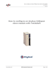
User’s Manual and SCPI Programming Guide
Where to Find it - Online and Printed Information:
System installation (hardware/software)............. VXIbus Configuration Guide*
Agilent VIC (VXI installation software)*
Module configuration and wiring........................ This Manual
SCPI programming.............................................. This Manual
SCPI example programs...................................... This Manual
SCPI command reference ................................... This Manual
Register-Based Programming ............................. This Manual
VXIplug&play programming ............................. VXIplug&play Online Help
VXIplug&play example programs...................... VXIplug&play Online Help
VXIplug&play function reference ...................... VXIplug&play Online Help
Soft Front Panel information............................... VXIplug&play Online Help
VISA language information ................................ Agilent VISA User’s Guide
Agilent VEE programming information ............. Agilent VEE User’s Manual
*Supplied with Agilent Command Modules, Embedded Controllers, and VXLink.
*E1418-90002*
Manual Part Number: E1418-90002
Printed in Malaysia E0706
Contents
Agilent E1418A User’s Manual
Warranty . . . . . . . . . .
Safety Symbols . . . . . .
WARNINGS . . . . . . . .
Declaration of Conformity .
User Notes . . . . . . . . .
.
.
.
.
.
.
.
.
.
.
.
.
.
.
.
.
.
.
.
.
.
.
.
.
.
.
.
.
.
.
.
.
.
.
.
.
.
.
.
.
.
.
.
.
.
.
.
.
.
.
.
.
.
.
.
.
.
.
.
.
.
.
.
.
.
.
.
.
.
.
.
.
.
.
.
.
.
.
.
.
.
.
.
.
.
.
.
.
.
.
.
.
.
.
.
.
.
.
.
.
.
.
.
.
.
.
.
.
.
.
.
.
.
.
.
.
.
.
.
.
.
.
.
.
.
.
.
.
.
.
.
.
.
.
.
.
.
.
.
.
.
.
.
.
.
.
.
.
.
.
.
.
.
.
.
.
.
.
.
.
7
8
8
9
10
Chapter 1. Module Setup and Installation . . . . . . . . . . . . . . . . . . . . . . . . . . . 13
Using This Chapter . . . . . . . . . . . . . .
Module Description . . . . . . . . . . . . . .
Ordering Options . . . . . . . . . . . . .
Field Kits . . . . . . . . . . . . . . . . .
Terminal Modules . . . . . . . . . . . .
Functional Description . . . . . . . . . . . . .
Front Panel Connectors . . . . . . . . . . . .
Setting the Logical Address Switch . . . . . .
Module Installation . . . . . . . . . . . . . .
Installation in a Mainframe . . . . . . . .
Terminal Modules . . . . . . . . . . . . . . .
Screw-Type Terminal Module (Standard)
Wiring the Terminal Module . . . . . . . . .
Attaching the Terminal Module . . . . . . . .
Removing the Terminal Module . . . . . . . .
Terminal Module Options . . . . . . . . . . .
Option A3E . . . . . . . . . . . . . . . .
Option A3H . . . . . . . . . . . . . . . .
Option 135 . . . . . . . . . . . . . . . .
Terminal Module Connectors . . . . . . . . .
Configuring the Terminal Module . . . . . . .
P/J Jumper . . . . . . . . . . . . . . . . .
V/I Jumper . . . . . . . . . . . . . . . .
Terminal Module Connections . . . . . . . .
Voltage and Current Output Connections
Combining Channels . . . . . . . . . . .
Connecting an External Trigger Source .
Using the CAL Output Terminals . . . .
Initial Operation . . . . . . . . . . . . . . . .
Device Driver . . . . . . . . . . . . . . .
Module Identification . . . . . . . . . . .
.
.
.
.
.
.
.
.
.
.
.
.
.
.
.
.
.
.
.
.
.
.
.
.
.
.
.
.
.
.
.
.
.
.
.
.
.
.
.
.
.
.
.
.
.
.
.
.
.
.
.
.
.
.
.
.
.
.
.
.
.
.
.
.
.
.
.
.
.
.
.
.
.
.
.
.
.
.
.
.
.
.
.
.
.
.
.
.
.
.
.
.
.
.
.
.
.
.
.
.
.
.
.
.
.
.
.
.
.
.
.
.
.
.
.
.
.
.
.
.
.
.
.
.
.
.
.
.
.
.
.
.
.
.
.
.
.
.
.
.
.
.
.
.
.
.
.
.
.
.
.
.
.
.
.
.
.
.
.
.
.
.
.
.
.
.
.
.
.
.
.
.
.
.
.
.
.
.
.
.
.
.
.
.
.
.
.
.
.
.
.
.
.
.
.
.
.
.
.
.
.
.
.
.
.
.
.
.
.
.
.
.
.
.
.
.
.
.
.
.
.
.
.
.
.
.
.
.
.
.
.
.
.
.
.
.
.
.
.
.
.
.
.
.
.
.
.
.
.
.
.
.
.
.
.
.
.
.
.
.
.
.
.
.
.
.
.
.
.
.
.
.
.
.
.
.
.
.
.
.
.
.
.
.
.
.
.
.
.
.
.
.
.
.
.
.
.
.
.
.
.
.
.
.
.
.
.
.
.
.
.
.
.
.
.
.
.
.
.
.
.
.
.
.
.
.
.
.
.
.
.
.
.
.
.
.
.
.
.
.
.
.
.
.
.
.
.
.
.
.
.
.
.
.
.
.
.
.
.
.
.
.
.
.
.
.
.
.
.
.
.
.
.
.
.
.
.
.
.
.
.
.
.
.
.
.
.
.
.
.
.
.
.
.
.
.
.
.
.
.
.
.
.
.
.
.
.
.
.
.
.
.
.
.
.
.
.
.
.
.
.
.
.
.
.
.
.
.
.
.
.
.
.
.
.
.
.
.
.
.
.
.
.
.
.
.
.
.
.
.
.
.
.
.
.
.
.
.
.
.
.
.
.
.
.
.
.
.
.
.
.
.
.
.
.
.
.
.
.
.
.
.
.
.
.
.
.
.
.
.
.
.
.
.
.
.
.
.
.
.
.
.
.
.
.
.
.
.
.
.
.
.
.
.
.
.
.
.
.
.
.
.
.
.
.
.
.
.
.
.
.
.
.
.
.
.
.
.
.
.
.
.
.
.
.
.
.
.
.
.
.
.
.
.
.
.
.
.
.
.
.
.
.
.
.
.
.
.
.
.
.
.
.
.
.
.
.
.
.
.
.
.
.
.
.
.
.
.
.
.
.
.
.
.
.
.
.
.
.
.
.
.
.
.
.
.
.
.
.
.
.
.
.
.
.
.
.
.
.
.
.
.
.
.
.
.
.
.
.
.
.
.
.
.
.
.
.
.
.
.
.
.
.
.
.
.
.
.
.
.
.
.
.
.
.
.
.
.
.
.
.
.
.
.
.
.
.
.
.
.
.
.
.
.
.
.
.
.
.
.
.
.
13
13
15
15
15
16
18
19
20
20
22
22
23
25
26
27
27
29
29
30
31
31
31
33
33
34
35
36
37
37
38
Agilent E1418A User’s Manual Contents
1
Chapter 2. Programming Examples . . . . . . . . . . . . . . . . . . . . . . . . . . . . . . 39
Using This Chapter . . . . . . . . . . . . . . . . .
Program Examples . . . . . . . . . . . . . . .
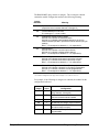
Querying Module Identification and Configuration .
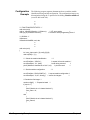
Configuration Example . . . . . . . . . . . . .
APPLy Output . . . . . . . . . . . . . . . . . . . .
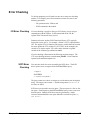
Error Checking . . . . . . . . . . . . . . . . . . . .
I/O Error Checking . . . . . . . . . . . . . . .
SCPI Error Checking . . . . . . . . . . . . . .
SOURce Output . . . . . . . . . . . . . . . . . . .
Setting the Output Mode . . . . . . . . . . . . . . .
Controlling the Output Relay . . . . . . . . . . . .
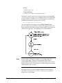
Triggering . . . . . . . . . . . . . . . . . . . . . .
Using *OPC? . . . . . . . . . . . . . . . . . . . .
Combining Output Channels . . . . . . . . . . . .
.
.
.
.
.
.
.
.
.
.
.
.
.
.
.
.
.
.
.
.
.
.
.
.
.
.
.
.
.
.
.
.
.
.
.
.
.
.
.
.
.
.
.
.
.
.
.
.
.
.
.
.
.
.
.
.
.
.
.
.
.
.
.
.
.
.
.
.
.
.
.
.
.
.
.
.
.
.
.
.
.
.
.
.
.
.
.
.
.
.
.
.
.
.
.
.
.
.
.
.
.
.
.
.
.
.
.
.
.
.
.
.
.
.
.
.
.
.
.
.
.
.
.
.
.
.
.
.
.
.
.
.
.
.
.
.
.
.
.
.
.
.
.
.
.
.
.
.
.
.
.
.
.
.
.
.
.
.
.
.
.
.
.
.
.
.
.
.
.
.
.
.
.
.
.
.
.
.
.
.
.
.
.
.
.
.
.
.
.
.
.
.
.
.
.
.
.
.
.
.
.
.
.
.
.
.
.
.
.
.
.
.
.
.
.
.
.
.
.
.
.
.
.
.
.
.
.
.
.
.
.
.
.
.
.
.
.
.
.
.
.
.
.
.
.
.
.
.
.
.
.
.
.
.
.
.
.
.
.
.
.
.
.
.
.
.
39
39
40
42
45
47
47
47
50
52
53
54
56
57
Chapter 3. Agilent E1418A SCPI Command Reference . . . . . . . . . . . . . . . . . . . 59
Using This Chapter . . . . . . . . . . . . . . . .
Command Types . . . . . . . . . . . . . . . . . .
Common Command Format . . . . . . . . .
SCPI Command Format . . . . . . . . . . . . . .
Linking Commands . . . . . . . . . . . . . .
SCPI Command Reference . . . . . . . . . . . .
ABORt . . . . . . . . . . . . . . . . . . . . . . .
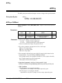
APPLy . . . . . . . . . . . . . . . . . . . . . . .
APPLyn:CURRent . . . . . . . . . . . . . .
APPLyn:VOLTage . . . . . . . . . . . . . .
CALibration . . . . . . . . . . . . . . . . . . . .
CALibration:CONDition? . . . . . . . . . .
CALibration:CONFigure:RESistance? . . . .
CALibration:RESet . . . . . . . . . . . . . .
CALibration:STORe . . . . . . . . . . . . .
CALibration:TEST? . . . . . . . . . . . . .
CALibration:VALue:RESistance . . . . . . .
CALibrationn:CONFigure:CURRent? . . . .
CALibrationn:CONFigure:VOLTage? . . . .
CALibrationn:VALue:CURRent? . . . . . .
CALibrationn:VALue:VOLTage? . . . . . .
DIAGnostic . . . . . . . . . . . . . . . . . . . .
DIAGnostic:CALibration:OUTPut[:MODE]
DIAGnostic:CALibration:OUTPut[:MODE]?
DIAGnostic:CONFigure? . . . . . . . . . . .
DIAGnostic:OUTPut:ALL[:STATe] . . . . .
DIAGnostic:SOURcen:FUNCtion:MODE . .
DIAGnostic:TRIGgered? . . . . . . . . . . .
INITiate . . . . . . . . . . . . . . . . . . . . . .
INITiate[:IMMediate] . . . . . . . . . . . . .
2
Agilent E1418A User’s Manual Contents
.
.
.
.
.
.
.
.
.
.
.
.
.
.
.
.
.
.
.
.
.
.
.
.
.
.
.
.
.
.
.
.
.
.
.
.
.
.
.
.
.
.
.
.
.
.
.
.
.
.
.
.
.
.
.
.
.
.
.
.
.
.
.
.
.
.
.
.
.
.
.
.
.
.
.
.
.
.
.
.
.
.
.
.
.
.
.
.
.
.
.
.
.
.
.
.
.
.
.
.
.
.
.
.
.
.
.
.
.
.
.
.
.
.
.
.
.
.
.
.
.
.
.
.
.
.
.
.
.
.
.
.
.
.
.
.
.
.
.
.
.
.
.
.
.
.
.
.
.
.
.
.
.
.
.
.
.
.
.
.
.
.
.
.
.
.
.
.
.
.
.
.
.
.
.
.
.
.
.
.
.
.
.
.
.
.
.
.
.
.
.
.
.
.
.
.
.
.
.
.
.
.
.
.
.
.
.
.
.
.
.
.
.
.
.
.
.
.
.
.
.
.
.
.
.
.
.
.
.
.
.
.
.
.
.
.
.
.
.
.
.
.
.
.
.
.
.
.
.
.
.
.
.
.
.
.
.
.
.
.
.
.
.
.
.
.
.
.
.
.
.
.
.
.
.
.
.
.
.
.
.
.
.
.
.
.
.
.
.
.
.
.
.
.
.
.
.
.
.
.
.
.
.
.
.
.
.
.
.
.
.
.
.
.
.
.
.
.
.
.
.
.
.
.
.
.
.
.
.
.
.
.
.
.
.
.
.
.
.
.
.
.
.
.
.
.
.
.
.
.
.
.
.
.
.
.
.
.
.
.
.
.
.
.
.
.
.
.
.
.
.
.
.
.
.
.
.
.
.
.
.
.
.
.
.
.
.
.
.
.
.
.
.
.
.
.
.
.
.
.
.
.
.
.
.
.
.
.
.
.
.
.
.
.
.
.
.
.
.
.
.
.
.
.
.
.
.
.
.
.
.
.
.
.
.
.
.
.
.
.
.
.
.
.
.
.
.
.
.
.
.
.
.
.
.
.
.
.
.
.
.
.
.
.
.
.
.
.
.
.
.
.
.
.
.
.
.
.
.
.
.
.
.
.
.
.
.
.
.
.
.
.
.
.
.
.
.
.
.
.
.
.
.
.
.
.
.
.
.
.
.
.
.
.
.
.
.
.
.
.
.
.
.
.
.
.
.
.
.
.
.
.
.
.
.
.
.
.
.
.
.
.
.
.
.
.
.
.
.
.
.
.
.
.
.
.
.
.
.
.
.
.
.
.
.
.
.
.
.
.
.
.
.
.
.
.
.
.
.
.
.
.
.
.
.
.
.
.
.
.
.
.
.
.
.
.
.
.
.
.
59
59
59
60
62
62
63
64
64
65
66
67
68
68
69
69
70
71
72
73
74
76
76
77
77
78
78
79
80
80
Chapter 3. Agilent E1418A SCPI Command Reference (continued)
OUTPut . . . . . . . . . . . . . . . . . . . . . . . . . . . . .
OUTPut:TTLTrgn[:STATe] . . . . . . . . . . . . . . . .
OUTPut:TTLTrgn[:STATe]? . . . . . . . . . . . . . . . .
OUTPutn[:STATe] . . . . . . . . . . . . . . . . . . . . .
OUTPutn[:STATe]? . . . . . . . . . . . . . . . . . . . .
SOURce . . . . . . . . . . . . . . . . . . . . . . . . . . . . .
SOURcen:CURRent[:LEVel][:IMMediate][:AMPLitude]
SOURcen:CURRent[:LEVel][:IMMediate][:AMPLitude]?
SOURcen:CURRent[:LEVel]:TRIGgered[:AMPLitude] .
SOURcen:CURRent[:LEVel]:TRIGgered[:AMPLitude]? .
SOURcen:FUNCtion:MODE . . . . . . . . . . . . . . . .
SOURcen:FUNCtion:MODE? . . . . . . . . . . . . . . .
SOURcen:VOLTage[:LEVel][:IMMediate][:AMPLitude]
SOURcen:VOLTage[:LEVel][:IMMediate][:AMPLitude]?
SOURcen:VOLTage[:LEVel]:TRIGgered[:AMPLitude] .
SOURcen:VOLTage[:LEVel]:TRIGgered[:AMPLitude]? .
STATus . . . . . . . . . . . . . . . . . . . . . . . . . . . . .
STATus:OPERation:CONDition? . . . . . . . . . . . . .
STATus:OPERation:ENABle . . . . . . . . . . . . . . .
STATus:OPERation:ENABle? . . . . . . . . . . . . . . .
STATus:OPERation[:EVENt]? . . . . . . . . . . . . . . .
STATus:PRESet . . . . . . . . . . . . . . . . . . . . . .
STATus:QUEStionable:CONDition? . . . . . . . . . . .
STATus:QUEStionable:ENABle . . . . . . . . . . . . . .
STATus:QUEStionable:ENABle? . . . . . . . . . . . . .
STATus:QUEStionable[:EVENt]? . . . . . . . . . . . . .
SYSTem . . . . . . . . . . . . . . . . . . . . . . . . . . . . .
SYSTem:ERRor? . . . . . . . . . . . . . . . . . . . . . .
SYSTem:VERSion? . . . . . . . . . . . . . . . . . . . .
TEST . . . . . . . . . . . . . . . . . . . . . . . . . . . . . . .
TEST:NUMBer? . . . . . . . . . . . . . . . . . . . . . .
TEST:TST[:RESults]? . . . . . . . . . . . . . . . . . . .
*TST? . . . . . . . . . . . . . . . . . . . . . . . . . . . .
TRIGger . . . . . . . . . . . . . . . . . . . . . . . . . . . . .
TRIGger[:IMMediate] . . . . . . . . . . . . . . . . . . .
TRIGger:SOURce . . . . . . . . . . . . . . . . . . . . .
TRIGger:SOURce? . . . . . . . . . . . . . . . . . . . . .
IEEE-488.2 Common Command Quick Reference . . . . . . .
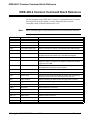
Agilent E1418A Command Quick Reference . . . . . . . . . .
.
.
.
.
.
.
.
.
.
.
.
.
.
.
.
.
.
.
.
.
.
.
.
.
.
.
.
.
.
.
.
.
.
.
.
.
.
.
.
.
.
.
.
.
.
.
.
.
.
.
.
.
.
.
.
.
.
.
.
.
.
.
.
.
.
.
.
.
.
.
.
.
.
.
.
.
.
.
.
.
.
.
.
.
.
.
.
.
.
.
.
.
.
.
.
.
.
.
.
.
.
.
.
.
.
.
.
.
.
.
.
.
.
.
.
.
.
.
.
.
.
.
.
.
.
.
.
.
.
.
.
.
.
.
.
.
.
.
.
.
.
.
.
.
.
.
.
.
.
.
.
.
.
.
.
.
.
.
.
.
.
.
.
.
.
.
.
.
.
.
.
.
.
.
.
.
.
.
.
.
.
.
.
.
.
.
.
.
.
.
.
.
.
.
.
.
.
.
.
.
.
.
.
.
.
.
.
.
.
.
.
.
.
.
.
.
.
.
.
.
.
.
.
.
.
.
.
.
.
.
.
.
.
.
.
.
.
.
.
.
.
.
.
.
.
.
.
.
.
.
.
.
.
.
.
.
.
.
.
.
.
.
.
.
.
.
.
.
.
.
.
.
.
.
.
.
.
.
.
.
.
.
.
.
.
.
.
.
.
.
.
.
.
.
.
.
.
.
.
.
.
.
.
.
.
.
.
.
.
.
.
.
.
.
.
.
.
.
.
.
.
.
.
.
.
.
.
.
.
.
.
.
.
.
.
.
.
.
.
.
.
.
.
.
.
.
.
.
.
.
.
.
.
.
.
.
.
.
.
.
.
.
.
.
.
.
.
.
.
.
.
.
.
.
.
.
.
.
.
.
.
.
.
.
.
.
.
.
.
.
.
.
.
.
.
.
.
.
.
.
.
.
.
.
.
.
.
.
.
.
.
.
.
.
.
.
.
.
.
.
.
.
.
.
.
.
.
.
.
.
.
.
.
.
.
.
.
.
.
.
.
.
.
.
.
.
.
.
.
.
.
.
.
.
.
.
.
.
.
.
.
.
.
.
.
.
.
.
.
.
.
.
.
.
.
.
.
.
.
.
.
.
.
.
.
.
.
.
.
.
.
.
.
.
.
.
.
.
.
.
.
.
.
.
.
.
.
81
81
82
82
83
84
85
86
87
88
89
90
91
92
93
94
95
96
96
97
97
97
98
98
99
99
100
100
100
101
101
102
103
104
104
105
105
106
107
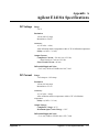
Appendix A. Agilent E1418A Specifications . . . . . . . . . . . . . . . . . . . . . . . . . . 111
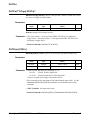
DC Voltage . . . . . .
DC Current . . . . . .
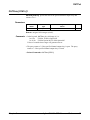
General Characteristics
Power Requirements .
Cooling Requirements
.
.
.
.
.
.
.
.
.
.
.
.
.
.
.
.
.
.
.
.
.
.
.
.
.
.
.
.
.
.
.
.
.
.
.
.
.
.
.
.
.
.
.
.
.
.
.
.
.
.
.
.
.
.
.
.
.
.
.
.
.
.
.
.
.
.
.
.
.
.
.
.
.
.
.
.
.
.
.
.
.
.
.
.
.
.
.
.
.
.
.
.
.
.
.
.
.
.
.
.
.
.
.
.
.
.
.
.
.
.
.
.
.
.
.
.
.
.
.
.
.
.
.
.
.
.
.
.
.
.
.
.
.
.
.
.
.
.
.
.
.
.
.
.
.
.
.
.
.
.
.
.
.
.
.
.
.
.
.
.
111
111
112
112
112
Agilent E1418A User’s Manual Contents
3
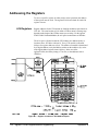
Appendix B. Agilent E1418A Register-Based Programming . . . . . . . . . . . . . . . . . 113
Addressing the Registers . . . . . . . . . . . . .
A16 Registers . . . . . . . . . . . . . . . . .
A24 Registers . . . . . . . . . . . . . . . . .
The Base Address . . . . . . . . . . . . . . .
Register Offset . . . . . . . . . . . . . . . .
Reset and Registers . . . . . . . . . . . . . . . .
Register Maps . . . . . . . . . . . . . . . . . . .
A16/A24 REGISTERS . . . . . . . . . . . .
A24 REGISTERS . . . . . . . . . . . . . . .
Register Descriptions . . . . . . . . . . . . . . .
Manufacturer ID Register . . . . . . . . . . .
Logical Address Register . . . . . . . . . . .
Device Type Register . . . . . . . . . . . . .
VXI Status/Control Register . . . . . . . . .
VXI Offset Register . . . . . . . . . . . . . .
Calibration Control Register . . . . . . . . .
Card Configuration Register . . . . . . . . .
Software Trigger Register . . . . . . . . . .
Trigger Control Register . . . . . . . . . . .
Interrupt Status Register . . . . . . . . . . .
Isolation Status Register . . . . . . . . . . .
Channel Program Jumper Register . . . . . .
Channel Trigger Register . . . . . . . . . . .
Channel Mode Register . . . . . . . . . . . .
Channel Relay Control Register . . . . . . .
Card Control Register . . . . . . . . . . . . .
Main_DAC Immediate Registers . . . . . . .
Main_DAC Triggered Registers . . . . . . .
Offset_DAC Registers . . . . . . . . . . . .
Gain_DAC Registers . . . . . . . . . . . . .
Undefined Registers . . . . . . . . . . . . .
Channel Voltage Offset Calibration Registers
Channel Voltage Gain Calibration Registers .
Channel Current Offset Calibration Registers
Channel Current Gain Calibration Registers .
Calibration Resistor Value Registers . . . . .
Voltage Calibration Status Register . . . . .
Current Calibration Status Register . . . . . .
Calibration Isolation Status Register . . . . .
Calibration Card Configuration Register . . .
Calibration Checksum Register . . . . . . . .
Module Serial Number Registers . . . . . . .
Register Example . . . . . . . . . . . . . . . . .
4
Agilent E1418A User’s Manual Contents
.
.
.
.
.
.
.
.
.
.
.
.
.
.
.
.
.
.
.
.
.
.
.
.
.
.
.
.
.
.
.
.
.
.
.
.
.
.
.
.
.
.
.
.
.
.
.
.
.
.
.
.
.
.
.
.
.
.
.
.
.
.
.
.
.
.
.
.
.
.
.
.
.
.
.
.
.
.
.
.
.
.
.
.
.
.
.
.
.
.
.
.
.
.
.
.
.
.
.
.
.
.
.
.
.
.
.
.
.
.
.
.
.
.
.
.
.
.
.
.
.
.
.
.
.
.
.
.
.
.
.
.
.
.
.
.
.
.
.
.
.
.
.
.
.
.
.
.
.
.
.
.
.
.
.
.
.
.
.
.
.
.
.
.
.
.
.
.
.
.
.
.
.
.
.
.
.
.
.
.
.
.
.
.
.
.
.
.
.
.
.
.
.
.
.
.
.
.
.
.
.
.
.
.
.
.
.
.
.
.
.
.
.
.
.
.
.
.
.
.
.
.
.
.
.
.
.
.
.
.
.
.
.
.
.
.
.
.
.
.
.
.
.
.
.
.
.
.
.
.
.
.
.
.
.
.
.
.
.
.
.
.
.
.
.
.
.
.
.
.
.
.
.
.
.
.
.
.
.
.
.
.
.
.
.
.
.
.
.
.
.
.
.
.
.
.
.
.
.
.
.
.
.
.
.
.
.
.
.
.
.
.
.
.
.
.
.
.
.
.
.
.
.
.
.
.
.
.
.
.
.
.
.
.
.
.
.
.
.
.
.
.
.
.
.
.
.
.
.
.
.
.
.
.
.
.
.
.
.
.
.
.
.
.
.
.
.
.
.
.
.
.
.
.
.
.
.
.
.
.
.
.
.
.
.
.
.
.
.
.
.
.
.
.
.
.
.
.
.
.
.
.
.
.
.
.
.
.
.
.
.
.
.
.
.
.
.
.
.
.
.
.
.
.
.
.
.
.
.
.
.
.
.
.
.
.
.
.
.
.
.
.
.
.
.
.
.
.
.
.
.
.
.
.
.
.
.
.
.
.
.
.
.
.
.
.
.
.
.
.
.
.
.
.
.
.
.
.
.
.
.
.
.
.
.
.
.
.
.
.
.
.
.
.
.
.
.
.
.
.
.
.
.
.
.
.
.
.
.
.
.
.
.
.
.
.
.
.
.
.
.
.
.
.
.
.
.
.
.
.
.
.
.
.
.
.
.
.
.
.
.
.
.
.
.
.
.
.
.
.
.
.
.
.
.
.
.
.
.
.
.
.
.
.
.
.
.
.
.
.
.
.
.
.
.
.
.
.
.
.
.
.
.
.
.
.
.
.
.
.
.
.
.
.
.
.
.
.
.
.
.
.
.
.
.
.
.
.
.
.
.
.
.
.
.
.
.
.
.
.
.
.
.
.
.
.
.
.
.
.
.
.
.
.
.
.
.
.
.
.
.
.
.
.
.
.
.
.
.
.
.
.
.
.
.
.
.
.
.
.
.
.
.
.
.
.
.
.
.
.
.
.
.
.
.
.
.
.
.
.
.
.
.
.
.
.
.
.
.
.
.
.
.
.
.
.
.
.
.
.
.
.
.
.
.
.
.
.
.
.
.
.
.
.
.
.
.
.
.
.
.
.
.
.
.
.
.
.
.
.
.
.
.
.
.
.
.
.
.
.
.
.
.
.
.
.
.
.
.
.
.
.
.
.
.
.
.
.
.
.
.
.
.
.
.
.
.
.
.
.
.
.
.
.
.
.
.
.
.
.
.
.
.
.
.
.
.
.
.
.
.
.
.
.
.
.
.
.
.
.
.
.
.
.
.
.
.
.
.
.
.
.
.
.
.
.
.
.
.
.
.
.
.
.
.
.
.
.
.
.
.
.
.
.
.
.
.
.
.
.
.
.
.
.
.
.
.
.
.
.
.
.
.
.
.
.
.
.
.
.
114
114
115
117
118
119
120
120
121
126
126
126
127
127
128
129
130
131
131
133
133
134
135
136
136
137
138
138
139
139
140
140
141
142
143
144
144
145
146
147
147
148
148
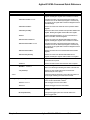
Appendix C. Agilent E1418A Error Messages . . . . . . . . . . . . . . . . . . . . . . . . . 151
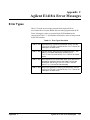
Error Types . . . . . . . . . . . . . . . . . . . . . . . . . . . . . . . . . . . . . . . . 151
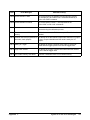
Error Messages . . . . . . . . . . . . . . . . . . . . . . . . . . . . . . . . . . . . . . 152
Appendix D. Voltage/Current Output Adjustment . . . . . . . . . . . . . . . . . . . . . . 155
Using This Appendix . . . . . . . . . . . . . . .
Calibration Constants and Non-Volatile Memory
Equipment Required . . . . . . . . . . . . . . . .
Making Connections . . . . . . . . . . . . . . . .
Adjustment Procedure . . . . . . . . . . . . . . .
Preparation . . . . . . . . . . . . . . . . . .
Voltage Adjustment . . . . . . . . . . . . . .
Current Adjustment . . . . . . . . . . . . . .
Storing the Adjustments . . . . . . . . . . .
Return the Module to Use . . . . . . . . . .
Example Program . . . . . . . . . . . . . . .
.
.
.
.
.
.
.
.
.
.
.
.
.
.
.
.
.
.
.
.
.
.
.
.
.
.
.
.
.
.
.
.
.
.
.
.
.
.
.
.
.
.
.
.
.
.
.
.
.
.
.
.
.
.
.
.
.
.
.
.
.
.
.
.
.
.
.
.
.
.
.
.
.
.
.
.
.
.
.
.
.
.
.
.
.
.
.
.
.
.
.
.
.
.
.
.
.
.
.
.
.
.
.
.
.
.
.
.
.
.
.
.
.
.
.
.
.
.
.
.
.
.
.
.
.
.
.
.
.
.
.
.
.
.
.
.
.
.
.
.
.
.
.
.
.
.
.
.
.
.
.
.
.
.
.
.
.
.
.
.
.
.
.
.
.
.
.
.
.
.
.
.
.
.
.
.
.
.
.
.
.
.
.
.
.
.
.
.
.
.
.
.
.
.
.
.
.
.
.
.
.
.
.
.
.
.
.
.
.
.
.
.
.
.
.
.
.
.
.
.
155
156
156
156
157
157
158
160
163
163
163
Appendix E. Configuration and Disassembly . . . . . . . . . . . . . . . . . . . . . . . . . 167
Using This Appendix . . . . . . . . . . . . . . . . .
Configuration . . . . . . . . . . . . . . . . . . . . .
Checking Configuration . . . . . . . . . . . . .
Changing Configuration . . . . . . . . . . . . .
Adding 8 Channels . . . . . . . . . . . . . . . .
Installing Isolated/Non-Isolated Plug-on Modules
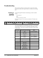
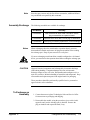
Troubleshooting . . . . . . . . . . . . . . . . . . . .
Isolating an Assembly (Self-Test) . . . . . . . .
Assembly Exchange . . . . . . . . . . . . . . .
To Exchange an Assembly . . . . . . . . . . . .
.
.
.
.
.
.
.
.
.
.
.
.
.
.
.
.
.
.
.
.
.
.
.
.
.
.
.
.
.
.
.
.
.
.
.
.
.
.
.
.
.
.
.
.
.
.
.
.
.
.
.
.
.
.
.
.
.
.
.
.
.
.
.
.
.
.
.
.
.
.
.
.
.
.
.
.
.
.
.
.
.
.
.
.
.
.
.
.
.
.
.
.
.
.
.
.
.
.
.
.
.
.
.
.
.
.
.
.
.
.
.
.
.
.
.
.
.
.
.
.
.
.
.
.
.
.
.
.
.
.
.
.
.
.
.
.
.
.
.
.
.
.
.
.
.
.
.
.
.
.
.
.
.
.
.
.
.
.
.
.
.
.
.
.
.
.
.
.
.
.
.
.
.
.
.
.
.
.
.
.
167
167
167
168
169
172
174
174
175
175
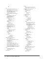
Index. . . . . . . . . . . . . . . . . . . . . . . . . . . . . . . . . . . . . . . . . . . . . . . . 177
Agilent E1418A User’s Manual Contents
5
Notes
6
Agilent E1418A User’s Manual Contents
Certification
Agilent Technologies certifies that this product met its published specifications at the time of shipment from the factory. Agilent
Technologies further certifies that its calibration measurements are traceable to the United States National Institute of Standards and
Technology (formerly National Bureau of Standards), to the extent allowed by that organization’s calibration facility, and to the calibration
facilities of other International Standards Organization members.
Warranty
This Agilent Technologies product is warranted against defects in materials and workmanship for a period of one (1) year from date of
shipment. Duration and conditions of warranty for this product may be superseded when the product is integrated into (becomes a part
of) other Agilent products. During the warranty period, Agilent Technologies will, at its option, either repair or replace products which
prove to be defective.
For warranty service or repair, this product must be returned to a service facility designated by Agilent Technologies. Buyer shall prepay
shipping charges to Agilent and Agilent shall pay shipping charges to return the product to Buyer. However, Buyer shall pay all shipping
charges, duties, and taxes for products returned to Agilent from another country.
Agilent warrants that its software and firmware designated by Agilent for use with a product will execute its programming instructions
when properly installed on that product. Agilent does not warrant that the operation of the product, or software, or firmware will be
uninterrupted or error free.
Limitation Of Warranty
The foregoing warranty shall not apply to defects resulting from improper or inadequate maintenance by Buyer, Buyer-supplied products
or interfacing, unauthorized modification or misuse, operation outside of the environmental specifications for the product, or improper site
preparation or maintenance.
The design and implementation of any circuit on this product is the sole responsibility of the Buyer. Agilent does not warrant the Buyer’s
circuitry or malfunctions of Agilent products that result from the Buyer’s circuitry. In addition, Agilent does not warrant any damage that
occurs as a result of the Buyer’s circuit or any defects that result from Buyer-supplied products.
NO OTHER WARRANTY IS EXPRESSED OR IMPLIED. Agilent SPECIFICALLY DISCLAIMS THE IMPLIED WARRANTIES
OF MERCHANTABILITY AND FITNESS FOR A PARTICULAR PURPOSE.
Exclusive Remedies
THE REMEDIES PROVIDED HEREIN ARE BUYER’S SOLE AND EXCLUSIVE REMEDIES. Agilent SHALL NOT BE LIABLE
FOR ANY DIRECT, INDIRECT, SPECIAL, INCIDENTAL, OR CONSEQUENTIAL DAMAGES, WHETHER BASED ON CONTRACT, TORT, OR ANY OTHER LEGAL THEORY.
Notice
The information contained in this document is subject to change without notice. Agilent Technologies MAKES NO WARRANTY OF
ANY KIND WITH REGARD TO THIS MATERIAL, INCLUDING, BUT NOT LIMITED TO, THE IMPLIED WARRANTIES OF
MERCHANTABILITY AND FITNESS FOR A PARTICULAR PURPOSE. Agilent shall not be liable for errors contained herein or for
incidental or consequential damages in connection with the furnishing, performance or use of this material. This document contains
proprietary information which is protected by copyright. All rights are reserved. No part of this document may be photocopied, reproduced,
or translated to another language without the prior written consent of Agilent Technologies, Inc. Agilent assumes no responsibility for the
use or reliability of its software on equipment that is not furnished by Agilent.
U.S. Government Restricted Rights
The Software and Documentation have been developed entirely at private expense. They are delivered and licensed as "commercial
computer software" as defined in DFARS 252.227- 7013 (Oct 1988), DFARS 252.211-7015 (May 1991) or DFARS 252.227-7014 (Jun
1995), as a "commercial item" as defined in FAR 2.101(a), or as "Restricted computer software" as defined in FAR 52.227-19 (Jun 1987)(or
any equivalent agency regulation or contract clause), whichever is applicable. You have only those rights provided for such Software and
Documentation by the applicable FAR or DFARS clause or the Agilent standard software agreement for the product involved.
Agilent E1418A 8/16 Channel D/A Converter Module User’s Manual
Edition 2 Rev 2
Copyright © 1996-2006 Agilent Technologies, Inc. All Rights Reserved.
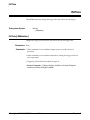
Agilent E1418A 8/16 D/A Converter Module User’s Manual
7
Printing History
The Printing History shown below lists all Editions and Updates of this manual and the printing date(s). The first printing of the manual
is Edition 1. The Edition number increments by 1 whenever the manual is revised. Updates, which are issued between Editions, contain
replacement pages to correct the current Edition of the manual. Updates are numbered sequentially starting with Update 1. When a new
Edition is created, it contains all the Update information for the previous Edition. Each new Edition or Update also includes a revised copy
of this printing history page. Many product updates or revisions do not require manual changes and, conversely, manual corrections may
be done without accompanying product changes. Therefore, do not expect a one-to-one correspondence between product updates and
manual updates.
Edition 1 (Part Number E1418-90001). . . . . . . . . . . . . . . . . . . . . . October 1995
Edition 2 (Part Number E1418-90002). . . . . . . . . . . . . . . . . . . . . . October 1996
Edition 2 Rev 2 (Part Number E1418-90002) . . . . . . . . . . . . . . . . . . . July 2006
Safety Symbols
Instruction manual symbol affixed to product.
Indicates that the user must refer to the manual for specific WARNING or CAUTION
information to avoid personal injury or damage to the product.
Alternating current (AC).
Direct current (DC).
Indicates hazardous voltages.
Indicates the field wiring terminal that must
be connected to earth ground before operating
the equipment—protects against electrical
shock in case of fault.
or
Frame or chassis ground terminal—typically
connects to the equipment’s metal frame.
WARNING
CAUTION
Calls attention to a procedure, practice, or condition that could cause bodily injury or death.
Calls attention to a procedure, practice, or condition that could possibly cause damage to
equipment or permanent loss of data.
WARNINGS
The following general safety precautions must be observed during all phases of operation, service, and repair of this product.
Failure to comply with these precautions or with specific warnings elsewhere in this manual violates safety standards of design,
manufacture, and intended use of the product. Agilent Technologies assumes no liability for the customer’s failure to comply with
these requirements.
Ground the equipment: For Safety Class 1 equipment (equipment having a protective earth terminal), an uninterruptible safety earth
ground must be provided from the mains power source to the product input wiring terminals or supplied power cable.
DO NOT operate the product in an explosive atmosphere or in the presence of flammable gases or fumes.
For continued protection against fire, replace the line fuse(s) only with fuse(s) of the same voltage and current rating and type.
DO NOT use repaired fuses or short-circuited fuse holders.
Keep away from live circuits: Operating personnel must not remove equipment covers or shields. Procedures involving the removal of
covers or shields are for use by service-trained personnel only. Under certain conditions, dangerous voltages may exist even with the
equipment switched off. To avoid dangerous electrical shock, DO NOT perform procedures involving cover or shield removal unless you
are qualified to do so.
DO NOT operate damaged equipment: Whenever it is possible that the safety protection features built into this product have been
impaired, either through physical damage, excessive moisture, or any other reason, REMOVE POWER and do not use the product until
safe operation can be verified by service-trained personnel. If necessary, return the product to an Agilent Technologies Sales and Service
Office for service and repair to ensure that safety features are maintained.
DO NOT service or adjust alone: Do not attempt internal service or adjustment unless another person, capable of rendering first aid and
resuscitation, is present.
DO NOT substitute parts or modify equipment: Because of the danger of introducing additional hazards, do not install substitute parts
or perform any unauthorized modification to the product. Return the product to an Agilent Technologies Sales and Service Office for
service and repair to ensure that safety features are maintained.
8
Agilent E1418A 8/16 D/A Converter Module User’s Manual
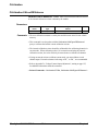
DECLARATION OF CONFORMITY
According to ISO/IEC Guide 22 and CEN/CENELEC EN 45014
Manufacturer’s Name:
Manufacturer’s Address:
Agilent Technologies, Incorporated
815 – 14th St. SW
Loveland, Colorado 80537
USA
Declares, that the product
Product Name:
Model Number:
Product Options:
16 Channel 16 Bit D/A Converter
E1418A, E1523A, E1524A, E1525A
This declaration covers all options of the above product(s).
Conforms with the following European Directives:
The product herewith complies with the requirements of the Low Voltage Directive 73/23/EEC and the EMC Directive 89/336/EEC
(including 93/68/EEC) and carries the CE Marking accordingly.
Conforms with the following product standards:
EMC
Standard
Limit
IEC 61326-1:1997+A1:1998 / EN 61326-1:1997+A1:1998
CISPR 11:1990 / EN 55011:1991
IEC 61000-4-2:1995+A1:1998 / EN 61000-4-2:1995
IEC 61000-4-3:1995 / EN 61000-4-3:1995
IEC 61000-4-4:1995 / EN 61000-4-4:1995
IEC 61000-4-5:1995 / EN 61000-4-5:1995
IEC 61000-4-6:1996 / EN 61000-4-6:1996
IEC 61000-4-11:1994 / EN 61000-4-11:1994
Group 1 Class A
4kV CD, 8kV AD
3 V/m, 80-1000 MHz
0.5kV signal lines, 1kV power lines
0.5 kV line-line, 1 kV line-ground
3V, 0.15-80 MHz I cycle, 100%
Dips: 30% 10ms; 60% 100ms
Interrupt > 95%@5000ms
Canada: ICES-001:1998
Australia/New Zealand: AS/NZS 2064.1
The product was tested in a typical configuration with Agilent Technologies test systems.
IEC 61010-1:1990+A1:1992+A2:1995 / EN 61010-1:1993+A2:1995
Canada: CSA C22.2 No. 1010.1:1992
UL 3111-1: 1994
Safety
20 March 2003
Date
Ray Corson
Product Regulations Program Manager
For further information, please contact your local Agilent Technologies sales office, agent or distributor.
Agilent E1418A 8/16 D/A Converter Module User’s Manual
9
Notes
10
Agilent E1418A 8/16 D/A Converter Module User’s Manual
Notes
Agilent E1418A 8/16 D/A Converter Module User’s Manual
11
Notes
12
Agilent E1418A 8/16 D/A Converter Module User’s Manual
Chapter 1
Module Setup and Installation
Using This Chapter
This chapter provides general module information and tasks you must
perform to install and prepare your module. A procedure to verify your
installation is also given. The chapter is divided into the following sections:
•
•
•
•
•
•
•
•
•
•
•
•
•
•
Module Description . . . . . . . . . . . . . . . . . . . . . . . . . . . . . . . .
Functional Description. . . . . . . . . . . . . . . . . . . . . . . . . . . . . .
Front Panel Connectors . . . . . . . . . . . . . . . . . . . . . . . . . . . . .
Setting the Logical Address Switch. . . . . . . . . . . . . . . . . . . .
Module Installation . . . . . . . . . . . . . . . . . . . . . . . . . . . . . . . .
Terminal Modules . . . . . . . . . . . . . . . . . . . . . . . . . . . . . . . . .
Wiring the Terminal Module . . . . . . . . . . . . . . . . . . . . . . . . .
Attaching the Terminal Module. . . . . . . . . . . . . . . . . . . . . . .
Removing the Terminal Module . . . . . . . . . . . . . . . . . . . . . .
Terminal Module Options . . . . . . . . . . . . . . . . . . . . . . . . . . .
Terminal Module Connectors . . . . . . . . . . . . . . . . . . . . . . . .
Configuring the Terminal Module. . . . . . . . . . . . . . . . . . . . .
Terminal Module Connections . . . . . . . . . . . . . . . . . . . . . . .
Initial Operation . . . . . . . . . . . . . . . . . . . . . . . . . . . . . . . . . . .
Page 13
Page 16
Page 18
Page 19
Page 20
Page 22
Page 23
Page 25
Page 26
Page 27
Page 30
Page 31
Page 33
Page 37
Module Description
The Agilent E1418A is an 8 or 16 channel digital-to-analog converter
module for use in a VXIbus C-size mainframe. The module is a
register-based device. The module can be programmed via direct register
access or, with the appropriate driver, by high level commands. This
manual describes programming the module using SCPI (Standard
Commands for Programmable Instruments) and the SCPI driver.
Each Agilent E1418A module is a unique instrument having its own output
buffer and error queue. Multiple modules cannot be combined into a single
instrument.
Each channel can be configured to either voltage or current output mode.
When configured for voltage output, voltages in the range of -16.0 to
+16.0 Volts can be set. When configured for current output, current in the
range of -0.02 to + 0.02 Amps can be set. The channel output mode can be
programmatically set, or, can be forced to either voltage or current by
mechanical jumpers on the terminal module.
Chapter 1
Module Setup and Installation
13
Each output channel is individually configurable to be either an isolated
output or a non-isolated output. Channel configuration to isolated or
non-isolated is made by individual plug-on modules for each channel.
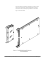
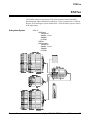
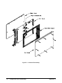
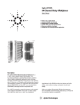
Figure 1-1 shows the module.
Figure 1-1. The E1418A 8/16-Channel D/A Converter
with Terminal Module
14
Module Setup and Installation
Chapter 1
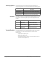
Ordering Options
The Agilent E1418A may be ordered from Agilent Technologies in a
variety of configurations. As ordered, the module has the following options:
Description
Field Kits
E1418A
8-Channel D/A Converter with Non-Isolated Outputs
E1418A Option 001
16-Channel D/A Converter with Non-Isolated Outputs
E1418A Option 002
8-Channel D/A Converter with Isolated Outputs
E1418A Option 003
16-Channel D/A Converter with Isolated Outputs
The module can also be user configured as described beginning on page 167
of this manual. The following field expansion and configuration kits are
available:
Description
Terminal Modules
Use
E1523A
Single Channel Isolated
plug-on module
To change a single channel from
non-isolated to isolated output.
E1524A
Expansion kit, 8-Channel To add 8 additional non-isolated
Non-Isolated Outputs
channels to an existing 8-channel
module.
E1525A
Expansion kit, 8-Channel To add 8 additional isolated channels to
Isolated Outputs
an existing 8-channel module.
The standard Agilent E1418A Terminal Module provides screw terminals
for connections. Two other terminal options are available with the
Agilent E1418A:
– Crimp and Insert (Option A3E)
– Ribbon Cable (Option A3H)
– Terminal Module Housing without a terminal module PC board or
connectors included (Option 135)
Chapter 1
Module Setup and Installation
15
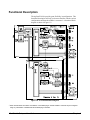
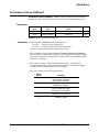
Functional Description
The Agilent E1418A provides great flexibility in configuration. This
functional description will help you become familiar with the various
configurations and how the module is structured. A functional block
diagram is shown in Figure 1-2.
Figure 1-2. A Functional Block Diagram
* Each channel MUST have either an isolated or non-isolated plug-on module installed. Channels may be configured
using any combination of Isolated and Non-Isolated plug-on modules.
16
Module Setup and Installation
Chapter 1
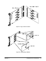
As shown, there are four major assemblies that make up an Agilent E1418A:
– Channels 1 through 8 main board and VXIbus backplane circuitry.
– Channels 9 through 16 expansion board.
– Isolated or Non-isolated plug-on modules.
– Terminal Module.
Channels 1–8 main board and VXIbus backplane circuitry.
This assembly contains all the VXIbus interface and decoding circuitry.
Isolated and Non-Isolated plug-on modules for channels 1–8 connect to this
assembly. The panel connectors for the terminal module are also mounted
on this assembly.
The optional Channels 9–16 expansion board is electrically connected and
mechanically mounted to the main board. Isolated and Non-Isolated
plug-on modules for channels 9–16 connect to this assembly.
Isolated or Non-isolated plug-on modules are required for every channel.
Eight plug-on modules mount to the main board and 8 plug-on modules
mount to the expansion board. Any combination of isolated or non-isolated
plug-on modules may be used, but every channel must have a plug-on
module installed.
The Terminal Module shown in Figure 1-2 is the standard screw-type
terminal module. This module provides screw connections for each channel
output, the calibration connections, and the external trigger in connections.
This module also contains two jumpers for each channel; one, called the P/J
Jumper, to enable or disable VXIbus programming of the channel mode
(either voltage or current) and one, called the V/I Jumper, to set the channel
mode when the P/J Jumper is in the Jumper position.
Chapter 1
Module Setup and Installation
17
Front Panel Connectors
Figure 1-3 shows the connections at the front panel connectors of the main
module.
Figure 1-3. E1418A Front Panel Connector Pinout
18
Module Setup and Installation
Chapter 1
Setting the Logical Address Switch
Figure 1-4 shows the logical address switch location and setting. The logical
address switch factory setting is 72. Valid addresses range from 1 to 255.
When used with an Agilent Command Module the factory set address of
decimal 72 results in a module address of 9 (72 divided by 8). The module
address is used as a secondary address when using GPIB and a Command
Module. For example, the module address may be 7 09 09, where 7 is the
GPIB interface address, 09 is the command module address, and 09 is the
Agilent E1418A address.
The Agilent E1418A supports dynamic address configuration. When you
set the logical address to 255, the resource manager sets the logical address
programmatically.
Note
When using an Agilent C-size mainframe with the Agilent E1405/E1406
Command Modules, the logical address setting must be a multiple of 8.
Figure 1-4. Setting the Logical Address
Chapter 1
Module Setup and Installation
19
Module Installation
To install the module:
1. Verify the position of the CAL Store Enable Jumper for your
application. The Jumper, as shipped, is in the CAL position. In this
position, a calibration may be performed and the results stored in
non-volatile memory. In the Secured position, a calibration may be
performed, but may NOT be stored in non-volatile memory. This
jumper is described in more detail on page 157.
2. Verify or set the logical address switch as shown in Figure 1-4.
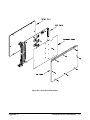
3. Install the module in a mainframe as shown in Figure 1-5.
Installation in a
Mainframe
The Agilent E1418A may be installed in any slot (except slot 0) in a C-size
VXIbus mainframe. To install in a mainframe:
1. Set the extraction levers out. Slide the module into any slot (except
slot 0) until the backplane connectors touch.
2. Seat the module by moving the levers toward each other.
3. Tighten the top and bottom screws to secure the module in the
mainframe.
Figure 1-5. Installing the E1418A in a VXIbus Mainframe
20
Module Setup and Installation
Chapter 1
To Remove a Module:
To remove a module from a mainframe:
1. Remove any terminal modules.
2. Loosen the top and bottom screws securing the module in the
mainframe.
3. Move the extraction levers away from each other. As the levers are
moved, the module will detach from the backplane connectors.
4. Slide the module out.
Note
Chapter 1
The extraction levers will not seat and unseat the backplane connectors on
older Agilent VXIbus mainframes and non-Agilent mainframes. You must
manually seat the connectors by pushing the module into the mainframe
until the front panel is flush with the front of the mainframe. The extraction
levers may be used to guide or remove the module.
Module Setup and Installation
21
Terminal Modules
Four terminal modules are available for the Agilent E1418A; a screw-type,
a crimp-and-insert type, a ribbon cable type, and an empty terminal housing
(without a PC board or connectors).
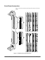
Screw-Type
Terminal Module
(Standard)
The standard terminal module uses screw-type terminals to make
connections. Figure 1-6 may be photocopied and used for wiring layout.
Figure 1-6. Screw-Type Terminal Module Layout
22
Module Setup and Installation
Chapter 1
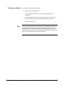
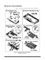
Wiring the Terminal Module
Figure 1-7 shows how to open and wire the E1418A terminal module.
Figure 1-7. Wiring the E1418A Terminal Module
(continued on next page)
Chapter 1
Module Setup and Installation
23
Figure 1-7. Wiring the E1418A Terminal Module
(continued from previous page)
24
Module Setup and Installation
Chapter 1
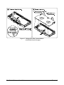
Attaching the Terminal Module
Figure 1-8 shows how to attach the E1418A terminal module.
Figure 1-8. Attaching the E1418A Terminal Module
Chapter 1
Module Setup and Installation
25
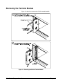
Removing the Terminal Module
Figure 1-9 shows how to remove the E1418A terminal module.
Figure 1-9. Removing the E1418A Terminal Module
26
Module Setup and Installation
Chapter 1
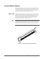
Terminal Module Options
Besides the standard screw-type terminal module, the Agilent E1418A can
be ordered with the following two options. One option (A3E) provides
crimp-and-insert connectors and terminal housing. The other option (A3H)
provides a ribbon cable connector and terminal housing.
Option A3E
Note
Agilent E1418A Option A3E can be ordered if a crimp-and-insert terminal
module is desired. This allows you to crimp connectors onto wires which
are then inserted directly into the Agilent E1418A faceplate connector.
Refer to the pin-out diagram on page 30 to make the connections. The
crimp-and-insert connector is shown in Figure 1-10.
The pin numbering on the crimp-and-insert connector may not agree with the
pin numbering on the Agilent E1418’s faceplate connector. Use the pin
numbering on the faceplate connector to wire the crimp-and-insert connector.
Figure 1-10. Option A3E Crimp-and-Insert Connector
Chapter 1
Module Setup and Installation
27
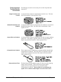
Crimp-and-Insert
Terminal Module
Accessories
Single-Conductor and
Contact
The following accessories are necessary for use with crimp-and-insert
Option A3E:
A crimp-and-insert contact is crimped onto one end of a wire. The other
end is not terminated. Order Agilent 91510A.
Shielded-Twisted-Pair and
Contacts
A crimp-and-insert contact is crimped onto each conductor at one end of a
shielded-twisted-pair cable. The other end is not terminated. Order
Agilent 91511A.
Jumper Wire and Contacts
A crimp-and-insert contact is crimped onto each end of a single-conductor
jumper wire. This jumper is typically used to tie two pins together in a
single crimp-and-insert connector. Order Agilent 91512A.
Crimp-and-Insert Contacts
These contacts may be crimped onto a conductor and then inserted into a
crimp-and-insert connector. The crimp tool kit is required to crimp the
contacts onto a conductor and remove the contact from the connector.
Order Agilent 91515A.
Crimp-and-Insert Tools
The hand crimp tool (part number Agilent 91518A) is used for crimping
contacts onto a conductor. The pin extractor tool (part number
Agilent 91519A) is required for removing contacts from the
crimp-and-insert connector. These products are not included with
Option A3E or with the terminal option accessories listed earlier.
28
Module Setup and Installation
Chapter 1
Extra Crimp-and-Insert
Connectors
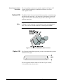
Option A3H
Note
The crimp-and-insert connector is normally supplied with Option A3E.
Contact Agilent Technologies if additional connectors are needed.
Order Agilent 91484B.
The Ribbon Cable Connector Terminal Option provides a terminal housing
and ribbon cable connectors. The connectors are designed to be used with
64-pin 0.05 inch center ribbon cables (not provided). Use Figure 1-12 to
make the connections.
In Figure 1-12, the center row of each connector is not used in the ribbon
cable. The center row of both connectors is module ground (GND).
Figure 1-11. Option A3H Ribbon Cable Connector
Option 135
The Terminal Module Housing Option provides a terminal housing with no
connectors of any type.
The user-supplied connector must be a DIN 41612 type C female,
11.6 mm dimension as shown above.
Chapter 1
Module Setup and Installation
29
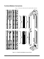
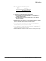
Terminal Module Connectors
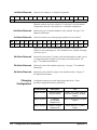
Figure 1-12 shows the connections at the terminal module connectors.
Figure 1-12. E1418A Terminal Module Connector Pinout
30
Module Setup and Installation
Chapter 1
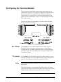
Configuring the Terminal Module
The screw-type terminal module contains jumpers that control how the
Agilent E1418A operates. The jumpers are shipped in a separate bag with
the terminal module. The Agilent E1418A will operate without any
jumpers installed. You can, however, store the jumpers on the terminal
module for later reconfiguration. Figure 1-13 shows the jumper locations
and example settings.
There are two jumpers for each channel; a P/J jumper and a V/I jumper.
The two jumpers work together.
Figure 1-13. P/J and V/I Jumpers
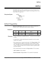
P/J Jumper
V/I Jumper
Notes
The P/J jumper sets the channel output mode to be either Program
Selectable or Jumper Selectable. When the jumper is in the program
selectable position, the channel output mode can be set via programming
commands. In the jumper selectable position, the channel output mode is
set via the V/I jumper.
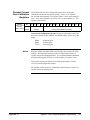
The V/I jumper sets the channel output mode to either voltage or current
when the P/J jumper is set to the Jumper Selectable position. When the P/J
jumper is set to Program Selectable, this jumper has no effect.
With no jumpers installed, the module will be in the Program Selectable
output mode.
When the P/J Jumper is set to the Jumper Selectable position, the output
mode cannot be changed with SCPI commands. The output mode following
a *RST common command will be the mode set by the V/I jumper.
Chapter 1
Module Setup and Installation
31
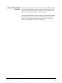
Options A3E and A3H
Terminals
The P/J jumper connection for each channel is named CH X PRGM JMPR
in the connection diagram on page 30. With no connection to this pin, the
module will operate in the Program Selectable mode. Shorting this pin to
GND will set the Jumper Selectable mode for channel X.
When CH X PRGM JMPR is shorted to GND, the CH X MODE JMPR pin
(corresponding to the V/I Jumper) sets the output mode for channel X. If
the pin is open, voltage output mode is selected. If the pin is shorted to
GND, current output mode is selected for channel X.
32
Module Setup and Installation
Chapter 1
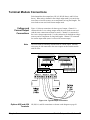
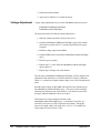
Terminal Module Connections
Each channel has four output lines; HI, LO, HS (Hi Sense), and LS (Low
Sense). When using a channel in the voltage output mode, you can use the
sense lines to increase accuracy or to compensate for long lead lengths. The
sense leads are not used in the current output mode.
Voltage and
Current Output
Connections
Note
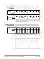
Figure 1-14 shows connections for three types of output. Channel 1 is
connected in the 2-wire voltage output mode, the sense leads are not used
(and the sense connections need not be made). Channel 2 is connected in
the 4-wire voltage output mode. Use this connection for the highest voltage
accuracy and to compensate for long lead lengths. Channel 3 is connected
for current output mode (sense is not used for current output).
The sense leads are internally disconnected for current output. External
wiring may be left connected to the sense outputs on the terminal module
with no effect.
Figure 1-14. Typical Output Connections
Options A3E and A3H
Terminals
Chapter 1
HI, HS, LO, and LS connections are shown on the diagram on page 30.
Module Setup and Installation
33
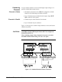
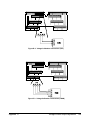
Combining
Channels
Channels in Series
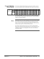
You can combine channels in series to obtain higher output voltages or in
parallel to obtain higher output currents.
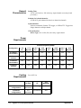
• All channels connected in series MUST be configured as isolated
channels (with isolated plug-on modules installed).
• Up to 3 channels may be combined, but the output voltage MUST
NOT exceed 42 Vdc/42 Vpeak.
Channels in Parallel
• Channels may be either Isolated or Non-Isolated.
• Up to 16 channels may be combined.
Figure 1-15 shows how to combine voltage channels (in series) and current
channels (in parallel).
CAUTIONS
All SERIES CONNECTED output channels MUST be configured as
ISOLATED OUTPUTS.
When combining output voltage channels, be sure not to exceed the
maximum module isolation rating of 42 Vdc or 42 Vpeak.
Figure 1-15. Combined Channels Output Connections
34
Module Setup and Installation
Chapter 1
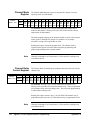
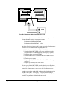
Connecting an
External Trigger
Source
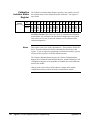
An external trigger input is provided on the terminal module. Use the
external trigger to externally synchronize multiple outputs or multiple
instruments. The External Trigger uses TTL levels. The trigger occurs
when the EXT TRIGn connection is pulled low for at least 1 µS. Typical
connections to the external trigger is shown in Figure 1-16.
Figure 1-16. External Trigger Connections
Options A3E and A3H
Terminals
Chapter 1
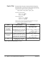
The external trigger line is located on the upper connector and is labeled
EXT TRIGn in the diagram on page 30.
Module Setup and Installation
35
Using the CAL
Output Terminals
The CAL Output Terminals provide one set of connections that can be used
to calibrate the output on all 16 channels. Calibration and adjustment
procedures are described in Appendix D beginning on page 155.
The CAL output terminals are available on the terminal module. There are
four lines; HI, LO, HS (Hi Sense), and LS (Low Sense). Typical CAL
output terminal connections are shown in Figure 1-17.
Figure 1-17. Calbus Connections
Options A3E and A3H
Terminals
36
The CAL Output Terminals are located on the upper connector and are labeled
CAL HI, CAL HS, CAL LO, and CAL LS in the diagram on page 30.
Module Setup and Installation
Chapter 1
Initial Operation
This section provides a programming example to help verify correct module
installation and operation. Additional programming examples and procedures
are given in the next chapter.
The examples shown here use BASIC and SCPI (Standard Commands for
Programmable Instruments). The example assumes a factory set logical
address of 72 for the Agilent E1418A module and uses an Agilent Command
Module for command interpretation. Examples in ANSI C are given in the
next chapter.
Note
Device Driver
This discussion applies to SCPI programming using the driver provided
with the module. The SCPI commands are described in Chapter 3 of this
manual. Appendix B of this manual describes direct register access.
The Agilent E1418A module is shipped a driver CD. This CD contains the
SCPI instrument driver, VXIplug&play drivers, example programs, and
Agilent VIC (VXI Installation Consultant). Follow the instructions contained
on the CD to properly install the device driver.
The following example shows how to query the command module and
verify that the correct device driver is installed:
10
20
30
40
50
DIM A$[256]
OUTPUT 70900;"DIAG:DRIV:LIST?"
ENTER 70900;A$
PRINT A$
END
In this example, the command module is located on GPIB (interface address 7)
and uses a primary address of 09. Responses to this example vary depending
upon the drivers loaded on your system. A typical response might look like:
E1418,E1418,A.01.00,RAM;SWITCH,SWITCHBOX,A.08.00,RAM;
SYSTEM,E1405A,A.08.00,ROM;IBASIC,IBASIC,A.04.02,ROM;
VOLTMTR,E1326A,A.05.00,ROM;SWITCH,SWITCHBOX,A.07.00,
ROM;COUNTER,E1332A,A.04.02,ROM;COUNTER,E1333A,A.04.02,
ROM;DIG_I/O,E1330A,A.04.03,ROM;D/A,E1328A,A.04.02,ROM
Verify that the string “ E1418,E1418,A.01.00,” is located somewhere
within the returned string.
Chapter 1
Module Setup and Installation
37
Module
Identification
This example can be used to verify that the logical address has been
correctly set, that the module is correctly installed, and that the module is
communicating with the command module. The terminal module does not
need to be installed for this example to work. This example queries the
module for the identification string.
10
20
30
40
50
DIM A$[256]
OUTPUT 70909;"*IDN?"
ENTER 70909;A$
PRINT A$
END
The response should be similar to one of the following:
HEWLETT-PACKARD,E1418A_8CH,xxxxAxxxx,A.01.00
or
HEWLETT-PACKARD,E1418A_16CH,xxxxAxxxx,A.01.00
The xxxxAxxxx portion of the response string is the module serial number.
38
Module Setup and Installation
Chapter 1
Chapter 2
Programming Examples
Using This Chapter
This chapter provides examples and descriptions of the most common
operations using the Agilent E1418A. Use this chapter to gain an overview of
how to program the module, and to obtain programming hints. The examples
shown in this chapter are in ANSI C and use SCPI commands to control the
module. The SCPI commands are described in detail in Chapter 3 of this
manual. SCPI usage conventions and syntax rules are described beginning on
page 60.
This chapter is divided into the following sections:
•
•
•
•
•
•
•
•
•
Program Examples
Note
Querying Module Identification and Configuration. . . . . . . . .
APPLy Output . . . . . . . . . . . . . . . . . . . . . . . . . . . . . . . . . . . .
Error Checking . . . . . . . . . . . . . . . . . . . . . . . . . . . . . . . . . . . .
SOURce Output . . . . . . . . . . . . . . . . . . . . . . . . . . . . . . . . . . .
Setting the Output Mode . . . . . . . . . . . . . . . . . . . . . . . . . . . .
Controlling the Output Relay. . . . . . . . . . . . . . . . . . . . . . . . .
Triggering. . . . . . . . . . . . . . . . . . . . . . . . . . . . . . . . . . . . . . . .
Using *OPC? . . . . . . . . . . . . . . . . . . . . . . . . . . . . . . . . . . . . .
Combining Output Channels . . . . . . . . . . . . . . . . . . . . . . . . .
Page 40
Page 45
Page 47
Page 50
Page 52
Page 53
Page 54
Page 56
Page 57
Example programs in ANSI C format are included on the driver CD
supplied with the Agilent E1418A. Most examples in this chapter are
included. The examples are ASCII files with the *.c extension.
The int data type is system dependent. These examples were developed on
a system where int is a 16-bit integer. Other systems may define int to be a
different width.
In the examples, the Agilent VISA Transition Library is used for I/O
operations with the VXIbus. An Agilent command module
(Agilent E1405/E1406) is used and controlled via GPIB.
To use the Agilent VISA Transition Library (abbreviated as VTL), include
the visa.h header file.
#include visa.h
Chapter 2
Programming Examples
39
Agilent VTL function calls and data types typically begin with the lower
case letters vi. Output and enter are performed with functions named
viPrintf and viScanf. Both these functions require a session (a VTL
defined I/O function) to uniquely identify the device being controlled. In
the examples, the session has been named dac.
Querying Module Identification and Configuration
This example will query the module for the identification string and
determine the module configuration.
The module identification is obtained using the IEEE-488 Command *IDN?.
!Send query to the module.
*IDN?
!Enter a string.
The string returned should be similar to one of the following:
HEWLETT-PACKARD,E1418A_8CH,xxxxAxxxxx,A.01.00
or
HEWLETT-PACKARD,E1418A_16CH,xxxxAxxxxx,A.01.00
The xxxxAxxxxx portion of the response string is the module serial
number.
The module configuration is obtained using the DIAGnostic:CONFiguration?
query.
!Send query to the module.
DIAG:CONF?
!Enter six integers and decode the integers.
40
Programming Examples
Chapter 2
The DIAG:CONF? query returns six integers. The six integers returned
contain the module configuration and have the following meaning.
Integer
Returned
Meaning
1st
Expansion Board ID in the form: 0 = present, 7 = none
(expansion board contains channels 9 through 16)
2nd
Terminal Module ID in the form
0 = screw type, 7 = none or other
3rd
Isolated/Non-isolated Channel status
A bit set to 0 indicates an isolated channel
A bit set to 1 indicates a non-isolated channel or no plug-on
module installed (DO NOT operate the module without a plug-on
module)
Bits 0 – 15 correspond to channels 1 – 16, respectively*
4th
Channel Mode
A bit set to 0 indicates a current output channel
A bit set to 1 indicates a voltage output channel
Bits 0 – 15 correspond to channels 1 – 16, respectively*
5th
Channel Output State
A bit set to 0 indicates the channel output relay is closed
A bit set to 1 indicates the channel output relay is open
Bits 0 – 15 correspond to channels 1 – 16, respectively*
6th
Channel Mode Programmable State (P/J Jumper)
A bit set to 0 indicates a channel is not mode programmable
A bit set to 1 indicates a channel is mode programmable
Bits 0 – 15 correspond to channels 1 – 16, respectively*
* For 8-channel configurations, the upper 8 bits of integers 3, 4, 5, and 6 are set to 1’s.
For example, if the following six integers are returned, the module has the
configuration indicated.
Chapter 2
Integer
Decimal
Value
1st
7
No expansion board installed
(Only channels 1 through 8).
2nd
7
No Terminal Module installed or
unknown terminal module installed.
3rd
-1
All channels are non-isolated.
4th
-1
All channels are voltage output channels.
5th
-1
All channel outputs are disabled
(all output relays are open).
6th
-1
All channels are output mode
programmable.
Configuration
Programming Examples
41
Configuration
Example
The following program segment demonstrates how to read the module
identification string and the configuration. The configuration integers are
bit manipulated using the C operator for bit shifting result = result <<1
(a one bit shift to the left).
•
•
•
/** FUNCTION PROTOTYPES **/
void main (void);
void err_handler(ViSession vi, ViStatus x);
/* VTL error routine
*/
void sys_err(ViSession resource);
/* Checks for SCPI programming errors */
/** GLOBAL **/
ViStatus err;
ViSession defaultRM, cmd, dac;
•
•
•
void main (void)
{
int i,num_chan,result = {0},config [6]={0};
char buf[256] = { 0 };
/*** Check the module identification
***/
err=viPrintf(dac, “*IDN?\n”);
/* request id from the module */
err=viScanf(dac, “%t”, &buf);
/* enter string returned
*/
printf (“Module is identified as a %s\n”, buf);
/* print the result
*/
/*** Get the module configuration
***/
err=viPrintf(dac, “DIAG:CONF?\n”); /* request module configuration */
err=viScanf(dac, “%,6d”, &config); /* returns six integers
*/
/* Decode the first integer */
result=config[0]; /* Expansion board */
if (result < 7)
{
printf (“Module is a 16 channel device\n”);
num_chan = 16;
}
else
{
printf (“Module is an 8 channel device\n”);
num_chan=8;
}
42
Programming Examples
Chapter 2
/* Decode the second integer */
result = config [1];
/* Terminal Module */
if (result > 0)
{
printf (“Module does NOT have a terminal module installed\n”);
}
else
{
printf (“Module has a screw-type terminal module installed\n”);
}
/* Decode the third integer */
result=config[2];
/* Isolated or non-isolated outputs */
if (num_chan < 9) result = result << 8; /* strip upper 8 bits */
for (i=num_chan;i>0;i – –)
{
if (result >= 0x8000)
{
printf (“Channel %d is configured for non-isolated output\n”,i);
}
else
{
printf(“Channel %d is configured for isolated output\n”,i);
}
result = result << 1;
}
/* Decode the fourth integer */
result=config[3];
/* Output Mode Voltage or Current */
if (num_chan < 9) result = result << 8; /* strip upper 8 bits */
for (i=num_chan;i>0;i – –)
{
if (result >= 0x8000)
{
printf (“Channel %d is set to voltage output mode\n”,i);
}
else
{
printf(“Channel %d is set to current output mode\n”,i);
}
result = result << 1;
}
Chapter 2
Programming Examples
43
/* Decode the fifth integer */
result=config[4];
/* Channel relay open or closed */
if (num_chan < 9) result = result << 8; /* strip upper 8 bits */
for (i=num_chan;i>0;i – –)
{
if (result >= 0x8000)
{
printf (“Channel %d output is disabled\n”,i);
}
else
{
printf(“Channel %d output is enabled\n”,i);
}
result = result << 1;
}
/* Decode the sixth integer */
result=config[5];
/* P/J Jumper position */
if (num_chan < 9) result = result << 8; /* strip upper 8 bits */
for (i=num_chan;i>0;i – –)
{
if (result >= 0x8000)
{
printf (“Channel %d output mode is programmable\n”,i);
}
else
{
printf(“Channel %d output mode is fixed and jumper selected\n”,i);
}
result = result << 1;
}
•
•
•
}
44
Programming Examples
Chapter 2
APPLy Output
The APPLyn subsystem commands provide the easiest method to output
voltages or currents.
/* Set channel 1 for 5.0 Volt output */
APPLy1:VOLTage 5.000
/* Channel is set to voltage output and 5.000 V applied */
/* Set channel 8 for 10 mA output */
APPLy8:CURRent 0.0100
/* Channel is set to current output and 10 mA applied */
The APPLyn subsystem outputs the voltage or current specified on the
channel specified immediately. The output relay for that channel is closed.
Other channel outputs and output states are not disturbed.
An APPLyn subsystem command performs several actions with a single
command. Each APPLyn command affects a single channel and:
– Sets the channel output mode (voltage or current).
– Sets the output value (volts or amps).
– Enables the outputs (closes the output relay).
The output channel remains enabled, and outputs the last programmed
voltage or current value, unless you take explicit action to turn off the
output. For example, if you send two APPLyn commands to the same
channel, the first command sets an output value and closes the output relay.
The second command changes only the output value (since the relay is
already closed).
/* Set channel 1 for 5.0 Volt output */
APPLy1:VOLTage 5.000
/* Channel 1 is set to voltage output and 5.000 V applied */
/* Now set channel 1 for 6.0 Volt output */
APPLy1:VOLTage 6.000
/* Channel 1 is set to voltage output and 6.000 V applied */
The commands above will set a 5.000 Volt output on Channel 1, and then
set a 6.000 Volt output on channel 1. The output relay is not affected by the
second command.
Chapter 2
Programming Examples
45
The output can also be disabled before changing the mode or output value.
Use the OUTPutn commands to disable the output.
/* Set channel 1 for 5.0 Volt output */
APPLy1:VOLTage 5.000
/* Disable the output */
OUTPut1 OFF
/* Channel 1 output relay is opened */
/* Now, enable the output */
OUTPut1 ON
/* Channel 1 is set to voltage output and 5.000 V applied */
/* Disable the output */
OUTPut1 OFF
/* Now set channel 1 for 20 mA current output */
APPLy1:CURRent .0200
/* Channel 1 is set to current output and 20 mA applied */
The OUTPut subsystem commands only affect the output relay. The
programmed mode and output value for a given channel is not changed.
Once the mode is set and the desired output value programmed, the output
can be turned on or off as needed with the OUTPutn[:STATe] command.
It is also possible, with the APPLyn commands, to change the channel
output mode from voltage to current.
/* Set channel 1 for 5.0 Volt output */
APPLy1:VOLTage 5.000
/* Channel 1 is set to voltage output and 5.000 V applied */
/* Now set channel 1 for 20 mA current output */
APPLy1:CURRent .0200
/* Channel 1 is set to current output and 20 mA applied */
During the change from voltage to current (or current to voltage), the
channel output relay is opened. Sending a command sequence similar to the
one above performs the following actions:
–
–
–
–
–
46
Programming Examples
Programs channel 1 to the voltage mode and 5.000 Volts output.
Closes the channel 1 output relay.
Opens the channel 1 output relay.
Programs channel 1 to current mode and 20 mA output.
Closes the channel 1 output relay.
Chapter 2
Error Checking
To develop programs you will need to create one or more error checking
routines. For example, you will need routines to check for errors in the
following operations:
– I/O operations to the VXIbus, and
– SCPI commands to the module.
I/O Error Checking
I/O error checking is specific to the type of I/O library you are using to
communicate with the VXIbus. In this manual and on the CD, the
Agilent VISA Transition Library is used.
Function calls to the Agilent VISA Transition Library (VTL) typically
begin with a lower case vi. For example, viPrintf is a VTL output function
call. The Agilent VTL I/O function calls return a variable that can be tested
for errors against the VTL variable VI_SUCCESS. In the examples, the
variable err is used to trap the VTL errors and is declared as a global
variable of the ViStatus type (defined in visa.h).
I/O error checking is illustrated in the following program example. The
VTL error checking function is named error_handler. Errors found are
reported to the standard output device.
SCPI Error
Checking
You must also check for errors reported by the SCPI driver. The SCPI
driver reports errors in response to the SYSTem:ERRor? query.
/* Repeat …
*/
SYST:ERR?
/* …until no errors found */
The query returns two values: an integer error code and an error description
string. The integer value returns +0 and the string returns “ No Error” if
no errors are found.
SCPI errors are reported in an error queue. The error queue is a first in, first
out queue. Each response to the SYSTem:ERRor? query removes one error
from the queue. Multiple SCPI errors may be generated by a single
incorrect command and the error queue should be read until it reports +0,
"No Error".
Chapter 2
Programming Examples
47
SCPI error checking is illustrated in the following program example. The
SCPI error routine is named sys_error. Errors found are reported to the
standard output device.
•
•
•
/** FUNCTION PROTOTYPES **/
void main (void);
void err_handler(ViSession vi, ViStatus x); /* VTL error routine
void sys_err(ViSession resource);
/* SCPI error routine
•
•
•
*/
*/
/** GLOBAL **/
ViStatus err;
ViSession defaultRM, cmd, dac;
•
•
•
void main (void)
{
/*** Open the resource manager, command module, and dac sessions ***/
viOpenDefaultRM (&defaultRM);
viOpen (defaultRM, CMD_ADDRESS, VI_NULL, VI_NULL, &cmd);
viOpen(defaultRM, DAC_ADDRESS, VI_NULL, VI_NULL, &dac);
/*** Set the timeout for the dac ***/
viSetAttribute(dac, VI_ATTR_TMO_VALUE, 10000); /* 10 second timeout */
err=viPrintf(dac, “*RST\n”);
/* reset the dac */
if(err < VI_SUCCESS) err_handler(dac, err); /* VTL error check */
sys_err (dac);
/* SCPI error check */
•
•
•
}
/***VTL Error handling function ***/
void err_handler (ViSession dac, ViStatus err)
{
char buf[1024]={0};
viStatusDesc(dac,err,buf);
printf(“VTL ERROR = %s\n”, buf);
return;
}
/***End of VTL error handler ***/
48
Programming Examples
Chapter 2
•
•
•
/*** SCPI Error check
***/
void sys_err(ViSession resource)
{
char buf [1024] = {0};
int err_no;
err = viPrintf (resource, “SYST:ERR?\n”);
/* query error queue
*/
if (err < VI_SUCCESS) err_handler(resource,err);
err = viScanf (resource,"%d%t",&err_no,&buf);
/* get error number and string */
if (err < VI_SUCCESS) err_handler(resource,err);
while (err_no != 0)
{
printf (“\nCommand Error: %d,%s\n”,err_no,buf);
err = viPrintf (resource, “SYST:ERR?\n”);
/* query error queue
*/
if (err < VI_SUCCESS) err_handler(resource,err);
err = viScanf (resource,"%d%t",&err_no,&buf);
/* get error number and string */
if (err < VI_SUCCESS) err_handler(resource,err);
}
return;
}
/*** End of SCPI error check ***/
Chapter 2
Programming Examples
49
SOURce Output
Setting an output on a channel is a three step process:
– Set the channel mode (voltage or current)
– Set the channel output value (volts or amps)
– Enable the output (close the channel output relay)
As described previously, a single APPLyn command performs all three of
these actions. In some cases you may need more control of each step in the
output process. The following commands perform the same action as a
single APPLyn command.
/* Set channel 1 voltage mode */
SOURce1:FUNCtion:MODE VOLTage
/* Channel 1 is set to voltage output */
/* Set channel 1 voltage output */
SOURce1:VOLTage 5.000
/* Channel 1 is set to output 5.000 Volts */
/* Turn on the output */
OUTPut1 ON
/* Channel 1 output is enabled */
The SOURcen subsystem contains two types of commands to set current or
voltage output. The type used in the above examples has the form:
SOURcen:CURRent[:LEVel][:IMMediate][:AMPLitude] <value>
SOURcen:VOLTage[:LEVel][:IMMediate][:AMPLitude] <value>
The implied commands (enclosed in brackets [ ]) are not shown in the
examples. The commands shown above immediately program the output
values. The SOURcen subsystem also contains commands of the form:
SOURcen:CURRent[:LEVel]:TRIGgered[:AMPLitude] <value>
SOURcen:VOLTage[:LEVel]:TRIGgered[:AMPLitude] <value>
These commands are used with the trigger system to control when the
outputs are applied. The trigger system is described on page 54.
50
Programming Examples
Chapter 2
Like the APPLyn commands, you can change the output value by sending
additional SOURcen commands. Changing the output value with the
SOURcen commands does not open the output relay.
/* Set channel 1 voltage mode */
SOURce1:FUNCtion:MODE VOLTage
/* Set channel 1 voltage output */
SOURce1:VOLTage 5.000
/* Turn on the output */
OUTPut1 ON
/* Channel 1 output is enabled */
/* Send a new output voltage */
SOURce1:VOLTage 15.000
Changing the output mode with the SOURcen commands opens the output
relay.
/* Set channel 1 voltage mode */
SOURce1:FUNCtion:MODE VOLTage
/* Set channel 1 voltage output */
SOURce1:VOLTage 5.000
/* Turn on the output */
OUTPut1 ON
/* Channel 1 output is enabled and 5 volts applied */
/* Send a new output mode */
SOURce1:FUNCtion:MODE CURRent
/* Channel 1 output is disabled */
/* Set channel 1 output current */
SOURce1:CURRent .01
/* Channel 1 is programmed for 10 mA */
/* Turn on the output */
OUTPut1 ON
/* Channel 1 output is enabled and 10 mA applied */
Chapter 2
Programming Examples
51
Setting the Output Mode
The output mode can be set using commands in the SOURce subsystem.
SOURcen:FUNCtion:MODE VOLTage
SOURcen:FUNCtion:MODE CURRent
The mode can also be set on the terminal module with the P/J jumpers and
V/I jumpers (see page 31). If the mode is set to Jumper selectable with the
P/J jumper on the terminal module, the mode cannot be changed with the
SCPI commands and the output mode is set by the V/I jumper (also on the
terminal module, see page 31).
For example, if on the terminal module, channel 1 P/J jumper is set to
Jumper Selectable and the V/I jumper is set to current mode, the following
command will each generate an error:
SOURce1:FUNCtion:MODE VOLT
The error returned is:
+3012 Channel cannot be programmed to this mode, check jumpers
Appendix C, starting on page 151 contains a full list of the errors that may
be generated by the SCPI commands for the Agilent E1418A.
52
Programming Examples
Chapter 2
Controlling the Output Relay
There are three programming methods to enable the output of a channel
(close the output relay).
• The APPLyn:VOLTage <value> or APPLyn:CURRent <value>
command both program an output value and close the output relay
on a single channel.
• The OUTPutn:STATe ON command closes the output relay for a
single channel. The last programmed mode and output value remains
in effect.
• The DIAGnostic:OUTPut:ALL:STATe ON command closes all output
relays. The order of relay closure is not guaranteed.
There are three programming methods to disable the output of a channel
(open the output relay).
• Send the OUTPutn:STATe OFF command to open a single channel
output relay without changing the programmed mode or output value
for that channel or affecting any other channels.
• Send *RST to program all channels to voltage mode, 0 volts output,
and open all output relays. *RST will not change the output mode if
the P/J jumper is set to Jumper Selectable.
• Send the DIAGnostic:OUTPut:ALL OFF command to open all output
relays without changing the programmed mode or output value.
The output relay will also be opened and then closed by a change of output
mode using the APPLy commands.
• An APPLyn:VOLTage <value> followed by an
APPLyn:CURRent <value> command (or vice versa) will open and
then close the output relay.
All output relays will be opened, and left open, by the following commands.
• The SOURcen:FUNCtion:MODE VOLTage or
SOURcen:FUNCtion:MODE CURRent commands set output mode
for a single channel and opens the output relay for that channel.
Other channels are not affected.
• The *RST command performs a reset and leaves the output relays
open on all channels (the command also programs all channels to
voltage mode, 0 volts output unless the P/J jumper is set to Jumper
Selectable).
• The *TST? command performs a self-test and leaves the output
relays open on all channels. Programmed output modes are restored
following the self-test.
Chapter 2
Programming Examples
53
Triggering
To synchronize outputs to external events, backplane events, or software
events use the TRIGger subsystem commands. Triggering an output from
the module involves four steps:
1.
2.
3.
4.
Set the trigger source.
Set one or more channels for triggered output.
Put the trigger system in the wait-for-trigger state.
Send the trigger event.
The TRIGger:SOURce <source> command sets the trigger source. One of
four trigger sources can be specified.
• VXIbus backplane trigger — one of the eight TTL trigger lines
defined in the VXIbus P2 connector. The lines are named
*TTLTRG0 through *TTLTRG7. Any one of these trigger lines
may be used as a trigger source.
• Software trigger — generated within the controlling program.
• Immediate trigger — places the trigger system in the wait-for-trigger
state and then immediately triggers the output.
• External Trigger — an input on the terminal module (see page 35).
Use this source to synchronize the outputs to an external event.
The SOURcen:VOLTage[:LEVel]:TRIGgered[:AMPLitude] and
SOURcen:CURRent[:LEVel]:TRIGgered[:AMPLitude] commands program a
channel output value when the trigger conditions are met.
The INITiate:IMMediate command places the trigger system in the
wait-for-trigger state. The trigger event depends upon the trigger source set.
The trigger system is common to all channels in the module. That is, a
single trigger event triggers the output on all channels that are waiting for
the trigger. The SOURce subsystem contains commands to put each
channel in the wait-for-trigger state.
/* Set the trigger source for software trigger
*/
TRIGger:SOURce HOLD
/* Set channels 1 and 2 for triggered output
*/
SOURce1:VOLTage:TRIGgered 1.5000
SOURce2:VOLTage:TRIGgered -2.5000
/* Close the output relays
*/
OUTPut1 ON
OUTPut2 ON
/* Put the trigger system in the wait-for-trigger state */
54
Programming Examples
Chapter 2
INITiate
/* Send the trigger event
*/
TRIGger:IMMediate
/* Channels 1 and 2 output the programmed voltages */
Note that the channels must be set for triggered output (using the SOURce
subsystem) before the trigger system is changed to the wait-for-trigger state
(using the INITiate command). If you send the SOURcen commands after
the INITiate command, the following error is reported:
+3014 Illegal while initiated
Once the outputs have been triggered (using TRIGger:IMMediate in the
previous example) the trigger system is set back to the trigger idle state. New
triggered channel output values can be programmed and the trigger system put
in the wait-for-trigger state. The triggering process is illustrated below.
Note
Once an output is enabled and a voltage or current output, that value
remains on the output. Sending subsequent SOURn:VOLT:TRIG or
SOURn:CURR:TRIG commands will not change the output value until the
trigger event is received. The output may be disabled (output relay opened)
with the OUTPn OFF command.
The trigger source set using the TRIGger:SOURce command remains in
effect until it is changed or a reset occurs. Following a reset (*RST) the
trigger source is set to HOLD.
Chapter 2
Programming Examples
55
Using *OPC?
As shown, the examples have made no attempt to coordinate the program
execution with the Agilent E1418A module. In some cases, you may need to
pause program execution until the module has completed executing the
commands.
The IEEE-488 common command *OPC? can be used to keep the program
and the module synchronized. The *OPC? query returns a 1 when all
programmed operations are complete. The program can wait for the
response before executing additional statements. The returned value is
unimportant (always a 1).
/* Set channel 1 voltage mode */
SOURce1:FUNCtion:MODE VOLTage
/* Set channel 1 voltage output */
SOURce1:VOLTage 5.000
/* Turn on the output */
OUTPut1 ON
*OPC?
/* enter the response
*/
*OPC? is used to synchronize the program with the module since program
execution waits for the response. The command may be combined using the ;
as described under “Linking Commands” on page 62. For example,
/* Set channel 1 voltage mode */
SOURce1:FUNCtion:MODE VOLTage;*OPC?
/* enter the response
56
Programming Examples
*/
Chapter 2
Combining Output Channels
As described on page 34, multiple outputs may be combined to obtain higher
voltage or current outputs. A triggered output is recommended for combined
channels. The general sequence used to control combined channels is:
1.
2.
3.
4.
Set the trigger source.
Close the output relays.
Set the desired output on all combined channels.
Trigger the output.
For example, when three current channels are combined in parallel as
shown on page 34, the following commands can be used.
/* Set the trigger source for external trigger
*/
TRIGger:SOURce EXT
/* Close the output relays
*/
OUTPut9 ON
OUTPut10 ON
OUTPut11 ON
/* Set channels 9, 10, and 11 for triggered output
*/
SOURce9:CURRent:TRIGgered MAX
SOURce10:CURRent:TRIGgered MAX
SOURce11:CURRent:TRIGgered .0100
/* Put the trigger system in the wait-for-trigger state */
INITiate
/* Wait for the trigger event
*/
/* When the trigger occurs…
*/
/* …output 50 mA
*/
When combining channels in parallel, for increased current output, channels
may be configured with either isolated or non-isolated plug-on modules.
When combining channels in series, for increased voltage output, all
combined channels MUST be configured with isolated plug-on modules.
CAUTION
Chapter 2
When combining output voltage channels (series connections) you must
ensure that the output does not exceed the maximum isolation rating of ±42
Vdc/42 Vpeak. Up to three channels may be combined, but the controlling
program must ensure that all three channels together are NEVER set
beyond ±42 Vdc.
Programming Examples
57
Notes
58
Programming Examples
Chapter 2
Chapter 3
Agilent E1418A SCPI Command Reference
Using This Chapter
This chapter describes Standard Commands for Programmable Instrumentation
(SCPI) and summarizes IEEE 488.2 Common (*) Commands applicable to the
Agilent E1418A D/A Converter Module. This chapter contains the following
sections:
•
•
•
•
•
•
•
•
•
•
•
•
•
•
•
Command Types . . . . . . . . . . . . . . . . . .
SCPI Command Reference . . . . . . . . . . . . .
ABORt Subsystem . . . . . . . . . . . . . . . . .
APPLy Subsystem . . . . . . . . . . . . . . . . .
CALibration Subsystem . . . . . . . . . . . . . . .
DIAGnostic Subsystem . . . . . . . . . . . . . . .
INITiate Subsystem . . . . . . . . . . . . . . . . .
OUTPut Subsystem . . . . . . . . . . . . . . . . .
SOURce Subsystem . . . . . . . . . . . . . . . . .
STATus Subsystem . . . . . . . . . . . . . . . . .
SYSTem Subsystem . . . . . . . . . . . . . . . .
TEST Subsystem . . . . . . . . . . . . . . . . . .
TRIGger Subsystem . . . . . . . . . . . . . . . . .
IEEE 488.2 Common Command Quick Reference .
Agilent E1418A Command Quick Reference . . .
.
.
.
.
.
.
.
.
.
.
.
.
.
.
.
.
.
.
.
.
.
.
.
.
.
.
.
.
.
.
.
.
.
.
.
.
.
.
.
.
.
.
.
.
.
.
.
.
.
.
.
.
.
.
.
.
.
.
.
.
.
.
.
.
.
.
.
.
.
.
.
.
.
.
.
.
.
.
.
.
.
.
.
.
.
.
.
.
.
.
. Page 59
. Page 62
. Page 63
. Page 64
. Page 66
. Page 76
. Page 80
. Page 81
. Page 84
. Page 95
. Page 100
. Page 101
. Page 104
. Page 106
. Page 107
Command Types
Commands are separated into two types: IEEE 488.2 Common Commands and
SCPI Commands.
Common
Command
Format
The IEEE 488.2 standard defines the common commands that perform functions
like reset, self-test, status byte query, etc. Common commands are four or five
characters in length, always begin with the asterisk character (*), and may include
one or more parameters. The command keyword is separated from the first
parameter by a space character. Common commands are not documented, except in
a general manner, in this manual. Some examples of common commands are:
*RST
*ESR 32
*STB?
Chapter 3
Agilent E1418A SCPI Command Reference
59
SCPI Command Format
SCPI commands perform functions like setting outputs, querying instrument states,
or retrieving data. The command structure is a hierarchical structure that usually
consists of a top level (or root) command, one or more lower level commands, and
their parameters. The following example shows part of a typical subsystem:
SOURcen:
FUNCtion:
MODE <CURRent | VOLTage>
SOURcen: is the root command (where n is replaced by the channel number in the
range of 1 to 16), FUNCtion: is a second level command, MODE is a third level
command, and <CURRent | VOLTage> is an input parameter.
Command A colon (:) always separates one command from the next lower level command.
Separator This is illustrated as follows:
SOURcen:FUNCtion:MODE VOLT
Colons separate the root command from the second level (SOURcen:FUNCtion) and
the second from third level (FUNCtion:MODE), and so forth.
Abbreviated and The command syntax shows most commands as a mix of upper and lower case
Short Commands letters. The upper case letters indicate an abbreviated spelling for the command.
For shorter program lines, send only the abbreviated form. For better program
readability use the entire command. The instrument will accept either the
abbreviated form or the entire command.
For example, if the command reference syntax shows the command TRIGger, then
TRIG and TRIGGER are both acceptable forms. Other forms of TRIGger, such as
TRIGG or TRIGGE will generate an error.
The instrument does not distinguish between upper case and lower case characters.
Therefore TRIGGER, trigger, and TrigGeR are all acceptable.
Command keywords can be entered in their full form, as shown above, or can be
entered in their short form. In this manual, the entry required in short form
commands is always capitalized. The short form is generally used for examples in
this manual.
60
Agilent E1418A SCPI Command Reference
Chapter 3
Implied Implied commands appear in square brackets ([ ]) in the command syntax. (Note
Commands that the brackets are not part of the command and are not sent to the instrument.)
Suppose you send a second level command but do not send the preceding implied
command. In this case, the instrument assumes you intend to use the implied
command and it responds as if you had sent it. Examine this excerpt from the
STATus subsystem shown below:
STATus:
OPERation
[:EVENt]?
The third level command, EVENt, is implied. To read the value of the Event
Register, you can use either:
STATus:OPERation?
or
STATus:OPERation:EVENt?
Parameters Parameters are enclosed in greater than/less than symbols (< >) in the command
syntax. When more than one parameter is allowed, the parameters are separated by
a vertical line ( | ).
Parameter Types. The following table contains explanations and examples of
parameter types you might see later in this chapter. Parameters must always be
separated from the keywords by a space.
Parameter Type
Numeric
Explanations and Examples
Accepts all commonly used decimal representations of
numbers including optional signs, decimal points, and
scientific notation.
123, 123E2, -123, -1.23E2, .123, 1.23E-2, 1.23000E-01.
Special cases include MIN, MAX, and DEF.
Boolean
Represents a single binary condition that is either
true or false.
ON, OFF, 1, 0.
Discrete
Selects from a finite number of values. These parameters
use mnemonics to represent each valid setting.
An example is the SOURcen:FUNCtion:MODE <mode>
command where the <mode> parameter can be either
CURRent or VOLTage.
Optional Parameters. Parameters shown within square brackets ([ ]) are optional
parameters. (Note that the brackets are not part of the command and are not sent to
the instrument.) If you do not specify a value for an optional parameter, the
instrument chooses a default value.
Chapter 3
Agilent E1418A SCPI Command Reference
61
Linking
Commands
Linking IEEE 488.2 Common Commands with SCPI Commands. Use a
semicolon between the commands. For example:
*RST;APPLy2:VOLT 10 or INIT:IMM;*IDN?
Linking Multiple SCPI Commands. Use both a semicolon and a colon between
the commands. For example:
SOURce2:FUNCtion:MODE VOLT;:SOURce2:VOLTage 10
SCPI Command Reference
The following sections describe the Standard Commands for Programmable
Instruments (SCPI) commands for the Agilent E1418A D/A Converter Module.
Commands are listed alphabetically by subsystem and within each subsystem. A
command guide is printed in the top margin of each page. The guide indicates the
current subsystem on that page.
62
Agilent E1418A SCPI Command Reference
Chapter 3
ABORt
ABORt
The ABORt subsystem disables the trigger system and places the trigger system in
the trigger idle state.
Subsystem Syntax
ABORt
Parameters None.
Comments • Following this command, the trigger system is in the idle state. Sending an
INITiate command after ABORt returns the trigger system to the wait-for-trigger
state.
• Triggering is described in more detail on page 54.
• Related Commands: INITiate[:IMMediate]
Chapter 3
Agilent E1418A SCPI Command Reference
63
APPLy
APPLy
The APPLy subsystem enables and outputs a current or voltage on the specified channel.
Subsystem Syntax
APPLyn
:CURRent <value | MIN | MAX | DEF>
:VOLTage <value | MIN | MAX | DEF>
APPLyn:CURRent
APPLyn:CURRent <value | MIN | MAX | DEF> outputs a current on the specified
channel, n.
Parameters
Parameter
Name
Parameter
Type
Range of
Values
Default
APPLyn
keyword
1 to 8 or 1 to 16
1
<value>
numeric (float 32) or
discrete
-0.02 Amps to +0.02 Amps or
MIN | MAX | DEF
0
Comments • In the keyword, APPLyn, the valid range of n is:
1 to 8 for
E1418A, E1418A Option 002
1 to 16 for E1418A Option 001, E1418A Option 003.
Values of n outside these ranges will generate an error.
• The <value> parameter can range from -0.02 to +0.02 Amps.
MIN sets -0.02 Amps output.
MAX sets +0.02 Amps output.
DEF sets 0 Amps output.
• This command is affected by the state of the P/J jumper for this channel on the
terminal module. To use the APPLyn:CURRent command:
– the P/J jumper must be set to program selectable or, if set to jumper selectable,
– the V/I jumper must be set to the current mode.
These jumpers are described on page 31.
• Equivalent Commands: SOURcen:FUNCtion:MODE CURR,
SOURcen:CURRent[:LEVel][:IMMediate][:AMPLitude], OUTPutn[:STATe] ON
• *RST Condition:
– If the P/J jumper is set to program selectable:
output mode is set to voltage, 0 volts output, output relay open.
– If the P/J jumper is set to jumper selectable:
output mode is set by the V/I jumper, 0 volts or amps, output relay open.
64
Agilent E1418A SCPI Command Reference
Chapter 3
APPLy
APPLyn:VOLTage
APPLyn:VOLTage <value | MIN | MAX | DEF> outputs a voltage on the specified
channel, n.
Parameters
Parameter
Name
Parameter
Type
Range of
Values
Default
APPLyn
keyword
1 to 8 or 1 to 16
1
<value>
numeric (float 32) or
discrete
-16 V to +16 V or MIN | MAX | DEF
0
Comments • In the keyword, APPLyn, the valid range of n is:
1 to 8 for
E1418A, E1418A Option 002
1 to 16 for E1418A Option 001, E1418A Option 003.
Values of n outside these ranges will generate an error.
• The <value> parameter can range from -16 Volts to +16 Volts.
MIN sets -16 Volts output.
MAX sets +16 Volts output.
DEF sets 0 Volts output.
• This command is affected by the state of the program jumper on the terminal
module for this channel. To use the APPLyn:VOLT command:
– the P/J jumper must be set to program selectable or, if set to jumper selectable,
– the V/I jumper must be set to the voltage mode.
This jumper is described on page 31.
• Equivalent Commands: SOURcen:FUNCtion:MODE VOLT,
SOURcen:VOLTage[:LEVel][:IMMediate][:AMPLitude], OUTPutn[:STATe] ON
• *RST Condition:
– If the P/J jumper is set to program selectable:
output mode is set to voltage, 0 volts output, output relay open.
– If the P/J jumper is set to jumper selectable:
output mode is set by the V/I jumper, 0 volts or amps, output relay open.
Chapter 3
Agilent E1418A SCPI Command Reference
65
CALibration
CALibration
The CALibration commands are used during periodic calibration of the module.
Calibration is described in Appendix D of this manual, beginning on page 155. You
should review Appendix D before using any of these commands.
Subsystem Syntax
66
CALibration
:CONDition?
:CONFigure
:RESistance?
:RESet
:STORe
:TEST?
:VALue
:RESistance <value>
CALibrationn
:CONFigure
:CURRent?
:VOLTage?
:VALue
:CURRent? <value>
:VOLTage? <value>
Agilent E1418A SCPI Command Reference
Chapter 3
CALibration
CALibration:CONDition?
CALibration:CONDition? queries the module type and calibration status. The
query returns four 16-bit unsigned integers.
Parameters Returns: four unsigned 16-bit integers (uint16).
Comments • The integers returned indicate the module configuration and status at the last
calibration, not the current configuration of the module. The first and second
integers returned from this query can be compared to the first and third integers
returned from the DIAGnostic:CONFigure? query to determine if the module
configuration has changed since the last calibration.
Integer
Returned
Chapter 3
Meaning
1
Expansion Board ID in the form:
0 = present, 7 = none
(expansion board contains channels 9–16)
2
2nd 16-bit value indicates how the channels are configured (isolated
or non-isolated). A bit set to 0 indicates an isolated channel, a bit set
to 1 indicates a non-isolated channel. Bits 0–15 correspond to
channels 1–16, respectively.
3
3rd 16-bit value indicates the current calibration status for each
channel. A bit set to 0 indicates the channel is not calibrated for
current, a bit set to 1 indicates the channel has been calibrated for
current. Bits 0–15 correspond to channels 1–16, respectively.
4
4th 16-bit value indicates the voltage calibration status for each
channel. A bit set to 0 indicates the channel is not calibrated for
voltage, a bit set to 1 indicates the channel has been calibrated for
voltage. Bits 0–15 correspond to channels 1–16, respectively.
Agilent E1418A SCPI Command Reference
67
CALibration
CALibration:CONFigure:RESistance?
CALibration:CONFigure:RESistance? configures the module to perform
calibration of the internal calibration resistor and returns a 0 or 1 indicating the
readiness of the module.
Parameters Returns: signed 16-bit integer (int16). 1 = ready, 0 = not ready.
Comments • The internal calibration resistor should be calibrated before calibrating the
channels in current mode.
• This query configures the module for a 4-wire resistance measurement at the CAL
output terminals when the calibration point is set to CALB (following a *RST or
DIAGnostic:CALibration:OUTPut[:MODE] CALBus command).
• This query may also be used to set an external calibration resistor value when
calibrating at each channel output.
• This query is used together with the CALibration:VALue:RESistance command to
calibrate the current calibration resistor.
• Refer to Appendix D, “Voltage/Current Output Adjustment”, starting on page 155,
for additional information about this command.
• Related Commands: CALibration:VALue:RESistance
CALibration:RESet
CALibration:RESet reloads, for module use, the calibration constants stored in
non-volatile memory.
Parameters • None.
Comments • This command, with respect to the calibration constants, performs the same action
as power-on.
• At power-on, or following this command, calibration constants stored in
non-volatile memory are loaded into the module where they are used during
output operations.
• If the trigger system is waiting for a trigger when this command is received,
an error is generated.
• This command opens all output relays.
• Related Commands: CALibration:STORe
68
Agilent E1418A SCPI Command Reference
Chapter 3
CALibration
CALibration:STORe
CALibration:STORe loads the stored non-volatile memory calibration constants
with the calibration constants currently in use by the module.
Parameters None.
Comments • This command sets the calibration constants in non-volatile memory if the CAL
Store Enable Jumper is properly set (see page 157). Non-volatile memory has
finite life, based upon the number of writes. Use this command sparingly.
• At power-on, calibration constants stored in non-volatile memory are loaded into
the module where they are used during output operations.
• When this command is received, the checksum is verified using the constants
currently in use by the module. If the checksum does not verify, the non-volatile
memory is not updated and an error is generated.
• Refer to Appendix D, “Voltage/Current Output Adjustment”, starting on page 155,
for additional information about this command.
• Related Commands: CALibration:RESet
CALibration:TEST?
CALibration:TEST? performs an internal rough check of the calibration of each
channel and returns an integer indicating the channel calibration condition.
Calibration is checked to approximately ± 2%.
Parameters Returns: unsigned 16-bit integer (uint16).
Comments • Following the completion of this query all outputs are disabled and set to 0 Volts
or 0 Amps based on the channel mode.
• This query returns a 16-bit integer indicating the calibration status of each channel.
– Bits set to 0 indicate no calibration errors were found.
– Bits set to 1 indicate a channel with questionable calibration.
– Bits 0–15 correspond to channels 1–16, respectively.
• If the trigger system is waiting for a trigger when this command is received, an
error is generated.
Chapter 3
Agilent E1418A SCPI Command Reference
69
CALibration
CALibration:VALue:RESistance
CALibration:VALue:RESistance <value> enters a new measured value to be used
as the internal calibration resistor constant by the module.
Parameters
Parameter
Name
Parameter
Type
Range of
Values
Default
<value>
numeric (float 32)
Must be > 0 ohms
none
Comments • The new calibration constant is used by the module but not stored in non-volatile
memory.
• This command is used together with the CALibration:CONFigure:RESistance?
query to calibrate the internal current calibration resistor.
• The internal calibration resistor should be calibrated before calibrating channels in
current mode. When calibrating at the CAL connections and using the internal
calibration resistor, the value need only be entered once to calibrate all channels.
• If using an external resistor to calibrate current mode, you must calibrate at each
channel output. External resistances in the range of 50 Ω to 500 Ω are recommended.
• Refer to Appendix D, “Voltage/Current Output Adjustment”, starting on page 155,
for additional information about this command.
• Related Commands: CALibration:STORe, CALibration:CONFigure:RESistance?
70
Agilent E1418A SCPI Command Reference
Chapter 3
CALibration
CALibrationn:CONFigure:CURRent?
CALibrationn:CONFigure:CURRent? configures the channel for current mode
calibration and returns a 0 or 1 to indicate the channel’s readiness for calibration.
Parameters
Parameter
Name
Parameter
Type
Range of
Values
Default
CALibrationn
keyword
1 to 8 or 1 to 16
1
Returns: an unsigned 16-bit integer (uint16). 1 = ready, 0 = not ready.
Comments • In the keyword, CALibrationn, the valid range of n is:
1 to 8 for
E1418A, E1418A Option 002
1 to 16 for E1418A Option 001, E1418A Option 003.
Values of n outside these ranges will generate an error.
• This command is used together with the CALibrationn:VALue:CURRent? <value>
query to perform current mode calibration.
• The calibration is performed either at the CAL output terminals or at an individual
channel. The choice is made using the DIAGnostic:CALibration:OUTPut[:MODE]
command.
– When the DIAG:CAL:OUTP:MODE CALBus command (also the reset state)
is used, the output relay routes the calibration current to the CAL output
terminals (and opens all channel output terminals).
– When the DIAG:CAL:OUTP:MODE CHANnel command is used, the output relay
routes the calibration current to the channel terminals (the CAL terminals are
not connected).
The DIAG:CAL:OUTP:MODE command must be sent to the module before the
CALibrationn:CONFigure:CURRent? query.
• This query will generate an error if the trigger system is waiting for a trigger event
when this command is received.
• This query returns a 0 to indicate that the channel is not ready for calibration, and
a 1 to indicate the channel is ready for calibration.
• This query is affected by the state of the program jumper for this channel on the
terminal module. To use this command:
– the P/J jumper must be set to program selectable or, if set to jumper selectable,
– the V/I jumper must be set to the current mode. The jumpers are described on
page 31.
• Refer to Appendix D, “Voltage/Current Output Adjustment”, starting on page 155,
for additional information about this command.
• Related Commands: CALibrationn:VALue:CURRent?,
DIAGnostic:CALibration:OUTPut[:MODE]
Chapter 3
Agilent E1418A SCPI Command Reference
71
CALibration
CALibrationn:CONFigure:VOLTage?
CALibrationn:CONFigure:VOLTage? configures the channel for voltage mode
calibration and returns a 0 or 1 to indicate the channel’s readiness for calibration.
Parameters
Parameter
Name
Parameter
Type
Range of
Values
Default
CALibrationn
keyword
1 to 8 or 1 to 16
1
Returns: an unsigned 16-bit integer (uint16). 1 = ready, 0 = not ready.
Comments • In the keyword, CALibrationn, the valid range of n is:
1 to 8 for
E1418A, E1418A Option 002
1 to 16 for E1418A Option 001, E1418A Option 003.
Values of n outside these ranges will generate an error.
• This command is used together with the CALibrationn:VALue:VOLTage? query to
perform voltage mode calibration.
• The calibration is performed either at the CAL output terminals or at an individual
channel. The choice is made using the DIAGnostic:CALibration:OUTPut[:MODE]
command.
– When the DIAG:CAL:OUTP:MODE CALBus command (also the reset state)
is used, the output relay routes the calibration voltage to the CAL output
terminals (and opens all channel output terminals).
– When the command DIAG:CAL:OUTP:MODE CHANnel is used, the output
relay routes the calibration voltage to the channel terminals (the CAL terminals
are not connected).
The DIAGnostic:CALibration:OUTPut[:MODE] command must be sent to the
module before the CALibrationn:CONFigure:VOLTage? query.
• This query will generate an error if the trigger system is waiting for a trigger event
when this command is received.
• This query returns a 0 to indicate that the channel is not ready for calibration,
and a 1 to indicate the channel is ready for calibration.
• This command is affected by the state of the program jumper for this channel on
the terminal module. To use this command:
– the P/J jumper must be set to program selectable or, if set to jumper selectable,
– the V/I jumper must be set to the voltage mode.
The jumpers are described on page 31.
• Refer to Appendix D, “Voltage/Current Output Adjustment”, starting on page 155,
for additional information about this command.
• Related Commands: CALibrationn:VALue:VOLTage?,
DIAGnostic:CALibration:OUTPut[:MODE]
72
Agilent E1418A SCPI Command Reference
Chapter 3
CALibration
CALibrationn:VALue:CURRent?
CALibrationn:VALue:CURRent? <value> enters a measured calibration value
and returns a value indicating the present state of the current calibration process.
Parameters
Parameter
Name
Parameter
Type
Range of
Values
Default
CALibrationn
keyword
1 to 8 or 1 to 16
1
<value>
numeric (float 32)
0.0 to 6.0 V
none
Returns: unsigned 16-bit integer (uint16).
Comments • In the keyword, CALibrationn, the valid range of n is:
1 to 8 for
E1418A, E1418A Option 002
1 to 16 for E1418A Option 001, E1418A Option 003.
Values of n outside these ranges will generate an error.
• This command is used together with the CALibrationn:CONFigure:CURRent?
query to perform voltage mode calibration. Following the CALn:CONF:CURR?
query, this command is used repetitively until the return value indicates that the
calibration is complete.
• The <value> parameter is the measured output voltage. A minimum of
9 measurements must be taken to calibrate a channel for current mode output
(a maximum of 50 measurements may be required).
• This query returns one of the following values:
Return
Value
Chapter 3
Meaning
0
Calibration is complete.
New constants are in RAM.
Resistance is calibrated.
1
More measurements are needed.
Resistance is calibrated.
2
Calibration is complete.
New constants are in RAM.
Resistance is not calibrated.
3
More Measurements are needed.
Resistance is not calibrated.
5
Calibration aborted.
Agilent E1418A SCPI Command Reference
73
CALibration
• A returned value of 5 (calibration aborted) is given if either:
a. The command is received when the module is in voltage calibration or
resistance calibration mode, or
b. The calibration in process has entered more than 50 values without a
successful calibration.
• If the internal calibration resistor is not calibrated, the channel is not marked as
calibrated following the completion of calibration (see the CALibration:CONDition?
query). The new calibration constants are used, however.
• When the channel current calibration is completed, the new calibration constants
are used by the module, but not stored in non-volatile memory.
• If a calibration is interrupted before completion (that is, by another command
being received), no constants will be changed.
• Refer to Appendix D, “Voltage/Current Output Adjustment”, starting on page 155,
for additional information about this command.
• Related Commands: CALibration:STORe, CALibrationn:CONFigure:CURRent?
CALibrationn:VALue:VOLTage?
CALibrationn:VALue:VOLTage? <value> enters a measured calibration value and
returns a value indicating the present state of the voltage calibration process.
Parameters
Parameter
Name
Parameter
Type
Range of
Values
Default
CALibrationn
keyword
1 to 8 or 1 to 16
1
<value>
numeric (float 32)
0 to 19.2 V
none
Returns: unsigned 16-bit integer (uint16).
Comments • In the keyword, CALibrationn, the valid range of n is:
1 to 8 for
E1418A, E1418A Option 002
1 to 16 for E1418A Option 001, E1418A Option 003.
Values of n outside these ranges will generate an error.
• This command is used together with the CALibrationn:CONFigure:VOLTage? query
to perform voltage mode calibration. Following the CALn:CONF:VOLT? query, this
command is used repetitively until the return value indicates that the calibration is
complete.
• The <value> parameter is the measured output voltage. A minimum of
9 measurements must be taken to calibrate a voltage output channel
(a maximum of 50 measurements may be required).
74
Agilent E1418A SCPI Command Reference
Chapter 3
CALibration
• This query returns one of the following values:
Return
Value
Meaning
0
Calibration is complete.
New constants are in RAM.
1
More measurements are needed.
5
Calibration aborted.
• A return value of 5 (calibration aborted) is given if either:
a. The command is received when the module is in current calibration or
resistance calibration mode, or
b. The calibration in process has entered more than 50 values without a
successful calibration.
• When the channel voltage calibration is completed, the new calibration constants
are used by the module, but not stored in non-volatile memory.
• If a voltage calibration is interrupted before completion (that is, by another
command being received), no constants are changed.
• Refer to Appendix D, “Voltage/Current Output Adjustment”, starting on page 155,
for additional information about this command.
• Related Commands: CALibration:STORe, CALibrationn:CONFigure:VOLTage?
Chapter 3
Agilent E1418A SCPI Command Reference
75
DIAGnostic
DIAGnostic
The DIAGnostic subsystem contains commands used to check the module
configuration, enable or disable all outputs simultaneously, change a channel’s
mode without opening and closing the output relay, and check the state of the trigger
on all channels.
Subsystem Syntax
DIAGnostic
:CALibration
:OUTPut
[:MODE] <path>
[:MODE]?
:CONFigure?
:OUTPut
:ALL
[:STATe] <state>
:SOURcen
:FUNCtion
:MODE <mode>
:TRIGgered?
DIAGnostic:CALibration:OUTPut[:MODE]
DIAGnostic:CALibration:OUTPut[:MODE] <path> sets the voltage calibration
path for the module to either the CAL output terminals or at each output channel.
Parameters
Parameter
Name
Parameter
Type
Range of
Values
Default
<path>
discrete
CALBus or CHANnel
none
Comments • The typical calibration mode for the module is through the CAL output terminals.
Following *RST or power-on, the default calibration mode is through the CAL
output terminals (and this command is not needed).
• This command with the CHANnel parameter, sets calibration to be performed at
each channel’s output terminals (and so includes the channel output relay
contacts).
• This command must be sent before any CALibrationn:CONFigure:VOLTage? or
CALibrationn:CONFigure:CURRent? query.
• *RST State: Calibration paths set to use the CAL output terminals.
76
Agilent E1418A SCPI Command Reference
Chapter 3
DIAGnostic
DIAGnostic:CALibration:OUTPut[:MODE]?
DIAGnostic:CALibration:OUTPut[:MODE]? queries the voltage calibration path
for the module.
Parameters Returns: string.
Comments • The returned string will be one of CALB or CHAN.
DIAGnostic:CONFigure?
DIAGnostic:CONFigure? returns six 16-bit words indicating the present settings of
the module.
Parameters Returns: six unsigned 16-bit integers (uint16).
Comments • This query returns six 16-bit words with the following meanings:
Integer
Returned
Meaning
1st
Expansion Board ID in the form: 0 = present, 7 = none
(expansion board contains channels 9–16).
2nd
Terminal Module ID in the form:
0 = screw type, 7 = none or other.
3rd
Isolated/Non-Isolated Channel Status
A bit set to 0 indicates an isolated channel.
A bit set to 1 indicates a non-isolated channel or no plug-on module
installed (DO NOT operate the module without a plug-on module).
Bits 0–15 correspond to channels 1–16, respectively*.
4th
Channel Mode
A bit set to 0 indicates a current output channel.
A bit set to 1 indicates a voltage output channel.
Bits 0–15 correspond to channels 1–16, respectively*.
5th
Channel Output State
A bit set to 0 indicates the channel output relay is closed.
A bit set to 1 indicates the channel output relay is open.
Bits 0–15 correspond to channels 1–16, respectively*.
6th
Channel Mode Programmable State (P/J Jumper)
A bit set to 0 indicates a channel is not programmable.
A bit set to 1 indicates a channel is programmable.
Bits 0–15 correspond to channels 1–16, respectively*.
* For 8 channel configurations, the upper 8 bits of integers 3, 4, 5, and 6 are set to 1’s.
Chapter 3
Agilent E1418A SCPI Command Reference
77
DIAGnostic
DIAGnostic:OUTPut:ALL[:STATe]
DIAGnostic:OUTPut:ALL[:STATe] <state> opens or closes all channel output
relays at once.
Parameters
Parameter
Name
Parameter
Type
Range of
Values
Default
<state>
boolean
OFF | ON | 0 | 1
0
Comments • This command performs the same function as the OUTPutn[:STATe] command,
but enables or disables all outputs simultaneously.
• Related Commands: OUTPutn[:STATe]
DIAGnostic:SOURcen:FUNCtion:MODE
DIAGnostic:SOURcen:FUNCtion:MODE <mode> changes the output mode of the
channel without disabling the channel output.
Parameters
Parameter
Name
Parameter
Type
Range of
Values
Default
SOURcen
keyword
1 to 8 or 1 to 16
1
<mode>
discrete
CURRent or VOLTage
none
Comments • In the keyword, SOURcen, the valid range of n is:
1 to 8 for
E1418A, E1418A Option 002
1 to 16 for E1418A Option 001, E1418A Option 003.
Values of n outside these ranges will generate an error.
• Use this command with caution. The output voltage or current is not
predictable during the mode change and transients will occur.
• This command performs the same function as the SOURcen:FUNCtion:MODE
command, but does not disable the output during the mode change. This
command can reduce the settling time required to disable and enable the outputs.
• Following a mode change with this command, the appropriate calibration constants
are used, the channel mode is changed, and the output is set to either 0 V or 0 A.
• This command will generate an error if the trigger system is waiting for a trigger
event when this command is received.
• This command is affected by the state of the P/J jumper on the terminal module.
If the P/J jumper is not set to Program Selectable, this command will generate an
error. This jumper is described on page 31.
• Related Commands: SOURcen:FUNCtion:MODE
78
Agilent E1418A SCPI Command Reference
Chapter 3
DIAGnostic
DIAGnostic:TRIGgered?
DIAGnostic:TRIGgered? returns a 16-bit word indicating the current trigger status
of the module.
Parameters Returns: unsigned 16-bit integer (uint16).
Comments • This query returns a 16-bit word indicating the trigger status of each channel.
– A bit is set to 0 to indicate the channel is not waiting for a trigger.
– A bit is set to 1 to indicate the channel is in the wait-for-trigger state.
– Bits 0–15 correspond to channels 1–16, respectively.
• Related Commands: TRIGger:SOURce
Chapter 3
Agilent E1418A SCPI Command Reference
79
INITiate
INITiate
The INITiate subsystem changes the trigger state from idle to wait-for-trigger.
Subsystem Syntax
INITiate
[:IMMediate]
INITiate[:IMMediate]
Changes the trigger system from the idle state to the wait-for-trigger state.
Parameters None.
Comments • If this command is received and the trigger system is not idle, an error is
generated.
• If this command is received and no channels are waiting for a trigger event, an
error is generated.
• Triggering is described in more detail on page 54.
• Related Commands: TRIGger:SOURce, SOURcen:VOLTage:TRIGgered,
SOURcen:CURRent:TRIGgered, ABORt
80
Agilent E1418A SCPI Command Reference
Chapter 3
OUTPut
OUTPut
The OUTPut subsystem provides commands to open or close the output relay on
each channel and to enable the module to output the selected trigger source on one
of the VXIbus TTL trigger lines.
Subsystem Syntax
OUTPut
:TTLTrgn
[:STATe] <state>
[:STATe]?
OUTPutn
[:STATe] <state>
[:STATe]?
OUTPut:TTLTrgn[:STATe]
OUTPut:TTLTrgn[:STATe] <state> specifies which VXIbus TTLTRG line is
enabled to source a VXIbus trigger when the module is triggered.
Parameters
Parameter
Name
Parameter
Type
Range of
Values
Default
TTLTrgn
keyword
0 to 7
none
<state>
boolean
OFF | ON | 0 | 1
0
Comments • VXIbus TTLTRG lines are numbered from 0 to 7. Only one line can be enabled
at a time.
• If a different line is already enabled when this command is received, a settings
conflict error is reported.
• This command sources a trigger from the module. The TRIGger:SOURce TTLTn
command programs the module to accept triggers from the VXIbus TTLTRG
lines. The module can be programmed to both accept and source triggers on the
VXIbus TTLTRG lines but the source TTLTRG line and the accepted TTLTRG
line must be different.
• This command should be sent before the TRIGger:SOURce TTLTn command.
• *RST Condition: All lines disabled.
• Related Commands: TRIGger:SOURce TTLTn, OUTPut:TTLTn[:STATe]?
Chapter 3
Agilent E1418A SCPI Command Reference
81
OUTPut
OUTPut:TTLTrgn[:STATe]?
OUTPut:TTLTrgn[:STATe]? queries if the specified VXIbus TTLTRG line is set to
be a source of trigger from the module.
Parameters
Parameter
Name
Parameter
Type
Range of
Values
Default
TTLTrgn
keyword
0 to 7
none
Returns: unsigned 16-bit integer (uint16).
Comments • This query returns a 1 if the specified VXIbus TTLTRG line is enabled as a
trigger source. This query returns a 0 if the specified VXIbus TTLTRG line is
disabled as a trigger source.
• Related Commands: OUTPut:TTLTn[:STATe]
OUTPutn[:STATe]
OUTPutn[:STATe] <state> opens or closes the specified channel output relay.
Parameters
Parameter
Name
Parameter
Type
Range of
Values
Default
OUTPutn
keyword
1 to 8 or 1 to 16
none
<state>
boolean
OFF | ON | 0 | 1
none
Comments • In the keyword, OUTPutn, the valid range of n is:
1 to 8 for
E1418A, E1418A Option 002
1 to 16 for E1418A Option 001, E1418A Option 003.
Values of n outside these ranges will generate an error.
• This command sets the output state of individual channel output relays. Use the
DIAGnostic:OUTPut:ALL[:STATe] command to set all channels with a single
command.
• *RST Condition: All output relays open.
• Related Commands: OUTPutn[:STATe]?, DIAGnostic:OUTPut:ALL[:STATe]
82
Agilent E1418A SCPI Command Reference
Chapter 3
OUTPut
OUTPutn[:STATe]?
OUTPutn[:STATe]? queries the state of the specified channel output relay and
returns a 0 or 1.
Parameters
Parameter
Name
Parameter
Type
Range of
Values
Default
OUTPutn
keyword
1 to 8 or 1 to 16
none
Returns: unsigned 16-bit integer (uint16).
Comments • In the keyword, OUTPutn, the valid range of n is:
1 to 8 for
E1418A, E1418A Option 002
1 to 16 for E1418A Option 001, E1418A Option 003.
Values of n outside these ranges will generate an error.
• The query returns a 0 if the specified channel output relay is open. The query
returns a 1 if the specified channel output relay is closed.
• Related Commands: OUTPutn[:STATe]
Chapter 3
Agilent E1418A SCPI Command Reference
83
SOURce
SOURce
The SOURce subsystem provides commands used to output a voltage or current at
each channel.
Subsystem Syntax
84
SOURcen
:CURRent
[:LEVel]
[:IMMediate]
[:AMPLitude] <value | MIN | MAX | DEF>
[:AMPLitude]?
:TRIGgered
[:AMPLitude] <value | MIN | MAX | DEF>
[:AMPLitude]?
:FUNCtion
:MODE <mode>
:MODE?
:VOLTage
[:LEVel]
[:IMMediate]
[:AMPLitude] <value | MIN | MAX | DEF>
[:AMPLitude]?
:TRIGgered
[:AMPLitude] <value | MIN | MAX | DEF>
[:AMPLitude]?
Agilent E1418A SCPI Command Reference
Chapter 3
SOURce
SOURcen:CURRent[:LEVel][:IMMediate][:AMPLitude]
SOURcen:CURRent[:LEVel][:IMMediate][:AMPLitude] <value | MIN | MAX | DEF>
immediately outputs the current set in value at channel n when the output relay is closed.
Parameters
Parameter
Name
Parameter
Type
Range of
Values
Default
SOURcen
keyword
1 to 8 or 1 to 16
1
<value>
numeric (float 32) or
discrete
-0.02 Amps to +0.02 Amps or
MIN | MAX | DEF
0
Comments • In the keyword, SOURcen, the valid range of n is:
1 to 8 for
E1418A, E1418A Option 002
1 to 16 for E1418A Option 001, E1418A Option 003.
Values of n outside these ranges will generate an error.
• The <value> parameter is a floating point 32-bit number in the range of -0.02 A
to +0.02 A.
MIN sets -0.02 Amps.
MAX sets +0.02 Amps.
DEF sets 0 Amps.
• This command immediately programs the specified current on channel n. The
output state of the channel must be enabled for the current to appear at the output
terminals.
• If the channel is in the voltage mode when this command is received, an error is
generated.
• Related Commands: SOURcen:CURRent[:LEVel][:IMMediate][:AMPLitude]?,
SOURcen:FUNCtion:MODE CURRent, OUTPutn[:STATe]
Chapter 3
Agilent E1418A SCPI Command Reference
85
SOURce
SOURcen:CURRent[:LEVel][:IMMediate][:AMPLitude]?
SOURcen:CURRent[:LEVel][:IMMediate][:AMPLitude]? [<MIN | MAX | DEF>
queries the last output value written by
SOURcen:CURRent[:LEVel][:IMMediate][:AMPLitude].
Parameters
Parameter
Name
Parameter
Type
Range of
Values
Default
SOURcen
keyword
1 to 8 or 1 to 16
1
<MIN | MAX | DEF>
discrete (optional)
MIN | MAX | DEF
none
Returns: 32-bit floating point number (float 32).
Comments • In the keyword, SOURcen, the valid range of n is:
1 to 8 for
E1418A, E1418A Option 002
1 to 16 for E1418A Option 001, E1418A Option 003.
Values of n outside these ranges will generate an error.
• If no parameter is given, this query returns the source current set on channel n by
the last SOURcen:CURRent[:LEVel][:IMMediate][:AMPLitude] command. The
value returned is the value last programmed on that channel, not an actual
measurement of the hardware output value.
• If a parameter is given,
MIN returns -0.02 Amps.
MAX returns +0.02 Amps.
DEF returns 0 Amps.
• This command generates an error if channel n is in the voltage output mode.
• Related Commands: SOURcen:CURRent[:LEVel][:IMMediate][:AMPLitude],
SOURcen:FUNCtion:MODE CURRent
86
Agilent E1418A SCPI Command Reference
Chapter 3
SOURce
SOURcen:CURRent[:LEVel]:TRIGgered[:AMPLitude]
SOURcen:CURRent[:LEVel]:TRIGgered[:AMPLitude] <value | MIN | MAX | DEF>
outputs the current set in value at channel n when the trigger conditions are satisfied and
the output relay is closed. Use this command to synchronize multiple channel outputs.
Parameters
Parameter
Name
Parameter
Type
Range of
Values
Default
SOURcen
keyword
1 to 8 or 1 to 16
1
<value>
numeric (float 32) or
discrete
-0.02 Amps to +0.02 Amps or
MIN | MAX | DEF
0
Comments • In the keyword, SOURcen, the valid range of n is:
1 to 8 for
E1418A, E1418A Option 002
1 to 16 for E1418A Option 001, E1418A Option 003.
Values of n outside these ranges will generate an error.
• The <value> parameter is a floating point 32-bit number in the range of -0.02 A
to +0.02 A.
MIN sets -0.02 Amps.
MAX sets +0.02 Amps.
DEF sets 0 Amps.
• This command sets channel n to output the current specified following a valid
trigger condition. Following this command, the trigger system must be enabled
using an INITiate command. See the TRIGger subsystem discussion on page 54
for additional information.
• If the module is in a wait-for-trigger state (INIT has been received) when this
command is received, an error is generated.
• The output state of the channel must be enabled and the trigger event satisfied for
the current to appear at the output terminals.
• If the channel is in the voltage mode when this command is received, an error is
generated.
• Related Commands: SOURcen:CURRent[:LEVel]:TRIGgered[:AMPLitude]?,
SOURcen:FUNCtion:MODE CURRent, OUTPutn[:STATe]
Chapter 3
Agilent E1418A SCPI Command Reference
87
SOURce
SOURcen:CURRent[:LEVel]:TRIGgered[:AMPLitude]?
SOURcen:CURRent[:LEVel]:TRIGgered][:AMPLitude]? [<MIN | MAX | DEF>
queries the last value written by either
SOURcen:CURRent[:LEVel]:TRIGgered[:AMPLitude] or
SOURcen:CURRent[:LEVel][:IMMediate][:AMPLitude].
Parameters
Parameter
Name
Parameter
Type
Range of
Values
Default
SOURcen
keyword
1 to 8 or 1 to 16
1
<MIN | MAX | DEF>
discrete (optional)
MIN | MAX | DEF
none
Returns: 32-bit floating point number (float 32).
Comments • In the keyword, SOURcen, the valid range of n is:
1 to 8 for
E1418A, E1418A Option 002
1 to 16 for E1418A Option 001, E1418A Option 003.
Values of n outside these ranges will generate an error.
• If no parameter is given, this query returns the last value set on channel n by the
last SOURcen:CURRent[:LEVel]:TRIGgered[:AMPLitude] or
SOURcen:CURRent[:LEVel][:IMMediate][:AMPLitude] command. The value
returned is the value last programmed on that channel, not an actual measurement
of the hardware output value.
• If a parameter is given,
MIN returns -0.02 Amps.
MAX returns +0.02 Amps.
DEF returns 0 Amps.
• This command generates an error if channel n is in the voltage output mode.
• Related Commands: SOURcen:CURRent[:LEVel]:TRIGgered[:AMPLitude],
SOURcen:FUNCtion:MODE CURRent
88
Agilent E1418A SCPI Command Reference
Chapter 3
SOURce
SOURcen:FUNCtion:MODE
SOURcen:FUNCtion:MODE <mode> configures channel n for either current or
voltage output.
Parameters
Parameter
Name
Parameter
Type
Range of
Values
Default
SOURcen
keyword
1 to 8 or 1 to 16
1
<mode>
discrete
CURRent or VOLTage
none
Comments • In the keyword, SOURcen, the valid range of n is:
1 to 8 for
E1418A, E1418A Option 002
1 to 16 for E1418A Option 001, E1418A Option 003.
Values of n outside these ranges will generate an error.
• Following this command, the output is disabled and set to either 0 A or 0 V.
• If the module is in the wait-for-trigger state when this command is received, an
error is generated.
• This command is affected by the state of the P/J jumper for this channel on the
terminal module. If the P/J jumper is not set to program selectable this command
will return an error. This jumper is described on page 31.
• *RST Condition:
– If the P/J jumper is set to program selectable:
output mode is set to voltage, 0 volts output, output relay open.
– If the P/J jumper is set to jumper selectable:
output mode is set by the V/I jumper, 0 volts or amps, output relay open.
• Related Commands: SOURcen:FUNCtion:MODE?, SOURcen:CURRent…
commands, SOURcen:VOLTage… commands
Chapter 3
Agilent E1418A SCPI Command Reference
89
SOURce
SOURcen:FUNCtion:MODE?
SOURcen:FUNCtion:MODE? queries channel n for current or voltage output
mode. The query returns a string.
Parameters
Parameter
Name
Parameter
Type
Range of
Values
Default
SOURcen
keyword
1 to 8 or 1 to 16
1
Returns: string.
Comments • In the keyword, SOURcen, the valid range of n is:
1 to 8 for
E1418A, E1418A Option 002
1 to 16 for E1418A Option 001, E1418A Option 003.
Values of n outside these ranges will generate an error.
• This query returns CURR or VOLT.
• Related Commands: SOURcen:FUNCtion:MODE
90
Agilent E1418A SCPI Command Reference
Chapter 3
SOURce
SOURcen:VOLTage[:LEVel][:IMMediate][:AMPLitude]
SOURcen:VOLTage[:LEVel][:IMMediate][:AMPLitude] <value | MIN | MAX | DEF>
immediately outputs the voltage set in value at channel n when the output relay is closed.
Parameters
Parameter
Name
Parameter
Type
Range of
Values
Default
SOURcen
keyword
1 to 8 or 1 to 16
1
<value>
numeric (float 32) or
discrete
-16 V to +16 V or
MIN | MAX | DEF
0
Comments • In the keyword, SOURcen, the valid range of n is:
1 to 8 for
E1418A, E1418A Option 002
1 to 16 for E1418A Option 001, E1418A Option 003.
Values of n outside these ranges will generate an error.
• The <value> parameter is a floating point 32-bit number in the range of -16 Volts
to +16 Volts.
MIN sets -16 Volts.
MAX sets +16 Volts.
DEF sets 0 Volts.
• This command immediately programs the specified voltage on channel n. The
output relay for that channel must be closed for the voltage to appear at the output
terminals.
• This command generates an error if channel n is in the current output mode.
• Related Commands: SOURcen:FUNCtion:MODE VOLTage,
SOURcen:VOLTage[:LEVel][:IMMediate][:AMPLitude]?, OUTPutn[:STATe]
Chapter 3
Agilent E1418A SCPI Command Reference
91
SOURce
SOURcen:VOLTage[:LEVel][:IMMediate][:AMPLitude]?
SOURcen:VOLTage[:LEVel][:IMMediate][:AMPLitude]? [<MIN | MAX | DEF>
queries the last output value written by
SOURcen:VOLTage[:LEVel][:IMMediate][:AMPLitude].
Parameters
Parameter
Name
Parameter
Type
Range of
Values
Default
SOURcen
keyword
1 to 8 or 1 to 16
1
<MIN | MAX | DEF>
discrete (optional)
MIN | MAX | DEF
none
Returns: 32-bit floating point number (float 32).
Comments • In the keyword, SOURcen, the valid range of n is:
1 to 8 for
E1418A, E1418A Option 002
1 to 16 for E1418A Option 001, E1418A Option 003.
Values of n outside these ranges will generate an error.
• If no parameter is given, this query returns the last value set on channel n with the
last SOURcen:VOLTage[:LEVel][:IMMediate][:AMPLitude] command. The value
returned is the value last programmed on that channel, not an actual measurement
of the hardware output value.
• If a parameter is given,
MIN returns -16.000.
MAX returns +16.000.
DEF returns 0.0000.
• This command generates an error if channel n is in the current output mode.
• Related Commands: SOURcen:VOLTage[:LEVel][:IMMediate][:AMPLitude],
SOURcen:FUNCtion:MODE VOLTage
92
Agilent E1418A SCPI Command Reference
Chapter 3
SOURce
SOURcen:VOLTage[:LEVel]:TRIGgered[:AMPLitude]
SOURcen:VOLTage[:LEVel]:TRIGgered[:AMPLitude] <value | MIN | MAX | DEF>
outputs the voltage set in value at channel n when the trigger conditions are satisfied
and the channel output relay is closed. Use this command to synchronize multiple
channel outputs.
Parameters
Parameter
Name
Parameter
Type
Range of
Values
Default
SOURcen
keyword
1 to 8 or 1 to 16
1
<value>
numeric (float 32) or
discrete
-16 V to +16 V or
MIN | MAX | DEF
0
Comments • In the keyword, SOURcen, the valid range of n is:
1 to 8 for
E1418A, E1418A Option 002
1 to 16 for E1418A Option 001, E1418A Option 003.
Values of n outside these ranges will generate an error.
• The <value> parameter is a floating point 32-bit number in the range of -16 Volts
to +16 Volts.
MIN sets -16 Volts.
MAX sets +16 Volts.
DEF sets 0 Volts.
• This command sets channel n to output the voltage specified following a valid
trigger condition. Following this command, the trigger system must be enabled
using an INITiate command. See the TRIGger subsystem discussion, page 54, for
additional information.
• The channel output relay must be closed for the voltage to appear at the output
terminals.
• If the module is in a wait-for-trigger state (INIT has been received) when this
command is received, an error is generated.
• If the channel is in the current mode when this command is received, an error is
generated.
• Related Commands: SOURcen:VOLTage[:LEVel]:TRIGgered[:AMPLitude]?,
SOURcen:FUNCtion:MODE VOLTage
Chapter 3
Agilent E1418A SCPI Command Reference
93
SOURce
SOURcen:VOLTage[:LEVel]:TRIGgered[:AMPLitude]?
SOURcen:VOLTage[:LEVel]:TRIGgered][:AMPLitude]? [<MIN | MAX | DEF>
queries the latest value written by either
SOURcen:VOLTage[:LEVel]:TRIGgered[:AMPLitude] or
SOURcen:VOLTage[:LEVel][:IMMediate][:AMPLitude].
Parameters
Parameter
Name
Parameter
Type
Range of
Values
Default
SOURcen
keyword
1 to 8 or 1 to 16
1
<MIN | MAX | DEF>
discrete (optional)
MIN | MAX | DEF
none
Returns: 32-bit floating point number (float 32).
Comments • In the keyword, SOURcen, the valid range of n is:
1 to 8 for
E1418A, E1418A Option 002
1 to 16 for E1418A Option 001, E1418A Option 003.
Values of n outside these ranges will generate an error.
• If no parameter is given, this query returns the last value set on channel n by the
SOURcen:VOLTage[:LEVel][:IMMediate][:AMPLitude] or
SOURcen:VOLTage[:LEVel]:TRIGgered[:AMPLitude] command. The value
returned is the value last programmed on that channel, not an actual measurement
of the hardware output value.
• If a parameter is given,
MIN returns -16.000.
MAX returns +16.000.
DEF returns 0.000.
• This command generates an error if channel n is in the current output mode.
• Related Commands: SOURcen:VOLTage[:LEVel]:TRIGgered[:AMPLitude],
SOURcen:FUNCtion:MODE VOLTage
94
Agilent E1418A SCPI Command Reference
Chapter 3
STATus
STATus
The STATus subsystem controls the SCPI-defined Operation and Questionable
Status Registers and the Standard Event Register. Each is comprised of a Condition
Register, an Event Register, and an Enable mask. The SCPI Status System is shown
in the figure below.
Subsystem Syntax
Chapter 3
STATus
:OPERation
:CONDition?
:ENABle <mask>
:ENABle?
[:EVENt]?
:PRESet
:QUEStionable
:CONDition?
:ENABle <mask>
:ENABle?
[:EVENt]?
Agilent E1418A SCPI Command Reference
95
STATus
STATus:OPERation:CONDition?
STATus:OPERation:CONDition? returns the contents of the Operation Status
Condition Register. Reading the register does not affect its contents.
Parameters Returns: 16-bit signed integer (int16).
Comments • Bit 0 of this register (decimal 1) is the Calibrating bit. This bit is set when:
– the CALibration:CONFigure:RESistance?, CALibrationn:CONFigure:VOLTage?,
or CALibrationn:CONFigure:CURRent? command has been received and,
– measurements with the corresponding CALibration:VALue:RESistance,
CALibrationn:VALue:VOLTage?, or CALibrationn:VALue:CURRent? commands
are not complete.
• *RST Condition: clears all conditions.
• *CLS and STATus:PRESet do not affect bits in the Status Operation Condition
Register.
STATus:OPERation:ENABle
STATus:OPERation:ENABle <mask> specifies which bits of the Operational
Status Event Register are OR’d together to create the Operational Status bit (bit 7)
in the Summary Register of the Status Byte.
Parameters
Parameter
Name
<mask>
Parameter
Type
Range of
Values
Default
numeric (int16) or -32768 to +32767 or #H0000 to #HFFFF
non-decimal numeric
none
Comments • Only bit 0 (decimal 0) is used or defined in the Operation Register. Bit 0 is
defined as the Calibrating bit. A 1 in this bit indicates the module is currently in
the calibration mode.
• The non-decimal numeric forms are the #H, #Q, or #B formats specified by
IEEE-488.2.
• *RST clears all conditions.
• *CLS and STATus:PRESet do not affect bits in the Operation Status Condition
Register.
96
Agilent E1418A SCPI Command Reference
Chapter 3
STATus
STATus:OPERation:ENABle?
STATus:OPERation:ENABle? returns the value of the mask set for the Operation
Status Register.
Parameters Returns: 16-bit signed integer (int16).
STATus:OPERation[:EVENt]?
STATus:OPERation[:EVENt]? returns the value of the contents of the Operation
Status Event Register. Reading the register clears all bits in the register.
Parameters Returns: 16-bit signed integer (int16).
Comments • Bit 0 of this register (decimal 1) is the only defined bit in this register.
• This bit is set if the CALibration:CONFigure:RESistance?,
CALibrationn:CONFigure:VOLTage?, or CALibrationn:CONFigure:CURRent?
command has been received and the calibration process is not yet complete.
• *RST Condition: no effect.
• *CLS clears the contents of the Operation Status Register.
• STATus:PRESet does not affect the contents of the Operation Status Register, but
does disable reporting the Summary bit to the Status Byte Register.
STATus:PRESet
STATus:PRESet presets all Enable Registers to 0 (zero). The command has no
effect on Condition or Event Registers.
Chapter 3
Agilent E1418A SCPI Command Reference
97
STATus
STATus:QUEStionable:CONDition?
STATus:QUEStionable:CONDition? returns the value of the Questionable Status
Condition Register. Reading the register does not affect its contents. Since only
two bits are used in the Agilent E1418A and both those bits are defined to be events,
this command always returns 0 and is included for compatibility purposes.
Parameters Returns: 16-bit signed integer (int16).
Comments • Bit 8 of this register (decimal 256) indicates the calibration condition. Bit 9 of
this register (decimal 512) indicates the trigger-ignored event.
• *RST Condition: clears all conditions.
• *CLS and STATus:PRESet do not affect bits in the Questionable Status Condition
Register.
STATus:QUEStionable:ENABle
STATus:QUEStionable:ENABle <mask> specifies which bits of the Questionable
Event Register are OR’d together to create the Questionable Data bit (bit 3) in the
Status Byte Summary Register.
Parameters
Parameter
Name
<mask>
Parameter
Type
Range of
Values
Default
numeric (int16) or -32768 to +32767 or #H0000 to #HFFFF
non-decimal numeric
none
Comments • Only bits 8 and 9 of the Questionable Data Register are used or defined. Bit 8
indicates a questionable calibration and bit 9 indicates a trigger was ignored.
• Either bit 8 or bit 9 can be used to generate an SRQ interrupt. Use the *SRE <mask>
common command to set the enable mask for the Status Byte Register to include the
Questionable Data bit (bit 3) in the Request for Service bit (bit 6). The request for
Service bit (bit 6) is used to generate the SRQ interrupt.
• The non-decimal numeric forms are the #H, #Q, or #B formats specified by
IEEE-488.2.
• *RST clears all conditions.
• *CLS and STATus:PRESet do not affect bits in the Questionable Status Condition
Register.
98
Agilent E1418A SCPI Command Reference
Chapter 3
STATus
STATus:QUEStionable:ENABle?
STATus:QUEStionable:ENABle? returns the mask set for the Questionable Status
Enable Register.
Parameters Returns: 16-bit signed integer (int16).
STATus:QUEStionable[:EVENt]?
STATus:QUEStionable[:EVENt]? returns the value of the Questionable Status
Event Register. Reading the register clears all bits in the register.
Parameters Returns: 16-bit signed integer (int16).
Comments • Bit 8 of this register (decimal 256) is set when either:
– A channel is set to an output mode that has not been calibrated, or
– A channel fails the CALibration:TEST? query.
• Bit 9 of this register (decimal 512) is set when a trigger-ignored event occurs.
• *RST Condition: no effect.
• *CLS clears the contents of the Questionable Status Register.
• STATus:PRESet does not affect the contents of the Questionable Status Register,
but does disable reporting the Summary bit to the Status Byte Register.
Chapter 3
Agilent E1418A SCPI Command Reference
99
SYSTem
SYSTem
The SYSTem subsystem returns information about the module.
Subsystem Syntax
SYSTem
:ERRor?
:VERSion?
SYSTem:ERRor?
SYSTem:ERRor? returns an error number and message from the instrument’s error
queue.
Parameters Returns: 16-bit signed integer (int16) and a string.
Comments • Each query returns an error number and error string from the queue. When no
errors are in the error buffer, the query returns +0,"No error".
• *CLS clears the error queue.
• *RST has no effect on the error queue.
SYSTem:VERSion?
SYSTem:VERSion? returns the SCPI version the driver complies with (not the
driver version).
Parameters Returns: string or float32.
Comments • Returns a decimal value in the form: YYYY.R; where YYYY is the year, and R is
the revision number within that year. Return value can be input as a string.
100
Agilent E1418A SCPI Command Reference
Chapter 3
TEST
TEST
The TEST subsystem provides commands used to run individual self-tests and to
query the results of previous self-tests. To run the complete set of self-tests, use the
*TST? common command.
Subsystem Syntax
TEST
:NUMBer? <number>
:TST
[:RESults]?
*TST?
TEST:NUMBer?
TEST:NUMBer? <number> performs a single internal self-test on the module and
returns a 16-bit integer indicating the results of the self-test.
Parameters
Parameter
Name
Parameter
Type
Range of
Values
Default
<number>
numeric
1 to 75
none
Comments • Following the completion of this command, all outputs are disabled and set to
either 0 A or 0 V.
• If the module is in the wait-for-trigger state when this command is received, an
error is generated.
• Complete descriptions of each test and specific codes returned in the Test Info
field are contained in the Agilent E1418A Service Manual.
• A successful self-test returns 0.
• A failure of a self-test returns a non-zero 16-bit integer. The integer returned has
a binary coding of the form:
BIT
15
Meaning
14
13
12
11
Test Number
10
9
8
7
6
A24
5
4
3
2
1
0
Test Info
• The description of *TST provides a brief listing of the test numbers.
Chapter 3
Agilent E1418A SCPI Command Reference
101
TEST
TEST:TST[:RESults]?
TEST:TST[:RESults]? returns an array showing the result of all self-tests
performed by the *TST? query.
Parameters None.
Comments • The *TST? query returns the result of the first failure found, if any. This query
provides a means to check all test failure codes.
• This command may be used if the value returned by the *TST? query is other than 0
and complete self-test results are needed.
• Complete descriptions of each test and specific codes returned in the Test Info and
A24 fields are contained in the Agilent E1418A Service Manual.
• This query returns an array of 100 16-bit integers (int16). The first array element
corresponds to test 1. Array elements above 75 are unused. Each 16-bit integer in
the array is in the form:
BIT
15
Meaning
14
13
12
11
10
9
8
Test Number
7
6
A24
5
4
3
2
1
0
Test Info
• The description of *TST? provides a brief listing of the test numbers.
• Related Commands: *TST?
102
Agilent E1418A SCPI Command Reference
Chapter 3
TEST
*TST?
*TST? performs all internal self-tests on the module and returns a 16-bit integer
indicating the results of the self-test. All circuits on the module are tested up to the
output relay.
Parameters None.
Comments • Following the completion of this query, all outputs are disabled and set to either 0 A
or 0 V.
• If the module is in the wait-for-trigger state when this query is received, an error
is generated.
• The returned value indicates the first failure found. Complete test results (all failures
found) are reported by the query TEST:TST[:RESults]?.
• A successful self-test returns +0.
• A failure of a self-test returns a non-zero 16-bit integer. The integer returned has
a binary coding of the form:
BIT
15
Meaning
14
13
12
11
10
9
Test Number
8
7
6
5
4
A24
3
2
1
0
Test Info
• Test number is the internal self-test number of the first failure found. The Test
Info and A24 fields contain information related to the failure in Test Number.
Test Number
Tested Area
1–25
Register Read and Writes.
26–41
Trigger Control for each Channel.
(test 26 corresponds to channel 1,
test 41 corresponds to channel 16)
42–43
VXIbus Interrupt Control.
44–59
Channel Voltage Output.
(test 44 corresponds to channel 1,
test 59 corresponds to channel 16)
60–75
Channel Current Output.
(test 60 corresponds to channel 1,
test 75 corresponds to channel 16)
• Complete descriptions of each test and specific codes returned in the Test Info
field are contained in the Agilent E1418A Service Manual.
• A subset of self-test is automatically run at power-on.
• Related Commands: TEST:TST[:RESults]?
Chapter 3
Agilent E1418A SCPI Command Reference
103
TRIGger
TRIGger
The TRIGger subsystem controls when and how the outputs are enabled.
Other commands, designed for use with the TRIGger subsystem are ABORt
and INITiate[:IMMediate].
Subsystem Syntax
TRIGger
[:IMMediate]
:SOURce <source>
:SOURce?
TRIGger[:IMMediate]
TRIGger[:IMMediate] triggers all channels waiting for trigger when the trigger
source has been set to either BUS or HOLD.
Parameters None.
Comments • To use this command to trigger outputs, the trigger source must be set to either
BUS or HOLD. An error is generated if other trigger sources are set.
• If this command is received and the module is not in the wait-for-trigger state, an
error is generated.
• Triggering is described in more detail on page 54.
• Related Commands: TRIGger:SOURce,
SOURcen:VOLTage[:LEVel][:IMMediate]:TRIGgered[:AMPLitude],
SOURcen:CURRent[:LEVel][:IMMediate]:TRIGgered[:AMPLitude]
104
Agilent E1418A SCPI Command Reference
Chapter 3
TRIGger
TRIGger:SOURce
TRIGger:SOURce sets the trigger source for the module.
Parameters
Parameter
Name
Parameter
Type
Range of
Values
Default
<source>
discrete
TTLT0, TTLT1, TTLT2, TTLT3, TTLT4,
TTLT5, TTLT6, TTLT7, BUS, HOLD,
IMM, or EXT
none
Comments • The <source> parameter defines the following trigger conditions:
<source>
Trigger
TTLT0–TTLT7
Sets the trigger source to one of the VXIbus backplane trigger lines.
BUS or HOLD
Sets software trigger. A *TRG, TRIG:IMM, or GET will trigger the output.
IMMediate
Places the trigger system in the wait-for-trigger state and then triggers the output.
EXTernal
Sets the trigger source to the EXTernal trigger line on the terminal module.
• If this command is received when the module is in the wait-for-trigger state, an
error is generated.
• This command set the source for the trigger in to the module. The module can also
output a trigger on the VXIbus TTLTrg lines using the OUTPut:TTLTrgn command.
• Triggering is described in more detail on page 54.
• Related Commands: TRIGger:SOURce?
• *RST Condition: Trigger source set to HOLD.
TRIGger:SOURce?
TRIGger:SOURce? queries the trigger source for the module.
Parameters Returns: string.
Comments • The query returns one of the following unquoted strings:
Chapter 3
String
Trigger Source
TTLTn
VXIbus backplane trigger line n
BUS
Software trigger
HOLD
Trigger hold (reset state)
IMM
Immediate trigger
EXT
External trigger
Agilent E1418A SCPI Command Reference
105
IEEE-488.2 Common Command Quick Reference
IEEE-488.2 Common Command Quick Reference
The following table lists the IEEE-488.2 Common (*) Commands that can be executed
by the Agilent E1418A D/A module. For more information about Common
Commands, consult ANSI/IEEE Standard 488.2-1987.
Note
These commands apply to many instruments and are not documented in detail here.
Command
Title
Description
*CLS
Clear status registers
Clears the event registers and request for OPC flag.
*ESE <mask>
Event status enable
Sets bits in the Event Status Enable Register.
*ESE?
Event status enable query
Queries the Event Status Enable Register.
*ESR?
Event status register query
Queries and clears the contents of the Standard Event Status Register.
*IDN?
Identification query
Returns the identification string of the module.
*OPC
Operation complete
Sets the Request for OPC flag when all pending operations have been
completed. Also sets the OPC bit in the Standard Event Register.
*OPC?
Operation complete query
Returns a 1 to the output queue when all pending operations are complete.
*RST
Reset
Disables all outputs. Rewrites calibration data from FLASH to RAM. Sets all
outputs to 0. Sets, if not jumpered, all outputs to voltage mode. Enables
trigger with source IMM.
*SRE <mask>
Service request enable
Sets the Service Request Enable bits and corresponding Serial Poll Status
Byte Register bits to generate a service request.
*SRE?
Service request enable query Queries the Service Request Enable Register.
*STB?
Read status byte query
Queries the Status Byte Register.
*TST?
Self-test query
Performs the internal self-test. Disables all outputs. Sets all outputs to 0.
Returns the first error found in a 16-bit integer. See page 103.
*WAI
Wait to continue
Waits until all relays are settled and the idle trigger state is reached.
*TRG
Trigger
Causes an immediate trigger.
*DMC
Define macro
Defines a macro.
*GMC?
Menu query
Gets the results of a menu query.
*PMC
Purge macros
Purges all macros from memory.
*LMC?
List macros
Lists macros by name.
*EMC <n>
Enable macro
Enables execution of macro n.
*EMC? <n>
Enable macro query
Queries execution state of macro n.
*RMC
Remove macros
Removes all macros.
106
Agilent E1418A SCPI Command Reference
Chapter 3
Agilent E1418A Command Quick Reference
Agilent E1418A Command Quick Reference
The following table summarizes commands for the Agilent E1418A.
Command
APPLyn
CALibration
:CURRent <value | MIN | MAX | DEF>
Closes the output relay and outputs a current on the
specified channel, n.
:VOLTage <value | MIN | MAX | DEF>
Closes the output relay and outputs a voltage on the
specified channel, n.
:CONDition?
Queries the module type and calibration status. The query
returns four 16-bit unsigned integers.
:CONFigure:RESistance?
Configures the module to perform calibration of the internal
calibration resistor and returns a 0 or 1 indicating the readiness
of the module.
:RESet
Reloads, for module use, the calibration constants stored in
non-volatile memory.
:STORe
Loads the non-volatile memory with the calibration constants
presently in use by the module.
:TEST?
Performs an internal check of the calibration of each
channel and returns an integer indicating the channel
calibration condition.
:VALue:RESistance <value>
Sets a new internal calibration resistor constant used by the
module for current output.
CALibrationn :CONFigure:CURRent?
DIAGnostic
Chapter 3
Description
Configures the channel for current mode calibration and
returns a 0 or 1 to indicate the channel’s readiness for
calibration.
:CONFigure:VOLTage?
Configures the channel for voltage mode calibration and
returns a 0 or 1 to indicate the channel’s readiness for
calibration.
:VALue:CURRent? <value>
Enters a measured calibration value and returns a value
indicating the current state of the calibration.
:VALue:VOLTage? <value>
Enters a measured calibration value and returns a value
indicating the current state of the calibration.
:CALibration:OUTPut[:MODE]
<CALBus | CHANnel>
Sets the voltage calibration path for the module to either the
CAL output terminals or each output channel.
:CALibration:OUTPut[:MODE]?
Queries the voltage calibration path for the module.
:CONFigure?
Returns six 16-bit words indicating the present settings of
the module.
:OUTPut:ALL[:STATe] <OFF | ON>
Opens or closes all channel output relays at once.
:SOURcen:FUNCtion:MODE
<CURRent | VOLTage>
Changes the output mode of the channel without disabling
the channel output.
:TRIGgered?
Returns a 16-bit word indicating the present trigger status of
the module.
Agilent E1418A SCPI Command Reference
107
Agilent E1418A Command Quick Reference
Command
OUTPut
OUTPutn
SOURcen
Description
:TTLTrgn[:STATe] <OFF | ON>
Specifies which VXIbus TTLTRG line is enabled to source a
VXIbus trigger when the module is triggered.
:TTLTrgn[:STATe]?
Queries the state of the specified VXIbus TTLTRG line for
use as a trigger output line.
[:STATe] <OFF | ON>
Opens or closes the specified channel output relay.
[:STATe]?
Queries the state of the specified channel output relay and
returns a 0 or 1.
:CURRent[:LEVel][:IMMediate][:AMPLitude] Outputs the current set in value at channel n when the
<value | MIN | MAX | DEF>
output relay is closed.
:CURRent[:LEVel][:IMMediate][:AMPLitude]?
[<MIN | MAX | DEF>]
Queries the last output value written by
SOURcen:CURRent <value>.
:CURRent[:LEVel]:TRIGgered[:AMPLitude]
<value | MIN | MAX | DEF>
Outputs the current set in value at channel n when the
trigger conditions are satisfied and the output relay is closed.
:CURRent[:LEVel]:TRIGgered[:AMPLitude]? Queries the last value written by either SOURn:CURR:TRIG
[<MIN | MAX | DEF>]
or SOURn:CURR[:IMM].
:FUNCtion:MODE <CURRent | VOLTage>
Configures channel n for either current or voltage output.
:FUNCtion:MODE?
Queries channel n for current or voltage output mode.
The query returns a string.
:VOLTage:[:LEVel][:IMMediate][:AMPLitude] Outputs the voltage set in value at channel n when the
<value | MIN | MAX | DEF>
output relay is closed.
:VOLTage[:LEVel][:IMMediate][:AMPLitude]?
[<MIN | MAX | DEF>]
Queries the last output value written by SOURn:VOLT[:IMM]
<value>.
:VOLTage[:LEVel]:TRIGgered[:AMPLitude]
<value | MIN | MAX | DEF>
Outputs the voltage set in value at channel n when the trigger
conditions are satisfied and the channel output relay is closed.
:VOLTage[:LEVel]:TRIGgered[:AMPLitude]? Queries the latest value written by either
[<MIN | MAX | DEF>]
SOURn:VOLT:TRIG or SOURn:VOLT[:IMM].
108
Agilent E1418A SCPI Command Reference
Chapter 3
Agilent E1418A Command Quick Reference
Command
STATus
SYSTem
TEST
:OPERation:CONDition?
Returns the contents of the Operation Status Condition
Register. Reading the register does not affect its contents.
:OPERation:ENABle <mask>
Specifies which bits of the associated Event Register are
included in bit 7 of the Status Byte Register. The Summary
bit is the bit-for-bit logical AND of the Event Register and the
unmasked bit(s).
:OPERation:ENABle?
Returns the value of the mask set for the Operation Status
Register.
:OPERation[:EVENt]?
Returns the value of the contents of the Operation Status Event
Register. Reading the register clears all bits in the register.
:PRESet
Presets all Enable Registers to 0. The command has no
effect on Condition or Event Registers.
:QUEStionable:CONDition?
Returns the value of the Questionable Status Condition
Register. Reading the register does not affect its contents.
:QUEStionable:ENABle <mask>
Specifies which bits of the associated Event Register are
included in bit 3 of the Status Byte Register. The Summary
bit is the bit-for-bit logical AND of the Event Register and the
unmasked bits.
:QUEStionable:ENABle?
Returns the mask set for the Questionable Status Enable
Register.
:QUEStionable[:EVENt]?
Returns the value of the Questionable Status Event
Register. Reading the register clears all bits in the register.
:ERRor?
Returns an error number and message from the
instrument’s error queue.
:VERSion?
Returns the SCPI version with which the driver complies.
:NUMBer? <number>
Performs a single internal self-test on the module and
returns a 16-bit integer indicating the results of the self-test.
:TST[:RESults]?
Returns an array showing the result of all self-tests
performed by the *TST? query.
*TST?
TRIGger
Chapter 3
Description
Performs all internal self-tests on the module and returns a
16-bit integer indicating the results of the self-test.
[:IMMediate]
Triggers any channels waiting for trigger when the trigger
source is set to either BUS or HOLD.
:SOURce <source>
Sets the trigger source for the module.
:SOURce?
Queries the trigger source for the module.
ABORt
Disables the trigger system and places the module in the
idle state.
INITiate[:IMMediate]
Changes the trigger system from the idle state to the
wait-for-trigger state.
Agilent E1418A SCPI Command Reference
109
Agilent E1418A Command Quick Reference
Notes
110
Agilent E1418A SCPI Command Reference
Chapter 3
Appendix A
Agilent E1418A Specifications
DC Voltage
Range:
±16 V
Resolution:
16 bits (488 µV steps)
Monotonic to 2.0 mV
Accuracy:
±(% of value + volts)
After calibration and at a temperature within ±5 °C of calibration temperature.
90 day: ±(0.05% + 3.0 mV)
Output Current:
Compliance Current : >20 mA, 0 to ±12 Volts,
derate linearly to 5 mA at ±16 Volts
Short Circuit Current: <60 mA
Differential Ripple and Noise:
< 2 mV rms, 20 Hz to 250 kHz into 10 kΩ load
DC Current
Range:
-0.02 Amps to +0.02 Amps
Resolution:
16 bits (610 nA steps)
Monotonic to 2.5 µA
Accuracy:
±(% of value + amps)
After calibration and at a temperature within ±5 °C of calibration
temperature.
90 day: ±(0.09% + 5.0 µA)
Output Voltage:
Compliance Voltage: ±12 V
Maximum Open Circuit Voltage: < 18 V
Differential Ripple and Noise:
< 2 µA rms, 20 Hz to 250 kHz into a 250 Ω load
Appendix A
Agilent E1418A Specifications
111
General
Characteristics
Settling Time:
300 µS (+full scale to –full scale step, single channel, to accuracy listed
previously)
Isolation (for isolated channels):
42 Vdc/42 V peak (channel-to-chassis or channel-to-channel)
Synchronization:
Software commands, External TTL trigger, or VXIbus TTL Trigger lines
Single channel or multiple channel
VXI Specification:
Device Type: A16 or A24, D16, slave only, register-based
Power
Requirements
Current Required (Amps)
Configuration
+5V
DC
+5V
Dynamic
+ 12 V
DC
+ 12 V
Dynamic
+ 24 V
DC
+ 24 V
Dynamic
– 24 V
DC
– 24 V
Dynamic
8 Channel
Non-Isolated
0.70
0.01
0.04
0.01
0.44
0.01
0.44
0.01
8 Channel
Isolated
0.75
0.01
0.04
0.01
0.88
0.01
0.00
0.00
16 Channel
Non-Isolated
1.25
0.01
0.04
0.01
0.88
0.01
0.88
0.01
16 Channel
Isolated
1.40
0.01
0.04
0.01
1.60
0.01
0.00
0.00
Cooling
Requirements
For a 10°C rise
Air Flow
112
∆P
Avg
Watts/slot
8 Channel
configurations
2.0
0.10 mm H2O
liters/second
25.4
16 Channel
configurations
3.9
0.18 mm H2O
liters/second
49.0
Agilent E1418A Specifications
Appendix A
Appendix B
Agilent E1418A Register-Based Programming
The Agilent E1418A 8/16 Channel D/A Module is a register-based module. It
does not support the VXIbus word serial protocol. The module may be
controlled at the register level or, with appropriate drivers, controlled by higher
level commands.
The SCPI commands described in this manual are parsed by an Agilent E1405/
E1406 Command Module and turned into appropriate register reads and writes.
The same is true for Agilent Compiled SCPI programming in the C
language. In this case, SCPI commands are pre-processed by C-SCPI and
replaced with function calls to driver libraries that perform register-based
programming.
Note
If SCPI commands (or other high level driver-based commands) are used to
program this module with a command module, then register programming is
not recommended. The SCPI driver maintains an image of the module state.
The driver will be unaware of changes made to the module by register access.
Register-based programming is a series of reads and writes directly to the
module registers. This appendix contains the information you need for
register-based programming. The contents of this appendix are:
•
•
•
•
•
Appendix B
Addressing the Registers . . . . . . . . . . . . . . . . . . . . . . . . . . . .
Reset and Registers . . . . . . . . . . . . . . . . . . . . . . . . . . . . . . . .
Register Maps. . . . . . . . . . . . . . . . . . . . . . . . . . . . . . . . . . . . .
Register Descriptions . . . . . . . . . . . . . . . . . . . . . . . . . . . . . . .
Register Example . . . . . . . . . . . . . . . . . . . . . . . . . . . . . . . . . .
Page 114
Page 119
Page 120
Page 126
Page 148
Agilent E1418A Register-Based Programming
113
Addressing the Registers
To access a specific register for either read or write operations, the address
of the register must be used. The Agilent E1418A uses both A16 and A24
register accesses.
A16 Registers
Register addresses for the VXI module are found in an address space known as
VXI A16. The exact location of A16 within a VXIbus master’s memory map
depends on the design of the VXIbus master you are using. For the Agilent
E1405/E1406 Command Module, the A16 space location starts at 1F000016.
The A16 space is divided so that the VXI modules are addressed only at
locations above 1FC00016 within A16. Every VXI module is allocated
64 bytes for register addresses (4016). The address of a module is determined
by its logical address (set by the address switches on the module or by a write
to the logical address register) times 64 (4016). In the case of the
Agilent E1418A, the factory setting is 72 or 4816, so the addresses start at
1FD20016.
Figure B-1. Register Locations in A16 Address Space
114
Agilent E1418A Register-Based Programming
Appendix B
Note
Writing an address to the Logical Address Register is typically performed
by the resource manager as a part of dynamic addressing. If the address is
changed by a write to the Logical Address Register, later accesses must use
the new address.
A24 Registers
The Agilent E1418A requires 256 kbytes of A24 address space. The
resource manager determines the location in A24 space of the 256 kbytes
assigned to the Agilent E1418A and writes the most significant address
lines into the A16 VXI_Offset Register (base + 0616).
A16/A24 Windows
By using window addressing, you can control the A24 space registers by
mapping them onto the upper 16 of the A16 registers. This allows full
control of the Agilent E1418A using only A16 addressing. Figure B-3
shows the A24 mapping into A16 space.
Figure B-2. Register Locations in A24 Address Space
Appendix B
Agilent E1418A Register-Based Programming
115
In practice, four bits (A24_Window Value) in the A16 Card Control
Register (base + 1E16) control which A24 registers map to the A16 space.
For example, if the A24_Window Value is set to 0010, the 16 Main_DAC
Write Immediate Registers are mapped to the A16 space. The Card Control
Register is described in more detail on page 137.
The Base Address
When reading or writing to a module register, a hexadecimal or decimal
register address must be specified. This address consists of a base address
plus a register offset. The base address used in register-based programming
depends on whether the A16 address space is outside or inside the
Agilent E1405/E1406 Command Module.
Figure B-3. A24 Windowing into the A16 Registers
116
Agilent E1418A Register-Based Programming
Appendix B
A16 Address Space
Outside the Command
Module
When the Agilent E1405/E1406 Command Module is not part of your
VXIbus system (Figure B-1), the Agilent E1418A’s base address is
computed as:
Base Address = C00016 + (LADDR16 * 4016)
or (decimal)
49,152 + (LADDR * 64)
where C00016 (49,152) is the starting location of the register addresses,
LADDR is the module’s logical address (set either by the switches or using
dynamic addressing), and 64 is the number of address bytes per VXI device.
For example, the Agilent E1418A’s factory set logical address is 72 (4816),
therefore it will have a base address of:
C00016 + (4816 * 4016) = C00016 + 120016 = D20016
or (decimal)
49,152 + (72 * 64) = 49,152 + 4608 = 53760
A16 Address Space
Inside the Command
Module or Mainframe
When the A16 address space is inside the Agilent E1405/E1406 Command
Module (Figure B-2), the module’s base address is computed as:
Base Address = 1FC00016 + (LADDR * 40)16
or
2,080,768 + (LADDR * 64)
where 1FC00016 (2,080,768) is the starting location of the VXI A16
addresses, LADDR is the module’s logical address (set either by the
switches or using dynamic addressing), and 64 is the number of address
bytes per register-based device. The Agilent E1418A’s factory set logical
address is 72. If this address is not changed, the module will have a base
address of:
1FC00016 + (4816 * 4016) = 1FC00016 + 120016 = 1FD20016
or
2,080,768 + (72 * 64) = 2,080,768 + 4608 = 2,085,376
Appendix B
Agilent E1418A Register-Based Programming
117
Register Offset
The register offset is the register’s location in the block of 64 bytes that
belong to the module. For example, the module’s Status/Control Register
has an offset of 0416. When you write a command to this register, the offset
is added to the base address to form the register address:
register_address = base_address + register _offset
Outside the command module:
D20016 + 0416 = D20416
53,760 + 4 = 53,764
In the command module:
1FD20016 + 0416 = 1FD20416
2,085,376 + 4 = 2,085,380
Table B-1 shows some general programming methods for accessing the
Agilent E1418A registers using different computers.
Table B-1. Register Access
System
Typical Commands
Base Address
External Computer
VXI:READ? logical_address, offset
VXI:WRITE logical_address, offset, data
logical_address = LADDR
offset = register number
(over GPIB to
E1405/E1406
Command Module)
V/382 Embedded
Computer
DIAG:PEEK? Base_addr + offset, width Base_addr = 1FC00016 + (LADDR16 * 4016)
DIAG:POKE Base_addr + offset, width, data
or
(width must be either 8 or 16)
= 2,080,768 + (LADDR * 64)
offset = register number
READIO (-18, Base_addr + offset)
WRITEIO (-18, Base_addr + offset; data)
(positive select code = byte read or write
negative select code = word read or write)
SICL
iwpoke(Base_addr + offset,data)
iwpeek(Base_addr + offset)
Base_addr = C00016 + (LADDR16 * 4016)
or
= 49,152 + (LADDR * 64)
offset = register number
imap(id,I_MAP_VXIDEV,0,0,NULL)
LADDR = Agilent E1418A Logical Address = 72 = 4816
118
Agilent E1418A Register-Based Programming
Appendix B
Reset and Registers
Following power-on or a *RST command, the registers are put into the
following states:
– The Manufacturer ID and Device ID Registers remain unaffected.
– The Channel Mode Register (base + 1A16) is set to voltage output
for all channels (FFFF16) or is set to the state set by the V/I jumper
(described on page 31) if the P/J jumper is in the jumper selectable
position.
– The Channel Program Jumper Register (base + 1616) is set to program
selectable for all channels (FFFF16) or to the position of the P/J jumper
(described on page 31).
– The Channel Relay Control Register (base + 1C16) is set to open all
channel relays (FFFF16).
– The Isolation Status Register (base + 1416) reflects the isolated/
non-isolated configuration of each channel.
– The Calibration Control Register (base +0816) is set to calibrate
voltage with the cal mux disabled (200016).
– Channel Trigger Register (base + 1816) is set to 000016 if the
module is a 16-channel configuration or FF0016 if an 8-channel
configuration.
Note
Appendix B
The upper 8-bits of all channel related registers are set to 1’s (FF16) for
8-channel configurations.
Agilent E1418A Register-Based Programming
119
Register Maps
A16/A24 REGISTERS
Address
Read Registers
Write Registers
Type
Base + 0016
ID Register
Logical Address Register
Base + 0216
Device Type Register
VXI
Required
Registers
Base + 0416
VXI Status Register
VXI Control Register
Base + 0616
VXI Offset Register
Base + 0816
Calibration Control Register
Base + 0A16
Card Configuration Register
Base + 0C16
Card
Control
Registers
Software Trigger Register
Base + 0E16
Trigger Control Register
Base + 1016
Interrupt Control Register (Not Supported)
Base + 1216
Interrupt Status Register (Not Supported)
Base + 1416
Isolation Status Register
Base + 1616
Chan Prog_Jumper Register
Base + 1816
Chan_Trigger Register
Channel
Control
Registers
Base + 1A16
Chan_Mode Register
Base + 1C16
Chan Relay Control Register
Base + 1E16
Card Control Register
A24 Access
Register
Base + 2016
through
Base + 3E16
Remapped A24 Registers
A24
Window
Registers
120
Agilent E1418A Register-Based Programming
Appendix B
A24 REGISTERS
Address
Write Registers
Type
Base + 4016
Ch 01 Main_DAC Immediate
Base + 4216
Ch 02 Main_DAC Immediate
Channel Main DAC
Immediate Registers
Base + 4416
Ch 03 Main_DAC Immediate
Base + 4616
Ch 04 Main_DAC Immediate
Base + 4816
Ch 05 Main_DAC Immediate
Base + 4A16
Ch 06 Main_DAC Immediate
Base + 4C16
Ch 07 Main_DAC Immediate
Base + 4E16
Ch 08 Main_DAC Immediate
Base + 5016
Ch 09 Main_DAC Immediate
Base + 5216
Ch 10 Main_DAC Immediate
Base + 5416
Ch 11 Main_DAC Immediate
Base + 5616
Ch 12 Main_DAC Immediate
Base + 5816
Ch 13 Main_DAC Immediate
Base + 5A16
Ch 14 Main_DAC Immediate
Base + 5C16
Ch 15 Main_DAC Immediate
Base + 5E16
Ch 16 Main_DAC Immediate
Base + 6016
Ch 01 Main_DAC Triggered
Base + 6216
Ch 02 Main_DAC Triggered
Base + 6416
Ch 03 Main_DAC Triggered
Base + 6616
Ch 04 Main_DAC Triggered
Base + 6816
Ch 05 Main_DAC Triggered
Base + 6A16
Ch 06 Main_DAC Triggered
Base + 6C16
Ch 07 Main_DAC Triggered
Base + 6E16
Ch 08 Main_DAC Triggered
Base + 7016
Ch 09 Main_DAC Triggered
Base + 7216
Ch 10 Main_DAC Triggered
Base + 7416
Ch 11 Main_DAC Triggered
Base + 7616
Ch 12 Main_DAC Triggered
Base + 7816
Ch 13 Main_DAC Triggered
Base + 7A16
Ch 14 Main_DAC Triggered
Base + 7C16
Ch 15 Main_DAC Triggered
Base + 7E16
Ch 16 Main_DAC Triggered
Appendix B
Read Registers
(New output values
appear immediately when
the output relay is closed)
Channel Main DAC
Triggered Registers
(New output values
appear after the next
trigger event when the
output relay is closed)
Agilent E1418A Register-Based Programming
121
Address
Write Registers
Type
Base + 8016
Ch 01 Offset_DAC
Base + 8216
Ch 02 Offset_DAC
Channel Offset DAC
Registers
Base + 8416
Ch 03 Offset_DAC
Base + 8616
Ch 04 Offset_DAC
Base + 8816
Ch 05 Offset_DAC
Base + 8A16
Ch 06 Offset_DAC
Base + 8C16
Ch 07 Offset_DAC
Base + 8E16
Ch 08 Offset_DAC
Base + 9016
Ch 09 Offset_DAC
Base + 9216
Ch 10 Offset_DAC
Base + 9416
Ch 11 Offset_DAC
Base + 9616
Ch 12 Offset_DAC
Base + 9816
Ch 13 Offset_DAC
Base + 9A16
Ch 14 Offset_DAC
Base + 9C16
Ch 15 Offset_DAC
Base + 9E16
Ch 16 Offset_DAC
Base + A016
Ch 01 Gain_DAC
Base + A216
Ch 02 Gain_DAC
Base + A416
Ch 03 Gain_DAC
Base + A616
Ch 04 Gain_DAC
Base + A816
Ch 05 Gain_DAC
Base + AA16
Ch 06 Gain_DAC
Base + AC16
Ch 07 Gain_DAC
Base + AE16
Ch 08 Gain_DAC
Base + B016
Ch 09 Gain_DAC
Base + B216
Ch 10 Gain_DAC
Base + B416
Ch 11 Gain_DAC
Base + B616
Ch 12 Gain_DAC
Base + B816
Ch 13 Gain_DAC
Base + BA16
Ch 14 Gain_DAC
Base + BC16
Ch 15 Gain_DAC
Base + BE16
Ch 16 Gain_DAC
Base + C016 through
Base + FE16
122
Read Registers
Undefined
Agilent E1418A Register-Based Programming
Channel Gain DAC
Registers
Not Used
Appendix B
Address
Read Registers
Write Registers
Base + 10016
Ch 01 Voltage Offset_Cal
Base + 10216
Ch 02 Voltage Offset_Cal
Base + 10416
Ch 03 Voltage Offset_Cal
Base + 10616
Ch 04 Voltage Offset_Cal
Base + 10816
Ch 05 Voltage Offset_Cal
Base + 10A16
Ch 06 Voltage Offset_Cal
Base + 10C16
Ch 07 Voltage Offset_Cal
Base + 10E16
Ch 08 Voltage Offset_Cal
Base + 11016
Ch 09 Voltage Offset_Cal
Base + 11216
Ch 10 Voltage Offset_Cal
Base + 11416
Ch 11 Voltage Offset_Cal
Base + 11616
Ch 12 Voltage Offset_Cal
Base + 11816
Ch 13 Voltage Offset_Cal
Base + 11A16
Ch 14 Voltage Offset_Cal
Base + 11C16
Ch 15 Voltage Offset_Cal
Base + 11E16
Ch 16 Voltage Offset_Cal
Base + 12016
Ch 01 Voltage Gain_Cal
Base + 12216
Ch 02 Voltage Gain_Cal
Base + 12416
Ch 03 Voltage Gain_Cal
Base + 12616
Ch 04 Voltage Gain_Cal
Base + 12816
Ch 05 Voltage Gain_Cal
Base + 12A16
Ch 06 Voltage Gain_Cal
Base + 12C16
Ch 07 Voltage Gain_Cal
Base + 12E16
Ch 08 Voltage Gain_Cal
Base + 13016
Ch 09 Voltage Gain_Cal
Base + 13216
Ch 10 Voltage Gain_Cal
Base + 13416
Ch 11 Voltage Gain_Cal
Base + 13616
Ch 12 Voltage Gain_Cal
Base + 13816
Ch 13 Voltage Gain_Cal
Base + 13A16
Ch 14 Voltage Gain_Cal
Base + 13C16
Ch 15 Voltage Gain_Cal
Base + 13E16
Ch 16 Voltage Gain_Cal
Appendix B
Type
Channel Voltage Offset
Cal Storage Registers
(non-volatile)
Channel Voltage Gain
Cal Storage Registers
(non-volatile)
Agilent E1418A Register-Based Programming
123
Address
124
Read Registers
Write Registers
Base + 14016
Ch 01 Current Offset_Cal
Base + 14216
Ch 02 Current Offset_Cal
Base + 14416
Ch 03 Current Offset_Cal
Base + 14616
Ch 04 Current Offset_Cal
Base + 14816
Ch 05 Current Offset_Cal
Base + 14A16
Ch 06 Current Offset_Cal
Base + 14C16
Ch 07 Current Offset_Cal
Base + 14E16
Ch 08 Current Offset_Cal
Base + 15016
Ch 09 Current Offset_Cal
Base + 15216
Ch 10 Current Offset_Cal
Base + 15416
Ch 11 Current Offset_Cal
Base + 15616
Ch 12 Current Offset_Cal
Base + 15816
Ch 13 Current Offset_Cal
Base + 15A16
Ch 14 Current Offset_Cal
Base + 15C16
Ch 15 Current Offset_Cal
Base + 15E16
Ch 16 Current Offset_Cal
Base + 16016
Ch 01 Current Gain_Cal
Base + 16216
Ch 02 Current Gain_Cal
Base + 16416
Ch 03 Current Gain_Cal
Base + 16616
Ch 04 Current Gain_Cal
Base + 16816
Ch 05 Current Gain_Cal
Base + 16A16
Ch 06 Current Gain_Cal
Base + 16C16
Ch 07 Current Gain_Cal
Base + 16E16
Ch 08 Current Gain_Cal
Base + 17016
Ch 09 Current Gain_Cal
Base + 17216
Ch 10 Current Gain_Cal
Base + 17416
Ch 11 Current Gain_Cal
Base + 17616
Ch 12 Current Gain_Cal
Base + 17816
Ch 13 Current Gain_Cal
Base + 17A16
Ch 14 Current Gain_Cal
Base + 17C16
Ch 15 Current Gain_Cal
Base + 17E16
Ch 16 Current Gain_Cal
Agilent E1418A Register-Based Programming
Type
Channel Current Offset
Cal Storage Registers
(non-volatile)
Channel Current Gain
Cal Storage Registers
(non-volatile)
Appendix B
Address
Read Registers
Write Registers
Type
Base + 18016
Calibration resistor value
Calibration Registers
Base + 18216
Calibration resistor value
(non-volatile)
Base + 18416
Voltage calibration status
Base + 18616
Current calibration status
Base + 18816
Calibration isolation status
Base + 18A16
Calibration card configuration
Base + 18C16
Calibration checksum
Base + 18E16
SERIAL NUMBER
Base + 19016
Module Serial Number
Registers
(10 byte serial number)
Base + 19216
(non-volatile)
Base + 19416
Base + 19616
Base + 19816
Base + 19A16
Base + 19C16
Undefined calibration memory
Undefined Calibration
Storage Registers
(non-volatile)
Base + 19E16
Base + 1A016
Base + 1A216
Base + 1A416
Base + 1A616
Base + 1A816
Base + 1AA16
Base + 1AC16
Base + 1AE16
Base + 1B016
Base + 1B216
Base + 1B416
Base + 1B616
Base + 1B816
Base + 1BA16
Base + 1BC16
Base + 1BE16
Appendix B
Agilent E1418A Register-Based Programming
125
Note
Calibration Registers 0010016 through 001BE16 are located in non-volatile
(FLASH) memory. Writing to this memory requires a complicated sequence
of register accesses not documented here. It is recommended that calibration
be performed using the SCPI driver for the module, not register access.
Register Descriptions
Manufacturer ID
Register
Address
Base + 0016
The Manufacturer ID Register is a VXIbus required register. A read of this
register returns CFFF16 (-12289 decimal).
Bit Position
15
14
13
12
11
10
09
08
07
06
05
04
03
02
01
00
Setting
1
1
0
0
1
1
1
1
1
1
1
1
1
1
1
1
READ
Device
Class
Address
Mode
Manufacturer’s ID Code
Device Class: The Agilent E1418A is a register-based device.
Address Mode: The Agilent E1418A uses the A16/A24 address mode.
Manufacturer ID Code: Identifies Agilent Technologies as the device
manufacturer.
Logical Address
Register
Bit Position
Address
Base + 0016
15
The module supports Dynamic Configuration. The module’s logical
address is set in bits 0 through 7 of the Logical Address Register.
14
13
12
11
10
09
08
07
06
05
04
03
02
Setting
Undefined
0016–FF16
WRITE
Undefined
Logical Address Setting
01
00
Logical Address Setting: Bits 0 through 7 of this register is set by either:
– the logical address switch settings following power-up or system reset,
or
– by a write to this register during Dynamic Configuration.
When bits 0–7 are set to a value of 255 (FF16) the device is available for
selection via Dynamic Configuration, and when MODID is asserted the
module will respond. Typically, this is only done once at power-up or
system reset and the desired logical address is written into the register bits 0
through 7. With any other Logical Address Register setting, the module
126
Agilent E1418A Register-Based Programming
Appendix B
will not be accessible via MODID. The content of this register is compared
with address lines 6 through 13 from the backplane to determine module
accesses in A16 space.
Note
Writes to this register can be made at any time and will change the logical
address of the module for later accesses.
Device Type
Register
Bit Position
Address
Base + 0216
The Device Type Register is a VXIbus required register. This register
indicates the module’s configuration as either an 8-channel DAC or a
16-channel DAC. A read of this register returns 523016 (21040 decimal) if
the module is configured as a 16-channel DAC, or 523716 (21047 decimal)
if the module is configured as an 8-channel DAC.
15
14
13
12
11
10
09
08
07
06
05
04
Setting
516
23016 or 23716
READ
Required Memory
Model Codes
03
02
01
00
Required Memory: The Agilent E1418A requires 256 kbytes of A24
address space.
Model Codes: The model codes for the Agilent E1418A are shown in the
table below.
VXI Status/Control
Register
15
14
READ
A24
ACT
MODID*
WRITE
A24
EN
READ
Appendix B
Model-Code
Value
Register Read
Value
16-channel DAC
23016
523016
8-channel DAC
23716
523716
The VXI Status/Control Register is a VXIbus required register. As a READ
register, the value returned indicates the status of A24 memory access, the
MODID* line, and module readiness. As a WRITE register, the value
written can control the state of the A24 memory access, the control of the
VXIbus SYSFAIL* line, and perform a module reset.
Bit
Address
Base + 0416
Configuration
13
12
11
10
09
08
07
Unused
Unused
06
05
04
03
02
Ready Passed
01
00
Unused
SYSINH RESET
A24 ACT: A one (1) in this field indicates that A24 memory can be
accessed (is active) via A24 addressing. A zero (0) indicates that A24
Agilent E1418A Register-Based Programming
127
memory cannot be accessed via A24 addressing (is inactive). This bit
reflects the state of the write register A24 EN bit.
MODID*: A one (1) in this field indicates the module is not selected via
the P2 MODID line. A zero (0) in this field indicates the module is selected
by a high state on the P2 MODID line.
Ready: A one (1) in this field, together with a one (1) in the Passed bit,
indicates the module is ready for operation. A zero (0) in this field, together
with a 0 in the Passed bit, indicates the module failed initialization.
Passed: A one (1) in this field indicates the module has finished a reset or
has completed module initialization. A zero (0) in this field indicates the
module is executing a reset or has failed module initialization.
WRITE
A24 EN: Writing a one (1) to this field enables access to the A24 address
space via A24 addressing. Writing a zero (0) to this field disables access to
the A24 address space.
SYSINH: Writing a one (1) to this field disables the module from driving
the VXIbus SYSFAIL* line. Writing a zero (0) enables the module to drive
SYSFAIL*.
RESET: Writing a one (1) and then a zero (0) to this field performs a
module reset. Writing a one (1) to this field forces the module into the reset
state. The module is held in the reset state until a zero (0) is written to this
field.
VXI Offset Register
Bit
Address
Base + 0616
The VXI Offset Register is a VXIbus required register. The offset register
defines the base address of the module’s A24 address space.
15
14
13
12
11
10
09
08
07
06
05
04
03
02
01
00
READ
A24 Offset
0
0
0
0
0
0
0
0
0
0
WRITE
A24 Offset
0
0
0
0
0
0
0
0
0
0
A24 Offset: This field is the six most significant bits of the module’s A24
base address.
Bits 0 through 9 are always zero (0).
128
Agilent E1418A Register-Based Programming
Appendix B
Calibration Control
Register
Bit
Address
Base + 0816
15
14
The Calibration Control Register sets and reports calibration conditions.
13
12
11
10
09
08
READ
Cal
A/D
Bus En Bsy
Cal Mode Cal Mux
En
Cal Mux Chan
Address
WRITE
Cal
A/D
Bus En Trg
Cal Mode Cal Mux
Sel
En
Cal Mux Chan
Address
READ
07
06
05
04
03
02
01
00
A/D Reading Value
A/D
Scale
Unused
Cal Bus En: A one (1) in this field indicates the cal bus is connected. A
zero (0) in this field indicates the cal bus is not connected. This bit reflects
the state of the last write to Cal Bus En field.
A/D Bsy: A one (1) in this field indicates the A/D is taking a reading. A
zero (0) in this field indicates a new reading is available.
Cal Mode: A one (1) in this field indicates the calibration system is set to
calibrate voltage. A zero (0) in this field indicates the calibration system is
set to calibrate current. This bit reflects the state of the last write to Cal
Mode Sel field.
Cal Mux En: A one (1) in this field indicates the Cal Mux is enabled. A
zero (0) in this field indicates the Cal Mux is disabled (high-impedance).
This bit reflects the state of the last write to Cal Mux En field.
Cal Mux Chan Address: This field returns the channel selected for
calibration. This bit reflects the state of the last write to Cal Mux Chan
Address field. The channel address, expressed in hexadecimal, has values
from 016 through F16 corresponding to channels 1 through 16, respectively.
A/D Reading Value: This field returns the latest reading taken by the A/D.
When A/D Scale is set to 0, the actual voltage represented by the reading
value is given as:
Voltage = 16.8 V −
33.6 V
∗ AD Reading Value
255 steps
When A/D Scale is set to 1, the actual voltage represented by the reading
value is given as:
Voltage = 16.8 V −
WRITE
Appendix B
33.6 V
AD Reading Value
∗
255 steps
13.7
Cal Bus En: Writing a one (1) in this field connects the cal bus. Writing a
zero (0) in this field disconnects the cal bus.
Agilent E1418A Register-Based Programming
129
A/D Trg: Writing a one (1) in this field begins an A/D reading. Writing a zero
(0) in this field during a reading in progress will corrupt the reading. Do not
combine this bit setting with other bits in this register (write only this bit).
Cal Mode Sel: Writing a one (1) in this field sets the calibration system to
calibrate voltage. Writing a zero (0) in this field sets the calibration system
to calibrate current. This bit controls a relay that requires approximately 5 mS
to change states.
Cal Mux En: Writing a one (1) in this field enables the Cal Mux. Writing a
zero (0) in this field disables the Cal Mux.
Cal Mux Chan Address: The address of the channel selected is written to
this field. The channel address, expressed in hexadecimal, has values from
016 through F16 corresponding to channels 1 through 16, respectively. This
field only has effect when the Cal Mux En field is set to one (1).
A/D Scale: This bit changes the A/D scaling. When set to 0, normal A/D
scaling is used. When set to 1, A/D scaling is divided by 13.7. This bit is
used by self-test to test gain and offset DACs.
Card Configuration
Register
Address
Base + 0A16
Bit
READ
The Card Configuration Register returns information about the module
configuration and terminal module in use.
15
14
13
12
11
10
09
08
07
06
Undefined
05
04
03
Configuration
02
01
00
Terminal
Configuration: When the module is configured as an 8-channel DAC, all
bits in this field are set to one (1). When the module is configured as a
16-channel DAC, all bits in this field are set to zero (0).
Terminal: This field returns information about the terminal module.
Bits
Note
130
Terminal
Installed
02
01
00
Screw Type Terminal
0
0
0
No Terminal Installed
1
1
1
The Terminal bits reflect the state of the of the TERMINAL ID 1,
TERMINAL ID 2, and TERMINAL ID 3 lines in the output connector. If
you are not using the screw-type terminal module, these bits may be set to
any value desired by shorting the line to ground. Refer to the diagram on
page 30 for the line locations.
Agilent E1418A Register-Based Programming
Appendix B
Software Trigger
Register
Address
Base + 0C16
Bit
The Software Trigger Register provides a means to trigger the module when
software trigger has been selected as the trigger source in the Trigger
Control Register.
15
14
13
12
11
10
WRITE
09
08
07
06
05
04
03
02
01
00
Software Trigger
Software Trigger: When software trigger is selected as the trigger source
in the Trigger Control Register, any write to this register generates the
trigger (the value written is not important).
Trigger Control
Register
Address
Base + 0E16
The Trigger Control Register selects the sources, destinations, and modes
used to synchronize channels programmed for triggered operation.
Bit
15
READ
Trig
Syst En
WRITE
14
13
12
11
10
09
Unused
08
07
06
Trigger Out
05
04
Trigger
Mode
03
02
01
00
Trigger Source
Trig Syst En: Writing a one (1) to this field enables the trigger system.
Writing a zero (0) disables the trigger system.
Trigger Out: This field selects which VXIbus trigger line will be driven when
the trigger mode is set to Output. The trigger lines selected are shown below.
Bits
Line Out Selected
08
07
06
TTLTRIG0*
0
0
0
TTLTRIG1*
0
0
1
TTLTRIG2*
0
1
0
TTLTRIG3*
0
1
1
TTLTRIG4*
1
0
0
TTLTRIG5*
1
0
1
TTLTRIG6*
1
1
0
TTLTRIG7*
1
1
1
Trigger Mode: This field selects the operating mode for trigger-enabled
channels.
Bits
Trigger Mode
Appendix B
05
04
SYNC
0
0
OUTPUT
1
1
Agilent E1418A Register-Based Programming
131
Trigger Source: This field selects the trigger source for trigger-enabled
channels.
Bits
Trigger Source Selected
Using the Trigger
Control Register
03
02
01
00
TTLTRIG0*
0
0
0
0
TTLTRIG1*
0
0
0
1
TTLTRIG2*
0
0
1
0
TTLTRIG3*
0
0
1
1
TTLTRIG4*
0
1
0
0
TTLTRIG5*
0
1
0
1
TTLTRIG6*
0
1
1
0
TTLTRIG7*
0
1
1
1
SOFTWARE TRIGGER
1
0
0
0
EXTERNAL TRIGGER
1
0
0
1
To set up the Trigger Control Register for the VXIbus trigger types:
SYNC mode: This mode allows the card to receive a trigger from one of
the VXI backplane TTL trigger lines. To set the VXIbus SYNC trigger
mode, the Trigger Mode field is set to SYNC (00) and the Trigger Source
field is set to one of the *TTLTRIG lines. The Trigger Out field is not used.
OUTPUT mode: This mode allows the card to receive a trigger from one
TTL trigger line and also source a trigger on another TTL trigger line. The
output mode is not a VXIbus defined trigger mode. The output mode is
used to synchronize additional modules. The Trigger Mode field is set to
OUTPUT (11), the Trigger Source field is set one of the *TTLTRIG lines,
and the Trigger Out field is set to a different *TTLTRIG line.
132
Agilent E1418A Register-Based Programming
Appendix B
Interrupt Status
Register
Bit
Address
Base + 1216
The Interrupt Status Register shows the state of the trigger ignored interrupt
condition. The bit is a strobed interrupt source.
15
14
READ
13
12
11
10
Unused
09
08
07
06
05
TRG
IGN
WRITE
04
03
02
01
00
Unused
TRG IGN: This field is set to a one (1) if the trigger ignored condition exists.
Isolation Status
Register
Bit
Address
Base + 1416
READ
The Isolation Status Register reports the plug-on module isolated/non-isolated
configuration for each channel.
15
14
13
12
11
10
09
08
07
06
05
04
03
02
01
00
Ch Ch Ch Ch Ch Ch Ch Ch Ch Ch Ch Ch Ch Ch Ch Ch
16 15 14 13 12 11 10 09 08 07 06 05 04 03 02 01
ISO ISO ISO ISO ISO ISO ISO ISO ISO ISO ISO ISO ISO ISO ISO ISO
Ch XX ISO: Each field will return a one (1) if the channel has a non-isolated
plug-on installed. A zero (0) indicates an isolating plug-on is installed.
Notes
A channel will not function without a plug-on module installed. A one (1)
indicates either a non-isolated plug-on is installed or that no plug-on module
is installed. DO NOT operate the module without a plug-on module
installed on every channel.
For 8-Channel configurations, the upper 8 bits (channels 09 through 16) are
set to 1’s (FF16).
Appendix B
Agilent E1418A Register-Based Programming
133
Channel Program
Jumper Register
Bit
Address
Base + 1616
READ
15
The Channel Program Jumper Register returns the state of the P/J jumper on
each channel. Additional information about these jumpers is given on page 31.
14
13
12
11
10
09
08
07
06
05
04
03
02
01
00
Ch Ch Ch Ch Ch Ch Ch Ch Ch Ch Ch Ch Ch Ch Ch Ch
16 15 14 13 12 11 10 09 08 07 06 05 04 03 02 01
Jmpr Jmpr Jmpr Jmpr Jmpr Jmpr Jmpr Jmpr Jmpr Jmpr Jmpr Jmpr Jmpr Jmpr Jmpr Jmpr
Ch XX Jmpr: A one (1) in a field indicates that the P/J jumper is in the
program selectable position. A zero (0) indicates the P/J jumper is set to the
jumper selectable position.
When the P/J jumper is in the program selectable position (1), the channel
can be programmed to either the voltage or current mode from the VXIbus
backplane. When the P/J jumper is in the jumper selectable position (0), the
voltage or current output mode is set via the V/I jumper on the terminal
module and can not be programmed from the VXIbus backplane.
Note
134
Channels 09 through 16 will return ones (1) if the module is configured as
an 8-channel device.
Agilent E1418A Register-Based Programming
Appendix B
Channel Trigger
Register
Bit
Address
Base + 1816
READ
The Channel Trigger Register reports the trigger status for each channel.
15
14
13
12
11
10
09
08
07
06
05
04
03
02
01
00
Ch Ch Ch Ch Ch Ch Ch Ch Ch Ch Ch Ch Ch Ch Ch Ch
16 15 14 13 12 11 10 09 08 07 06 05 04 03 02 01
TM TM TM TM TM TM TM TM TM TM TM TM TM TM TM TM
Ch XX TM: A one (1) in a field indicates a value has been written to the
channel Main DAC Triggered Register, but the output is not enabled until the
trigger is received. A zero (0) in a field indicates a trigger will have no effect
on the channel. The trigger events are set in the Trigger Control Register.
Notes
You can output an immediate value on a channel that has been set for
triggered operation by writing a value to the Main_DAC Immediate
Register. The trigger mode for that channel is changed to the immediate
write-thru mode.
You can set a value on a channel to be applied at the next trigger event by
writing a value to the Main_DAC Triggered Register. The trigger status for
that channel will be changed to triggered.
Channels 09 through 16 will return ones (1) if the module is configured as
an 8-channel device.
Appendix B
Agilent E1418A Register-Based Programming
135
Channel Mode
Register
Bit
Address
Base + 1A16
15
14
The Channel Mode Register reports or programs the voltage or current
operating mode for each channel.
13
12
11
10
09
08
07
06
05
04
03
02
01
00
READ
Ch Ch Ch Ch Ch Ch Ch Ch Ch Ch Ch Ch Ch Ch Ch Ch
16
15
14
13
12
11
10
09
08
07
06
05
04
03
02
01
WRITE Mode Mode Mode Mode Mode Mode Mode Mode Mode Mode Mode Mode Mode Mode Mode Mode
Ch XX Mode: Writing a one (1) to this field selects the voltage output
mode for that channel. Writing a zero (0) to this field selects the current
output mode for that channel.
The mode program jumpers on the terminal module override values written
to this register. When the P/J jumper for a channel is set to jumper
selectable, writing to this register has no effect.
Reading this register returns the channel mode. The channel mode is
reported in this register for both VXIbus backplane programming and
jumper programming on the terminal module.
Note
Channel Relay
Control Register
Bit
Address
Base + 1C16
15
14
Channels 09 through 16 will return ones (1) if the module is configured as
an 8-channel device.
The Channel Relay Control Register programs and reports the state of each
channel relay.
13
12
11
10
09
08
07
06
05
04
03
02
01
00
READ
Ch Ch Ch Ch Ch Ch Ch Ch Ch Ch Ch Ch Ch Ch Ch Ch
16
15
14
13
12
11
10
09
08
07
06
05
04
03
02
01
WRITE Relay Relay Relay Relay Relay Relay Relay Relay Relay Relay Relay Relay Relay Relay Relay Relay
Ch XX Relay: Writing a one (1) to this field opens the channel relay.
Writing a zero (0) to this field closes the channel relay. The write operation
will complete before the relays change state. The relays take approximately
5 milliseconds to change state.
Reading this register returns a one (1) in each field if the channel relay is
programmed open and a zero (0) if the channel relay is programmed closed.
Note
136
Channels 09 through 16 will return ones (1) if the module is configured as
an 8-channel device.
Agilent E1418A Register-Based Programming
Appendix B
Card Control
Register
Bit
Address
Base + 1E16
15
The Card Control Register allows for access to the A24 address space from
the A16 address space. It also provides access to the non-volatile memory.
14
13
12
11
READ
10
Unused
09
08
07
06
05
04
VPPEN
03
02
01
00
A24 Window
WRITE
VPPEN: Writing a one (1) to this field enables the non-volatile memory to be
altered. Writing a zero (0) disables updates or erasures of the non-volatile
memory. Non-volatile memory is located at base + 10016 to base + 20016.
Note
The VPPEN field enables or disables the programming voltage needed to
change the contents of the non-volatile memory. A physical jumper on the
main printed circuit board must also be moved to the CAL position before
the contents of the non-volatile memory can be altered.
A24 Window: Writing a value to this field sets which 16 register-wide portion
of A24 registers can be accessed via A16 registers 2016 to 3E16. The registers
mapped for each value are shown below and in Figure B-3 on page 116.
Appendix B
A24 Window Value
A24 Registers Mapped
016
A16 0016 through 1E16
116
A16 2016 through 3E16
216
Main_DAC Immediate Registers
316
Main_DAC Triggered Registers
416
Offset_DAC Registers
516
Gain_DAC Registers
616
Undefined
716
Undefined
816
Voltage Offset Cal Memory (non-volatile)
916
Voltage Gain Cal Memory (non-volatile)
A16
Current Offset Cal Memory (non-volatile)
B16
Current Gain Cal Memory (non-volatile)
C16
Cal and Configuration Registers (non-volatile)
D16
Undefined Cal Memory (non-volatile)
E16
Undefined Cal Memory (non-volatile)
F16
Undefined Cal Memory (non-volatile)
Agilent E1418A Register-Based Programming
137
Notes
Each incremental value of the A24 Window offsets the window by 32 bytes.
Up to 512 bytes of A24 space can be pointed to.
A24 Window values 816 through F16 point to Calibration Registers.
Calibration Registers 0010016 through 001BE16 are located in non-volatile
(FLASH) memory. Writing to this memory requires a complicated sequence
of register accesses not documented here. It is recommended that calibration
be performed using the SCPI driver for the module, not register access.
Main_DAC
Immediate
Registers
Bit
Address
Base + 4016
through
Base + 5E16
The Main_DAC Immediate Registers are used to program the next output
value on a channel. There are 16 registers, one for each output channel. The
register at base + 4016 programs channel 1, base + 4216 programs channel 2,
up to base +5E16 to program channel 16. Values loaded in these registers are
applied to the output immediately (no trigger condition is required).
15
14
13
12
11
10
09
08
07
06
05
04
03
02
01
00
WRITE
Output Value
Output Value: Writing a 16-bit value to this field outputs the value on the
channel selected by the base address. The 16-bit value is a 2’s complement
number. Scaling is based upon 16 V maximum for voltage mode and .020
Amps for current mode.
Main_DAC
Triggered Registers
Bit
Address
Base + 6016
through
Base + 7E16
The Main_DAC Triggered Registers are used to program the next output
value on a channel. There are 16 registers, one for each output channel.
The register at base + 6016 programs channel 1, base + 6216 programs
channel 2, up to base +7E16 to program channel 16. Values loaded in these
registers are applied to the output(s) following the next trigger event.
15
14
13
12
11
10
WRITE
09
08
07
06
05
04
03
02
01
00
Output Value
Output Value: Writing a 16-bit value to this field outputs the value on the
channel selected by the base address. The 16-bit value is a 2’s complement
number. Scaling is based upon 16 V maximum for voltage mode and
.020 Amps for current mode.
138
Agilent E1418A Register-Based Programming
Appendix B
Note
Offset_DAC
Registers
Address
Base + 8016
through
Base + 9E16
Bit
The Main_DAC Triggered Registers, together with the Trigger Control
Register, can be used to provide synchronized output changes on multiple
channels.
The Offset_DAC Registers are used to program the next offset value on a
channel. There are 16 registers, one for each output channel. The register
at base + 8016 programs channel 1, base + 8216 programs channel 2, up to
base +9E16 to program channel 16. Values loaded in these registers are
applied to the output immediately (no trigger condition is required).
15
14
13
12
11
10
09
08
07
06
05
04
03
02
01
msb
WRITE
00
lsb
Unused
Output Value
Output Value: Writing a 12-bit value to this field outputs the value on the
channel selected by the base address. Values are in the range:
maximum positive offset
nominal (zero) offset
maximum negative offset
00016
80016
FFF16
Note
Gain_DAC
Registers
Address
Base + A016
through
Base + BE16
Bit
A different offset value is required for voltage and current output operation.
The Gain_DAC Registers are used to program the next gain value on a
channel. There are 16 registers, one for each output channel. The register
at base + A016 programs channel 1, base + A216 programs channel 2, up to
base BE16 to program channel 16. Values loaded in these registers are
applied to the output immediately (no trigger condition is required).
15
14
13
12
11
10
09
08
07
06
05
04
03
02
01
msb
WRITE
Unused
00
lsb
Output Value
Output Value: Writing a 12-bit value to this field outputs the value on the
channel selected by the base address. Values are in the range:
00016
80016
FFF16
Appendix B
minimum gain
nominal gain
maximum gain
Agilent E1418A Register-Based Programming
139
Note
Undefined
Registers
Channel Voltage
Offset Calibration
Registers
Address
Base + 10016
through
Base + 11E16
Bit
A different gain value is required for voltage and current output operation.
The registers from C016 through FE16 are undefined.
The Channel Voltage Offset Calibration Registers store voltage offset
calibration constants in non-volatile memory. There are 16 registers, one
for each output channel. The register at base + 10016 stores channel 1,
base + 10216 stores channel 2, up to base 11E16 which stores channel 16.
This register is non-volatile.
15
14
13
12
11
10
09
08
07
06
05
04
03
02
01
msb
WRITE
Unused
00
lsb
Voltage Offset Calibration Constant
Voltage Offset Calibration Constant: Writing a 12-bit value to this field
stores a new constant used to calibrate the channel output. Values are in the
range:
00016
80016
FFF16
Notes
maximum positive offset
nominal (zero) offset
maximum negative offset
Registers 0010016 through 001BE16 are located in non-volatile (FLASH)
memory. Writing to this memory requires a complicated sequence of
register accesses not documented here. It is recommended that calibration
be performed using the SCPI driver for the module, not register access.
Non-volatile memory has finite life, based upon the number of writes. Use
care when writing to this memory.
The contents of this register are loaded into volatile memory at power-on
and not used on an on-going basis.
140
Agilent E1418A Register-Based Programming
Appendix B
Channel Voltage
Gain Calibration
Registers
Address
Base + 12016
through
Base + 13E16
Bit
The Channel Voltage Gain Calibration Registers store voltage gain
calibration constants in non-volatile memory. There are 16 registers, one
for each output channel. The register at base + 12016 stores channel 1,
base + 12216 stores channel 2, up to base 13E16 which stores channel 16.
This register is non-volatile.
15
14
13
12
11
10
09
08
07
06
05
04
03
02
01
00
msb
WRITE
Unused
lsb
Voltage Gain Calibration Constant
Voltage Gain Calibration Constant: Writing a 12-bit value to this field
stores a new constant used to calibrate the channel output. The 16-bit value
is a 2’s compliment number. Values are in the range:
00016
80016
FFF16
Notes
minimum gain
nominal gain
maximum gain
Registers 0010016 through 001BE16 are located in non-volatile (FLASH)
memory. Writing to this memory requires a complicated sequence of
register accesses not documented here. It is recommended that calibration
be performed using the SCPI driver for the module, not register access.
Non-volatile memory has finite life, based upon the number of writes.
Use care when writing to this memory.
The contents of this register are loaded into volatile memory at power-on
and not used on an on-going basis.
Appendix B
Agilent E1418A Register-Based Programming
141
Channel Current
Offset Calibration
Registers
Address
Base + 14016
through
Base + 15E16
Bit
The Channel Current Offset Calibration Registers store current offset
calibration constants in non-volatile memory. There are 16 registers, one
for each output channel. The register at base + 14016 stores channel 1,
base + 14216 stores channel 2, up to base 15E16 to store channel 16.
This register is non-volatile.
15
14
13
12
11
10
09
08
07
06
05
04
03
02
01
msb
WRITE
Unused
00
lsb
Current Offset Calibration Constant
Current Offset Calibration Constant: Writing a 16-bit value to this field
sets a new constant used to calibrate the channel output. Values are in the
range:
00016
80016
FFF16
Notes
maximum positive offset
nominal (zero) offset
maximum negative offset
Registers 0010016 through 001BE16 are located in non-volatile (FLASH)
memory. Writing to this memory requires a complicated sequence of
register accesses not documented here. It is recommended that calibration
be performed using the SCPI driver for the module, not register access.
Non-volatile memory has finite life, based upon the number of writes.
Use care when writing to this memory.
The contents of this register are loaded into volatile memory at power-on
and not used on an on-going basis.
142
Agilent E1418A Register-Based Programming
Appendix B
Channel Current
Gain Calibration
Registers
Address
Base + 16016
through
Base + 17E16
Bit
The Channel Current Gain Calibration Registers store current gain
calibration constants in non-volatile memory. There are 16 registers,
one for each output channel. The register at base + 16016 stores channel 1,
base + 16216 stores channel 2, up to base 17E16 to store channel 16. This
register is non-volatile.
15
14
13
12
11
10
09
08
07
06
05
04
03
02
01
00
msb
WRITE
Unused
lsb
Current Gain Calibration Constant
Current Gain Calibration Constant: Writing a 16-bit value to this field
sets a new constant used to calibrate the channel output. Values are in the
range:
00016
80016
FFF16
Notes
minimum gain
nominal gain
maximum gain
Registers 0010016 through 001BE16 are located in non-volatile (FLASH)
memory. Writing to this memory requires a complicated sequence of
register accesses not documented here. It is recommended that calibration
be performed using the SCPI driver for the module, not register access.
Non-volatile memory has finite life, based upon the number of writes.
Use care when writing to this memory.
The contents of this register are loaded into volatile memory at power-on
and not used on an on-going basis.
Appendix B
Agilent E1418A Register-Based Programming
143
Calibration
Resistor Value
Registers
Bit
Address
Base + 18016
The Calibration Resistor Value Registers store the value of the resistor used
to calibrate current output. The Calibration resistor value is a 32-bit value
and requires two 16-bit registers. These registers are non-volatile.
15
READ
14
13
12
11
10
09
08
07
06
2nd Least Significant Byte
05
04
03
02
01
00
01
00
Least Significant Byte
WRITE
Bit
Address
Base + 18216
15
14
READ
13
12
11
10
09
08
07
Most Significant Byte
06
05
04
03
02
2nd Most Significant Byte
WRITE
Value: The 32-bit resistor value (in ohms) is written to two adjacent 16-bit
registers. The value is a float 32 format.
Voltage Calibration
Status Register
Bit
Address
Base + 18416
READ
The Voltage Calibration Status Register provides a non-volatile record of
the voltage calibration status for each channel. This register is non-volatile.
15
Ch
16
WRITE Volt
Cal
Stat
14
13
12
11
10
09
08
07
06
05
04
03
02
01
00
Ch
15
Volt
Cal
Stat
Ch
14
Volt
Cal
Stat
Ch
13
Volt
Cal
Stat
Ch
12
Volt
Cal
Stat
Ch
11
Volt
Cal
Stat
Ch
10
Volt
Cal
Stat
Ch
09
Volt
Cal
Stat
Ch
08
Volt
Cal
Stat
Ch
07
Volt
Cal
Stat
Ch
06
Volt
Cal
Stat
Ch
05
Volt
Cal
Stat
Ch
04
Volt
Cal
Stat
Ch
03
Volt
Cal
Stat
Ch
02
Volt
Cal
Stat
Ch
01
Volt
Cal
Stat
Ch XX Cal Stat: This field is set to a one (1) when the channel has been
successfully voltage calibrated. This field is set to a zero (0) when the
channel is not voltage calibrated.
Notes
This register is not set or used by the hardware. The Agilent E1418A SCPI
driver, if used to calibrate the module, automatically sets the bits in this
register. If you use register programming to calibrate this module, you may
wish to use this register to record the calibration status.
The Voltage Calibration Status Register, the Current Calibration Status
Register, the Calibration Isolation Status Register, and the Calibration Card
Configuration Register are used together to store the overall calibration
status of the module.
144
Agilent E1418A Register-Based Programming
Appendix B
Current Calibration
Status Register
Bit
Address
Base + 18616
READ
The Current Calibration Status Register provides a non-volatile record of
the current calibration status for each channel. This register is non-volatile.
15
Ch
16
WRITE Curr
Cal
Stat
14
13
12
11
10
09
08
07
06
05
04
03
02
01
00
Ch
15
Curr
Cal
Stat
Ch
14
Curr
Cal
Stat
Ch
13
Curr
Cal
Stat
Ch
12
Curr
Cal
Stat
Ch
11
Curr
Cal
Stat
Ch
10
Curr
Cal
Stat
Ch
09
Curr
Cal
Stat
Ch
08
Curr
Cal
Stat
Ch
07
Curr
Cal
Stat
Ch
06
Curr
Cal
Stat
Ch
05
Curr
Cal
Stat
Ch
04
Curr
Cal
Stat
Ch
03
Curr
Cal
Stat
Ch
02
Curr
Cal
Stat
Ch
01
Curr
Cal
Stat
Ch XX Curr Cal Stat: This field is set to a one (1) when the channel has
been successfully current calibrated. This field is set to a zero (0) when the
channel is not current calibrated.
Notes
This register is not set or used by the hardware. The Agilent E1418A SCPI
driver, if used to calibrate the module, automatically sets the bits in this
register. If you use register programming to calibrate this module, you may
wish to use this register to record the calibration status.
The Voltage Calibration Status Register, the Current Calibration Status
Register, the Calibration Isolation Status Register, and the Calibration Card
Configuration Register are used together to store the overall calibration
status of the module.
Appendix B
Agilent E1418A Register-Based Programming
145
Calibration
Isolation Status
Register
Bit
Address
Base + 18816
READ
The Calibration Isolation Status Register provides a non-volatile record of
the isolation status of each channel at the last calibration. This register is
non-volatile.
15
Ch
16
WRITE Iso
Cal
Stat
14
13
12
11
10
09
08
07
06
05
04
03
02
01
00
Ch
15
Iso
Cal
Stat
Ch
14
Iso
Cal
Stat
Ch
13
Iso
Cal
Stat
Ch
12
Iso
Cal
Stat
Ch
11
Iso
Cal
Stat
Ch
10
Iso
Cal
Stat
Ch
09
Iso
Cal
Stat
Ch
08
Iso
Cal
Stat
Ch
07
Iso
Cal
Stat
Ch
06
Iso
Cal
Stat
Ch
05
Iso
Cal
Stat
Ch
04
Iso
Cal
Stat
Ch
03
Iso
Cal
Stat
Ch
02
Iso
Cal
Stat
Ch
01
Iso
Cal
Stat
Ch XX Iso Cal Stat: This field is set to a one (1) when the last calibration
of the channel was performed with the channel configured as non-isolated.
This field is set to a zero (0) when the channel was last calibrated in the
isolated configuration.
Notes
This register is not set or used by the hardware. The Agilent E1418A SCPI
driver, if used to calibrate the module, automatically sets the bits in this
register. If you use register programming to calibrate this module, you may
wish to use this register to record the calibration status.
The Voltage Calibration Status Register, the Current Calibration Status
Register, the Calibration Isolation Status Register, and the Calibration Card
Configuration Register are used together to maintain the overall calibration
status of the module.
Changes in the values of these fields indicate a change in the module
configuration and may indicate the need to recalibrate the module.
146
Agilent E1418A Register-Based Programming
Appendix B
Calibration Card
Configuration
Register
Bit
Address
Base + 18A16
The Calibration Card Configuration Register provides a non-volatile record
of the module configuration as either an 8-channel device or a 16-channel
device when the module was last calibrated.
15
14
13
12
READ
11
10
09
08
07
06
Undefined
05
04
03
Configuration
02
01
00
Undefined
WRITE
Configuration: When the module was configured as an 8-channel DAC
during the last calibration, all bits in this field are set to one (1). When the
module was configured as a 16-channel DAC at the last calibration, all bits
in this field are set to zero (0).
Notes
This register is not set or used by the hardware. The Agilent E1418A SCPI
driver, if used to calibrate the module, automatically sets the bits in this
register. If you use register programming to calibrate this module, you may
wish to use this register to record the calibration status.
The Voltage Calibration Status Register, the Current Calibration Status
Register, the Calibration Isolation Status Register, and the Calibration Card
Configuration Register are used together to maintain the overall calibration
status of the module.
Changes in the values of the configuration field indicate a change in the
module configuration and may indicate the need to recalibrate the module.
This register is non-volatile and the field can be compared to the volatile
Configuration Register to determine if the module configuration has changed.
Changes in the terminal module do not affect the contents of this register.
Calibration
Checksum Register
Bit
Address
Base + 18C16
READ
The Calibration Checksum Register provides a non-volatile record of the
checksum computed from all non-volatile calibration memory locations.
The checksum computed is a 32-bit value but only the least significant
16-bits are available.
15
14
13
12
11
10
09
2nd Least Significant Byte
08
07
06
05
04
03
02
01
00
Least Significant Byte
WRITE
Value: The 16 least significant bits of the Checksum Register.
Appendix B
Agilent E1418A Register-Based Programming
147
Module Serial
Number Registers
Address
Base + 18E16
Address
Base + 19016
Address
Base + 19216
Address
Base + 19416
Address
Base + 19616
Bit
The Module Serial Number Registers provides a 10-byte module serial
number stored in non-volatile memory.
15
READ
Bit
14
15
14
15
14
10
09
08
07
06
13
12
11
10
09
13
12
11
10
09
15
14
13
12
11
10
09
08
07
14
READ
13
12
11
10
Most Significant Byte
09
04
03
02
01
00
06
05
04
03
02
01
00
3 rd Least Significant Byte
08
07
06
05
04
03
02
01
00
5th Least Significant Byte
08
07
8th Least Significant Byte
15
05
Least Significant Byte
6th Least Significant Byte
READ
Bit
11
4th Least Significant Byte
READ
Bit
12
2nd Least Significant Byte
READ
Bit
13
06
05
04
03
02
01
00
7th Least Significant Byte
08
07
06
05
04
03
02
01
00
9th Least Significant Byte
Register Example
This example demonstrates using direct register access to set a calibrated
voltage output. The example is in BASIC and uses a command module
controlled via GPIB.
•
•
•
679
680
681
682
683
684
685
686
687
688
689
690
691
692
693
694
695
696
148
Reg_offset(0) = 0
Reg_offset(1) = 2
Reg_offset(2) = 4
Reg_offset(3) = 6
Reg_offset(4) = 8
Reg_offset(5) = 10
Reg_offset(6) = 12
Reg_offset(7) = 14
Reg_offset(8) = 16
Reg_offset(9) = 18
Reg_offset(10) = 20
Reg_offset(11) = 22
Reg_offset(12) = 24
Reg_offset(13) = 26
Reg_offset(14) = 28
Reg_offset(15) = 30
Reg_offset(16) = 32
Reg_offset(17) = 34
! ID / Logical Address Register.
! Device Type Register.
! Status/Control Register.
! VXI Offset Register.
! Calibration Control Register.
! Card Configuration Register.
! Software Trigger Register.
! Trigger Control Register.
! Interrupt Control Register.
! Interrupt Status Register.
! Isolation Status Register.
! Program Jumper Register.
! Channel Trigger Register.
! Channel Mode Register.
! Relay Control Register.
! Card Control A24 Window Register.
! A_24 Window Register (Channel 1 DAC and CAL).
! A_24 Window Register (Channel 2 DAC and CAL).
Agilent E1418A Register-Based Programming
Appendix B
697
698
699
700
701
702
703
704
705
706
707
708
709
710
Reg_offset(18) = 36
Reg_offset(19) = 38
Reg_offset(20) = 40
Reg_offset(21) = 42
Reg_offset(22) = 44
Reg_offset(23) = 46
Reg_offset(24) = 48
Reg_offset(25) = 50
Reg_offset(26) = 52
Reg_offset(27) = 54
Reg_offset(28) = 56
Reg_offset(29) = 58
Reg_offset(30) = 60
Reg_offset(31) = 62
999
1000
1001
1002
1003
1004
1005
1006
1007
1008
1009
1010
1011
! Output a calibrated voltage on channel 3.
!
Write_a16(Reg_offset(15),8)
! Map A 24 voltage offset cal registers.
Off_con=FNRead_a16(Reg_offset(18))
! Get the channel 3 voltage offset cal.
Write_a16(Reg_offset(15),4)
! Map A 24 channel offset registers.
Write_a16(Reg_offset(18),Off_con)
! Put in the offset constant.
Write_a16(Reg_offset(15),9)
! Map A 24 voltage gain cal registers.
Gain_con=FNRead_a16(Reg_offset(18)) ! Get the channel 3 voltage gain cal.
Write_a16(Reg_offset(15),5)
! Map A 24 channel gain registers.
Write_a16(Reg_offset(18),Gain_con)
! Put in the gain constant.
Write_a16(Reg_offset(15),2)
! Map A 24 channel Main_DAC registers.
Write_a16(Reg_offset(18),Out_val)
! Program the output value.
Write_a16(Reg_offset(14),0)
! Close all output relays.
2200
2201
2202
2203
2204
2205
Write_a16:SUB Write_a16(INTEGER Register,INTEGER Value).
!
!
Laddr$="09"
OUTPUT 70900;"VXI:WRITE “&Laddr$&”,"&VAL$(Register)&","&VAL$(Value)
SUBEND
3200
3201
3202
3203
3204
3205
3206
3207
Read_a16:DEF FNRead_a16(INTEGER Register)
!
!
Laddr$="09"
OUTPUT 70900;"VXI:READ? “&Laddr$&”,"&VAL$(Register)
ENTER 70900; Reading
RETURN Reading
Read_a16_end:FNEND
Appendix B
•
•
•
! A_24 Window Register (Channel 3 DAC and CAL).
! A_24 Window Register (Channel 4 DAC and CAL).
! A_24 Window Register (Channel 5 DAC and CAL).
! A_24 Window Register (Channel 6 DAC and CAL).
! A_24 Window Register (Channel 7 DAC and CAL).
! A_24 Window Register (Channel 8 DAC and CAL).
! A_24 Window Register (Channel 9 DAC and CAL).
! A_24 Window Register (Channel 10 DAC and CAL).
! A_24 Window Register (Channel 11 DAC and CAL).
! A_24 Window Register (Channel 12 DAC and CAL).
! A_24 Window Register (Channel 13 DAC and CAL).
! A_24 Window Register (Channel 14 DAC and CAL).
! A_24 Window Register (Channel 15 DAC and CAL).
! A_24 Window Register (Channel 16 DAC and CAL).
•
•
•
•
•
•
•
•
•
Agilent E1418A Register-Based Programming
149
Notes
150
Agilent E1418A Register-Based Programming
Appendix B
Appendix C
Agilent E1418A Error Messages
Error Types
Table C-2 lists the error messages generated by the Agilent E1418A
8/16-Channel D/A Converter Module firmware when programmed by SCPI.
Errors with negative values are governed by the SCPI standard and are
categorized in Table C-1. Error numbers with positive values are not governed
by the SCPI standard.
Table C-1. Error Types Described
–199 to –100 Command Errors (syntax and parameter errors). See the
Agilent E1405/E1406 Command Module User’s Manual for
a description of these errors.
–299 to –200 Execution Errors (instrument driver detected errors). See
Table C-2 for these values (also, see the Agilent
E1405/E1406 Command Module User’s Manual for further
details).
–399 to –300 Device Specific Errors (instrument driver errors that are not
command or execution errors). See Table C-2 for these
values (also, see the Agilent E1405/E1406 Command
Module User’s Manual for further details).
–499 to –400 Query Errors (problem in querying an instrument). See the
Agilent E1405/E1406 Command Module User’s Manual for
a description of these errors.
Appendix C
Agilent E1418A Error Messages
151
Error Messages
Table C-2. Error Messages
Code
Error Messages
Potential Cause(s)
–141 Invalid character data
An invalid SCPI keyword was used.
–211 Trigger ignored
A trigger was received and no channels were in the wait for
trigger state.
–213 Init ignored
An INITiate was received and one or more channels were
already in the wait for trigger state.
–221 Setting Conflict
A command was received for a mode not set. For example, a
SOURn:VOLT command was received and the channel is set to
CURR mode.
–222 Data out of range
<n> in SCPI keyword is not in the range of 1 to 16.
<value> is out of range.
<mask> is out of range.
<number> is out of range.
–224 Illegal Parameter Value
Value received is not in the legal range for the parameter.
–240 Hardware Error
A hardware failure has been detected. The module may require
replacement or repair.
+2001 Invalid Channel Number
<n> in SCPI keyword is not valid for the module configuration.
For example <n> is set to 11 on an 8-channel configuration.
+3000 Trigger too fast
The trigger was received before the module completed the last
command.
+3002 Self Test Failed
A hardware failure was detected during power up self-test.
Additional self-test information is given in Appendix E,
beginning on page 167.
+3004 Multiple attempts to erase
non-volatile Memory failed
Attempts to erase non-volatile memory using the CAL:STOR
command failed. May indicate a hardware failure or the CAL
Store Enable Jumper is not in the correct position.
+3005 Multiple attempts to program
non-volatile Memory failed
Attempts to write to non-volatile memory using the CAL:STOR
command failed. May indicate a hardware failure or the CAL
Store Enable Jumper is not in the correct position.
+3006 CAL Store Enable Jumper not set
properly
A CAL:STOR command was received and the CAL Store
Enable Jumper is not set to the CAL position.
+3007 Checksum error on non-volatile
Memory
Calibration constants in non-volatile memory are corrupted.
Recalibration is needed.
152
Agilent E1418A Error Messages
Appendix C
Code
Error Messages
Potential Cause(s)
+3008 Invalid Calibration State
An invalid sequence of calibration commands was received.
For example, a CALn:CONF:VOLT command followed by a
CALn:VAL:CURR command.
+3009 Invalid Calibration Channel
An invalid channel number, n, was requested in the
CALn:CONF or CALn:VAL commands.
+3010 Calibration aborted
A command, other than one of the CALibration commands, was
received during the calibration process.
+3011 Checksum error on Calibration
Memory
Calibration constants in RAM are corrupted. Recalibration is
needed.
+3012 Channel cannot be programmed to An attempt to set the channel output mode when the P/J jumper
this mode, check jumpers
is set to Jumper selectable and the mode is set by the V/I
jumper.
+3013 Waiting for Trigger
An attempt to change a channel output value or mode was
made after the trigger system in the wait-for-trigger state.
+3014 Illegal while initiated
An attempt to program a channel was made when the channel
is in the wait-for-trigger state.
+3015 Non-volatile memory write failed
Indicates a hardware failure in non-volatile memory.
Appendix C
Agilent E1418A Error Messages
153
Notes
154
Agilent E1418A Error Messages
Appendix C
Appendix D
Voltage/Current Output Adjustment
Using This Appendix
This appendix describes adjustment procedures. The procedures in this
appendix are intended for qualified service personnel.
Adjustment procedures are a part of calibration procedures. Calibration
involves functional testing, performance testing, adjustment, and verification
testing. These procedures are given in the Agilent E1418A 8/16-Channel DAC
Service Manual.
To maintain the output accuracy shown in Appendix A (see page 111),
adjustment should be performed at 90 day intervals. Agilent Technologies
can perform calibration and adjustment for you. Contact the nearest Agilent
Technologies Sales and Service Office for additional information.
The Agilent E1418A Specifications (Appendix A) require that the operation
temperature is within ±5°C of the calibration temperature. The module
temperature is affected by both the ambient temperature and the cooling
performance of the mainframe. Because VXI mainframes have significantly
different cooling capabilities, the most accurate calibration is achieved when
the Output Adjustment is performed with the module in the same
environment and mainframe as it will be operating in.
Adjustment may be performed at more frequent intervals, if required. The
module can be adjusted for use without changing the permanent calibration
settings.
Adjustments are performed electronically. There are no mechanical
adjustments in the module.
Appendix D
Voltage/Current Output Adjustment
155
Calibration Constants and Non-Volatile Memory
The accuracy of a channel output depends upon a number of calibration
constants. Calibration constants are stored in two locations within the
module; in non-volatile memory and in RAM. The constants in RAM are
used by the module to adjust all outputs.
When the module is used with the SCPI driver, the RAM constants are
loaded from the non-volatile memory at power-up. You can adjust the
RAM calibration constants without disturbing the non-volatile memory
constants (creating a temporary calibration).
Non-volatile memory has a finite number of writes. Writing the calibration
constants to non-volatile memory, therefore, reduces the life of this
memory. If you are calibrating the module at 90 day or 1 year intervals,
write the new constants into non-volatile memory. The new constants will
be used following power-up. If you are calibrating the module more
frequently (daily, for example), write the new calibration constants into
RAM, but do not write to non-volatile memory.
The adjustment procedures shown in this appendix demonstrate both
methods of writing calibration constants.
Equipment Required
The following equipment is recommended for calibration and adjustment.
Key specifications are listed to allow for equipment substitutions.
Model
Requirements
Digital Multimeter (DMM)
51⁄2 or 61⁄2 digit
Voltage measurements to ±16.8 V
Four-wire Resistance measurements
from 50 Ω to 500 Ω
Making Connections
All adjustment can be performed using the CAL output terminals. The CAL
output terminals provide one set of connections for both voltage and current
adjustment.
Optionally, you can also perform the adjustment at each channel output (to
include the output relay contacts in the path). Before beginning adjustment
procedures, you must send the DIAGnostic:CALibration:OUTPut CHANnel
command to set the adjustment point at the channels instead of the CAL
output terminals. Adjustment at each channel output will require individual
156
Voltage/Current Output Adjustment
Appendix D
connections. You must make a four-wire connections for the adjustment
procedures.
Adjustment Procedure
Adjustment is performed on each channel, one at a time. Additionally,
voltage output and current output each use unique calibration constants. If
desired, you may adjust only voltage output or current output.
Preparation
If Permanent
Before performing any adjustments, determine if the adjustments are to be
temporary or permanent (refer to the discussion on page 156).
1.
2.
3.
4.
Turn off the mainframe.
Remove the terminal module (see page 26).
Remove the module from the mainframe (see page 21).
Set the Cal Store Enable Jumper to the CAL position as shown in
Figure D-1.
5. Reinstall the module in the mainframe.
6.
Figure D-1. CAL Store Enable Jumper
Make the CAL output terminal connections on the terminal module.
7. Install the terminal module.
8. Apply power and allow a 15 minute warm-up.
If Temporary
Appendix D
1. Make the CAL output terminal connections on the terminal module.
Voltage/Current Output Adjustment
157
2. Install the terminal module.
3. Apply power and allow a 15 minute warm-up.
Voltage Adjustment
Voltage output adjustment uses two of the CALibration subsystem queries.
CALibrationn:CONFigure:VOLTage?
CALibrationn:VALue:VOLTage?
The general procedure for channel voltage adjustment is:
1. Make the connections shown in Figure D-2 or D-3.
2. Send the CALibrationn:CONFigure:VOLTage? query to the module
and read the response until a 1 is returned (typically the first query
response).
3. Read the voltage output on the DMM.
4. Send the DMM value read with the CALibrationn:VALue:VOLTage?
query.
5. Enter the query response.
6. Repeat steps 3, 4, and 5 until the CALibrationn:VALue:VOLTage?
query returns a 0.
7. Repeat steps 1 through 6 for each channel.
The first query, CALibrationn:CONFigure:VOLTage?, sets the channel to the
calibration mode and returns a 1 when the channel is ready for calibration.
When a 1 is returned, the channel output voltage is set to the first adjustment
point.
Read the output voltage on the DMM and return the value obtained using
the CALibrationn:VALue:VOLTage? query. This query returns an integer
indicating the calibration state of the channel. Any non-zero return from
this query indicates additional values are needed.
Each channel will require multiple iterations of the
CALibrationn:VALue:VOLTage? query. A minimum of 9 queries, to a
maximum of 50 queries, will be required at each channel. During the
process, the output voltage will range from +16 V to -16 V and the last
values output will be at or near 0 volts.
158
Voltage/Current Output Adjustment
Appendix D
Figure D-2. Voltage Calibration Connections (CAL)
Figure D-3. Voltage Calibration Connections (CHAN)
Appendix D
Voltage/Current Output Adjustment
159
Current Adjustment
Note
Current output uses an internal resistance value to calibrate all channels.
This resistance value is approximately 244 Ω.
You may also use an external resistance value on each channel for current
output calibration. If you wish to specify an external resistor value, you
must send the DIAGnostic:CALibration:OUTPut CHANnel command and
perform the adjustment at each channel output. Any resistor value may be
used but values in the range of 50 Ω to 500 Ω are recommended.
To set the internal resistance value use the following CALibration commands:
CALibration:CONFigure:RESistance?
CALibration:VALue:RESistance
The resistance value set, either internal or external, is not stored.
When using the internal resistor value, the general procedure is:
1. Make the connections shown in Figure D-4.
2. Send the CALibration:CONFigure:RESistance? query to the module
and read the response until a 1 is returned (typically the first query
response).
3. Read the resistance on the DMM.
4. Send the DMM value read to the module using the
CALibration:VALue:RESistance command.
The resistor value is only set once for current calibration of all channels.
If you are using an external resistor value, for each channel:
1. Send the CALibration:CONFigure:RESistance? query to the module
and read the response until a 1 is returned (typically the first query
response).
2. Measure the channel’s external resistor value on the DMM.
3. Send the DMM value read to the module using the
CALibration:VALue:RESistance command.
160
Voltage/Current Output Adjustment
Appendix D
Figure D-4. Resistance Calibration Connections (CAL)
Current output adjustment uses two of the CALibration subsystem queries.
Current adjustment requires voltage measurements.
CALibrationn:CONFigure:CURRent?
CALibrationn:VALue:CURRent? <value>
Once the calibration resistance value is set as described earlier, the general
procedure for each channel current output adjustment is:
1. Make the connections shown in Figure D-5 or D-6.
2. Send the CALn:CONF:CURR? query to the module and read the
response until a 1 is returned (typically the first query response).
3. Read the voltage output on the DMM.
4. Send the DMM value read with the CALn:VAL:CURR? <value>
query.
5. Enter the query response.
6. Repeat steps 3, 4, and 5 until the CALn:VAL:CURR? <value> query
returns a 0.
7. Repeat steps 1 through 6 for each channel.
The first query, CALn:CONF:CURR?, sets the channel to the calibration
mode and returns a 1 when the channel is ready for calibration. When a 1 is
returned, the channel output voltage is set to the first adjustment point.
Read the output voltage on the DMM and return the value obtained using
the CALn:VAL:CURR? <value> query. This query returns an integer
indicating the calibration state of the channel. A value other than 0 or 2
from this query indicates additional values are needed.
Appendix D
Voltage/Current Output Adjustment
161
Each channel will require multiple iterations of the CALn:VAL:CURR?
<value> query. A minimum of 9 queries, to a maximum of 50 queries, will
be required at each channel. During the process, the output voltage will
range from -5 to +5 V and the last values output will be at or near 0 volts.
Figure D-5. Current Calibration Connections (CAL)
Figure D-6. Current Calibration Connections (CHAN)
162
Voltage/Current Output Adjustment
Appendix D
Storing the
Adjustments
Once all adjustments have been made using the procedures outlined
previously, you can store the new calibration constants in non-volatile
memory by sending the following command:
/* Store the new constants */
CALibration:STORe
This command will generate an error if the Cal Store Enable Jumper is not
set to the CAL position (see page 157).
Note
Return the
Module to Use
Example Program
The Agilent E1418A will be busy storing the new calibration constants
following the CAL:STORe command. You should not perform any bus resets
or module resets until the store is complete. You can use the *OPC? query as
described on page 56, if needed.
If you have changed the position of the Cal Store Enable Jumper (as
described on page 157) and you wish to prevent writing calibration
constants to non-volatile memory, set the jumper to the SECURE position.
The following program, written in ANSI C illustrates a full calibration of all
channels for both voltage and resistance. The internal calibration resistor is
used. The SCPI drivers disk contains a calibration example file. This
example uses function calls to the Agilent VISA Transition Library for I/O
operations. Page 39 provides more details about this library.
•
•
•
/** FUNCTION PROTOTYPES **/
void main (void);
void err_handler(ViSession vi, ViStatus x);
void sys_err(ViSession resource);
void pause();
int config_check ();
float get_voltage ();
float get_resistance ();
•
•
•
/* VTL error routine */
/* Checks for SCPI programming errors */
/* Waits for a keystroke to continue program execution */
/* Checks and reports the module configuration */
/* returns the number of channels in module */
/* Obtains the measured voltage */
/* Obtains the measured resistance */
void main (void)
{
char cal_point [5],int_ext [4];
int num_chan,result,compare,i,condition [4];
float meas_volt,meas_res;
•
Appendix D
Voltage/Current Output Adjustment
163
•
•
/***
VOLTAGE OUTPUT ADJUSTMENT
***/
for (i=1;i<num_chan+1;i++)
{
result = 0;
while (result < 1)
{
err=viPrintf(dac, “CAL%d:CONF:VOLT?\n”,i); /* Configure for calibration */
if(err < VI_SUCCESS) err_handler(dac, err);
err=viScanf(dac, “%d”, &result);
/* Enter integer returned */
/* returns a 1 when ready to calibrate */
if(err < VI_SUCCESS) err_handler(dac, err);
}
result = 1;
while (result !=0)
{
meas_volt=get_voltage ();
/* Get the voltage measurement */
err=viPrintf(dac, “CAL%d:VAL:VOLT? %f\n”,i,meas_volt); /* Send the measurement*/
if(err < VI_SUCCESS) err_handler(dac, err);
err=viScanf(dac, “%d”, &result);
/* Enter integer returned */
/* returns a 0 when calibration complete */
if(err < VI_SUCCESS) err_handler(dac, err);
if (result == 5)
/* Calibration for this channel aborted */
{
printf (“Calibration for channel %d aborted\n”,i);
result = 0;
}
}
}
/***
CURRENT OUTPUT ADJUSTMENT
***/
/*** set the calibration resistor value
***/
result = 0;
while (result < 1)
{
err=viPrintf(dac, “CAL:CONF:RES?\n”);
/* Configure for resistance calibration */
if(err < VI_SUCCESS) err_handler(dac, err);
err=viScanf(dac, “%d”, &result);
/* Enter integer returned */
/* returns a 1 when ready to calibrate */
if(err < VI_SUCCESS) err_handler(dac, err);
}
meas_res = get_resistance();
err=viPrintf(dac, “CAL:VAL:RES %f\n”,meas_res); /* Send the resistance value */
if(err < VI_SUCCESS) err_handler(dac, err);
/*** channel current output adjustment ***/
for (i=1;i<num_chan+1;i++)
{
result = 0;
while (result < 1)
{
err=viPrintf(dac, “CAL%d:CONF:CURR? \n”,i); /* Configure for calibration */
if(err < VI_SUCCESS) err_handler(dac, err);
164
Voltage/Current Output Adjustment
Appendix D
err=viScanf(dac, “%d”, &result);
/* Enter integer returned */
/*, returns a 1 when ready to calibrate */
if(err < VI_SUCCESS) err_handler(dac, err);
}
result = 1;
while (result !=0 && result !=2)
{
meas_volt=get_voltage ();
/* Get the voltage measurement */
err=viPrintf(dac, “CAL%d:VAL:CURR? %f\n”,i,meas_volt);
if(err < VI_SUCCESS) err_handler(dac, err);
err=viScanf(dac, “%d”, &result);
/* Enter integer returned */
/* returns a 0 when calibration complete */
if(err < VI_SUCCESS) err_handler(dac, err);
if (result == 5)
/* Calibration aborted */
{
printf (“Calibration for channel %d aborted\n\n”,i);
result = 0;
}
}
}
/*** STORE THE NEW CALIBRATION CONSTANTS
err=viPrintf(dac, “CAL:STOR;*OPC?\n”);
if(err < VI_SUCCESS) err_handler(dac, err);
err=(viScanf(dac,"%d",&result);
if(err < VI_SUCCESS) err_handler(dac, err);
sys_err(dac);
***/
/* Store the new cal constants */
•
•
•
}
Appendix D
Voltage/Current Output Adjustment
165
Notes
166
Voltage/Current Output Adjustment
Appendix D
Appendix E
Configuration and Disassembly
Using This Appendix
This appendix contains information about the mechanical and electrical
layout of the module. Use this appendix to:
– Disassemble and reconfigure the module
– Perform assembly level troubleshooting
CAUTION
Procedures in this appendix should be performed by qualified service
personnel at approved static safe workstations.
Configuration
The Agilent E1418A can be configured as either an 8-channel output device
or a 16-channel output device. Each output channel can be configured as
either an isolated output or a non-isolated output. The following
sub-sections describe how to check or change this configuration.
Checking
Configuration
Use the following SCPI command to check the configuration of a module.
You can also use this command to verify changes you make to the
configuration. Additional programming information is given Chapter 2 and
Chapter 3. An example of checking the configuration is shown on page 40.
! Check the configuration by sending this query.
DIAG:CONF?
! Enter the returned values, the query returns six integers.
The query above returns six 16-bit integers. The first and third integer
contain configuration information. The second, fourth, fifth, and sixth
integers contain information about the terminal module, jumper settings, and
output relays. The configuration information is shown on the next page.
Appendix E
Configuration and Disassembly
167
1st Value Returned
Bit
15
14
13
12
Indicates an 8-channel or 16-channel configuration.
11
10
Use
9
8
7
6
5
4
3
2
Not Used
1
0
Channels
Channels can have one of two values; all 1’s (decimal 7) for an 8-channel
configuration, and all 0’s (decimal 0) for a 16-channel configuration.
Bit
2nd Value Returned
Indicates the type of Terminal Module (if any) installed. See page 77 for
additional information.
3rd Value Returned
Indicates isolated or non-isolated plug-on modules for each channel.
15
14
13
12
11
10
9
8
Use Ch16 Ch15 Ch14 Ch13 Ch12 Ch11 Ch10 Ch9
7
6
5
4
3
2
1
0
Ch8
Ch7
Ch6
Ch5
Ch4
Ch3
Ch2
Ch1
When a bit is set to a 0 an isolated plug-on is present. A bit set to a 1
indicates a non-isolated plug-on. For 8-channel devices, channels 9 through
16 bits are set to 1.
4th Value Returned
Indicates the state of the V/I jumper on the terminal module as either current
or voltage when the P/J jumper is in the jumper selectable position. See
page 77 for additional information.
5th Value Returned
Indicates the state of the channel output relay. See page 77 for additional
information.
6th Value Returned
Indicates the state of the P/J jumper on the terminal module. See page 77
for additional information.
Changing
Configuration
168
Configuration changes are made using Agilent add-on kits. These
procedures support the following add-on kits:
Kit Part Number
Description
Use
Agilent E1523A
1-Channel Isolation
Plug-On Module
Change one or more channels
from Non-Isolated to Isolated
Output.
Agilent E1524A
8-Channel
Non-Isolated
Expansion Kit
Add 8 Channels of Non-Isolated
Output.
Agilent E1525A
8-Channel Isolated
Expansion Kit
Add 8 Channels of Isolated
Output.
Configuration and Disassembly
Appendix E
Adding 8 Channels
CAUTION
Use this procedure to install an 8-Channel expansion kit (Agilent E1524A or
Agilent E1525A).
Almost all electrical components can be damaged by electrostatic discharge
(ESD) during handling. Component damage can occur at electrostatic
discharge voltages as low as 50 volts. Disassemble and reconfigure only in a
static free work area. Minimize handling of assemblies and components. Keep
all assemblies and replacement parts in the original static free packaging.
These procedures should be performed by qualified service personnel at
approved static safe workstations.
Tools Needed
– T10 Torx Driver (one is provided in the kit).
– Static Safe Workstation.
– Static Wrist Strap.
Procedure
Refer to Figures E-1 and E-2 during these procedures.
1. Remove the top cover. Refer to Figure E-1.
2. Remove the screw holding the sheet metal spacer and save the screw.
Remove and discard the sheet-metal spacer.
3. Place expansion board over the main board, component sides facing
each other. Line up the three electrical connectors and carefully press
into place. Install the hold down screw through the expansion board
and secure with a T10 Torx Driver. Refer to Figure E-2.
4. Replace the top cover.
5. Perform the adjustment procedures on the module. See Appendix D,
beginning on page 155.
Appendix E
Configuration and Disassembly
169
Figure E-1. 8-Channel Disassembly
170
Configuration and Disassembly
Appendix E
Figure E-2. 16-Channel Disassembly
Appendix E
Configuration and Disassembly
171
Installing
Isolated/Non-Isolated
Plug-on Modules
CAUTION
Use this procedure to install the isolated plug-on kit (Agilent E1523A) or to
change the channel isolation configuration.
Almost all electrical components can be damaged by electrostatic discharge
(ESD) during handling. Component damage can occur at electrostatic
discharge voltages as low as 50 volts. Disassemble and reconfigure only in a
static free work area. Minimize handling of assemblies and components. Keep
all assemblies and replacement parts in the original static free packaging.
These procedures should be performed by qualified service personnel at
approved static safe workstations.
Tools Needed
– T10 Torx Driver (one is provided with the kit)
– Static Safe Workstation
– Static Wrist Strap
Procedure
Refer to Figures E-1 and E-2 during these procedures
1. Remove the top cover.
2. Remove the screw holding the sheet-metal spacer (Figure E-1) or
expansion board (Figure E-2). Remove the spacer or expansion
board.
3. Refer to Figure E-3 for the locations of the isolated/non-isolated
plug-on modules. Each channel must have a plug-on module.
Remove the screw securing the plug-on module(s).
4. Use Figure E-4 to identify isolated or non-isolated plug-on modules.
Install the new plug-on module as shown in Figure E-4. Note the
locator pin on the main board or expansion board that ensures correct
orientation. Replace the screw in the plug-on module.
5. Repeat steps 3 and 4 for each channel.
6. Reinstall the sheet metal spacer or expansion board (a complete
procedure for the expansion board is given earlier in this chapter).
7. Replace the top cover.
8. Perform the adjustment procedures on the module. See Appendix D,
beginning on page 155.
172
Configuration and Disassembly
Appendix E
Figure E-3. Plug-on Channel Locations
Figure E-4. Installing Plug-on Modules
Appendix E
Configuration and Disassembly
173
Troubleshooting
These procedures will help you isolate a failure to a particular assembly.
The major assemblies of the Agilent E1418A are available on an exchange
basis.
Isolating an
Assembly
(Self-Test)
Use the following SCPI Common Command query to initiate a module
self-test.
! Start the Self-test.
*TST?
! Enter the 16-bit integer returned.
The query will return a +0 if no errors are encountered. The return value
looks like:
Bit
Use
15
14
13
12
11
10
9
8
7
6
5
Test Number
4
3
2
1
0
Test Information
The Test Information bits are not described in this manual. The test number
is the number of the first test to fail. This number can be used to isolate a
failing assembly. The possible test numbers and probable failing assembly
are shown below.
174
Test Number
Failing Assembly Indicated
Notes
0
None
All Self-tests passed
1
Main Board
2 through 9
Main Board or Plug-On
Modules
Test 2 = channel 1,
Test 3 = channel 2, etc.
10 through 17
Expansion Board or Plug-on
Modules
Test 10 = channel 9,
Test 11 = channel 10, etc.
18 through 25
Main Board
26 through 33
Main board
34 through 41
Expansion Board
42 through 43
Main Board
44 through 51
Main Board
52 through 59
Expansion Board
60 through 67
Main Board
68 through 75
Expansion Board
Configuration and Disassembly
Appendix E
Note
Assembly Exchange
Notes
Since the query returns only the first failure test number, additional failures
are possible but not reported by this command.
The following assemblies are available for exchange.
Part Number
Assembly
E1418-69201
Main board and all sheet metal. Does NOT include
plug-on assemblies or expansion board.
E1418-69502
Expansion board. Does NOT include plug-on assemblies.
E1418-66503
Isolated plug-on module (replacement, not an exchange).
When exchanging either the main board or expansion board, you must
disassemble the module and remove all plug-on assemblies before sending
the exchange part. Keep all parts removed in a safe place.
If you are exchanging a main board from a module configured as a 16-channel
device, you must remove the expansion board before sending the exchange part.
CAUTION
Almost all electrical components can be damaged by electrostatic discharge
(ESD) during handling. Component damage can occur at electrostatic
discharge voltages as low as 50 volts. Disassemble and reconfigure only in a
static free work area. Minimize handling of assemblies and components. Keep
all assemblies and replacement parts in the original static free packaging.
These procedures should be performed by qualified service personnel at
approved static safe workstations.
To Exchange an
Assembly
1. Contact the nearest Agilent Technologies Sales and Service Office
for instructions on packaging and shipping.
2. Disassemble the module, using the procedures given earlier in this
appendix, until just the exchange part is obtained. Remove the
plug-on modules and expansion board, if any.
Appendix E
Configuration and Disassembly
175
3. Keep all removed parts in a static-safe place. Do not send plug-on
modules with the exchange assembly.
4. Package the assembly in static-safe packaging material.
5. Include a description of the problem encountered as well as your
phone number and return address.
176
Configuration and Disassembly
Appendix E
Index
Agilent E1418A User’s Manual
*CLS, 96–100, 106
*DMC, 106
*EMC, 106
*EMC?, 106
*ESE, 106
*ESE?, 106
*ESR?, 106
*GMC?, 106
*IDN?, 40, 106
*LMC?, 106
*OPC, 106
*OPC?, 56, 106, 163
*PMC, 106
*RMC, 106
*RST, 53, 106, 119
*SRE, 98, 106
*SRE?, 106
*STB?, 106
*TRG, 106
*TST?, 53, 103, 106, 174
*WAI, 106
A
A16
address space, 117
registers, 114
A16/A24
register map, 120
windows, 116
A24
access from A16, 137
memory
access state, 127
required, 127
register map, 121–125
registers, 115
windows, 116, 137
Abbreviated SCPI Commands, 60
ABORt Subsystem, 63
Accuracy, 111–112
Adding 8 Channels, 169–171
Address
A16 address space, 114
A24 address space, 115
base address, 117
dynamic configuration, 19
logical, 19, 114
registers, 114–118
space
defined, 114, 117
inside command module, 117
outside command module, 117
window addressing, 116
Adjustments, 155–166
current output, 160–162
equipment required, 156
procedure, 157
voltage output, 158–159
ANSI C, 39
APPLy Subsystem, 45–46, 64–65
APPLyn:CURRent, 45–46, 53, 64
APPLyn:VOLTage, 45–46, 53, 65
Assembly Exchange, 175
Attaching Terminal Module, 25
B
Backplane
circuitry, 17
trigger, 54, 81–82, 132
Base Address, 117
Bits
clearing from register, 97, 99
questionable data bit, 98
Block Diagram, 16
Boolean Command Parameters, 61
Agilent E1418A User’s Manual Index
177
C
CAL
current calibration connections, 162
output terminals, 36, 71–72, 76, 156
resistance calibration connections, 161
store enable jumper, 20, 157
terminal connections, 36, 156
voltage calibration connections, 159
Calibration
card configuration register, 147
checksum register, 147
conditions, reporting, 129
constants, 156
loading stored, 69, 163
reloading, 68
control register, 119, 129
current
mode, 71
process, 73–74
equipment required, 156
example program, 163–165
interruption, 74–75
isolation status register, 146
memory, 156
resistor
internal, 68, 70, 144, 160
value registers, 144
test condition, 69
voltage
mode, 72
path
querying, 77
setting, 76
process, 74–75
CALibration Subsystem, 66–75
CAL:CONDition?, 67
CAL:CONFigure:RESistance?, 68, 160
CAL:RESet, 68
CAL:STORe, 69, 163
CAL:TEST?, 69
CAL:VALue:RESistance, 70, 160
CALn:CONFigure:CURRent?, 71, 161
CALn:CONFigure:VOLTage?, 72, 158
CALn:VALue:CURRent?, 73–74, 161–162
CALn:VALue:VOLTage?, 74–75, 158
Card
configuration register, 130
control register, 137
Certification, 7
178
Agilent E1418A User’s Manual Index
CHAN
current calibration connections, 162
voltage calibration connections, 159
Changing
channel output modes, 46
configuration, 168
output
mode, 51, 78
value, 51
trigger state, 80
Channel
calibration
path
querying, 77
setting, 76
process, 73–75
readiness, 71–72
current
gain calibration registers, 143
mode calibration, 71, 73–74
offset calibration registers, 142
output connections, 33
combining, 34
querying, 86, 88
specifying, 64, 85, 87
output mode, 13, 45, 89, 136
gain value, 139
isolated
output, 14–15
plug-on module, 15, 17
mode
change, 46
register, 119, 136
non-isolated
output, 14–15
plug-on module, 17
output
lines, 33
mode
changing, 46, 51, 78
configuring, 89
querying, 90
setting, 45
relay, 53, 78, 82–83
setting, 50
program jumper register, 119, 134
relay control register, 119, 136
trigger
register, 119, 135
status report, 135
triggering, 104
C (continued)
Channel (continued)
voltage
gain calibration registers, 141
mode calibration, 72, 74–75
offset calibration registers, 140
output connections, 33
combining, 34
querying, 92, 94
specifying, 65, 91, 93
output mode, 13, 45, 89, 136
See also Channels
Channels
adding 8, 169–171
calibration condition, 69
combining, 34, 57
isolation status, 146
parallel connections, 34
series connections, 34
See also Channel
Checking
configuration, 167
errors, 47
SCPI errors, 47–49
Closing Output Relay, 45, 53, 78, 82
*CLS, 96–100, 106
Combining Channels, 34, 57
Command Module
A16 address space, 114
inside, 117
outside, 117
Command Reference, 59–110
ABORt subsystem, 63
APPLy subsystem, 64–65
CALibration subsystem, 66–75
*CLS, 96–100, 106
DIAGnostic subsystem, 76–79
*DMC, 106
*EMC, 106
*EMC?, 106
*ESE, 106
*ESE?, 106
*ESR?, 106
*GMC?, 106
*IDN?, 40, 106
INITiate subsystem, 80
*LMC?, 106
*OPC, 106
*OPC?, 56, 106, 163
OUTPut subsystem, 81–83
*PMC, 106
Command Reference (continued)
*RMC, 106
*RST, 53, 106, 119
SOURce subsystem, 84–94
*SRE, 98, 106
*SRE?, 106
STATus subsystem, 95–99
*STB?, 106
SYSTem subsystem, 100
TEST subsystem, 101–103
*TRG, 106
TRIGger subsystem, 104–105
*TST?, 53, 103, 106, 174
*WAI, 106
Commands
ABORt, 63
APPLy subsystem, 45–46, 64–65
CALibration subsystem, 66–75
*CLS, 96–100, 106
Common (*) Commands, 106
common format, 59
DIAGnostic subsystem, 76–79
*DMC, 106
*EMC, 106
*EMC?, 106
*ESE, 106
*ESE?, 106
*ESR?, 106
*GMC?, 106
*IDN?, 40, 106
INITiate subsystem, 80
linking, 62
*LMC?, 106
*OPC, 106
*OPC?, 56, 106, 163
OUTPut subsystem, 46, 81–83
*PMC, 106
quick reference, 106–110
IEEE common commands, 106
SCPI commands, 107–110
*RMC, 106
*RST, 53, 106, 119
SCPI format, 60–61
SOURce subsystem, 50–52, 84–94
*SRE, 98, 106
*SRE?, 106
STATus subsystem, 95–99
*STB?, 106
SYSTem subsystem, 100
TEST subsystem, 101–103
*TRG, 106
TRIGger subsystem, 104–105
Agilent E1418A User’s Manual Index
179
C (continued)
Commands (continued)
*TST?, 53, 103, 106, 174
types, 59
*WAI, 106
Common (*) Commands, 106
*CLS, 96–100, 106
*DMC, 106
*EMC, 106
*EMC?, 106
*ESE, 106
*ESE?, 106
*ESR?, 106
format, 59
*GMC?, 106
*IDN?, 40, 106
linking, 62
*LMC?, 106
*OPC, 106
*OPC?, 56, 106, 163
*PMC, 106
quick reference, 106
*RMC, 106
*RST, 53, 106, 119
*SRE, 98, 106
*SRE?, 106
*STB?, 106
*TRG, 106
*TST?, 53, 103, 106, 174
*WAI, 106
Condition Register, 95–96, 98
Configuration
and disassembly, 167–176
changing, 168
checking, 40–44, 167
device ID, 40–44
dynamic addressing, 19, 126
mechanical, 167
terminal module, 31
Conformity, declaration, 9
Connections
CAL terminals, 36, 156
current
calibration (CAL), 162
calibration (CHAN), 162
output, 33
combining, 34
external trigger, 35
resistance calibration (CAL), 161
sense leads, 33
180
Agilent E1418A User’s Manual Index
Connections (continued)
terminal module, 33
voltage
calibration (CAL), 159
calibration (CHAN), 159
output, 33
combining, 34
Connectors
crimp-and-insert, 27, 29
front panel, 18
pinout, 18
terminal module, 30
pinout, 30
Controlling Output Relay, 53
Cooling Requirements, 112
Crimp-and-Insert
accessories, 28
contacts, 28
option A3E, 27–28
accessories, 28
tools, 28
Current
adjustment, 160–162
calibration
connections (CAL), 162
connections (CHAN), 162
status register, 145
channel output
connections, 33
combining, 34
querying, 86, 88
specifying, 64, 85, 87
mode, 13, 45, 89
DC specifications, 111
gain calibration constant, 143
mode calibration, 71, 73–74
offset calibration constant, 142
output adjustment
D
DC Current Specifications, 111
DC Voltage Specifications, 111
Declaration of Conformity, 9
Description, 13
functional, 16
registers, 126–148
Device
driver, 37
ID register, 119
type register, 127
D (continued)
DIAGnostic Subsystem, 76–79
DIAG:CAL:OUTPut[:MODE], 76, 156, 160
DIAG:CAL:OUTPut[:MODE]?, 77
DIAG:CONFigure?, 40–41, 77
DIAG:OUTP:ALL[:STATe], 53, 78
DIAG:SOURn:FUNC:MODE, 78
DIAG:TRIGgered?, 79
Disabling
outputs, 46
simultaneously, 78
trigger system, 63
Disassembly, 169
Discrete Command Parameters, 61
*DMC, 106
Documentation History, 8
Driver, SCPI, 13, 37, 47, 100
Dynamic Addressing, 19, 126
E
E1523A, 15, 168, 172
E1524A, 15, 168–169
E1525A, 15, 168–169
*EMC, 106
*EMC?, 106
Enable Register, 99
presetting to zero, 97
Enabling
outputs, 45–46
simultaneously, 78
Error
buffer, 100
checking, 47
I/O routine, 47
messages, 100, 151–154
numbers, 100, 151–154
queue, 47
clearing, 100
routines, 47
SCPI driver, 47–49
types, 151
*ESE, 106
*ESE?, 106
*ESR?, 106
Event Register, 95–99
Example Program
See Programming Examples
Exchange Assemblies, 175
Expansion Board, 17, 169
External Trigger, 35, 54
F
Field Kits, 15, 168
Four-wire Connections, 33
Front Panel Connectors, 18
Functional Description, 16
G
Gain_DAC Registers, 139
*GMC?, 106
GPIB, 39
H
HI Channel Output Line, 33
HS Channel Output Line, 33
I
I/O Error Check, 47
*IDN?, 40, 106
IEEE-488.2 Common Commands
See Common (*) Commands
Immediate Trigger, 54
Implied SCPI Commands, 61
Initial Operation, 37
INITiate Subsystem
INITiate[:IMMediate], 54, 80
Installation
isolation plug-on modules, 172–173
of module, 20
verification, 37
int Data Type, 39
Internal
calibration resistor, 68, 70, 144, 160
self-test, 101, 103
Interrupt
calibration, 74
SRQ, 98
status register, 133
voltage calibration, 75
Isolated
channel output, 14–15
channel plug-on module, 15, 17
output, 34
plug-on modules, 172–173
Isolation
for isolated channels, 112
rating, maximum, 34, 57, 112
status of each channel, 146
status register, 119, 133
Agilent E1418A User’s Manual Index
181
J
Jumper
CAL store enable, 20, 157
channel program jumper register, 119, 134
output mode, 31
P/J, 17, 31, 52, 119, 134
program selectable, 31
V/I, 17, 31, 52
L
LADDR, 19
*LMC?, 106
LO Channel Output Line, 33
Logical Address, 19, 114
register, 126
LS Channel Output Line, 33
M
Main_DAC
immediate registers, 138
triggered registers, 138
Mainframe
A16 address space inside, 117
installing modules, 20
removing modules from, 21
Manufacturer ID Register, 119, 126
Maximum Module Isolation Rating, 34, 57, 112
Memory
map
A16, 114
A24, 115
non-volatile (FLASH), 20, 68–69, 140–143, 156, 163
purge macros from, 106
required, 127
MODID* Line, 127
Module
channel
isolated plug-on, 15, 17
non-isolated plug-on, 17
configuration
and disassembly, 167–176
query, 40–44
description, 13
functional, 16
disassembly, 170–171
expansion kits available, 15
field kits, 15
identification, 38
query, 40–44
182
Agilent E1418A User’s Manual Index
Module (continued)
installation, 20
in mainframe, 20
isolation rating, maximum, 34, 57, 112
options available, 15
programming examples, 39–58
query current
settings, 77
status, 79
register-based programming, 113–150
removing from mainframe, 21
serial number, 38, 40
registers, 148
setup and installation, 13–38
specifications, 111–112
synchronizing with program, 56
terminal, 17, 22
module wiring, 23–24
N
Non-Isolated
channel
output, 14–15
plug-on module, 17
Non-Volatile (FLASH) Memory, 140–143
calibration constants, 68–69, 141–143, 156, 163
storing calibration results, 20
Non-Volatile Memory, 156
Numeric Command Parameters, 61
O
Offset_DAC Registers, 139
*OPC, 106
*OPC?, 56, 106, 163
Opening Output Relay, 51, 78, 82
Operation Register, query contents, 96–97, 99
Operation Status
condition register, 96
event register, 96–97, 99
register, 95, 97
Option
A3E, 27–28
A3H, 29
135, 29
Optional Command Parameters, 61
Options
option 001, 15
option 002, 15
option 003, 15
option 135, 15, 29
O (continued)
Options (continued)
option A3E, 15, 27–28
option A3H, 15, 29
ordering, 15
terminal module, 15
Output
accuracy, 111–112
CAL terminals, 36, 71–72, 76, 156
changing value, 51
channel current, 13, 45, 89
connections, 33
combining, 34
querying, 86, 88
specifying, 64, 85, 87
channel
isolated, 14–15
non-isolated, 14–15
channel voltage, 13, 45, 89
connections, 33
combining, 34, 57
querying, 92, 94
specifying, 65, 91, 93
current
adjustment, 155–166
connections, 33
combining, 34
disabling, 46
enabling, 46
isolated, 34
mode
changing, 46, 51, 78
configuring, 89
jumper, 31
reporting, 136
setting, 52
relay, 45–46, 51, 53
closing, 53, 78, 82
controlling, 53
opening, 51, 78, 82
query state, 83
resetting, 53
synchronizing, 54
multiple channel, 87, 93
triggering, 54, 104
value, setting, 45
voltage
adjustment, 155–166
connections, 33
combining, 34
OUTPut Subsystem, 46, 81–83
OUTPut:TTLTrgn[:STATe], 81
OUTPut:TTLTrgn[:STATe]?, 82
OUTPutn[:STATe], 46, 53, 82
OUTPutn[:STATe]?, 83
P
P/J Jumper, 17, 31, 52, 119, 134
option A3E, 32
option A3H, 32
Parallel Connections, 34
Parameters
boolean, 61
defined, 61
discrete, 61
numeric, 61
optional, 61
SCPI Commands, 61
Pinout
front panel connectors, 18
terminal module connectors, 30
plug&play
See VXIplug&play Online Help
Plug-On Module
channel locations, 173
configuration report, 133
installing, 172–173
isolated, 15, 17
non-isolated, 17
*PMC, 106
Power Requirements, 112
Preset Enable Registers, 97
Problem Isolation, 174
Program
channels gain value, 139
selectable jumper, 31
synchronizing with module, 56
Programming Examples, 39–58
combining output channels, 57
direct register access, 148–149
driver list, 37
full calibration, 163–165
module configuration query, 40–44
module ID, 38
query, 40–44
outputting
currents, 45–46
voltages, 45–46
SCPI error checking, 47–49
set calibrated voltage output, 148–149
Agilent E1418A User’s Manual Index
183
P (continued)
Programming Examples (continued)
setting
channel output, 50–51
output mode, 52
trigger, 54–55
using *OPC?, 56
Programming, register-based, 113–150
Q
Query
calibration status, 67
channel
calibration, 69
readiness, 71–72
output mode, 90
condition register contents, 96, 98
configuration, 40–44
current
calibration process, 73–74
module settings, 77
trigger status, 79
device identification, 40–44
error queue, 47
event register contents, 97, 99
operation status register, 97
output relay state, 83
questionable status register, 99
self-test results, 102
trigger source, 105
TTLTRG line state, 82
voltage calibration
path, 77
process, 74–75
Questionable Data Bit, 98
Questionable Status
condition register, 98
event register, 98
register, 95, 99
Quick Reference
common (*) commands, 106
SCPI commands, 107–110
184
Agilent E1418A User’s Manual Index
R
Reading
calibration
card configuration register, 147
checksum register, 147
control register, 129
isolation status register, 146
resistor value registers, 144
card
configuration register, 130
control register, 137
channel
mode register, 136
program jumper register, 134
relay control register, 136
trigger register, 135
configuration, 42–44
current calibration status register, 145
device type register, 127
interrupt status register, 133
isolation status register, 133
manufacturer ID register, 126
module ID string, 42–44
module serial number registers, 148
trigger control register, 131–132
voltage calibration status register, 144
VXI status/control register, 127
Reducing Settling Time, 78
Register-Based Programming, 113–150
addressing the registers, 114–118
base address, 117
register
descriptions, 126–148
example, 148–149
maps, 120–125
offset, 118
reset and registers, 119
Registers
A16 address space, 114
A16/A24 register map, 120
A24 address space, 115
A24 register map, 121–125
addressing, 114–118
base address, 117
calibration
card configuration, 147
checksum register, 147
control register, 119, 129
isolation status, 146
resistor value, 144
R (continued)
Registers (continued)
card
configuration register, 130
control register, 137
channel
current
gain calibration, 143
offset calibration, 142
mode register, 119, 136
program jumper register, 119, 134
relay control register, 119, 136
trigger register, 119, 135
voltage
gain calibration, 141
offset calibration, 140
clearing bits from, 97, 99
condition register, 95–96, 98
current calibration status, 145
descriptions, 126–148
device ID register, 119
device type register, 127
enable register, 97, 99
event register, 95–99
example program, 148–149
Gain_DAC registers, 139
interrupt status register, 133
isolation status register, 119, 133
logical address register, 126
Main_DAC
immediate registers, 138
triggered registers, 138
manufacturer ID register, 119, 126
map, 116
A16/A24, 120
A24, 121–125
module serial number registers, 148
offset, 118
Offset_DAC registers, 139
operation status register, 95, 97
questionable status register, 95, 99
reset states, 119
software trigger register, 131
standard event register, 95
status byte register, 98
summary register, 96, 98
trigger control register, 131–132
undefined registers, 140
voltage calibration status, 144
VXI offset register, 128
VXI status/control register, 127–128
Removing
modules from mainframe, 21
terminal module, 26
Reset
output relay, 53
registers, 119
states, 119
Resistor, internal calibration, 68, 70, 144, 160
Ribbon Cable Connector
option A3H, 29
*RMC, 106
*RST, 53, 106, 119
S
Safety Warnings, 8
Schematic, simplified, 16
SCPI
driver, 13, 37, 47, 100
errors, 47–49
checking, 47–49
messages, 151
parameters, 61
SCPI Commands
abbreviated, 60
ABORt subsystem, 63
APPLy subsystem, 45–46, 64–65
CALibration subsystem, 66–75
command separator, 60
DIAGnostic subsystem, 76–79
format, 60–61
implied, 61
INITiate subsystem, 80
linking, 62
OUTPut subsystem, 46, 81–83
parameters, 61
quick reference, 107–110
reference, 59–110
short, 60
SOURce subsystem, 50–52, 84–94
STATus subsystem, 95–99
SYSTem subsystem, 100
TEST subsystem, 101–103
TRIGger subsystem, 104–105
Self-Test, 53, 174
internal, 103
query results, 102
single internal, 101
Sense Leads, 33
Serial Number, 40, 148
Series Connections, 34
Agilent E1418A User’s Manual Index
185
S (continued)
Setting
CAL Store Enable Jumper, 20
calibrated voltage output, 148–149
calibration conditions, 129
channel output, 50
mode, 45
logical address
register, 126
switch, 19
output
mode, 52
value, 45
trigger, 54–55
source, 105
voltage calibration path, 76
Settling Time, 112
reducing, 78
Short SCPI Commands, 60
Single Internal Self-Test, 101
Soft Front Panel
See VXIplug&play Online Help
Software
trigger, 54
register, 131
SOURce Subsystem, 50–52, 84–94
SOURn:CURR[:LEV][:IMM][:AMPL], 50, 85
SOURn:CURR[:LEV][:IMM][:AMPL]?, 86
SOURn:CURR[:LEV]TRIG[:AMPL], 50, 54, 87
SOURn:CURR[:LEV]:TRIG[:AMPL]?, 88
SOURn:FUNCtion:MODE, 52–53, 89
SOURn:FUNCtion:MODE?, 90
SOURn:VOLT[:LEV][:IMM][:AMPL], 50, 91
SOURn:VOLT[:LEV][:IMM][:AMPL]?, 92
SOURn:VOLT[:LEV]TRIG[:AMPL], 50, 54, 93
SOURn:VOLT[:LEV]:TRIG[:AMPL]?, 94
Specifications, 111–112
*SRE, 98, 106
*SRE?, 106
SRQ Interrupt, 98
Standard Event Register, 95
Status Byte, 96
register, 98
summary register, 98
STATus Subsystem, 95–99
STAT:OPER:CONDition?, 96
STAT:OPER:ENABle, 96
STAT:OPER:ENABle?, 97
STAT:OPER[:EVENt]?, 97
STAT:PRESet, 97
186
Agilent E1418A User’s Manual Index
STATus Subsystem (continued)
STAT:QUES:CONDition?, 98
STAT:QUES:ENABle, 98
STAT:QUES:ENABle?, 99
STAT:QUES[:EVENt]?, 99
*STB?, 106
Subsystems (SCPI Commands)
ABORt, 63
APPLy, 45–46, 64–65
CALibration, 66–75
DIAGnostic, 76–79
INITiate, 80
OUTPut, 46, 81–83
SOURce, 50–52, 84–94
STATus, 95–99
SYSTem, 100
TEST, 101–103
TRIGger, 104–105
Summary Register, 96, 98
Switches, logical address, 19
Synchronizing
outputs, 54
multiple channel, 87, 93
program and module, 56
SYSFAIL* Line, 127–128
SYSTem Subsystem, 100
SYSTem:ERRor?, 47, 100
SYSTem:VERSion?, 100
T
Terminal Module, 17, 22
attaching, 25
CAL output terminals, 36, 71–72, 76, 156
combining channels, 34, 57
configuring, 31
connections, 33
connectors, 30
crimp-and-insert option, 27–28
accessories, 28
current output connections, 33
external trigger connection, 35
option 135, 15, 29
option A3E, 15, 27–28
accessories, 28
option A3H, 15, 29
options, 27–29
available, 15
P/J jumper, 17, 31, 52, 119, 134
removing, 26
ribbon cable connector option, 29
screw-type (standard), 22
T (continued)
Terminal Module (continued)
terminal housing option, 29
V/I jumper, 17, 31, 52
voltage output connections, 33
wiring, 23–24
TEST Subsystem, 101–103
TEST:NUMBer?, 101
TEST:TST[:RESults]?, 102
*TST?, 103
*TRG, 106
Trigger
channels, 104
control register, 131–132
external, 54
connections, 35
idle state, 80
ignored interrupt condition, 133
immediate, 54
process, 55
query current status, 79
setting, 54–55
software, 54
source
querying, 105
setting, 105
status for channels, 135
system
ABORt command, 63
INITiate command, 80
TRIGger commands, 104–105
VXIbus backplane, 54, 81–82, 132
wait-for-trigger state, 80
TRIGger Subsystem, 104–105
TRIGger:SOURce, 54–55, 105
TRIGger:SOURce?, 105
Triggering, 54–55
Troubleshooting, 174
*TST?, 53, 103, 106, 174
TTLTRG Line, 81–82, 131–132
Two-wire Connections, 33
U
Undefined Registers, 140
Using
*OPC?, 56
trigger control register, 132
V
V/I Jumper, 17, 31, 52
option A3E, 32
option A3H, 32
VI_SUCCESS, 47
viPrintf, 40, 47
VISA Transition Library
See VTL
visa.h, 39
viScanf, 40
ViStatus, 47
Voltage
adjustment, 158–159
calibration
connections (CAL), 159
connections (CHAN), 159
path
querying, 77
setting, 76
status register, 144
channel output
connections, 33
combining, 34, 57
querying, 92, 94
specifying, 65, 91, 93
mode, 13, 45, 89
DC specifications, 111
gain calibration constant, 141
mode calibration, 72, 74–75
offset calibration constant, 140
output adjustment, 155–166
VTL, 40, 47
VXI
offset register, 128
status/control register, 127–128
VXIplug&play Example Programs
See VXIplug&play Online Help
VXIplug&play Function Reference
See VXIplug&play Online Help
VXIplug&play Programming
See VXIplug&play Online Help
VXIplug&play Soft Front Panel
See VXIplug&play Online Help
VXIbus, 13
backplane circuitry, 17
backplane trigger, 54, 81–82, 132
SYSFAIL* line, 127–128
TTLTRG line, 81–82, 131–132
word serial protocol, 113
Agilent E1418A User’s Manual Index
187
W
*WAI, 106
Wait-for-Trigger State, 80
WARNINGS, 8
Warranty, 7
Wiring Terminal Module, 23–24
Writing To
calibration
card configuration register, 147
checksum register, 147
control register, 129
isolation status register, 146
resistor value registers, 144
card control register, 137
channel
current gain calibration registers, 143
current offset calibration registers, 142
mode register, 136
relay control register, 136
voltage gain calibration registers, 141
voltage offset calibration registers, 140
current calibration status register, 145
Gain_DAC registers, 139
interrupt status register, 133
logical address register, 126
Main_DAC
immediate registers, 138
triggered registers, 138
non-volatile (FLASH) memory, 140–143, 156
Offset_DAC registers, 139
software trigger register, 131
trigger control register, 131–132
voltage calibration status register, 144
VXI
offset register, 128
status/control register, 128
188
Agilent E1418A User’s Manual Index