1
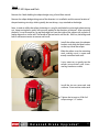
Installation
Instructions
Acura NSX
Rear
Big Brake Upgrade ST-40
and ST-10
98-055-1431-05
2/13/09
HIGH PERFORMANCE BRAKE SYSTEMS
APPLICATION DISCLAIMER
Caliper Clearance
Most 17” wheels will clear the outer diameter of the caliper of a 328mm brake kit. However, the more
critical clearance is the gap between the spokes of the wheel and the face of the caliper. Do not
assume a 19, 20 or even 24 inch wheel will clear the face of the caliper. The actual metal-to-metal
distance measured from the stock rotor face to the inside of the wheel spokes is 60.20 mm for the
328mm NSX Rear kit. We recommend at least 2mm of additional clearance. See the Wheel Fitment
Charts page on our website for more specific measurements at www.stoptech.com.
Final fitment of the wheel to the caliper is the responsibility of the customer.
Wheel Spacers
Wheel spacers can provide extra clearance to the outer face of the caliper. This will also space out
the entire wheel, widening the track width of the vehicle. Fender clearances should be checked on
lowered cars, and longer lug studs or wheel bolts are usually required. Note: The Wheel Industry
Council has issued guidelines advising wheel spacers not be used.
It is the responsibility of the customer to insure wheel spacers are properly
specified and installed.
Brake Vibration - THIS IS IMPORTANT!
The most common cause of brake vibration is improper bedding of pads and rotors or improper pad
selection for the specific driving environment. Rotor runout may also cause vibration, but precision
manufacturing and inspection typically means runout is not an issue. Double disc grinding insures
the rotor runout is within +/- 0.002” when installed on our aluminum hat and controls thickness
variation within 0.0003”. Under the most extreme conditions, any rotor may warp, but uneven pad
deposition is a more typical vibration cause. If the system is not properly bedded in, or street pads
are run on an open track, uneven pad deposits will occur causing an ever worsening vibration. Failure to immediately address a pad deposition/vibration issue may lead to permanent damage to the
rotors. Please read and understand the bed-in procedures included with this manual. If you have
any questions, please contact the StopTech Customer Service Department for assistance.
StopTech is not liable for vibrations caused by extreme usage or improper break-in
procedures.
Brake Noise
Certain brake pad compounds make more noise than others. Proper anti-squeal shim plates between
the caliper pistons and backing plate of the pad help reduce the problem. Anti-squeal lubricants
are also available to reduce some of the noise. The reality is, performance pads are more prone to
brake squeal.
The customer is responsible for any squeal related problems due to pad
selection.
2
Important Notices
Wheel Fitment:
Do not assume you wheels will fit. An outline drawing of your StopTech Big Brake
kit is included with this kit. Measure the distance from the outer face of your stock
rotor to the inner face of your wheel spokes and determine if a wheel spacer may
be necessary. DO THIS BEFORE YOU INSTALL YOUR KIT!
Cleaning of Rotors:
The AeroRotors supplied with this kit are coated with a rust inhibitor. This coating
MUST BE WASHED OFF WITH SOAP AND WATER before installation. After cleaning with
soap and water, a final cleaning with brake fluid will remove any residual contaminants.
Even if it doesn’t look as if anything is coming off the rotor, the rust inhibitor is there
and must be entirely cleaned. Rotors will start to rust without protection. If the rotor
is not rusty, it’s coated. After cleaning, you will likely see the rotor start to develop a
slight rust color. This is normal and desirable as it indicates all the rust inhibitor has
been removed.
Rotor and Pad Break-in:
Proper rotor and pad break-in is essential to the performance of your new brake system.
Failure to properly break-in the brakes will seriously impact how well they work and
how long they last. The number one cause of brake vibration is uneven pad material
deposition on the rotor. Proper break-in will greatly minimize such problems.
Follow the break-in procedures listed later in this manual as closely as possible.
If you have any questions about wheel fitment, rotor cleaning or
break-in of a particular pad type, please call our Tech Support Department @ 310-218-1091or you can e-mail directly to support@
stoptech.com
3
Acura NSX Rear Axle Kit
Safety Notice
Improper handling of a vehicle, especially while raised and supported by jack stands, ramps or other
mechanical means can cause serious bodily injury or even death. It is strongly recommended that
a trained, experienced mechanic, with proper equipment, install the Big Brake Kit as supplied by
StopTech. StopTech assumes no liability expressed or implied for the improper installation or use
of this product or its components. Liability No Warranty
Automobile racing and performance driving, whether sanctioned or not, on or off the street, is dangerous. Products used in such environments / applications are subject to stresses and conditions outside of normal use, wear and tear. All equipment sold or provided by StopTech is sold WITHOUT
WARRANTY, EXPRESSED OR IMPLIED. No warranty or representation is made to the product’s
ability to protect the user from injury or death. The user assumes all risk. StopTech is NOT responsible for any damage, consequential or otherwise for equipment failure or mal-performance after
installation. Under no circumstance are we liable for labor charges or loss of use.
Please, believe us, It will be better to read and understand this ENTIRE Installation Manual,
including the attached Break-in Procedures before starting the installation.
Tools and Equipment Required
Note: Some different models or years may use different size fasteners. Every effort has been taken to
correctly identify the proper size tool for each job. Occasionally, the manufacturer may use an alternate fastener. Check that each tool correctly fits the fastener before loosening or tightening.
17mm socket (1/2” drive suggested) or wrench
14mm wrench or socket
½” socket
11mm box wrench
10mm flare wrench
10mm wrench
Torque wrenches capable 8-55 lb-ft torque setting
6mm Allen (hex) wrench
5mm Allen (hex) wrench
Sheet metal snips
Small drip tray or several rags
Brake bleed bottle
Jack and stands suitable of safely supporting the vehicle
4
- DOT 3 or 4 Brake Fluid. Check manufactures recommendation for compatibility. StopTech recommends flushing brake fluid every 1-2 years, or more often under sever usage conditions. If not
done recently, the installation of a brake kit is an excellent opportunity to refresh your brake fluid.
Additional items you may need include:
- Adhesive backed lead wheel weights
This kit contains the following:
1 pair of ST-40, 4 Piston Calipers
1 pair of ST-10 Parking Calipers w/ pads
1 set of high performance brake pads
1 pair of 328 X 28mm AeroRotors™ and hat assemblies
1 pair of caliper adapter brackets for the ST-40 caliper
- 4ea. 7/16-20 Jet Nuts
- 4ea.12mm washers
1 set of stainless steel covered Teflon brake lines
- 1 pair of Banjo Bolts
- 2 pair of copper washers
- 1 pair of rubber end caps
1 pair of caliper adapter brackets for the ST-10 caliper (if parking brake option is supplied)
4 Shoulder Bolts
2 Parking Cable Bushings
Caliper, Hat and Bracket Finish Disclaimer: Many wheel-cleaning solutions contain strong
acids that may damage the finish on any caliper and aluminum anodized finish, especially the
plating on the hardware. Check for adverse effects by trying a small amount of the cleaner
in question on an inconspicuous area. Avoid over spraying, and rinse cleaning solutions off as
quickly as possible. StopTech will not be held liable for damage to caliper, hat or bracket finish
due to corrosive chemical exposure.
A level, stable and clean surface suitable for supporting the car
on jack-stands should be used for the installation.
Step 1
Place car in gear and block front wheels.
Break loose the lug nuts on both rear wheels before jacking up the car.
Refer to the Owners Manual for correct location for jacking up the vehicle. Jack up the vehicle and
secure on a pair of jack stands.
NEVER LEAVE ANY VEHICLE SUPPORTED WITH ONLY A
JACK, ALWAYS USE JACK STANDS.
5
As stated on the cover, this is a draft copy of the NSX Rear Install Manual. It does not
show removal of the stock brake line, caliper and rotor. If you are unsure of how to correctly remove the stock components, consult a qualified technician for assistance.
As a general rule, first disconnect the brake line from the chassis and use one of the
rubber caps supplied with the new brake lines to cap off the hard line to prevent brake
fluid from dripping. Remove the stock caliper with the stock brake line still attached
to the caliper.
If the rotor does not easily come off after removing the retaining screws, reinstall a
lug nut and tap the outer edge of the rotor with a non-marring mallet or hammer to
break it loose.
If there is a buildup of rust and corrosion on the hub, clean it with sandpaper, a wire
brush or other appropriate means before installing the new hat and rotor assembly.
6
Step 1
Remove Stock Caliper and Rotor
Note- At the time this manual was created, we did not have a vehicle in-house for the
photos. A display using the right rear corner from an NSX was used for the images.
In the near future, a more comprehensive manual will be created showing the actual
vehicle. Please refer to a Factory Service Manual or similar publication for removal
of the stock brakes and factory recommended torque values for noted fasteners. If
you have any questions, please contact our Customer Service Dept. at 310-325-4799
X 105 or e-mail: [email protected]
Step 2
Remove Dust Shield/Splash
Guard
Corner with caliper and rotor
removed
Using a 10mm wrench of socket, remove the four bolts holding the dust
shield in place.
7
Step 2 (continued)
Pull the shield away from the hub and
using a sheet metal snip, make a single
cut as shown.
After cutting the shield, bend the cut
section away and the shield will slide
off over the hub.
Hub and knuckle with shield
8
Step 3
Install Caliper Brackets
If you are running the StopTech parking brake kit, install the bracket for the ST-10
Parking Brake Caliper first, then the bracket for the ST-40 four piston caliper.
Using a 10mm socket, install the ST-10
parking caliper bracket using 2 of the
M6-1.0 X 16mm Hex Head Flange Bolts
provided. Do not tighten the bolts
until the ST-40 Bracket is also in place.
Using a 17mm wrench or socket, install the supplied M12-1.75 X 40mm
Hex Head Flange Bolts provided,
install the ST-40 bracket as shown.
Torque all bolts to the factory recommended specification.
If installing the kit without the parking caliper option, use the same supplied bolts for the ST-40
bracket and install as shown without the ST-10 bracket in place.
9
Step 4
Install Hat and Rotor Assembly
Rotors MUST be cleaned with soap and water prior to installation. Not
doing so will damage the rotors and pads and prevent the brakes from
performing properly.
Scrubbing the rotor with a Scotchbrite pad in soap and water
DO NOT SKIP THIS STEP!
Install hat and rotor assembly
and secure with the stock rotor
retaining screws.
Be sure the rotor assemblies
are on the correct side of the
car. Reversing the rotors will
severely decrease the cooling
capacity of the system. The
vanes inside the rotor should
lean to the rear of the car on
the top-side of the rotor. See
following pages.
10
11
ST-40 Caliper Component Identification
Bolt-in Bridge
Pad Retaining Clip
Cross Over Tube
Bleed Screw
Bridge Bolts
Use a light film of Anti-Seize on Bridge Bolt
shaft and threads
The ST-40 caliper uses a Porsche style pad.
The Friction Materials Standards Institute (FMSI) number for the pad backing plate is
D372
Please see the FAQ section of our website for further pad
interchange information. www.stoptech.com
12
Step 5
Install ST-40 Caliper and Pads
Remove the 2 bolts holding the caliper bridge using a 5mm Allen wrench.
Remove the caliper bridge taking note of the direction it is installed in and the correct location of the pad retaining wire clip, which typically, but not always, stays attached to the bridge.
Note- In order to stiffen the caliper, the bridge is a snug fit and the bolts may be tight when coming
out. Keep turning bolts gently with pressure applied in the direction of removal. After removing
the bolts, it may be necessary to tap the bridge out from the inside of the caliper with a plastic or
leather hammer or similar tool. The handle of the tool works well for this. With use, the bridge and
bolt fit will become easier to remove and install.
Install the caliper onto the adapter
bracket studs with the bleed screws
on the top side of the caliper.
Slide the caliper over the mounting
studs, making sure it is square and
evenly started on both studs.
It may necessary to gently tap the
caliper into position with a nonmarring hammer or mallet.
Install the Jet nuts onto each stud
with one 12mm washer under each
Tighten the Jet nuts to 45 lb-ft of
torque using a 1/2” socket.
13
Step 10
Install Brake Pads
Slide the pads into position through
the outboard side of the calipers.
Be sure the friction side of the pad is
facing the rotor (Yes, they have been
installed backward before).
Make sure the pad retention clip is
installed in the caliper bridge.
Reinstall the bridge by sliding it
straight into position and rocking it
until one of the bolt holes lines up.
It may be necessary to gently tap
the bridge into place with a plastic
or leather hammer. Apply a light
film of anti-seize to the threads and
shaft of each bridge bolt before assembly. Insert the first bolt and start
the first few threads using a 5mm
Allen wrench.
Note: The stainless steel wire pad-retaining clip will have a slight spring load when installed. This
load helps keep the pads away from the rotor when the brakes are released.
Gently press the opposite side of the
bridge with the palm of your hand, or
tap with a mallet until the second bolt
engages the hole. With pressure still
applied, start the second bolt. Torque
each bolt to approximately 8-10 lb-ft
of torque.
A torque wrench is typically not used
on the bridge bolts, a good mechanics feel helps assure the bolts are not
over tightened.
Do not over tighten the bridge
bolts, snug is tight enough.
WARNING: DO NOT HAMMER BRIDGE BOLTS INTO PLACE. Adjust position of bridge until bolts
slide in more easily.
14
Step 6
Install ST-10 Parking Caliper
Read Pages 15-21 before installing the ST-10
Parking Caliper
Position the Parking Caliper over
the rotor onto the bracket.
Place a few drops of 262 Loctite
onto the threads of the provided
shoulder bolts.
Slide the shoulder bolts through the
caliper bushings and thread into the
bracket.
Using a 6mm Allen wrench, torque
bolts to 50 lb-ft.
15
Place the parking brake cable
thru the bracket.
Place the bushing over the
cable.
Insert original cable clip over
bushing to secure the cable.
Rotate lever multiple times to
fully extend pads against the
rotor.
Install the lever return spring.
Using vise grip pliers rotate
the lever toward the cable
clevis.
16
Using vise grip pliers rotate
the lever toward the cable
clevis.
Insert the pin and pin retainer.
Be sure the cable is secured
away from any moving suspension or drive line components including when the car
is at ride height.
Note: The route of
the parking brake
line.
17
Also, the routing of the new stainless lines has not been photographed. Typically the
stainless line follows the same routing as the stock line.
An improperly routed brake line can lead to a catastrophic failure. It is the installers
responsibility to assure the line is properly and safely installed. Make sure the line is
not binding at any point of suspension travel and it stays clear of any moving suspension components such as springs, sway bars, CV boots, axles etc. If you are unsure of
the line routing, do not drive the car, please contact our Customer Service Dept. for
assistance.
Step 7
Install Stainless Brake Lines
Install the banjo bolt with a copper washer on each side
of the banjo fitting on the brake line, and thread into the
inlet port of the caliper.
Copper Crush Washer
Banjo Bolt
See notes on proceeding page for line routing.
After line is routed properly, torque the Banjo bolt to approximately 14 lb-ft. A torque
wrench is typically not used for the Banjo bolt, the feel of the copper washers crushing
will be a good indication of the approximate torque required.
18
Step 8
Bleed Brakes
Bleed the brake system using an 11mm wrench on the bleed screws:
- The sequence for bleeding the brakes should be:
1. Right outboard bleed screw
2. Right inboard bleed screw
3. Left outboard bleed screw
4. Left inboard bleed screw
Note: The calipers and lines will need to fill with fluid, quickly draining the master cylinder
reservoir. Keep a close watch on the fluid level when initially bleeding the system. Do not allow the
master cylinder reservoir to run dry and draw in air. Doing so may require the brake system to be
serviced by a certified brake technician. The reservoir location on the S4 is such that a small funnel
will make filling with brake fluid easier.
After bleeding, with a constant pressure applied to the brake pedal, check all connections for
leaks.
Brake fluid will damage most painted surfaces. Immediately clean spilled brake fluid from any
painted surface, including the caliper. Though caliper paint is designed to resist harsh chemicals,
prolonged exposure will damage the finish.
Step 9
Install Wheels
Check wheel to caliper clearance before installing wheels!
Carefully test-drive the vehicle in a safe area at low speed to insure all components are working
correctly. Follow pad and rotor break-in procedures on following page.
All trademarks are properties of their respective owners. StopTech is not associated or affiliated with
or sponsored by Acura.
19
AeroRotor Installation & Break-in Procedure
R
READ THIS NOW
FAILURE TO READ, UNDERSTAND AND FOLLOW THESE PROCEDURES WILL CAUSE PERMANENT DAMAGE TO YOUR BRAKE ROTORS AND KEEP THE SYSTEM FROM WORKING
AT IT’S FULL CAPACITY.
The majority of brake system problems are due to improper break-in of the rotors and pads. By
reading and understanding the following, you will avoid the most common causes of poor brake
performance and vibration. FAILURE TO READ AND UNDERSTAND THIS MAY CAUSE SERIOUS PERMANENT DAMAGE TO YOUR NEW ROTORS.
Wash Non-Plated AeroRotors with SOAP AND
WATER, then BRAKE CLEANER
before installation.
Non-plated AeroRotors are coated with a rust inhibitor that MUST be cleaned before use. A nonplated rotor looks like bare metal, while plated rotors are bright silver in color and do not need to
be washed. Even though you may not see a change in the rotor color, if the rotor is not rusty, the
rust inhibitor is there. Use soap and water, then brake cleaner to wash the rotors. A small piece of
Scotchbrite works well to scrub with in water. Use a clean paper towel as opposed to a shop towel
which may be contaminated, or let the brake cleaner run off the rotor surface. When cleaned and
rinsed properly, the surface of the rotor will soon show a light rust color, which is normal.
Break in your new brake system by carefully following the procedure
described below and on the opposite side of this page.
Breaking in rotors and pads is critical to the optimum performance of your new brakes. When breaking in new parts, you are not only heat cycling the pads, but depositing a layer of pad material onto
the rotor face as well. If not broken in properly, an uneven layer of pad material will be deposited
onto the rotor causing vibration. Virtually every instance of a “warped” rotor is attributed
to uneven pad deposition.
Note: Plated rotors must be driven with gentle braking until CAD plating is worn off rotor faces
BEFORE starting the break-in procedure. Do not use brakes aggressively until plating is worn off,
typically several miles of driving.
A moderate to heavy braking effort is needed to properly break in rotors and pads. If ABS intervention or lockup was called 100% brake effort, a stopping force of approximately 80-90 %, just short
of ABS intervention or lockup, is a general estimate of deceleration you are trying to achieve. Most
driver’s do not brake aggressively enough during bed-in.
(Please see other side)
20
Document: 98-300-0001
Rev. L 04-13-04
Rotor and Pad Break-in (continued)
NoteBedding of pads should not be done in wet weather or wet road conditions.
StopTech does not endorse speeding on public roads. If going above the
legal speed limit, do so in a safe area, away from traffic at your own risk.
After completing installation, make a series of 10 decelerations from 60 to 5-10 MPH. At the end
of each brake maneuver, immediately accelerate to 60 again for the next deceleration. Run all 10
brake maneuvers in one cycle. After cooling the system, run a 2nd cycle of 10 decelerations like
the first.
During the 60 to 5-10 MPH series of decelerations, the exact speed is not critical. Accelerate to
approximately 60 and begin the braking cycle. As you approach 5-10 MPH, it is not necessary to
watch the speedometer, keep your eyes on the road and approximate your speed at the end of each
deceleration. After the final deceleration of each cycle, drive as much as possible without using the
brakes to cool off the system. Ideally, the brakes should be allowed to cool to ambient temperature
before a second bed-in cycle. Plan your bed-in procedure so you do not have to stop with your foot on the pedal while the brakes
are hot. A level area is preferred and modulate any necessary stops by pulsing the brakes gently
and placing the car in neutral and/or using the parking brake. DO NOT COME TO A COMPLETE STOP
AND KEEP YOUR FOOT ON THE PEDAL WITH THE BRAKES EXTREMELY HOT, AS YOU WILL IMPRINT
PAD MATERIAL ONTO THE ROTOR, CAUSING A VIBRATION.
There are several indicators to look for while breaking in the system:
Expect there to be a distinct smell from the brakes. Smoke may be evident after several decelerations as well. Around the 5th slow down or later, some friction materials will experience “green
fade”. This is a slight fading of the brakes. The fade will stabilize, but not completely go away until
the brakes have cooled.
After the break-in cycles are finished, there will be a blue tint color on the rotor with a light gray film
on the rotor face. The blue tint indicates the rotor has reached the proper break in temperature and
the gray film is pad material starting to transfer onto the rotor face.
If Club Race type or higher performance pads are being used, add four decelerations from 80 to
5-10mph. These are added onto the end of the 60mph braking maneuvers, making each cycle a
total of 14 braking maneuvers for higher performance pads. Full race pads should not be driven on
the street and bed-in should be done at the track.
After the first break in cycle shown above, the brakes will still not be operating at their best capacity.
A second bed-in cycle is typically necessary before the brakes really start to “come in”. A “cycle” is a
series of stops with a cool down in between each cycle.
If you have any questions about rotor and pad break in, or any aspect of your StopTech brake kit
or brakes in general, please contact our Tech Support Department at 310-218-1091or e-mail us at
[email protected]
21