1
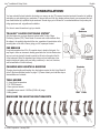
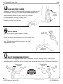
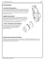
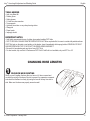
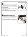
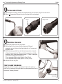
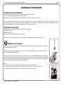
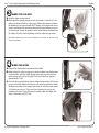
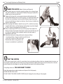
Juicy Seven, Juicy Carbon
& Juicy Five
Installation and Setup Guide
PLEASE READ THE SAFETY AND WARRANTY INFORMATION INSIDE
955-310588-000 Rev. C
© SRAM Corporation, 2006
JuicyTM Installation & Setup Guide
© SRAM Corporation • January 2006
English
2
JuicyTM Installation & Setup Guide
English
CONGRATULATIONS!
You have selected the best hydraulic disc brakes your money can buy! This manual contains important information for installing
and setting up and adjusting your new brakes. To ensure that your Avid Juicy brakes perform properly, we recommend that you
have them installed by a qualified bicycle mechanic. We also urge you to follow all of our recommendations to help make your
riding experience safe, enjoyable and troublefree.
First, here is some informations to get you started:
CPS
Hardware
TRI-ALIGNTM CALIPER POSITIONING SYSTEMTM
Avid disc brakes use a unique alignment system called Tri-align Caliper
Positioning System (CPS). These stacks of concave and convex washers allow
the caliper to be perfectly aligned with the rotor, regardless of imperfections in the
mounting tabs on the fork or frame, giving you full, square pad contact.
PAD BREAK-IN
It may take anywhere from 20 to 40 complete stops to break in Avid pads. You
may begin to notice an increase in braking power after the first ride. Brake noise
can occur not only during the break-in period but off and on throughout the life
of the brake pads. Noise is dependent upon factors such as brake setup, rider
weight, riding style, braking style, and riding conditions (i.e. dust, soil, moisture,
and contamination of friction surfaces).
CHANGING HOSE LENGTHS & BLEEDING
CPS Bolt
Brackets
Changing hose lengths and bleeding Juicy disc brakes requires the Avid Juicy Bleed Kit
(refer to the hose and bleed section on page 11.) Please contact your local bike shop or
www.avidbike.com for details.
TOOLS NEEDED
• 2, 4 and 5mm hex wrenches
• T-25 TORX® wrench
• 10mm open-end wrench
• Adjustable torque wrench: 2.8-10Nm (25-90 in-lb) range
• Safety glasses
Rear
Front
MAKE SURE YOU HAVE THE RIGHT BRACKETS
0
20
2.
30
3. t t
37 on n
.5 Fr ou
11 03 t M
2 os
P
0
30
2.
30
2. t t
37 on n
.5 Fr ou
11 85 t M
1 os
P
0 d
90 de
2. tru
30 x
6. t E
37 on
.5 Fr
11 0
16
0
50 d
2. rge
10 o
6. t F
37 on
.5 Fr
11 0
16
00 d
-9 ge
02 or
21 t F
37 on
5- Fr
11 5
18
0
80 d
2. rge
10 o
3. t F
37 on
.5 Fr
11 03
2
00 r
-6 xe
02 ox
35 t B
37 on
5- Fr
11 03
2
00
-3 20
02 R
36 t Q
37 on
5- Fr
11 03
00 ed
2
-6 ud
02 xtr
64 r E
37 a
5- Re
11 60
1
00 d
-2 ge
02 or
62 r F
37 a
5- Re
11 60
00 d
1
-6 ge
02 or
22 r F
37 a
5- Re
11 5
18
00 d
-5 ge
02 or
32 r F
37 a
5- Re
11 03
2
© SRAM Corporation • January 2006
3
JuicyTM Installation & Setup Guide
English
SAFETY INFORMATION
Brakes are a safety-critical item on a bicycle. Improper setup
or use of brakes can result in loss of control or an accident,
leading to a severe injury.
Juicy disc brakes are designed as a system. Do not use
components from a manufacturer other than Avid within the
system.
Avid brakes are a performance product that offer increased
stopping power over brakes that you may be use to. This
greater power requires less effort to lock-up a wheel when
braking. A wheel lockup might cause you to lose control and
possibly cause injury.
Avid disc brake rotors are compatible with 44mm, 6-bolt
international standard disc hubs.
It’s your responsibility to learn and understand proper braking
techniques. Consult the owner’s manual for your bicycle and
a professional bike dealer.
Practice your riding and braking techniques on a flat and
level surface prior to aggressive riding.
The effectiveness of braking is dependent on many
conditions over which SRAM has no control. These include
the speed of the bicycle, type and condition of riding surface,
braking lever force, proper installation and maintenance of
brakes, brake lines, hydraulic fluid, levers, brake pads,
condition of the bike, weight of the rider, proper braking
techniques, weather, terrain, and a variety of other factors.
We recommend 32 or 36-spoke wheels with a 3 or 4
cross spoke lacing pattern. Contact your specific wheel
manufacturer for more specifications.
DO NOT USE RADIALLY SPOKED WHEELS.
USE ONLY DOT 4 OR DOT 5.1 FLUIDS WITH JUICY DISC
BRAKES.
Do not use a fluid other than the DOT fluids suggested.
Doing so will damage the system and make the brakes
unsafe to use.
DOT fluids will damage painted surfaces. If any fluid comes
in contact with a painted surface (i.e. your frame), wipe it off
immediately and clean with isopropyl alcohol.
Do not allow any brake fluid to come in contact with the
brake rotors. If this occurs, clean the rotors with isopropyl
alcohol.
Avid brakes and levers are not intended for use on any
motorized bicycle or vehicle. Such use could result in a
serious personal injury.
Do not allow any brake fluid to come in contact with the
brake pads. If this occurs, the pads are contaminated and
must be replaced.
ALWAYS RIDE UNDER CONTROL
Remember, it takes longer to stop in wet conditions. To
reduce the possibility of an accident and minimize trail
erosion, you should avoid locking-up your wheels.
WARNING
Do not touch the braking surface of any rotor with your
bare hands, because the oils from your fingers will degrade
its performance. Always wear gloves, or handle the rotor by
its spokes.
© SRAM Corporation • January 2006
Disc brakes become very hot during use. Do not touch the
caliper or rotor immediately after use. Make sure the brake
has cooled down before making any adjustments.
955-310588-000 Rev. C
JuicyTM Installation & Setup Guide
1
English
INSTALL ROTOR
Mount the rotor to the hub using the supplied T-25 TORX® bolts and tighten to the
specified torque. Avid logo MUST face out. Install the wheel into the fork or frame.
TORQUE TO:
6.2 Nm (55 in-lb)
2
MOUNT FRONT CALIPER
Mount the front caliper (shorter hose) to the fork.
POST MOUNT
INTERNATIONAL STANDARD (IS) MOUNT
OR
Remove...
...then mount direct
TORQUE TO:
9-10 Nm (80-90 in-lb)
Loosen before
mounting
Snug, then back off
1/8th to 1/4th turn
IS MOUNT
Loosen the CPS bolts, then bolt the caliper to the mounting
tabs. Tighten the mounting bolts to the specified torque.
Check that the caliper moves freely on the CPS hardware.
© SRAM Corporation • January 2006
POST MOUNT
Remove the mounting bracket but leave the CPS bolts and
washer stacks intact. Bolt the caliper directly to the fork. Snug
the bolts, then back them out 1/8th to 1/4th turn. Check that
the caliper moves freely on the CPS hardware.
5
JuicyTM Installation & Setup Guide
3
English
Loosen before
mounting
MOUNT REAR CALIPER
Loosen the CPS bolts, then mount the rear caliper (longer hose) to the I.S. tabs
on the rear of the bike. Tighten the mounting bolts to the specified torque.
Check that the caliper moves freely on the CPS hardware.
TORQUE TO:
5-7 Nm (40-60 in-lb)
4
ADJUST HOSE ANGLE, THEN ROUTE
If necessary, slightly loosen the banjo bolts on the calipers with an
8mm open-end wrench and rotate the fittings for optimal routing.
Re-tighten the banjo bolts to the specified torque, then route the
hoses. Make sure there is enough hose at critical points to allow for
suspension movement, but also make sure there aren’t any big loops
of extra hose. Now, secure the hoses to the frame and fork.
NOTE: IF YOU NEED TO SHORTEN THE HOSE, PLEASE REFER TO THE “HOSE
LENGTH ADJUSTMENT” SECTION OF THIS GUIDE (PAGE 11).
© SRAM Corporation • January 2006
If necessary, loosen
slightly and rotate for
good routing
RE-TORQUE TO:
5.5-6.2 Nm
(50-55 in-lb)
955-310588-000 Rev. C
JuicyTM Installation & Setup Guide
5
English
MOUNT LEVERS: Juicy Seven
MOUNT LEVERS: Juicy Five
Mount the levers onto the handlebar in the proper position.
Arrows must point up. Make sure there is enough hose for
the handlebar to turn freely side to side. Tighten the
top bolt completely to the specified torque so there
is no gap. Tighten the bottom bolt to the same torque.
Slide the lever onto the bar to the proper position.
Tighten the clamp bolt to the specified torque.
Do not overtighten.
TORQUE TO:
4-5 Nm
(30-40 in-lb)
Mount levers with
arrows facing up
No Gap
TORQUE TO:
2.8-3.4 Nm
(25-30 in-lb)
Gap
Check that the bars turn freely.
If there is excess hose in this
area, see the instructions on
changing hose lengths and
bleeding the system
5a
RIGHT-HAND FRONT (optional)
To run moto-style (right-hand front), remove the E-Clip from the bottom of the pivot assembly. Then remove the Speed Dial knob,
remove the bushing, and swap. Replace the E-Clip. Flip the clamps over so the arrows face up, then mount as in step 5.
NOTE: JUICY FIVE CAN BE RUN EITHER
LEFT OR RIGHT, JUST SWAP THE LEVERS
AND INSTALL THE CLAMP BOLTS
Flip the clamps
then mount
Swap
FROM THE OPPOSITE SIDE.
Remove,
then re-install
© SRAM Corporation • January 2006
955-310588-000 Rev. B
JuicyTM Installation & Setup Guide
6
English
ALIGN AND TRUE CALIPERS
Squeeze the front lever 5 or 6 times, then hold. Compress the lever (with your hand
or a rubber band), then snug the CPS bolts enough to hold the caliper in place.
TORQUE TO:
8-10 Nm
(70-90 in-lb)
Spin the wheel and check for rotor drag. If there is drag, loosen the
CPS bolts and repeat. Once there is no drag, torque the CPS
bolts in an alternating fashion to the specified torque.
Repeat the procedure for the rear brake.
7
ADJUST REACH
Use a 2mm hex wrench to adjust the reach if necessary.
One click equals 1mm of adjustment.
(in an alternating fashion)
One “click” of the
2mm hex reach
adjust screw here...
If using twist-shifters, it will be necessary to slide the levers away from
the shifters or remove them completely to access the reach adjustment
screw. Re-torque the lever clamp bolts as noted in step 5 after
adjusting the lever reach.
...equals 1mm of
adjustment here
8
ADJUST PAD ENGAGEMENT POINT
Use the Speed Dial pad engagement knob to adjust the engagement point exactly where you want it. Turning the knob
towards the stem decreases the amount of lever travel necessary for the pads to contact the rotor. Experiment, and see
what different settings feel like. The goal is for your brake pads to engage right where your grip on the lever feels the strongest.
This way for quicker
engagement
This way for quicker
engagement
Right
Left
Note: The Speed Dial knob can turn a total of 20 revolutions
© SRAM Corporation • January 2006
955-310588-000 Rev. C
JuicyTM Installation & Setup Guide
English
PAD REPLACEMENT
1. PUSH THE PISTONS BACK IN
As the Juicy calipers are self-adjusting, the pistons need to be pushed back into the
body to their original position before the new pads can be installed. The safest way to
do this is with the old pads still in the caliper to protect the pistons. Place a flat-blade
screwdriver between the old pads, then carefully rock it back and forth, pushing the
pistons back into their bores.
2. REMOVE THE OLD PADS
Grab one of the pad tabs and slide the pad toward the center of the caliper (this
disengages the pad backing plate from the post in the center of the piston), then
pull the pad straight out. Repeat for the other pad. NOTE: The spreader clip that
sits in between the pads may not come out with the second pad. If not, push
it out from the open top of the caliper with your little finger.
3. INSTALL THE NEW PADS AND SPREADER
Be sure the spreader clip is oriented to the pads as shown
below. Squeeze the pad and clip assembly together, then
insert into the caliper as a unit. Firmly push until the
assembly “clicks” into place.
CHANGING HOSE LENGTHS AND BLEEDING
Juicy brakes come with hoses already attached in an “average” length. The system has already been bled, so if you do not
need to change the hose length, then you are ready to ride. If, however, you do need to change hose lengths, then follow
the simple procedure outlined next in this manual.
© SRAM Corporation • January 2006
9
JuicyTM Hose Length Adjustment and Bleeding Guide
© SRAM Corporation • January 2006
English
10
JuicyTM Hose Length Adjustment and Bleeding Guide
English
Hose Length Adjustment
and Bleeding
Juicy brake kits come with hoses already attached in an “average” length.
The system has already been bled, so if you do not need to change
the hose length, then you are ready to ride. If, however, you do need to
change hose lengths, then follow this simple procedure.
© SRAM Corporation • January 2006
11
JuicyTM Hose Length Adjustment and Bleeding Guide
English
INTRODUCTION
Bleeding is one of the most important steps in topping off the performance of any hydraulic brake system. Any air inside a
hydraulic brake system degrades the performance of the brake. The goal of bleeding is to remove the air that’s trapped in the
hoses, caliper or lever. When you bleed Juicy brakes you remove more air than any other brake’s bleeding procedure does.
That’s one of the reasons why Juicy brakes are the most powerful and precise hydraulic brakes on the market.
Note: Juicy brakes come with hoses
attached and bled. If you don’t need to
change the hose length, then you
should not need to bleed the system
again.
Crow’s foot
wrench
Compression
fittings
To properly perform a Juicy bleed,
you will need a Juicy Bleed Kit
which contains:
Hosebarbs
Avid Hi-Performance
DOT Fluid
Syringes
Torx® wrench
Here are the parts that you’ll be dealing with in the hose adjustment and bleeding process:
Caliper bleed-port screw
Lever bleed-port screw
Compression
fitting
Hosebarb
Hose
Boot
© SRAM Corporation • January 2006
Compression
nut
955-310588-000 Rev. C
JuicyTM Hose Length Adjustment and Bleeding Guide
English
TOOLS NEEDED
• Avid Juicy Bleed Kit
• Rubber gloves
• Safety glasses
• 2.5 and 4mm hex wrenches
• Torque wrench
• Hydraulic line cutters or very sharp housing cutters
• Sharp pick
• Paper towels
• Isopropyl alcohol
IMPORTANT NOTES
• Avid highly recommends the use of rubber gloves when handling DOT fluids.
• DOT FLUIDS WILL DAMAGE PAINTED SURFACES! DO NOT allow any brake fluid to come in contact with painted surfaces.
If DOT fluid gets on the paint or pad printing on the brakes, clean it immediately with isopropyl alcohol. REMOVAL OF PAINT
AND/OR PRINTING BY DOT FLUID IS NOT COVERED UNDER WARRANTY!
• Be careful to keep brakes pads and rotors free of DOT fluid.
• For best results, only use Avid Hi Performance DOT Fluid! If Avid fluid is not available, only use DOT 4 or 5.1!
CHANGING HOSE LENGTHS
1
RE-CHECK HOSE ROUTING
Since you can’t lengthen the hose after you have cut it, take a moment and
re-check the routing of the hoses. Be sure to account for suspension movement
and check that the bars turn freely by turning the bars all the way from side to
side. Make sure the hoses are properly secured as well.
© SRAM Corporation • January 2006
13
JuicyTM Hose Length Adjustment and Bleeding Guide
English
2
REMOVE HOSE FROM LEVER
A. Pull the boot away from the lever, then use the crow’s foot wrench (included)
to unscrew the hose compression nut. If the boot sticks, carefully pull a corner
of the boot up with something that won’t harm it (like a pencil tip) and spray a
little alcohol between the boot and the lever. Once you work the alcohol in a
little, the boot should loosen up.
B. Pull the hose from the lever. Wiggle the hose if necessary. Be careful, to spill
as little DOT fluid as possible. Any DOT that drips out will create bubbles that
you’ll have to eliminate later.
C. Slide the nut and boot down the hose and away from the end where you’ll be
cutting. Be careful not to engage the lever while the hose is removed.
3
DETERMINE PROPER HOSE LENGTH & CUT
A. Determine where you need to cut the hose by holding it up to the lever in the
position you’d like it. The groove in the lever nose marks the spot where you’ll
cut the hose. Make sure to leave a gentle curve in the hose–with enough
length to freely turn the bars. Double-check this part, because
you can’t go back after you cut.
B. Cut the hose using hydraulic hose cutters (very sharp cable-housing cutters).
MEASURE
© SRAM Corporation • January 2006
TWICE, CUT ONCE!
955-310588-000 Rev. C
JuicyTM Hose Length Adjustment and Bleeding Guide
English
4
INSTALL NEW FITTINGS
A. While holding the hose firmly, thread a new hosebarb into the end of the hose using a 2.5mm hex wrench.
B. Slide a new compression fitting over the end of the hose with the new hosebarb.
No gap
Ready to install
5
RE-INSTALL THE HOSE
A. Push the hose firmly into the lever until it stops.
B. While holding the hose in place, slide the compression fitting and
compression nut up to the lever, then finger-tighten the nut. You may need
to wiggle the hose.
C. While continuing to push the hose into the lever body, use the nut wrench
to tighten the compression nut. When you feel the compression nut hit the
compression fitting, tighten approximately another 1 1/2 turns, at which point
you will feel the compression nut bottom out.
• If your compression fitting is alloy, tighten to 5 Nm (47 in-lb).
• If your compression fitting is steel, tighten to 7.8 Nm (70 in-lb).
D. Slide the boot back into place
TIME TO BLEED THE BRAKES
Cutting down the hose introduces a small amount of air into the system, so
at this point it is necessary to bleed the brakes for optimal performance. See the
next section, “Bleeding Procedure.”
CROW’S
FOOT TO BE
90°
TO
TORQUE WRENCH
© SRAM Corporation • January 2006
15
JuicyTM Hose Length Adjustment and Bleeding Guide
English
BLEEDING PROCEDURE
INTRODUCTION TO BLEEDING
When bleeding Juicy brakes, there are two main points to keep in mind:
1. You are simply chasing bubbles out of the system
2. Gravity is your friend. (Liquid is heavier than gas, so bubbles always tend to rise.)
Avid’s bleeding procedure allows the isolation of the caliper so it can be bled completely air free. Then, by pushing fluid from the
caliper up to the lever, you remove any air in the hydraulic line. From there, it’s just a matter of purging those bubbles out of the
reservoir. Bleeding isn’t hard once you understand what you are trying to do.
PROCEDURE OVERVIEW
You will perform 3 basic operations when bleeding Juicy brakes:
1. Bleed the caliper
2. Bleed the hose
3. Bleed the lever (master cylinder and reservoir)
Following this procedure gives you a perfectly bled, optimally performing Juicy brake. Enjoy!!
1
PREPARE THE SYRINGES
A. Fill one syringe 1/2 full with Avid Hi-Performance DOT Fluid and close the hose clamp. Leave the
other syringe empty and open.
B. Now you are going to de-gas the fluid in the 1/2 full syringe. Getting all the air out of the fluid now
gives you the ultimate brake bleed.
Leave the hose clamp shut and pull down on the plunger. You will see bubbles appear from nowhere in
the fluid. That’s all air that was trapped in the fluid. Pull on the plunger several times. When the bubbles
stop forming, open the clamp and carefully push the excess air and gas out. Try tapping the syringe as
you pull, to release more bubbles. Repeat several times.
Notes:
• Be careful not to pull too hard or you will pull air past the seal of the syringe.
• You never eliminate all the bubbles in the fluid, so after you have pulled a few times, and
the number of bubbles decreases, you are ready to move on to the next step.
© SRAM Corporation • January 2006
955-310588-000 Rev. C
JuicyTM Hose Length Adjustment and Bleeding Guide
2
English
PREPARE THE CALIPER AND THE LEVER
ON THE CALIPER
A. Use the T-10 Torx wrench to remove the caliper bleed port screw from the
center of the banjo bolt.
B. Make sure the fluid in the 1/2-full syringe is pushed all the way to the tip
(no air gap!), then screw into the caliper bleed port.
ON THE LEVER
A. Juicy Seven ONLY: turn the pad contact knob all the way to the “out”
position. For a left lever, this would be all the way clockwise and for a right
lever all the way counterclockwise.
B. Using a 4mm hex wrench, slightly loosen the lever clamp bolt(s) then rotate
the lever so the body of the lever points straight down – perpendicular with
the floor. You will need to loosen your shifter to allow the brake
lever down to this position.
C. Remove the lever bleed port screw and install the empty syringe, leaving the
clamp on the syringe open.
D. Squeeze the lever closed (against the bar) and fasten it with a rubber band.
This closes off the master cylinder and isolates the caliper, allowing the
removal of any air from the caliper only before moving on to the rest of
the system.
IMPORTANT: ENSURE THAT THE
REACH ADJUSTER IS NOT ADJUSTED SO FAR OUT
THAT THE LEVER BLADE IS BOTTOMED OUT ON THE LEVER BODY.
DOING
SO CAN MAKE
BLEEDING THE BRAKE IMPOSSIBLE.
© SRAM Corporation • January 2006
17
JuicyTM Hose Length Adjustment and Bleeding Guide
English
3
BLEED THE CALIPER
A. Open the caliper syringe clamp
B. Gently push the syringe plunger out with your thumb. If there is air in the
caliper, this draws it back into the syringe. Release the plunger to replace
the bubbles you just removed with fluid. Tapping on the caliper with a nonmarring instrument while performing this process helps bubbles move out
into the syringe. Repeat the process until no more bubbles are drawn from
the caliper. Once this is accomplished, close the caliper syringe clamp.
NOTE: BE
CAREFUL NOT TO PULL THE PLUNGER OUT TOO HARD, OR YOU WILL SUCK
AIR PAST THE SEALS.
4
BLEED THE HOSE
A. Remove the rubber band to release the lever blade.
B. While holding the caliper syringe up to prevent bubbles from floating back
into the system, open the caliper syringe clamp and force fluid from the
caliper syringe up to the lever syringe. Do this until the lever syringe is
approximately 1/4 full.
C. Close the lever syringe clamp, then the caliper syringe clamp. At this point,
you are done at the caliper end. Remove the caliper syringe and re-install
the bleed port screw. Have a paper towel ready to catch any small amount
of fluid that may come out of the port when removing the syringe and
reinstalling the screw. Once the screw is installed, wash the caliper with
water to deactivate any DOT fluid.
© SRAM Corporation • January 2006
955-310588-000 Rev. C
JuicyTM Hose Length Adjustment and Bleeding Guide
English
5
BLEED THE LEVER (Master Cylinder and Reservoir)
A. Draw a gentle vacuum on the lever syringe by pulling on the syringe plunger.
This pulls air bubbles out of the reservoir. Release the plunger to replace the
bubbles you just removed with fluid.
B. Tapping on the lever with a non-marring instrument while performing this
process helps bubbles move out into the syringe. You should also sqeeze the
lever (like you are braking) a few times while bleeding. Repeat the process
until no more bubbles are drawn from the lever. Once the lever is bubble free,
close the syringe clamp.
C. With the syringe still attached, rotate the lever up 90°, so that the lever body
is parallel with the floor, and the bleed port (and syringe) are pointed straight
up. Now, unscrew the syringe from the bleed port.
D. Place a couple drops of DOT fluid on top of the open port and replace the
bleed port screw. Have a paper towel ready to wick up any fluid that may well
up in the port. Once the screw is installed, wash the lever with water to
deactivate any DOT fluid.
E. Rotate the lever back to riding position and re-torque as follows:
• Juicy Seven/Carbon: Torque to 2.8-3.4 Nm (25-30 in-lb)
• Juicy Five: Torque to 4-5 Nm (30-40 in-lb)
Rotate shifters back to riding position and
re-torque to manufacturer’s specifications.
6
TEST THE SYSTEM
You are almost ready to ride, but first it’s a good idea to test your brakes by pulling on the lever extremely hard (as hard as you
can imagine yourself pulling the lever while you’re riding) several times. Make sure and look around the hose nut on the lever,
and the banjo bolt on the caliper for any leaks. Make one last check of all the bolts and fittings.
If everything checks out, YOU ARE READY TO RIDE!
Empty the syringes into a sealed container and dispose of the fluid properly.
DO NOT RE-USE THIS FLUID!
DO NOT LEAVE THE HOSE CLAMPS CLOSED (this will damage the clear tubing on the syringes)!
© SRAM Corporation • January 2006
19
JuicyTM Installation & Setup Guide
English
SRAM CORPORATION WARRANTY
EXTENT OF LIMITED WARRANTY
SRAM warrants its products to be free from defects in materials or
workmanship for a period of two years after original purchase. This
warranty only applies to the original owner and is not transferable.
Claims under this warranty must be made through the retailer where the
bicycle or the SRAM component was purchased. Original proof of
purchase is required.
LOCAL LAW
This warranty statement gives the customer specific legal rights. The
customer may also have other rights which vary from state to state
(USA), from province to province (Canada), and from country to
country elsewhere in the world.
To the extent that this warranty statement is inconsistent with the local
law, this warranty shall be deemed modified to be consistent with such
law, under such local law, certain disclaimers and limitations of this
warranty statement may apply to the customer. For example, some
states in the United States of America, as well as some governments
outside of the United States (including provinces in Canada) may:
a.Preclude the disclaimers and limitations of this warranty
statement from limiting the statutory rights of the consumer
(e.g. United Kingdom).
b.Otherwise restrict the ability of a manufacturer to enforce such
disclaimers or limitations.
LIMITATIONS OF LIABILITY
To the extent allowed by local law, except for the obligations specifically
set forth in this warranty statement, In no event shall SRAM or its thirdparty suppliers be liable for direct, indirect, special, incidental, or
consequential damages.
LIMITATIONS OF WARRANTY
• This warranty does not apply to products that have been incorrectly
installed and/or adjusted according to the respective SRAM technical
installation manual. The SRAM installation manuals can be found online
at www.SRAM.com, www.rockshox.com or www.avidbike.com.
• This warranty does not apply to damage to the product caused by a
crash, impact, abuse of the product, non-compliance with manufacturer’s
specifications of usage or any other circumstances in which the product
has been subjected to forces or loads beyond its design.
• This warranty does not apply when the product has been modified.
• This warranty does not apply when the serial number or production
code has been deliberately altered, defaced or removed.
• This warranty does not apply to normal wear and tear. Wear and tear
parts are subject to damage as a result of normal use, failure to service
according to SRAM recommendations and/or riding or installation in
conditions or applications other than recommended.
© SRAM Corporation • January 2006
WEAR AND TEAR PARTS ARE IDENTIFIED AS:
- Dust seals
- Bushings
- Air sealing o-rings
- Glide rings
- Rubber moving parts
- Foam rings
- Rear shock mounting hardware
and main seals
- Stripped threads/bolts (aluminum,
titanium, magnesium or steel)
- Upper tubes (stanchions)
- Brake sleeves
- Brake pads
- Chains
- Sprockets
- Cassettes
- Shifter and brake cables (inner
and outer)
- Handlebar grips
- Shifter grips
- Jockey wheels
- Disc brake rotors
- Tools
• This warranty shall not cover damages caused by the use of parts of
different manufacturers.
• This warranty shall not cover damages caused by the use of parts that
are not compatible, suitable and/or authorized by SRAM for use with
SRAM components.
SRAM Corporation
1333 North Kingsbury, 4th Floor, Chicago, Illinois 60622
1-312-664-8800 • fax 1-312-664-8826
www.avidbike.com
955-310588-000 Rev. C