1
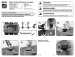
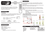
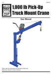
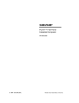
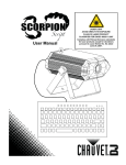
Hydraulic
Floor Jack Combo
Operating Instructions & Parts Manual
Capacity
2 Ton
Model Number
F-2330BMC
Lifting range for Floor Jack: 5-1/4” ~ 13”
Support range for Jack Stands (per pair): 10-1/2”~16-3/4”
! WARNING
To avoid crushing and related injuries:
• NEVER work on, under or around a
load supported only by a hydraulic jack.
• ALWAYS use a pair of appropriately
rated jack stands.
SFA Companies, Inc.
10939 N. Pomona Ave.
Kansas City, MO 64153
Phone (816)891-6390, Fax (816)891-6599
Printed in China
F-2330BMC-M0_012012
2 Ton Floor Jack
BEFORE USE
Save these instructions. For your
safety, read, understand, and follow the
information provided with and on this
jack. The owner and operator of this
equipment shall have an understanding
of this jack and safe operating procedures
before attempting to use. The owner and
operator shall be aware that use and
repair of this product may require special
skills and knowledge. Instructions and
safety information shall be conveyed in
the operator’s native language before
use of this jack is authorized. If any doubt
exists as to the safe and proper use of this
jack, remove from service immediately.
Inspect before each use. Do not use if
broken, bent, cracked, or damaged parts
(including labels) are noted. Any jack that
appears damaged in any way, operates
abnormally or is missing parts, shall be
removed from service immediately. If
the jack has been, or suspected to have
been subjected to a shock load (a load
dropped suddenly, unexpectedly upon
it), immediately discontinue use until jack
has been checked by a factory authorized
service center. It is recommended that an
annual inspection be done by qualified
personnel. Labels and Owner’s Manuals
are available from the manufacturer (see
Replacement Parts, page 6).
1. Verify that the product and the
application are compatible, if in doubt
call Pro-Lift Customer Support @
(888) 332-6419.
2. Before using this product, read the
owner ’s manual completely and
familiarize yourself thoroughly with the
product, its components and recognize
the hazards associated with its use.
3. Using the stamped end of the provided
handle, engage and turn the release
valve counterclockwise no more
than 1/2 full turns from a fully closed
position.
4. With saddle fully lowered, locate and
remove the oil filler plug. Insert the
handle into the handle sleeve, then
pump 6 to 8 full strokes. This will help
release any pressurized air which may
be trapped within the reservoir. Oil
level should be ~3/16” above the inner
cylinder as seen from the oil filler plug
hole. Reinstall the oil filler plug.
5. Check to ensure that jack rolls freely
(if so equipped) and that the pump
operates smoothly before putting into
service. Replace worn or damaged
parts and assemblies with factory
Authorized Replacement Parts only.
(See Replacement Parts Section).
Lubricate as instructed in Maintenance
Section.
PRODUCT DESCRIPTION
Pro-Lift Floor Jack is designed to lift, but
not sustain, rated capacity loads. It is
designed to be used in conjunction with
jack stands. Pro-Lift Floor Jack has a
unique feature which provides fast, no
load lifts to the jacking point. Intended
use: To lift one wheel or axle of a vehicle
for the purpose of service and/or repair
of vehicle components. After lifting, loads
must be immediately supported by a pair
of appropriately rated jack stands. Check
with vehicle owner’s manual for proper
lift points.
2
! ADVERTENCIA
! WARNING
Estudie, entienda y sega todoslos
materiales impresos con / para este
producto antes de su uso. No exceda
la capacidad nominal. Se trata de un
dispositivo de elevación solamente!
Inmediatamente después de levantar,
soporte la carga con un par de
soportes de elevación adecuadamente
evaluados. Use sólo en superficie duros
y nivel. Ascensor sólo en las zonas del
vehículo según especificado por el
fabricante del vehículo. No se harán
cambios a este producto. Si no prestar
atención a las marcas puede resultar
en lesiones personales y / o daños a la
propiedad.
Study, understand, and follow all
instructions before operating this
device. Do not exceed rated capacity.
Use only on hard, level surface. Lifting
device only. Immediately after lifting,
support the vehicle with appropriate
means. Do not move or dolly the
vehicle on the jack. Lift only on areas of
the vehicle as specified by the vehicle
manufacturer. No alteration shall be
made to this product. Failure to heed
these markings may result in personal
injury and/or property damage.
! ADVERTISSMENT
Assurez-vous de bien lire, de
comprendre, et de suivre toutes les
instructions avant d’utiliser ce dispositif.
Ne dépassez pas la capacité nominale
spécifiée. Utilisez sur un sol plat et
stable. C’est un dispositif de levage
seulement. Après le levage, transférez
immédiatement la charge sur une paire
de béquilles de cric de véhicule ayant
la capacité nominale appropriée.Il est
interdit de modifier ce dispositif. Le
levage doit s’effectuer seulement aux
endroits du véhicule spécifiés par le
fabriquant du véhicule. Respectez les
mises en garde et avertissements de
ce guide sous peine de provoquer des
blessures personnelles ou de causer
des dégâts matériels.
! CAUTION
Be sure all tools and personnel are clear
before lowering load. No alterations
shall be made to this device. Only
attachments and/or adapters supplied
by the manufacturer shall be used. Lift
only on areas of the vehicle as specified
by the vehicle manufacturer.
3
OPERATION
Lowering
Lifting (refer to Fig 1)
1. Place vehicle in park, with emergency
brake on and wheels securely
chocked to prevent inadvertent vehicle
movement.
2. Close release valve by turning handle
clockwise until firm resistance is felt
Center jack saddle under lift point.
3. Verify lift point, then pump handle until
saddle contacts lift point. To lift, pump
handle until load reaches desired
height.
4. Transfer the load immediately to
appropriately rated jack stands (always
use in pairs).
1. Raise load high enough to clear jack
stands, then carefully remove jack
stands.
2. Slowly turn the handle counterclockwise,
but no more than 1/2 full turn. If the load
fails to lower:
a. Use another jack to raise the
vehicle high enough to reinstall jack
stands.
b. Remove the affected jack and then
the stands.
c. Using the other jack, lower the load
by turning the operating handle
counterclockwise, but no more than
1/2 full turn.
3. After removing jack from under the
load, push saddle down to reduce ram
exposure to rust and contamination.
Cover plate
(Remove to access
oil filler plug)
Oil filler plug
(Not shown, on
reservoir)
Lifting arm
Saddle
Handle
sleeve
Front
wheel
Release
valve
Caster
Jack handle
Engage
release valve
with this end
Figure 1 - Typical Floor Jack Nomenclature
4
MAINTENANCE
MAINTENANCE (continued)
Important: Use only a good grade
hydraulic jack oil (e.g. Mobil DTE 13M or
equivalent). Avoid mixing different types
of fluid and Never use brake fluid, turbine
oil, transmission fluid, motor oil or glycerin.
Improper fluid can cause failure of the
jack and the potential for sudden and
immediate loss of load.
2. Lay the jack on its side and drain the
fluid into a suitable container.
Note: Dispose of hydraulic fluid in
accordance with local regulations.
3. Fill with oil until ~3/16” above the inner
cylinder as seen from the oil filler plug
hole. Reinstall the oil filler plug.
Lubrication
A periodic coating of light lubricating oil
to pivot points, axles and hinges will help
to prevent rust and assure that wheels,
casters and pump assemblies move
freely.
Adding oil
1. With saddle fully lowered set jack in
its upright, level position. Locate and
remove oil filler plug.
2. Fill with oil until ~3/16” above the inner
cylinder as seen from the oil filler plug
hole. Reinstall the oil filler plug.
Cleaning
Periodically check the pump piston and
ram for signs of rust or corrosion. Clean as
needed and wipe with an oily cloth.
Note: Never use sandpaper or abrasive
material on these surfaces!
Changing oil
For best performance and longest life,
replace the complete fluid supply at least
once per year.
1. With saddle fully lowered, remove the
oil filler plug.
Storage
When not in use, store the jack with saddle
fully lowered.
TROUBLESHOOTING
Symptom
Possible Causes
Corrective Action
Jack will not lift load
• Release valve not
closed
• Overload condition
• Ensure release valve tightly
closed
• Relieve overload condition
Jack pressure bleeds
off after lift
• Release valve not
closed
• Overload condition
• Hydraulic unit
malfunction
• Ensure release valve tightly
closed
• Relieve overload condition
• Contact Customer Support
Jack will not lower
after unloading
• Reservoir overfilled
• Linkages binding
• Drain fluid to proper level
• Clean and lubricate
moving parts
Jack exhibits poor lift
performance
• Low fluid level
• Air trapped in system
• Ensure proper fluid level
• With lift arm fully lowered,
remove oil filler plug to
allow pressurized air to
escape, reinstall oil filler
plug
Jack will not lift to full
extension
• Low fluid level
• Ensure proper fluid level
5
REPLACEMENT PARTS
Not all components of the jack are replacement items, but are illustrated as a convenient
reference of location and position in the assembly sequence. When ordering parts,
give model number, serial number and description below. Call or write for current
pricing: phone (816) 891-6390, fax (816) 891-6599 or contact Pro-Lift Customer
Support, 10939 N. Pomona Ave., Kansas City, MO 64153.
Model F-2330
Part No.
Description
1
2
3
4
5
6
7
8
---
Quantity
Power Unit
Front Wheel Assembly
Rear Caster Assembly
Saddle
Oil Filler Plug
Return Spring
Handle
Spring Clips
Labels
Owner’s Manual
1
2
2
1
1
1
1
5
2
1
1
6
3
4
7
8
2
5
Figure 2 - Replacement Parts Illustration
6
2 Ton (Per Pair) Jack Stands
BEFORE USE
Save these instructions. For your safety,
read and understand the information
containe d w i t h i n . T h e o w n e r a n d
operator of this equipment shall have an
understanding of this product and safe
operating procedures before attempting
to use this product. Instructions and
safety information shall be conveyed in
the operator’s native language before
use of this product is authorized. If any
doubt exists as to the safe and proper use
of this product as outlined in this factory
authorized manual, remove from service
immediately. Inspect before each use.
Do not use if broken, bent, cracked, or
damaged parts (including labels) are noted.
If the jack stand has been or suspected to
have been subjected to a shock load (a
load dropped suddenly and unexpectedly
upon it), discontinue use until checked out
by an authorized factory service center. It
is recommended that an annual inspection
be done by qualified personnel and that
any missing or damaged parts, decals,
warning/safety labels or signs be replaced
with factory authorized replacement parts
only. Any jack stand that appears to be
damaged in any way, is worn or operates
abnormally shall be removed from service
immediately.
1. Inspect stands before each use. Do
not use if bent, broken or cracked
components are noted. Ensure that all
parts move freely.
2. Verify that the product and the
application are compatible, if in doubt
call Pro-Lift Customer Support @
(888) 332-6419.
3. Before using this product, read the
owner’s manual and familiarize yourself
thoroughly with the product and the
hazards associated with its improper
use.
4. Install ratchet bar into frame with ratchet
portion of bar aligned with locking pawl
(stopper).
5. Move the ratchet bar to its lowest
position by raising the locking handle,
thereby releasing the stopper, and
guiding the bar downward.
6. Ratchet/collar lock is accomplished by
simply moving the press tab (Fig. 3)
inward using a suitable hammer and
punch. This will effectively prevent
inadvertent loss of the ratchet bar.
7. Always check the vehicle owners or
service manual for location of proper
lift and support points.
saddle
PRODUCT DESCRIPTION
Pro-Lift Jack Stands are designed to
safely support level, rated capacity loads,
typically vehicles, for extended periods.
Stamped steel construction and ductile
iron ratchet bars ensure safety, strength
and stability. Each comes with a ratchet/
collar lock which prevents inadvertent loss
of ratchet bar.
locking
handle
press tab
ratchet bar
stopper
frame
Figure 3 - Typical Jack Stand
Nomenclature
7
! ADVERTENCIA
! WARNING
Estudie, entienda y sega todos
los materiales impresos con / para
este producto antes de su uso. ¡ La
capacidad normal es por el par! No
exceda la capacidad nominal. Use
como un par igaul para soportar
solamente un extremo del vehículo.
Use un par para cada vehículo. Ponga
la carga directamente al centro de la
montura. Los soportes de gato no son
para soportar los dos extremos, ni un
lado del vehiculo. No se haga cambios
a este producto. Si no presta atención a
las marcas puede resultar en lesiones
personales y / o daños a la propiedad.
Study, understand, and follow all
instructions before operating this
device. Do not exceed rated capacity.
Use only on hard, level surface. Center
load on saddle. Use as a matched
pair only. Stands are not to be used to
simultaneously support both ends of
a vehicle. No alteration shall be made
to this product. Failure to heed these
markings may result in personal injury
and/or property damage.
! ADVERTISSMENT
Il faut prendre connaissance des
directives fournies avec ce produit,
les comprendre et s’y conformer
avant de l’utiliser.La capacité indiquée
est par paire ! N’excédez pas la
capacitérecommandée.
Utilisez
toujours par paire et sur une seule
xtrémité du véhicule. Utilisez une paire
par véhicule. Utilisez surun sol plat et
stable. Centrez la charge sur la tête.
Les chandelles nepeuvent être utilisées
simultanément pour soutenir les deux
extrémitésou un côté d’un véhicule. Ne
pas modifier le produit. Respectez les
mises en garde et avertissements de
ce guide sous peine de provoquer des
lessures personnelles ou de causer
des dégâts matériels.
! CAUTION
Be sure all tools and personnel are
clear before lowering load.
8
OPERATION
To lower load
1. With suitable jack, raise vehicle clear
of stands.
2. Carefully release stopper and allow
ratchet to glide down to lowest
position.
3. Carefully remove stands, then carefully
lower vehicle with lift device.
4. Ensure that all tools, equipment and
personnel are clear before lowering
load.
1. Adjust height by pulling up on ratchet
bar.
2. The weight of the locking handle
should secure the ratchet bar in desired
position. To confirm this, simply push
down on the locking handle. Check
to ensure ratchet is secure before
loading.
3. Carefully position jack stands so that
load is centered on stand’s saddle.
4. Slowly lower the vehicle onto the
stands.
5. Check to ensure vehicle is secure
before working on, around or under.
When used to support vehicle, use
wheel chocks to prevent inadvertent
movement.
MAINTENANCE
Periodically inspect each stand. Ensure
all parts move freely. Do not apply oil or
grease to any portion of this product. If rust
appears, sand affected area and cover
with suitable utility paint. Please note that
there are no replacement parts applicable
to this device.
Storage
Store stands in upright position and in a
clean, dry area.
9
TWO YEARS LIMITED WARRANTY
For a period of two (2) years from date of purchase, SFA Companies, Inc. will
repair or replace, at its option, without charge, any of its products which fails due to a
defect in material or workmanship, or which fails to conform to any implied warranty
not excluded hereby.
Performance of any obligation under this warranty may be obtained by returning
the warranted product, freight prepaid, to SFA Companies, Inc. Warranty Service
Department, 10939 N. Pomona Ave., Kansas City, MO 64153.
Except where such limitations and exclusions are specifically prohibited
by applicable law, (1) the CONSUMER’S SOLE AND EXCLUSIVE REMEDY
SHALL BE THE REPAIR OR REPLACEMENT OF DEFECTIVE PRODUCTS AS
DESCRIBED ABOVE, and (2) SFA Companies, Inc. SHALL NOT BE LIABLE FOR
ANY CONSEQUENTIAL OR INCIDENTAL DAMAGE OR LOSS WHATSOEVER, and
(3) THE DURATION OF ANY AND ALL EXPRESSED AND IMPLIED WARRANTIES,
INCLUDING WITHOUT LIMITATION, ANY WARRANTIES OF MERCHANTABILITY
AND FITNESS FOR A PARTICULAR PURPOSE, IS LIMITED TO A PERIOD OF TWO
(2) YEARS FROM DATE OF PURCHASE.
Some states do not allow limitations on how long an implied warranty lasts, so
the above limitation may not apply to you. Some states do not allow the exclusion or
limitation of incidental or consequential damages, so the above limitation or exclusion
may not apply to you. This warranty gives you specific legal rights, and you may also
have other rights which vary from state to state.
10
Note Page
SFA Companies, Inc.
10939 N. Pomona Ave.
Kansas City, MO 64153
Phone (816) 891-6390, Fax (816) 891-6599
11
Note Page
SFA Companies, Inc.
10939 N. Pomona Ave.
Kansas City, MO 64153
Phone (816) 891-6390, Fax (816) 891-6599
12