1
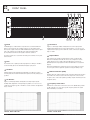
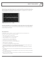
INSTALLATION AND OPERATION MANUAL
EQ302
GRAPHIC EQUALISER
IMPORTANT SAFETY INFORMATION
PRÉCAUTIONS DURANT UTILISATION
1. Read these instructions.
1. Lisez ces instructions.
2. Keep these instructions.
2. Tenez ces instructions.
3. Heed all warnings.
3. Notez tous les avertissements.
4. Follow all instructions.
4. Suivez toutes les avertissements.
5. Do not use this apparatus near water.
5. N’utilisez pas ce produit près de l’eau (la piscine, la plage, le lac, etc.).
6. Clean only with dry cloth.
6. Nettoyez seulement avec une étoffe sèche.
7. Do not block any ventilation openings. Install in accordance with the
manufacturer’s instructions.
7. Ne bloquez aucuns troux de ventilation. Installez en accord avec
les instructions du manufacturier.
8. Do not install near any heat sources such as radiators, heat registers,
stoves, or other apparatus (including amplifiers) that produce heat.
8. N’installez près aucunes sources de chaleur comme radiateurs, registres
de chaleur, fours ou les autres équipements (y compris amplificateurs)
qui produisent la chaleur.
9. Do not defeat the safety purpose of the polarised or grounding-type plug.
A polarised plug has two blades with one wider than the other.
A grounding type plug has two blades and a third grounding prong.
The wide blade or the third prong are provided for your safety.
10. Protect the power cord from being walked on or pinched particularly
at plugs and the point where they exit from the apparatus.
11. Only use attachments/accessories specified by the manufacturer.
12. Unplug this apparatus during lightning storms or when
unused for long periods of time.
13. Refer all servicing to qualified service personnel.
Servicing is required when the apparatus has been
damaged in any way, such as power-supply cord or plug
is damaged, liquid has been spilled or objects have fallen
into the apparatus, the apparatus has been exposed to
rain or moisture, does not operate normally, or has been
dropped.
14. This appliance should not be exposed to dripping or splashing water.
Never place objects filled with liquid such as vases on the apparatus.
15. Always ensure that the mains outlet is easily accessible for quick
disconnection.
16. In order to disconnect the apparatus from mains power completely,
the appliance plug should be removed from the mains wall socket.
17. WARNING: To reduce the risk of fire or electric shock, do not expose
this apparatus to rain or moisture.
18. An appliance with a protective earth terminal should be connected to
a mains outlet with a protective earth connection.
9. Ne défaites pas le but de sécurité de la fiche polarisée ou base-type.
Une fiche polarisée a deux tranchants avec un plus large que l’autre.
Une fiche de base type a deux a deux tranchants et une troisième
pointe de base, le tranchant large ou la troisième pointe est fourni
pour votre sécurité.
10. Protegez le cordon de secteur contre être marchée dessus ou pincez
en particulier aux fiches, aux douilles de convenance, et au point où ils
sortent de l’appareil.
11. Seulement utilisez attachements/accessoires spécifiés par le
manufacturier.
12. Arrachez la fiche du dispositif durant éclair et orage ou quand pas utilisé
pour longues périodes de temps.
13. Référez au personnel qualifié de service pour toutes
réparations. La réparation est donnée quand le système
a été endommagé à n’importe façon, par exemple un fil
ou une fiche endommagé(e) de la source
d’alimentation. Avoir été exposé à pluie ou humidité,
n’opère pas normalement, ou avoir été tombé.
14. L’appareil ne doit pas être exposé aux écoulements ou aux éclaboussures
et aucun objet ne contenant de liquide, tel qu’un vase, ne doit être placé
sur l’objet.
15. Branchez l’appareil à une source appropriée et faire que la prise à
débrancher soit facilement accessible.
16. La prise du secteur ne doit pas être obstruée ou doit être facilement
accessible pendant son utilisation. Pour être complètement déconnecté
de l’alimentation d’entrée, la prise doit être débranchée du secteur.
17. AVERTISSEMENT: Pour éviter le risque d’incendie ou de chocs électriques,
ne pas exposer cet appareil à la pluie ou à l’humidité.
18. Un appareil avec la borne de terre de protection doit être connecté au
secteur avec la connexiion de terre de protection.
INTRODUCTION AND CONTENTS
EQ302
INTRODUCTION3
The Australian Monitor EQ302 is a dual 30 band, 1/3 octave, constant
Q graphic equaliser with excellent performance and functionality
and is suitable for both installation and PA use. The equaliser has a
comprehensive set of features including 45 mm faders with +/- 15
dB of adjustment and offers balanced XLR, 6.35 mm TRS and Phoenix
connectors on both the input and output to provide ease of installation.
FEATURES4
FRONT PANEL
6
The EQ302’s Constant Q design means that there is minimum
interaction between filters, thus providing an improved clarity and
intelligibility of sound and more accurate adjustment over the 1/3
octave frequency bandwidth of each of its 30 ISO centred filters.
REAR PANEL
7
UNPACKING5
MOUNTING8
The high pass and low pass contour filters provide the added advantage
of being able to fine tune your sound to suite your required ambiance
without interfering with the previously equalised room settings. A high
pass filter allows for the removal of subsonic frequencies that may
cause damage to speaker systems.
ABOUT EQUALISERS
9
SPECIFICATIONS10
NOTES11
The Australian Monitor EQ302 has features usually associated with
equalisers many times the price and represents excellent value for
money for both permanent installations and operators alike.
Revision 1.0 October 2012
WARNING!
TO PREVENT FIRE OR SHOCK HAZARD, DO NOT USE THE PLUG WITH
AN EXTENSION CORD, RECEPTACLE OR OTHER OUTLET UNLESS THE BLADES
CAN BE FULLY INSERTED TO PREVENT BLADE EXPOSURE.
TO REDUCE THE RISK OF FIRE OR ELECTRIC SHOCK, DO NOT EXPOSE
THIS APPLIANCE TO RAIN OR MOISTURE.
TO PREVENT ELECTRICAL SHOCK, MATCH WIDE BLADE PLUG TO WIDE SLOT, FULLY INSERT.
CAUTION
RISK OF ELECTRIC SHOCK
DO NOT OPEN
The lightning flash with arrowhead symbol,
within an equilateral triangle, is intended
to alert the user to the presence of
uninsulated “dangerous voltage” within
the product’s enclosure that may be of
sufficient magnitude to constitute a risk
of electric shock to persons.
WARNING: TO REDUCE THE RISK OF ELECTRIC
SHOCK, DO NOT REMOVE COVER (OR BACK).
NO USER SERVICEABLE PARTS INSIDE. REFER
SERVICING TO QUALIFIED SERVICE PERSONNEL.
ADVERTISSMENT: POUR ÈVITER LE RISQUE
D’INCENDIE OU DE CHOCS ÈLECTRIQUES,
NE PAS EXPOSER CET APPARIEL À LA PLUIE
OU À L’HUMIDITÈ.
The exclamation point within an equilateral
triangle is intended to alert the user to
the presence of important operating and
maintenance (servicing) instructions in the
literature accompanying the appliance.
Rating plate and caution marking are marked on the back enclosure of the apparatus
EQ302 INSTALLATION AND OPERATION MANUAL
PAGE 3
FEATURES
The Australian Monitor EQ302 is a dual 30 band, 1/3 octave, constant Q graphic equaliser suitable for both permanent
installation and PA use. The equaliser is housed in a 19” 3 RU rack mount format.
Features include;
• Dual channel graphic equaliser providing +/- 15 dB cut / boost on each of the 30 ISO frequency bands.
• Centre detent bypass on 45 mm faders. When any fader is in its centre detent position, the filter is automatically
bypassed.
• High pass filter, frequency adjustable from OUT (flat) up to 250 Hz.
• LF Contour smooth shelving filter, +/- 6 dB of gain at 50 Hz
• HF Contour smooth shelving filter, +/- 6 dB of gain at 14 kHz
• GAIN control for overall unity adjustment. Variable from - infinity to +10 dB
• Triple-point LED clip detector that indicates when the internal signal is clipping at either the EQ filter, HF/LF contour or
gain sections of the equaliser.
• Precise LED metering indication. When the EQ switch is out, the LED meter indicates the input signal level.
When EQ switch is in, the LED meter indicates output signal level.
• Relay bypass. When the EQ is turned off or the power fails, an internal relay switches the input signal directly
to the output of the equaliser thus effectively bypassing the unit and maintaining a signal pathway.
• The bypass relay also provides a delay on power up to prevent audio clicks and thumps being generated by the
unit during boot up.
• Standard 3 RU 19” frame.
• Multiple balanced interface connectors. XLR, 6.35 mm jack (TRS) or Phoenix pluggable screw terminals are provided
at both the input and output terminals.
PAGE 4
EQ302 INSTALLATION AND OPERATION MANUAL
UNPACKING
Before using the product, please read this manual carefully and operate only in the manner described. If you have any
questions, please ask your local dealer or visit the Australian Monitor website www.australianmonitor.com for assistance.
Whilst unpacking the equaliser from its cardboard container, please check and ensure that no damage has occurred in
transit. Any damage to the goods must be immediately notified to the supplier. Retain any packaging until such time that you
are happy to take ownership of the goods. Please consider disposing of packaging in a suitably environmentally
friendly manner.
Contents
1 x EQ302, Dual 30 Band Graphic Equaliser
1 x User Manual
1 x IEC Mains Power Cable
4 x 3 way Phoenix connectors
Power Requirements
Before powering the equaliser, ensure that your mains power voltage is the same as the back panel voltage selections
switch indicates before connecting to the mains power outlet.
The switch allows you to select either 230 or 115 VAC mains supply at either 50 or 60 Hz.
This unit must always be connected to a suitable mains earthed outlet. It is recommended that any rack framework
used to mount the equaliser be also earthed to the same grounding circuit.
Always ensure that the equaliser’s power switch is off and that the power lead is disconnected from the mains power
supply prior to altering the voltage selection switch.
Before using the equaliser, please confirm the socket and the power cable are in good condition before connecting.
Always ensure that an appropriate fuse is used. The EQ302 is supplied with a T500mA M205 fuse which is suitable
for both mains voltages.
EQ302 INSTALLATION AND OPERATION MANUAL
PAGE 5
FRONT PANEL
6
8
1 EQ In
Individual bypass / enable buttons are provided for each channel. When the
button is deselected (out), the equaliser is bypassed, connecting the input
directly to the output of the device. With the EQ In button depressed, the signal
path of the equaliser is inserted between the input and output. A LED,
(A or B) indicates that the relevant equaliser channel is activated.
The bypass feature also occurs when the mains power is turned off or if power
fails to the unit.
2 Gain
Each channel of the equaliser provides input gain from - infinity to +10 dB to
ensure that unity gain can be maintained throughout your system.
3
2
5 4
7 1 3
2
4 5
4 LF Contour
Applies a continuously variable shelving filter to the low frequency band
allowing subtle adjustment of the low frequency balance of a room once it is
equalised. At a frequency point of 50 Hz the contour control has an adjustment
range of ±6 dB.
6 Output Meter:
Each channel of the equaliser is fitted with an accurate 8 segment LED,
RMS meter indicating level in dBu. The meters are configured to read the
output signal level of the equaliser when the EQ In button is depressed
(illuminated) and the input signal level when the EQ In button is out (channel
bypass).
Apart from identifying that a signal is present, the meter allows the operator
to use the gain control to adjust the equaliser for unity gain during set up.
3 HP Filter
Variable high pass filter adjustable from OUT (flat) up to 250 Hz to assist in
removing subsonic and other harmful lower frequencies that may damage your
speakers.
5 HF Contour
Applies a continuously variable shelving filter to the high frequency band
allowing subtle adjustment of the high frequency balance of a room once it is
equalised. At a frequency point of 14 kHz the contour control has an adjustment
range of ±6 dB.
contour boost HF & LF
PAGE 6
7 Overload indicator (CLIP)
Identifies when the equaliser signal is being overloaded. This indicator provides
an alert when an overload occurs in either the output of the contour section,
the gain section, or the actual equaliser, providing complete monitoring of levels
through the device.
8 Frequency band faders
With 45 mm of travel and a centre detent, each of the 30 ISO faders provides
15 dB of either boost or cut to the respective frequency band of the signal
whilst maintaining a constant Q.
contour cut HF & LF
EQ302 INSTALLATION AND OPERATION MANUAL
REAR PANEL
1
2
6
5
4
3
1 IEC Mains power socket and fuse.
2 Voltage Select
Voltage selection switch set at either 115 V or 230 V. Please ensure that your
local voltage has been selected before applying power to the unit. Refer to
Power Requirements section.
3 Input Channel A
A high impedance (10 kΩ) input is provided via either, XLR, 6.35 mm TRS
jack or Phoenix screw terminals. All the inputs are electronically balanced and
parallel connected.
4 Output Channel A
A low impedance output is provided via either, XLR, 6.35 mm TRS jack and
Phoenix screw terminals. All the outputs are electronically balanced and parallel
connected.
5 Input Channel B
A high impedance (10 kΩ) input is provided via either, XLR, 6.35 mm TRS
jack or Phoenix screw terminals. All the inputs are electronically balanced and
parallel connected.
6 Output Channel B
A low impedance output is provided via either, XLR, 6.35 mm TRS jack and
Phoenix screw terminals. All the outputs are electronically balanced and parallel
connected.
EQ302 INSTALLATION AND OPERATION MANUAL
PAGE 7
MOUNTING
The EQ302 is a 19” rack mounted unit and requires 3 RU (134 mm) of rack space. The equaliser is 180 mm deep and
consideration should be given to rear support, particularly if the unit is to be installed into a travelling road case were vibration
may be an issue. Whilst the equaliser does not radiate significant heat, care should be taken not to locate the unit directly onto
other heat producing equipment such as amplifiers. Always leave at least 1 RU between the equaliser and other equipment when
mounted in a rack.
The equaliser should not be used in temperatures above 45° C (113° F) or in proximity with high RF and / or electromagnetic
interference.
The EQ302 is earthed through both the three pin IEC mains socket and the chassis of the unit itself. It is good practice and highly
recommended that any rack framework used to mount the equaliser be also grounded to the same earth circuit as the mains
outlet.
Connections
To assist in easy installation, the EQ302 provides electronically balanced 10 kΩ balanced inputs and floating outputs providing full
headroom into loads above 600 Ω. These inputs and outputs are provided on three different connector types for each channel.
Each of the three connector types is wired in parallel:
1. 3-pin XLR connectors
2. Stereo 6.35 mm TRS jack sockets
3. Phoenix 5.08 mm pitch removable terminal blocks.
The XLR and 6.35 mm Jack pin assignments comply with professional audio wiring standards;
XLR Assignments
6.35 mm Assignments
PinSignal
Pin
1
Signal Ground
Sleeve Signal Ground
2
Hot (+) / In phase
Ring Cold (-) / Anti-phase
3
Cold (–) / Anti-phase
Tip Hot (+) / In Phase
Signal
Phoenix connectors are as per the rear connector label shown below (S = Signal Ground). The equaliser comes with 4 x 3 way
Phoenix plugs for ease of installation. Spare Phoenix terminals can be ordered from Hills SVL (code PC-508-3).
Phoenix assignments showing Input and Output B
S +
–
Output B
PAGE 8
S +
–
Input B
EQ302 INSTALLATION AND OPERATION MANUAL
ABOUT EQUALISERS
Graphic equalisers are used to modify the frequency contour of a sound system, primarily to correct problems posed by a room’s
acoustics. The graphic equaliser provides the ability to alter the frequency response of a sound system to ensure that the frequency
balance heard through the system loudspeakers better matches the original source. A well balanced room is essential to avoid
feedback and distortion and to provide clarity of the audio source material.
EQ302 adjustment curve +/- 15 dB
The Australian Monitor EQ302 is a 1/3 octave equaliser which means that the centre frequency of each of its filters are placed one
third of an octave apart (three filters per octave). The equaliser is a constant Q equaliser which means that each filter maintains a
consistent width and curve shape irrespective of the fader settings and therefore allows for more accurate equalisations without
interaction with adjacent frequency bands.
Set Up & Operation
The EQ302 graphic equaliser is designed to accept a line level signal from a mixer or professional audio processor.
The following is a quick set up guide for the equaliser (per channel);
1. Make sure that your audio source signal is muted.
2. Set the equaliser GAIN control to the centre detent, 0 dB position.
3. Ensure the EQ In button is in the “out” or bypass position.
4. Set all fader controls to the centre detent, 0 dB position.
5. Turn the HP filter control anticlockwise to the OUT position.
6. Set the HF and LF Contour controls to the centre detent, 0 dB position.
7. Apply audio signal to the equaliser input.
8. Press the EQ In button (LED will illuminate) to disengage the bypass.
9. If the CLIP (overload) LED illuminates, release the EQ In button and read the input signal level. If possible, adjust the source
audio signal so that the input level at the equaliser reads 0 dBu using the input meter.
10.With the EQ In button engaged again, equalise your audio system as desired using the equaliser faders for each frequency
band.
11.The adjustable HP Filter may be used to assist in removing unwanted subsonic and low frequency problems that may cause
speaker damage.
12.If the overall musical tonality of the room requires balancing, the contour controls can be used to ‘tweak’ the sound in both the
lower and upper frequency ranges.
13.Once the room is equalised, the GAIN control can be adjusted to read 0 dB on the output meter thus providing unity gain and
maximum headroom across the equaliser.
EQ302 INSTALLATION AND OPERATION MANUAL
PAGE 9
SPECIFICATIONS
Model description
EQ302 30 band constant Q dual channel graphic equaliser
Input impedance
10 kΩ balanced
Input headroom
8.5 V / +20 dBu
Frequency response (+/-1 dB)
5 Hz – 45 kHz
Distortion (20 Hz - 20 kHz, 0 dBu)
< 0.008% THD
Max Output Level
9.5 V / +21.7 dBu
S/N Ratio
> 92 dB
Dynamic range
> 110 dB
Cross talk @1 kHz
> 85 dB
Frequency bands (Q of 4)
+/-15 dB on ISO centre frequencies
HP filter control
(OUT) flat to 250 Hz, 12 dB / octave
LF contour @ 50 Hz
+/-6 dB / octave
HF contour @ 14 kHz
+/-6 dB / octave
Connectors (inputs & outputs)
XLR, 6.35 mm TRS, Phoenix 5.08 pitch
AC Power
115 / 230V, 50 / 60 Hz, 30 VA
Dimensions (W x D x H) 483 x 180 x 134 mm
(19” x 7” x 5.25”)
Net Weight
3 kg
(6.6 lbs)
Shipping Dimensions (W x D x H)
515 x 275 x 175 mm
(20.3” x 10.8” x 6.9”)
Shipping Weight
4.5 kg
(9.9 lbs)
ACCESSORIES (SUPPLIED)
Power cable (IEC)
1 Pcs
Manual
1 Pcs
PAGE 10
EQ302 INSTALLATION AND OPERATION MANUAL
NOTES
EQ302 INSTALLATION AND OPERATION MANUAL
PAGE 11
ENGINEERED BY AUSTRALIAN MONITOR
Address: 1 Clyde Street, Silverwater, Sydney NSW 2128 Australia. Private Bag 149, Silverwater NSW 1811 ACN 007 573 417
Website: www.australianmonitor.com.au International enquiries email: [email protected]
DISTRIBUTED IN AUSTRALIA AND NEW ZEALAND BY HILLS SVL www.hillssvl.com.au
NSW P: 02 9647 1411
E: [email protected]
QLD
ACT
P: 07 3852 1312
P: 02 6260 4544
E: [email protected] E: [email protected]
WA
P: 08 9204 0200
E: [email protected]
VIC
P: 03 9890 7477
E: [email protected]
SA
NZ
P: 08 8408 8300
P: 09 415 9426
E: [email protected] E: [email protected]