1
Assembly Instructions
Assembly Instructions
For Quick and Easy Assembly - First Read Entire Procedure
Then Follow Carefully The Step by Step Instructions
Tools you will need:
1.
Medium Sized Flathead Screwdriver, Pliers
and 7/16” & 3/8” wrenches
Parts you will use:
Parts for Models: 220
Parts for Models:120
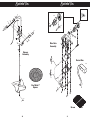
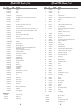
• (6)
Bolt - Hopper to Frame & Control
Tube to Hopper, 1/4-20 x 2"
Bolt - Control Brace to Hopper 1/420 x 3/4"
• (2)
Bolt - Deflector Shield to Frame 1/4
-20 x 13/4"
Bolt - Control Brace to Control Tube
& Levers to Control Tube 1/4-20 x
1 1/2"
• (1)
Bolt - Control Brace to Hopper 1/420 x 3/4"
• (3)
Bolt - On/Off Levers to Control Tube
& Brace to Control Tube 1/4-20 x 1
1/2"
• (1)
Lever Control Tube Brace
• (1)
• (3)
• (2)
Bolt - Lever Control Tube to Hopper
• (6)
Lock Nut
• (12)
Lock Nut
• (3)
Nylon Washer
• (1)
Lever Control Brace
• (1)
Plastic End Cap / Control Tube End
• (1)
Spinner Clip
• (1)
Spinner Shaft
• (1)
Hex Key for Spinner Shaft Coupler
• (1)
Spinner / Grey Plastic
• (2)
Hopper Bottom Bearing "for
Replacement"
• (1)
Mulch Spinner
• (1)
Hex Key for Spinner Shaft Coupler
• (2)
Hopper Bottom Bearing "for
Replacement"
• (9)
Nylon Washer
• (1)
Plastic End Cap / Control Tube
• (1)
Small Parts Bag with Agitator & Felt
Washer for use with grass Seed
• (2)
Set Screw 1/4-20 x 3/8" Allen for
Spinner Shaft Coupler
2
• (2)
Plastic End Cap / Frame
• (1)
Coupler for New Motor Shaft
2.
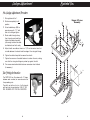
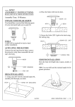
Insert Bump Bar
(1) into Frame (2),
but do not bolt
together at this
time.
* For model 120, skip
to step 4
Place Hopper
Assembly onto
Frame (2). Note:
The Rate Gate
Control Lever (4)
& the Accuway®
Control Lever (5)
go under the
frame cross
brace.
3