1
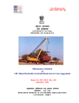
ISO 9001 : 2008
Specification No:
MP.0.08.00.62
Revision No: 00
Date Issued:26/03/2015
Specification Title: SAFE LOAD INDICATOR SYSTEM (SLI) ALONGWITH EVENT RECORDER
(For official use only)
(dsoy ljdkjh iz;ksx gsrq)
Hkkjr ljdkj
jsy ea=ky;
GOVERNMENT OF INDIA
MINISTRY OF RAILWAYS
SPECIFICATION
FOR
PROCUREMENT
OF
SAFE LOAD INDICATOR SYSTEM (SLI)
ALONGWITH EVENT RECORDER
FOR
140T DIESEL HYDRAULIC BREAKDOWN CRANES
(1676 mm Gauge)
MP – 0.08.00.62 (Rev. – 00),
March-2015
tkjh drkZ
Issued by
vuqla/kku vfHkdYi ,oa ekud laxBu]
Ekkud uxj] y[kuÅ - 226 011
RESEARCH DESIGNS AND STANDARDS ORGANISATION
MANAK NAGAR, LUCKNOW – 226011
DISCLAIMER
© RDSO 2014
ISO 9001 : 2008
Specification No:
MP.0.08.00.62
Revision No: 00
Date Issued: 26/03/2015
Specification Title: SAFE LOAD INDICATOR (SLI) ALONGWITH EVENT RECORDER
This specification is based on the studies and trials conducted by RDSO.
Although every care is taken in specifying details adequately and unambiguously,
RDSO shall not liable for any kind of damages / losses incurred by any and all
due to errors or omissions in this document. When using the information
described herein, the user is ultimately responsible for their own actions, as well
as the actions of subordinates and assistants, and the consequences arising
there from.
This document may mention numerous commercial and proprietary trade names,
registered trademarks and the like (not necessarily marked as such), patents,
production and manufacturing procedures, registered designs, and designations.
RDSO wishes to point out very clearly that the present legal situation in respect of
these names or designations or trademarks must be carefully examined before
making any commercial use of the same.
Names of industrially produced apparatus and equipment may be included to a
necessarily restricted extent only and any exclusion of products not mentioned in
this document does not imply that any such exclusion has been based on quality
criteria or any other qualifying consideration.
COPYRIGHT
RDSO has the copyright of all its publications. No part of these publications may
be reproduced in any form without the prior permission of RDSO. Enquires
relating to the copyright should be addressed to Executive Director
(Administration), RDSO.
ADDRESS FOR COMMUNICATION
Government of India - Ministry of Railways,
Research Designs & Standards Organization
Manak Nagar
Lucknow
Uttar Pradesh
India
Pin: 226 011
Fax:
+91 (522) 2458500
Phone: +91 (522) 2451200 (PBX)
+91 (522) 2450115 (DID)
Website: www.rdso.indianrailways.gov.in
© RDSO 2014
1
ISO 9001 : 2008
Specification No:
MP.0.08.00.62
Revision No: 00
Date Issued: 26/03/2015
Specification Title: SAFE LOAD INDICATOR (SLI) ALONGWITH EVENT RECORDER
1.
INTRODUCTION
1.1
The 140 tonne capacity Diesel Hydraulic break down Cranes are rail mounted
cranes and are being used for the purpose of tackling heavy loads and clearing
the tracks at the accident sites.
1.2
These cranes shall be provided with microprocessor/microcontroller controlled
safety system for operation while working on the accident sites.
1.3
Indian Railways want to upgrade the above system by including some
additional features.
2.0
2.1
GENERAL
This specification covers the requirement of design, development, manufacture,
supply, testing and commissioning into service of complete upgraded
microprocessor/microcontroller controlled safety system (including individual
parts) herein called as upgraded Safe Load Indicator System (SLI) alongwith
event recorder as a whole or in part for 140t breakdown cranes. The upgraded
system shall be compatible to the existing system fitted on the crane functionally
as well as physically.
2.2
The system shall have a “Self-testing feature” upon power turn-on and
continue to test itself repeatedly and unobtrusively during normal operation
and warn the user in advance during the case of malfunction. Further, in case
of malfunction, the facility of “Error code display” display of crane functional
characteristics / faults” with adequate information on service manual to trace
out a fault of the sensor, Printed circuit board (PCB) and further fault in that
unit shall also to be provided. The upgraded system shall also be equipped
with data logging for at least four days (96 hours) one year.
2.3
The system shall be capable of continuous operation during varying
atmospheric and climatic conditions occurring throughout the year to which a
crane is exposed normally in service. The range of climatic conditions is:(i). Ambient temperature
:
:
:
(ii). Altitude
(iii). Relative Humidity
(iv). Dusty and corrosive atmosphere with
dust content in air particle up to
:
(v). Heavy rainfall with thunderstorms
-10°C to 70°C 60°C
Mean Sea level to 1850 m.
40 % to 100 %
1.6 gm/m³
The tenderer shall provide the Microprocessor/microcontroller safety systems in
accordance with the best current international practices prevalent.
2.4
To facilitate examination of the tender offer, the tenderer is required to offer
comments clause by clause of this specification either indicating compliance or
otherwise against each clause and sub clause of the tender document. The
tenderer shall strictly adhere to the conditions of the specification. However, in
the event of tenderer being unable to conform to any clause of this specification,
© RDSO 2014
2
ISO 9001 : 2008
Specification No:
MP.0.08.00.62
Revision No: 00
Date Issued: 26/03/2015
Specification Title: SAFE LOAD INDICATOR (SLI) ALONGWITH EVENT RECORDER
it shall be stated specifically what variation there from is desired by the tenderer.
Deviation from the specification, if any, intended to improve the performance
and reliability of the Microprocessor/microcontroller controlled safety systems
can be considered. All such proposals shall, however, be accompanied with
complete technical details and justification for the proposed deviation.
For any deviation (s), the tenderer shall enclose a separate clause wise
statement along with the offer, indicating the deviation (s) and justification for
each deviation sought. In case there are no deviations a “Nil Deviation”
statement shall have to be furnished by the tenderer.
2.5
In case tenderer needs clarification on any clause of the specification or
regarding exhibited drawings, the tenderer / supplier shall submit each such item
to RDSO for immediate clarification.
3.0
3.1
SCOPE OF SUPPLY
Specification covers scope of supply of the following items in complete set of or
in part with accessories of the upgraded SLI similar to the
microprocessor/microcontroller controlled safety system already fitted on the
140t cranes:
a)
Central Microprocessor/microcontroller Unit
b)
Control Console cum Touch Screen Monitor
c)
Load Sensor
d)
Radius sensor Jib Angle Sensor / Radius sensor
e)
Jib Angle Sensor
f)
Super elevation sensor
g)
Gradient sensor
h)
Slewing Angle Sensor
i)
Counterweight sensor ( only for Gottwald old design crane)
j)
Real Time Event Recorder
k)
User friendly Display unit LED suitable for working in daylight. The
screen size of display shall be 10-15 inches.
l)
Prop (out-rigger) Level cum position sensor.
m)
Counterweight including tail radius sensor (only for Gottwald new design
crane)
n)
Load Charts for all duties
3.2
The tenderer shall be responsible for manufacture and supply of the
microprocessor/microcontrollerbased
Safe
load
indication
system.
Manufacturing of the system has to be done at the firm’s premises after which
the same be supplied at the nominated Workshop of Indian Railways.
3.3
The tenderer can also visit the Workshop before submitting offer to have
better appreciation of the crane and its maintenance and operational site
conditions. The Tenderer shall commission in all respects the Safe load
indicator system such that it matches with the requirements of the Load
charts of the said crane.
3.4
The tenderer shall be responsible for maintenance of the safe load indicator
system of the crane for a period of one year from the date o commissioning of
© RDSO 2014
3
ISO 9001 : 2008
Specification No:
MP.0.08.00.62
Revision No: 00
Date Issued: 26/03/2015
Specification Title: SAFE LOAD INDICATOR (SLI) ALONGWITH EVENT RECORDER
the safe load indicator system on the crane, and shall attend to ‘ scheduled
calls’ and ‘emergency calls’.
The tenderer shall be responsible for
maintenance of the crane SLI system till the end of the codal life of crane
from the date of commissioning of the Safe load indication system on the
crane and shall attend to ‘Scheduled calls’ and ‘Emergency calls’. The SLI
system manufacturer shall be responsible for re-engineering /re-designing of
any component of SLI system which is rendered obsolete so as to ensure that
the component is fit for purpose for proper functioning of the SLI system.
3.5
4.0
The tenderer should study the tender documents including general conditions
of contract, special conditions of contract, scope of work and technical
specifications to understand the complete work involved for proper execution
of work. In case the tenderer offers optional features in addition to the
minimum features as per specifications, the same should be separately
mentioned in the offer along with incremental cost, if any.
TECHNICAL REQUIREMENT
The system shall be developed for following requirements:
i)
ii)
iii)
iv)
Design technology = Microprocessor/microcontrollerbased
Accuracy = ± 2 % SWL
Supply Voltage= 24±4 V DC (fuse protected)
Display = Color, touch screen with backlight anti-reflective
Window, clear visibility even in day time
v) Control Panel = Sealed touch sensitive
vi) Display sealing = IP65
vii) Peripheral com port = RS232
viii)Preprogrammed Data = EPROM based Data
ix) Data Memory chip = EPROM for calibration data storage, data logging & load
charts.
x) Readings = IS system only would be acceptable.
xi) Password protection = to be compulsorily provided to prevent unauthorized
tampering of setting & calibration.
The Tenderer shall conduct retro-fitment which would include stripping of the
existing Safe load indicator system (along with harness and sensors) at the
nominated work sites and collect the same and handover to authorized Railway
representative. The work shall be conducted in such a manner that no damage
in any respect is caused to the crane. The contractor shall be responsible for
assembling the Safe load indication system including fitment on the crane and
wiring of the complete system in least possible time.
4.1
External audible alarm:
The display unit, at the driver’s console, shall house an integral audible alarm.
This alarm shall warn when the load on the crane exceeds the preset “approach
to SWL” warning threshold. The alarm shall become continuous once the load
exceeds the preset “overload” warning threshold. In addition, an external audible
alarm shall give a simultaneous “overload” warning. Also, external audible alarm
output for ‘cut’, ‘unsafe condition’ and ‘fault’ shall be provided. The safe load
indication system shall be compulsorily provided by the contractor with GPS
© RDSO 2014
4
ISO 9001 : 2008
Specification No:
MP.0.08.00.62
Revision No: 00
Date Issued: 26/03/2015
Specification Title: SAFE LOAD INDICATOR (SLI) ALONGWITH EVENT RECORDER
(Global Positioning System) based location detection and data downloading
facility with GSM based interface, to enable forwarding messages to a
registered mobile number (available with Railways). This shall be adopted on all
SLI systems and shall have adequate support from the OEM of SLI systems for
maintaining data for a year
4.2
General working of the crane alongwith functioning of existing SLI system is
briefed as follows:
4.2.1 The control system of the crane permits motion to continue within the safe limits
and cut off the motion when it tries to go beyond the permissible working zone.
The existing various working parameters and their limits within the working zone
have been defined in load charts given in Annexure 1-10 (enclosed).
In addition to the above, the tenderer shall also provide load charts for ± 45° & ±
60° slewing. For additional details regarding load charts of safe load indicator
can be obtained from CWM (Crane)/ Eastern Railway, Jamalpur Loco workshop
on old and new Gottwald design crane and CWM (Crane)/ Central Railway,
Parel Loco workshop on Cowans sheldom crane. For the performance of this
upgraded SLI, with this feature, shall be tested at Jamalpur Loco workshop and
Parel Loco workshop. The tenderer shall be responsible for programming of
upgraded SLI with this feature.
4.2.2 Safety Requirements:
The Safe load Indication system shall satisfy the following safety requirements:
• Reverse power polarity protection.
• Moisture resistance = 100 %.
• Open and short circuit sensor detection.
• Watchdog facility.
• Stability against temperature, humidity and vibration.
4.2.3 Hoisting of load through Auxiliary Hoist:
Hoisting motion shall get cut off when auxiliary hoist tries to lift a load more than
the permissible of the concerned load chart and permitted maximum load on the
auxiliary hook. Manufacturer shall provide improved design of draw wire
sensors, incorporating hysteresis compensation for accurate load indication
during hoisting / lowering operation.
4.2.4 Hoisting of load through Main Hoist:
Hoisting motion shall get cut off when main hoist tries to lift a load more than the
permissible of the concerned load chart and permitted maximum load on the
main hook. Manufacturer shall provide improved design of draw wire sensors,
incorporating hysteresis compensation for accurate load indication during
hoisting / lowering operation.
4.2.5 Derricking Motion
Raising or lowering of the crane jib is termed as “Derricking In” and
“Derricking Out” respectively. Changes in jib position changes the radius
© RDSO 2014
5
ISO 9001 : 2008
Specification No:
MP.0.08.00.62
Revision No: 00
Date Issued: 26/03/2015
Specification Title: SAFE LOAD INDICATOR (SLI) ALONGWITH EVENT RECORDER
mentioned in the load charts. Radius is defined as horizontal distance between
concerned hook (main / auxiliary as applicable) and centre of rotation of the
super - structure of the crane. It may be observed that other parameters
remaining same in the load chart, increase in radius reduces the lifting capacity.
The control system cuts off the derricking motion at extremes of working radii
range when the hoisted load tries to go beyond the permitted radius.
4.2.6 Slewing Motion
Rotation of super - structure is termed as “Slewing”. For various parameters as
per load chart slewing angle has been defined. It may be observed that other
parameters remaining same, for a fixed radius, hoisting capacity is more for
smaller slewing angle and less for slewing angle beyond certain value. Slewing
motion gets cut off when for a given parameter, super – structure tries to enter
the slewing angle not permitted as per load chart.
4.3
EXISTING FEATURES OF SLI
The existing SLI system fitted in Gottwald old design cranes gets sensing
signals through 4 nos. of sensing devices and 13 inputs which are fed by
switching through manual mode. Suitable modification shall be required in new
design crane also. Brief of sensing signals is given below:
4.3.1 Load Sensor
•
This sensor has been fitted on gantry rope / equalizing beam / near jib
head. It senses the load lifted by the main hook or auxiliary hook. Load
sensor consists of a load cell/shear pin on each side of the equalizing
beam, which senses the load and gives equivalent electrical signal to the
system.
•
The tenderer shall manufacture and commission Safe load indication
system for automatic duty selection containing subsystems. The Safe
Load Indication system of the crane shall permit the motion to continue
within the safe limits and cuts off the motion when it tries to go beyond
the permissible working zone. Load charts shall be fully protected and
non-editable.
4.3.2 Jib Angle cum Radius Sensor
The sensor senses the angle of inclination of the jib. Equivalent electrical signal
for the crane radius is given by this unit to the control system.
4.3.3 Slewing angle sensor
The sensor senses the angle by which super structure is slewed from the match
truck side in clockwise or anti-clockwise direction, the maximum being 360
degrees in either direction. Equivalent electrical signal for the slewing angle is
given through this sensor to the control system.
© RDSO 2014
6
ISO 9001 : 2008
Specification No:
MP.0.08.00.62
Revision No: 00
Date Issued: 26/03/2015
Specification Title: SAFE LOAD INDICATOR (SLI) ALONGWITH EVENT RECORDER
4.3.4 Counterweight sensor:
Each load chart is for a particular counter weight combination. Counter weight is
the balance weight that is hung with the rear of the super structure. Counter
weight remains hanging with the super structure and remains raised from the
top of the under carriage with the help of the two hydraulic cylinders. There are
following three combinations of counterweight indicated in respective load charts
appended as annexures for old design Gottwald cranes:
i)
43.2 Tonnes wt. or Heavy Duty Counter Weight.
ii)
29.2 Tonnes wt. or Standard Duty Counter Weight.
iii)
No weight or No Counter Weight.
Whereas, following three combinations of counterweight indicated in respective
load charts appended as annexures for new design Gottwald cranes:
i)
47 Tonnes wt. or
ii)
29.2 Tonnes wt. or Standard Duty Counter Weight.
iv)
No weight or No Counter Weight.
Combination of counter weight sensing is done through pressure switch which
sets the path for a particular circuit giving signal to the Control System and by a
manually operated switch for new crane.
4.4
NEW FEATURES IN SLI
4.4.1 Real Time Event Recorder
i) This shall GPRS based and data will be transferred directly to web and log all
the important events automatically with time and date stamp, when one lift is
executed i.e. if load is lifted above 25T (a defined limit load / programmed) over
main hook, it shall trigger to record load along with other crane parameters.
Data logger memory card of suitable capacity as agreed to between tenderer
and RDSO shall be provided for recording or data logging of all operations
including Input / Output fault detection, which can later be analysed for
maintenance purposes
ii) This shall work as a black box and will provide valuable information for analysis
of the users. Battery backup for data storage and on screen time & date wise
fault analysis shall also be available.
iii) The Time & Event Recorder unit shall continuously record the crane working
data. The time interval between the records shall be as short as one second.
The recorder shall decide the time interval automatically. The recording of this
data shall be loop (circular) type i.e the current data will over write the already
recorded data if the memory is full. An indication for memory full shall come on
the screen when only 10% reserve memory is left. The data downloaded from
the memory shall be transferred to a PC, lap top, palm top or any other futuristic
hand held terminal (HHT) equipped with evaluation software. The equipment
being a safety item shall be designed for high degree of reliability. A layout
properly showing the location of fitment this recorder, shall be approved by
RDSO.
© RDSO 2014
7
ISO 9001 : 2008
Specification No:
MP.0.08.00.62
Revision No: 00
Date Issued: 26/03/2015
Specification Title: SAFE LOAD INDICATOR (SLI) ALONGWITH EVENT RECORDER
iv) The electronic memory shall be accessible through USB interface (locked under
cover) to an IBM compatible PC/Lap top computer/ pen drive (Flash memory
storage device).
v) It shall be possible to sort out this data with suitable commands on the
computer. Alternatively, it shall directly web transfer the stored data to web and
be possible to download the data directly from a PC/laptop/pen drive (Flash
memory storage device) by connecting to the USB port on the ‘Event Recorder’..
vi) Printing of data of event memory, shall be in continuous printing format, instead
of screen-by-screen printing, to cut down printing time. The down loading of the
memory data should not affect other work like printing, processing of other work
etc.
vii) The printing/plotting of data shall be in detail, in digital or graphical format as
desired. The software shall also provide for printing of the data in in the following
selective format:
a. Only the page desired to be viewed.
b. Continuous print out of all the pages.
c. Between the desired times.
d. Data above or below a specified parameter.
e. Data of a particular event.
viii)Necessary software for data retrieval, analysis and printing, in the above
manner shall be developed and supplied by the manufacturer of the ‘Event
Recorder’. The software shall be menu-driven and shall not require knowledge
of programming and shall be suitable to be operated with minimum computer
lieteracy. The software shall have file management system for retaining the data
in the file name assigned by the operator. The file name of the downloaded file
should carry the crane no. and date of downloading. The file management
should also allow conversion of downloaded file to document file format
including MS Excel, MS Word etc. also and the data saved should be displayed
in tabular and graphical formats.
ix)
A “Memory Freeze” facility shall be provided to allow the crane to be moved
after an incident, without over writing the Event Recorder data, stored during last
24 hours and data stored capacity shall be one year and also Data stored shall
be password protected of crane working. The switch for freezing the data shall
be under a sealed glass cover on “Event Recorder units”. The glass shall be
broken when required, for operating the switch. A LED freeze
x) A warning display shall be provided on the Event Recorder module, which will
indicate any failure in the memory recording. The warning display should be
LED based.
xi) The tenderers are advised to study the space availability, location and other
requirements, before submitting the offer, in their own interest.
xii)
Time and Event Recorder shall have a self – diagnostic feature. In case of any
malfunction, the system must indicate the fault LED display.
© RDSO 2014
8
ISO 9001 : 2008
Specification No:
MP.0.08.00.62
Revision No: 00
Date Issued: 26/03/2015
Specification Title: SAFE LOAD INDICATOR (SLI) ALONGWITH EVENT RECORDER
4.4.2 User friendly display unit: User friendly LED display unit with 1.3 to 1.4
megapixel resolution shall be provided with TFT, color touch screen and actual
display area size of 8.3”x 6.3” and 10.4” or higher diagonal of elegant design
having surrounded with cover to protect direct sun light on the screen. The
display design shall be planned to display following parameter(s) effectively
using crane graphics, dials, bar graphs etc. with scrolling main and sub-menus /
selection bars over the color touch screen display:
- Actual & permitted load of main hook
- Actual & permitted load of Auxiliary hook
- Actual radius & jib angle
- Permitted Radius
- Actual slew angle position & zone indication.
-Duty selection configuration based on feedback from all essential sensors.
-Digital indication/ level of under carriage, Super elevation & Gradation.
- Safe Load Indication System overrides indication
- Error code indication Crane functional characteristics / faults indication.
- Counterweight selection indication
- Rail clamp selection indication on Free On Rail (FOR) & Propped condition
- Over hoist indication
The operator’s display must be user friendly to indicate warning signals as
follows:
(a) Approach: This indicates that the hook load has exceeded 95% of the rated
load. The internal audible alarm operates simultaneously with this lamp.
(b) Overload: This indicates that the hook load exceeded 105% of the rated
load. The internal alarm and external warning horn should simultaneously
operate
(c) Cut: This indicates that the hook load has exceeded 110% of the rated load.
Relay contacts should be available in the Central Processing Unit to cut
relevant crane motions when this occurs
(d) Fault: This indicate actual fault during the operation of Crane.
(e) Data EPROM failure
(f) Test: This indicates the self test of
Microprocessor/microcontroller/microcontroller
(g) Over hoist Check
(i) Slew position range
There shall be comprehensive on-screen fault indication and diagnosis alarm /
reporting with ‘on screen error code’ display, ‘On- screen’ page mode calibration
facility, Pop-up window selection , Pop-up window for indication and also
warning in case any of the above SLI parameters approach mishap conditions.
All digital displays shall be in 0.1 increments and there shall be Backlight display
for night vision. The system shall be provided with the features of displaying
data history over screen. The operator’s display shall be active despite the
system having been by-passed for some reason.
© RDSO 2014
9
ISO 9001 : 2008
Specification No:
MP.0.08.00.62
Revision No: 00
Date Issued: 26/03/2015
Specification Title: SAFE LOAD INDICATOR (SLI) ALONGWITH EVENT RECORDER
4.4.3 Prop (Out – Rigger) Position Sensor: Prop position sensor shall be provide to
ensure proper leveling & positioning of all 4 props of the crane while working at
site. Out – riggers/props are the flap type structure one each at the four corners
of the under – carriage. Depending on the working requirements outriggers are
used in three positions. This is accomplished through lateral hydraulic cylinders.
The three positions are indicated by the following conditions:
i)
ii)
ii)
iii)
Propping base of 6.0 m when the counterweight is completely extended.
Propping base of extension between 2.7 m or more but less than 6.0 m.
Propping base with intermediate propping positions i.e between 6.0m and
2.7m
Outrigger is not extended and wheels of the crane continue to rest on the
rails.
The control system/Limit Switches shall sense automatically any of the above
three prop positions of the out –rigger by electrical signal & any unevenness in
the prop levels arising at the time of working with loads and shall keep driver
informed about the level & position of the props.
4.4.4 Counter weight cum Tail Radius Sensor
Crane works in different working configurations as per the duty requirement at
the site. In Gottwald old design cranes, cwt. attached to the crane is
automatically sensed by SLI & the tail radius is fixed at 5.5m. However, in
Gottwald new design cranes, the same feature is not there on account of
different type of counterweight support arrangement and also variable tail radii of
5.5m & 6m respectively.
This feature shall ensure automatic selection of appropriate load chart after
sensing actual counterweight attached to the crane.
Control system shall sense counter weight / tail radius positions by electrical
signal by a manually operated switch.
4.4.5
Load Charts:
In addition to existing duties load chart shall also include
duties for ± 45° & ± 60° slewing so that only after crossing ± 60° slewing on
either side track CL the duty chart of ± 90° slewing configuration has to be
selected. This feature will provide more duties and flexibility in crane
operation. The existing SLI is working with load chart of Full prop and half
prop. The SLI systems for 140T cranes shall be provide with intermediate
propping positions system. This feature will provide more duties & flexibility in
crane operation.
4.4.6 Complete information of the load charts form the reference information for the
central unit of the computer. Sensing of parameters as explained above shall be
done continuously and the signals given to the central unit. Central unit shall
compare actual parameter with the reference and accordingly controls the crane
motion by cutting off power to electrically operated hydraulic valves (called
Solenoid Valve). Prior to cutting of the motion crane driver shall be warned
through audio cum visual signals.
© RDSO 2014
10
ISO 9001 : 2008
Specification No:
MP.0.08.00.62
Revision No: 00
Date Issued: 26/03/2015
Specification Title: SAFE LOAD INDICATOR (SLI) ALONGWITH EVENT RECORDER
4.4.7 There shall be a display unit in drivers cabin which shall display number of
parameters and give audio visual signals which are explained in clause 4.4.2.
4.4.8 The microprocessor consists of 5 numbers of printed circuit board which are
shown
in
the
manual
enclosed.
The
system
should
be
Microprocessor/microcontroller based & contractor should design system
incorporating characteristics accordingly as per details given below:
a) Power supply
b) Relay card.
c) Signal processing unit
d) Touch screen monitor display.
4.4.9 There shall be provision for digital display of error – code crane functional
characteristics / faults to identify and locate the fault in the system for
maintenance. In case of fault or any problem, provision for manual by – pass of
the system shall provide. Even after by – pass display unit shows the actual
parameters after sensing (excluding the defective area), only the motion cut –
off is by passed.
4.4.10 In addition to above display, display console shall have additional provision of
digital display of load reading. During simulation of load chart, load can be
checked in this load display and existing display console will be used for display
of slewing angle.
5.
6.
6.1
6.2
6.3
6.4
CONTRACTOR’S RESPONSIBILITY
The contractor shall be entirely responsible for execution of the contract strictly
in accordance with the terms & condition of this specification/ contract,
notwithstanding any approval, which the purchaser or the nominated Inspecting
Officer may have given:
a)
Of the detailed drawings prepared by the contractor.
b)
Of his sub-contractors for materials.
c)
Of other parts of the work involved by the contractor.
d)
Of the test carried out either by the contractor or by purchaser or the
nominated Inspecting Officer.
QUALITY ASSURANCE PLAN (QAP)
The tenderer shall provide satisfactory documents acceptable to the purchaser,
to the effect that manufacturer has adequate machinery & plant facilities and
follows a “Quality Assurance Plane”.
The contractor shall furnish details of his experience in the field of manufacture
and supply of Microprocessor/microcontroller controlled safety system. He shall
provide a list of suppliers to whom similar items have been supplied in the last
three years and have been used as on heavy duty crane (i.e. more than 120t)
anywhere in the world.
QAP shall include details of different tests/checks to be done during each stage.
In view of criticality of SLI systems in functioning of the 140T crane at accident
sites, a detailed Quality Assurance plan shall be adhered by the OEMs.
© RDSO 2014
11
ISO 9001 : 2008
Specification No:
MP.0.08.00.62
Revision No: 00
Date Issued: 26/03/2015
Specification Title: SAFE LOAD INDICATOR (SLI) ALONGWITH EVENT RECORDER
7
INSPECTION AND TESTING
7.1
Equipment as supplied in part or as a complete system is to be tested at firm’s
premises. The firm shall arrange setting up of simulated condition for inputs and
outputs by means of digital indicators and lamps as agreed and approved by the
purchaser.
7.2 All the load charts provided with operating manual shall have to be simulated and
jointly checked in the presence of RDSO, Jamalpur representatives and
inspector nominated by purchaser.
a) The firm shall confirm that the system complete or in part under supply
meets the functional requirements of the crane working, within the restricted
parameters as defined in load charts.
b) The firm shall also confirm that the PCB’s and Sensors input/output
response exactly tallies with that of original system as provided in the
cranes.
7.3
The contractor shall, at his own cost, carry out any modifications deemed
necessary as a result of simulation tests. The contractor shall also bear costs for
inspection as required by the purchaser or his authorized representative.
7.4
Display console having provision of all the displays as laid down in para 4.4.2
will be tested both at the firm’s premises and also on the crane.
7.5
All the sensors should be calibrated matching with digital values of different
parameters exhibited on LED touch screen.
8.0
COMMISSIONING AND PROVING TEST
8.1
After simulated test at firm’s premises are successfully over, testing of the
system complete or in part shall be jointly done by Firm, RDSO ,Jamalpur
representatives and inspector nominated by purchaser after fitting it in first two
working crane and testing the crane working under all the working conditions for
all prescribed duties.
9.0
TRAINING
9.1
Training of Indian Railway Engineers in the firm’s premises sheds/workshops. At
least two persons of shed holding the crane and one two from each Parel and
Jamalpur workshop for two days at least.
9.2
Practical Training of Indian Railway engineers and artisans at Parel and
Jamalpur workshops during change in the existing Safe Load Indicator with
upgraded Safe Load Indicator.
9.3
Training Programs: The contractor shall conduct the following training
programs
on operation, maintenance and troubleshooting of the safe load
indicator system at Crane depot/Workshop.
© RDSO 2014
12
ISO 9001 : 2008
Specification No:
MP.0.08.00.62
Revision No: 00
Date Issued: 26/03/2015
Specification Title: SAFE LOAD INDICATOR (SLI) ALONGWITH EVENT RECORDER
9.4
9.5
Appreciation and Orientation program for Managers/Engineers: One such
training program for one full day for 15-20 persons shall be conducted using
audio-visual aids with provision of training material in the form of soft copies,
hard copy documentation and stationary etc. to be made by the contractor.
Training Program for Crane In-charges and Crane Staff: One such training
program for two full days for 15-20 persons shall be conducted using audiovisual aids with provision of training material in the form of soft copies, hard
copy documentation and stationary etc. to be made by the contractor.
9.6
Refresher Program for Crane maintainers and operators:
The tenderer shall conduct training programs for two full days for 15-20 persons
using
audio-visual
aids.
The
tenderer
shall
provide
training
literature/documents/stationary etc. in soft & hard copy. The date and time of the
training programs shall be decided by Crane depot Incharge /Workshop. Indian
Railways shall provide conference room alongwith audio-visual aids like
multimedia projector board, free of cost for the training programs. The training
program shall also include site visit to the nearest Accident Relief Train depot
with a 140t crane. The tenderer shall arrange local transportation for trainees to
the nearest Accident Relief Train depot with a 140t crane from the venue where
the training program is being conducted.
10.0
SERVICE MANUAL AND SPARE PARTS CATALOGUE
10.1
Detailed operating manual, maintenance manual, schedule (time bound) and
modified circuit diagram shall be specially prepared, two copy each per set per
order of the same shall be supplied free of cost. The manual shall include all
information relevant to maintenance, servicing and spares provided by the
vendors/OEMs as part of their supply. All manuals shall additionally be provided
on DVD/Pen drive in editable format. Draft contents of the manuals shall be
submitted for approval of the RDSO. Two copy each of the detailed spare parts
catalogue listing all components manufactured or purchased (with source of
supply and budgetary price) shall also be supplied.
10.2
In addition, it is proposed to stock sufficient child components and spares to
meet the normal renewals and replacements on account of wear or occasional
failure. So, in this regard an itemwise list with quotations, drawing reference,
specification, source of supply, etc shall also be submitted.
10.3 The successful tenderer shall provide the complete drawings of all components
required for operation, repair & maintenance of the safe load indicator system in
electronic form (Auto CAD Mechanical RP6 or any other suitable graphics
software as decided by Deputy Chief Mechanical Engineer (Crane) of
Workshop or Assistant Works Manager (Crane) Workshop) along with one set of
hard readable copy in A4 size.
© RDSO 2014
13
ISO 9001 : 2008
Specification No:
MP.0.08.00.62
Revision No: 00
Date Issued: 26/03/2015
Specification Title: SAFE LOAD INDICATOR (SLI) ALONGWITH EVENT RECORDER
11.0
SERVICE ENGINEERING AND AFTER-SALES SERVICE
11.1
The tenderer shall provide at his own expense the services of competent
engineers during commissioning as well as warranty period of the equipment.
11.2
The tenderer shall clearly bring out the facilities available with him or his subcontractor for providing adequate after-sales service during warranty as well as
post warranty period. The tenderer shall indicate the service organization at
various places in India and the availability of trained staff, maintenance spares
etc. at these places
Codal Life and AMC/FSMA
12.
12.1
SLI systems shall be microprocessor/microcontroller controlled based units till
the residual life of the existing cranes. OEMs of SLI systems shall be replaced
cabling / wiring and connectors in Workshops during POH/MLR. The display unit
and sensors should be checked for it functional characteristics and replaced on
condition basis during POH/MLR.
12.2
The SLI systems should invariably be covered under AMC during service
between two POH in case expertise is not available with crane depot, or
under a formalized maintenance schedule arrangement in case expertise has
been developed within Railways.
12.3
Various aspects of AMC, including duration of the AMC, number of cranes and
types of SLI systems to be covered by a particular Railway under the AMC
shall be decided by each Railway for 140T cranes under its jurisdiction.
12.4
The AMC shall be conducted by the respective Original Equipment
Manufacturer (OEM) or their authorized agencies only. The child spares of the
parent assemblies shall be procured from the OEM or their authorized
agencies as prescribed by Board on similar lines to system on critical
assemblies of locomotives.
12.5
In case of PAT SLI systems wherein the OEM does not have a presence in
India since long, the existing system of AMC shall continue. Retro-fitment of
such obsolete systems by a technologically current SLI system is being
planned.
13.0
TOOLS
The tenderer shall supply one set of tools required for day to day maintenance
along with each complete system ordered.
14.0
TESTING KIT
The tenderer shall specify the testing equipments as may be required for
optimum and trouble free performance of the system.
© RDSO 2014
14
ISO 9001 : 2008
Specification No:
MP.0.08.00.62
Revision No: 00
Date Issued: 26/03/2015
Specification Title: SAFE LOAD INDICATOR (SLI) ALONGWITH EVENT RECORDER
15.0
PACKING
After satisfactory inspection and testing of the system or its part, it should be
suitably packed to avoid damage during transit.
*****************************
© RDSO 2014
15