1
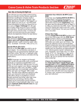
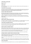
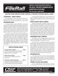
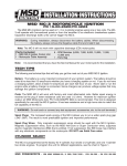
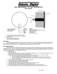
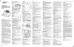
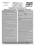
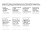
Installation Instructions for
HI-4N MOTORCYCLE IGNITION
For more information, see www.cranecams.com
CAUTION: READ INSTRUCTIONS CAREFULLY BEFORE STARTING INSTALLATION.
2.Refer to Figure 1. Remove ignition cover plate, gasket, and
INTRODUCTION
hardware (items 1-3). Save these items for later re-use.
The HI-4N ignition system is intended for use with Harley-Davidson® motorcycles. The HI-4N replaces the original equipment
(OE) electronic ignition system on 1978 and later models as well
as the points and mechanical advance on early models. Will not
work in 2000–2003 Sportster®.
3.Note location of breaker plate. There is a V notch in the breaker
plate used for alignment. When you install the HI-4N, align the
V notch in the same location. This should set the timing close
enough to start the engine. Remove and save the two standoffs
and washers (items 4-5). Remove the breaker plate assembly,
wiring, cam, and advance assembly (items 6–10).
WARNING: 1996 and later models have a vehicle tilt sensor that
shuts off the ignition if the motorcycle rolls on its side. This
feature is disabled when the HI-4N ignition is installed.
REMOVAL OF OE ELECTRONIC IGNITION
SYSTEM—1978 AND 1979 MODELS
The HI-4N features state-of-the-art technology that allows adjustable
advance and rev limit. A timing LED indicates static timing (top dead
center) and gives diagnostic information. Two starting modes are
provided: electric start and kick start. A tach output gives accurate
tach readings even at the rev limit.
1.Turn ignition switch off and disconnect battery ground cable.
2.Refer to Figure 2. Disconnect wires going from ignition module
(item 3) to coil (14).
3.Remove ignition cover plate and hardware (items 1 and 2). Save
these items for later re-use. Remove ignition module (3).
ADDITIONAL REQUIRED PARTS
FX series Big Twin® and XL series Sportster® models prior to
1984, FL series Big Twin® models prior to 1985, and all models
with OE points will require OE timing rotor P/N 32402-83. This
part is not included with the HI-4N installation kit and can be
purchased separately, Crane Cams Part Number 8-1150.
4.Note location of timer plate (10). There is a V notch in the timer
plate used for alignment. When you install the HI-4N, align the
V notch in the same location. This should set the timing close
enough to start the engine. Remove and save the two standoffs
and washers (items 4-5). Remove the sensor, shield, timer plate,
trigger rotor, and advance assembly (items 6-12).
COIL AND SPARK PLUG CABLE
CONSIDERATIONS
REMOVAL OF OE ELECTRONIC IGNITION
SYSTEM—1980 AND LATER MODELS
We recommend replacing the OE coil. Coils used with the HI-4N
must have at least 2 ohms primary resistance. Coils with 4 ohms
or higher may be used, but may not produce optimum output. We
recommend the following coils for single and dual-plug applications:
1.Turn ignition switch off and disconnect battery ground cable.
2.Refer to Figure 3. Remove OE ignition module and wire harness
(items 1-4). You will disconnect two wires at the coil, wire going to
the VOES (Vacuum Operated Electrical Switch), ground wire at
the module, and the 3 pin plug (20) that connects to the sensor
plate. Refer to shop manual for locations.
HI-4N Ignition With Single Plug Heads. Use Crane Cams P/N
8-3005 coil, which will fit in the stock mounting location on most H-D®
motorcycles. You can also use two dual spark tower coils and ground
one of the towers on each coil to the engine case or frame. You will
have to fabricate a bracket to mount the second coil.
3.Remove ignition cover plates and gasket (items 5- 9). This will
require drilling out two rivets. The rivets will later be replaced
with two supplied self threading screws.
HI-4N Ignition With Dual Plug Heads. Use two Crane 8-3006 coils.
You will have to fabricate a bracket to mount the second coil.
4.In order to remove the sensor plate cable, the cable plug (20)
must be removed first. Use needle nose pliers to pull the terminals out of the plug. Then pull the cable through the exit hole at
the bottom of the timing cover.
Crane FireWire spiral core wires are recommended for maximum
performance. Do not use solid copper spark plug cables; they may
cause interference with your ignition system and accessories.
5.Note location of sensor plate (11). There is a V notch in the sensor
plate used for alignment. When you install the HI-4N, you should
align the V notch in the same location. This should set the timing
close enough to start the engine. Remove and save the two standoffs and washers (10). Remove the sensor plate (item 11).
REMOVAL OF POINTS IGNITION —
EARLY MODELS PRIOR TO 1978
1.Turn ignition switch off and disconnect battery ground cable.
Disconnect wire going from breaker points to Coil– (negative)
terminal.
Daytona Beach, FL 32117 | www.cranecams.com | Phone: 866-388-5120 | Fax: 386-236-9983
6/12
1
9000-6100
Figure 1. Harley-Davidson® OE Points System
11
10
8
9
6
7
5
4
3
2
1
1. Circuit Breaker Cover Screws (2)
2. Circuit Breaker Cover
3. Circuit Breaker Cover Gasket
7. Circuit Breaker Cam Bolt
8. Breaker Plate Assembly
9. Breaker Cam
10. Advance Assembly
4. Breaker Plate Screws (2)
5. Breaker Plate Screw Lockwashers
& Washers (2 each)
6. Retainer (1971 to early 1972)
11. Gear Case Cover
Figure 2. Harley-Davidson® 1978-79 OE Electronic System
17
1. Cover Screws (2)
10. Timer Plate
2. Ignition Timer Cover
11. Trigger Rotor
3. Ignition Module
4. Timer Plate Screws (2)
12. Advance Assembly
13. Gear Case Cover
5. Washers (2)
6. Screws & Washers (2 each)
14. Ignition Coil
15. Spark Plug Wires (2)
7. Shield
8. Sensor
16. Ignition Coil Terminal (FX)
17. Ignition Coil Terminal (FL)
16
15
9. Trigger Rotor Bolt
13
14
12
11
10
9
8
7
6
5
4
3
HI-4N INSTALLATION
1
NOTE: Damage will result if the brown tach wire comes in contact
with +12V.
Refer to Figure 4. The HI-4N requires OE timing rotor P/N 32402-83, or
Crane Cams Part Number 8-1150. Check your rotor (9) for correct part
number. For models prior to 1980, use the supplied 10-32 x 3/4” bolt and
washer to mount the rotor.
1.Identify switched +12 volt wire and tach wire (if equipped) going
to the coil. Refer to your service manual, or reconnect the battery and use a test light or voltmeter. The switched +12 volt wire
will be hot when the ignition key is turned on.
1.Install HI-4N system in place of OE breaker or sensor plate. Rotate
the HI-4N about 90 degrees to give better access to the cable exit
hole in the gear case cover. On some early models it may be necessary to enlarge this hole. Install the HI-4N first, then push the cable
through the hole. Align the V notch on the HI-4N same as the OE
plate you removed. Use the OE standoffs to secure the HI-4N. You
must use lock washers under the standoffs for proper clearance
between the HI-4N and cover plate. Do not fully tighten the standoffs
until the timing has been set.
2.Refer to Figure 5, 6, or 11 depending on your application. Connect
the HI-4N white wire and switched +12 volt wire to Coil + (positive).
3.Connect the HI-4N pink wire to the Coil – terminal on the coil for
the front cylinder.
4.Connect the HI-4N blue wire to the Coil – terminal on the coil for
the rear cylinder.
5.Connect the HI-4N violet wire to the vacuum switch (Figure 3,
item 18), if used.
2.Route the HI-4N harness along the frame rails to the coil. Make
sure that harness will not be chafed or burned by exhaust heat.
Secure harness with tie wraps. Do not install timing cover.
6.Connect the HI-4N brown wire to the tach wire, if equipped with
a tachometer. Tape up if unused.
HI-4N HOOKUP
7.The HI-4N is grounded via the timing housing; a separate
ground connection is not required.
Crimp terminals and hardware are supplied for your convenience.
Use the ring terminals for coil hookup. Use male-female quick disconnects for connections to the tach and vacuum switch (VOES).
Tape up unused wires.
6/12
2
8.Reconnect battery ground cable. Verify proper ground connections to the frame and engine.
2
9000-6100
Figure 3. Harley-Davidson® 1980 and Later OE Electronic System
1. Screws (2)
13. Rotor
17. Spark Plug Wires (2)
2. Washers (2)
14. Gear Case
Cover
18. Vacuum Operated
Electrical Switch (VOES)
15. Ignition Coil
19. VOES Connector
16. Ignition Coil
Terminal
20. Sensor Connector
3. Ignition Module
4. Well Nuts (2)
5. Rivets (2)
6. Outer Cover
7. Inner Cover Screws (2)
18
8. Inner Cover
9. Gasket
10. Sensor Plate Screws
& Washers (2 each)
11. Sensor Plate
17
16
19
15
12. Rotor Screw & Star
Washer
14
13
20
11
12
9
8
10
7
6
5
4
3
2
1
Figure 4. HI-4N Ignition System Installation
10
9
1.
2.
3.
4.
7
Buttonhead Screws (2)
Outer Cover
Inner Cover Screws (2)
Inner Cover
8
6
SPKADV
X
MA
MIN
-5 0
RACEONLY
HI-4N
Unit
6/12
5
5. Gasket
6. Sensor Plate Screws &
Washers (2 each)
7. HI-4N Unit
8. Rotor Screw & Star Washer
9. Rotor
10. Gear Case Cover
4
2
3
1
TS
ALLOEPOIN
ELECSTART
Use Supplied
Gasket
3
9000-6100
MODELS WITHOUT OE VACUUM
SWITCH (VOES)
NOTE: Most motorcycle coils do not have terminals marked. Most
singlefire coils use the center terminal for +12V and the outer two
terminals for front and rear cylinder Coil–. For dualfire coils use
either terminal for Coil+ and the other one for Coil–.
This includes most models prior to 1985. Fuel economy and
driveability will be improved if you install a VOES and connect
it to the HI-4N violet wire as shown in Figures 5, 6, and 11. We
recommend you use H-D® VOES P/N 26566-91. If the VOES is
not used, tape up the violet wire.
VOES HOOKUP
The OE vacuum switch (VOES) is normally an open circuit. Above
3-5 inch-Hg vacuum, the VOES closes and grounds the vacuum
input on the OE module. This increases the total advance generated by the OE ignition module. Vacuum advance improves part
throttle driveability and fuel economy. Connect the VOES to the
HI-4N violet wire as shown in Figures 5, 6, and 11.
HI-4N SETUP AND OPERATION
Refer to the cover plate on the HI-4N, and the switch table on
page 6. The unit has four switches that select the operating
modes, advance rate, and rev limit.
The top switch sets the operating mode. Use the OEM with VOES
advance curve for stock and modified engines with OE electronic
or points ignition. Use the Race Only advance curve for high compression engines. Kick start mode fires the first cylinder for quick
starting. Electric start mode delays firing for 2 revolutions of the
crankshaft for smoother starts and less strain on the starter.
NOTE: 1996 and later models use a 2 wire connector between
the VOES and the OE harness. Connect one wire from the VOES
switch to frame ground and connect the other wire to the VOES
input (violet wire) on the HI-4N.
The advance curve is adjustable over a limited range via the
advance rate switch (SPK ADV). Advance curves are given in
Figure 5. HI-4N Single Fire System Hookup with Single Plug Heads
ALTERNATE HOOKUP USING TWO DUAL TOWER COILS
TO IGNITION SWITCH
IGNITION
SWITCH
FRONT
SPARK PLUG
O.E. WHITE WIRE
TO COIL +
IGNITION
COIL
+12V
FRONT COIL
+
–
HI-4N WHITE WIRE
GROUND
HI-4N PINK WIRE
12 VOLT
BATTERY
IGNITION
COIL
REAR
SPARK PLUG
REAR COIL
HI-4N BLUE WIRE
MODE SWITCH MUST BE SET TO 0, 1, 2, 3,
OR 8 FOR SINGLE FIRE APPLICATIONS
FRONT
SPARK PLUG
REAR
SPARK PLUG
HI-4N
MODE
ADVANCE RATE
CRANE 8-3005
SINGLE FIRE COIL
X1000
RPM LIMIT
X100
BLUE
HI-4N IGNITION
PINK
WHITE
8-6100
BROWN
RPMX100
VIOLET
NOTE:
If TACH or VOES are not used,
tape up the corresponding wire.
6/12
4
VOES
(VACUUM SWITCH)
9000-6100
Figure 6. HI-4 Single Fire System Hookup with Dual Plug Heads
IGNITION
SWITCH
O.E. WHITE WIRE
TO COIL +
+12V
+
–
CRANE 8-3006
OR SIMILAR
DUAL TOWER
COILS SHOWN
IGNITION
COIL
FRONT COIL
AND
SPARK PLUGS
IGNITION
COIL
REAR COIL
AND
SPARK PLUGS
12 VOLT
BATTERY
GROUND
PINK
WHITE
MODE SWITCH MUST BE SET TO 0, 1, 2, 3,
OR 8 FOR SINGLE FIRE APPLICATIONS
HI-4N
MODE
BLUE
ADVANCE RATE
X1000
RPM LIMIT
X100
8-6100
BROWN
HI-4N IGNITION
RPMX100
VIOLET
NOTE:
If TACH or VOES are not used,
tape up the corresponding wire.
Figures 7 and 8. Each set of advance curves includes minimum
and maximum curves. The actual advance curve will be between
the minimum and the maximum curves depending on the advance
switch setting.
The RPM limit switches (RPM LIMIT) are adjustable from 1,500
to 9,900 PRM. Use a safe RPM for your engine. Do not set RPM
limit below 1500.
The HI-4 timing LED should light up when the ignition key is turned
on. The timing LED will go off when the crankshaft is rotated past
TDC. During cranking, the LED will blink.
If you have a passenger or are using low octane gasoline, minimum
advance will reduce spark knock. Maximum advance will give higher
performance, but may require the use of high octane gasoline.
6/12
VOES
(VACUUM SWITCH)
5
9000-6100
1981-95 models. If the shop manual is not available, remove spark
plugs, turn engine until front piston is at TDC on compression stroke
and identify TDC mark on the flywheel. Refer to Figure 9 and find
the diagram with a matching TDC mark. Use the corresponding
advance mark shown in the diagram.
MODE SWITCH SETTINGS
0
Single Fire, Single Spark, Race Curve, Electric Start
1
Single Fire, Single Spark, OE Curve, Electric Start
2
Single Fire, Multi Spark, Race Curve, Electric Start
3
Single Fire, Multi Spark, OE Curve, Electric Start
4
Dual Fire, Single Spark, Race Curve, Electric Start
5
Dual Fire, Single Spark, OE Curve, Electric Start
6
Dual Fire, Multi Spark, Race Curve, Electric Start
7
Dual Fire, Multi Spark, OE Curve, Electric Start
8
Single Fire, Single Spark, OE Curve, Kick Start
9
Dual Fire, Single Spark, OE Curve, Kick Start
NOTE: 1996 and later models (1995 and later for export models)
have a timing mark at 20° BTDC for setting the timing with the OE
ignition module. Do not use this mark for setting the timing on the
HI-4N. In most cases an additional mark will remain at 35° BTDC
(see Figure 9). Use this mark to set the timing with a timing light
as described below.
INITIAL STATIC TIMING PROCEDURE
TIMING MARKS
In most cases, aligning the V notch on the HI-4N plate to the
same location as the OE plate will set the timing close enough to
start the engine. If the engine will not start or runs very rough, you
can use the following static timing procedure.
The TDC and advance timing marks are located on the flywheel
and can be observed via an inspection hole (refer to shop manual
for details). Refer to Figure 9 for typical timing marks. Early Style
includes most 1980 and earlier models. Late Style includes most
Figure 7. OEM (with VOES) Advance Curves Based on TDC Initial Timing
Figure 8. Race Advance Curves Based on TDC Initial Timing
6/12
6
9000-6100
Figure 9. Top Dead Center (TDC) and Front Cylinder Advance Marks for Various Models
Early Style
Front Cylinder TDC Mark
Front Cylinder Advance Mark
Late Style
Front Cylinder TDC Mark
Front Cylinder Advance Mark
1996 and Later Models (1995 and Later Export)
Front Cylinder TDC Mark
Front Cylinder 20° Mark
DO NOT USE
Remove spark plugs and turn engine until TDC mark appears in observation hole. Ground spark plugs with an alligator clip so you will not
shock yourself. Turn on ignition. Loosen the standoffs holding HI-4N
and rotate unit clockwise until timing LED goes out. The point at which
LED goes off is TDC. Timing is now set approximately at TDC. Turn off
ignition and reinstall spark plugs. Once the engine has been started, you
must set the timing with a timing light.
Front Cylinder 35° Mark
Run the engine at 2,500 RPM. Adjust HI-4N position until TDC
timing mark is centered in the observation hole. You will now have
the amount of advance you dialed into the timing light. Tighten
the standoffs and verify that timing has not shifted. Most dial-back
timing lights will be compatible with single fire systems.
ADVANCE CURVE SETUP
After you have set the timing as explained above, set the HI-4N
advance switch to desired position. If you run 93 octane gasoline, you can set the switch to position 9 for maximum advance and performance without spark knock. High compression engines
may require less advance. You should use the Race Only advance
curve for high compression engines.
The tic marks on the outside of the ignition mounting slots can be used for timing reference. There is 10° between the large tic marks and 5°
between the large and small tic marks.
Increase the advance by rotating the ignition clockwise as shown by the
ADV marking and arrow on the ignition near the Mode Select switch.
(Figure 10)
Most kick start application work best with an initial timing of 8°. Electric
start applications work well with 5°.
Figure 10.
SETTING ADVANCE TIMING USING
STANDARD TIMING LIGHT
This timing procedure requires that a VOES switch be connected
to the HI-4N. For racing and early points applications without a
VOES switch, you must ground the VOES input (HI-4N violet wire)
while setting the timing. Connect a timing light to the front cylinder. Set the HI-4N advance switch to midrange. Run the engine
at 2,400 to 2,500 RPM. Adjust HI-4N position until advance timing
mark is centered in the observation hole. Tighten the standoffs
and verify that timing has not shifted.
10˚ TIMING DIFFERENCE
BETWEEN LARGE TIC MARKS
5˚ TIMING DIFFERENCE
BETWEEN LARGE AND
SMALL TIC MARKS
SETTING PRECISE ADVANCE TIMING FOR
RACING USING DIAL BACK TIMING LIGHT
Determine the advance you want at 2,500 RPM. Use a dialback
timing light. Set the amount of advance you want, say 35 degrees,
on the dial-back timing light. Connect the dial-back timing light to
the front cylinder. If the VOES is used, disconnect the VOES input
(HI-4N violet wire) while setting the timing with this procedure. Set
the HI-4N advance switch to position 9 for maximum advance.
6/12
7
9000-6100
Figure 11. HI-4N Dual Fire System Hookup
IGNITION
SWITCH
O.E. WHITE WIRE
TO COIL +
CRANE 8-3006
OR SIMILAR
DUAL TOWER COIL
+12V
FRON T
SPARK PLUG
+
–
12 VOLT
BA TTERY
WHITE
IGNITION
COIL
GROUND
REAR
SPARK PLUG
PINK
MODE SWITCH MUST BE SET TO 4, 5, 6, 7,
OR 9 FOR DUAL FIRE APPLICATIONS
HI-4N
MODE
ADVANCE RATE
BROWN
X1000
RPM LIMIT
X100
8-6100
RPMX100
HI-4N IGNITION
VIOLET
TAPE UP UNUSED
BLUE WIRE
VOES
(VACUUM SWITCH)
NOTE:
If TACH or VOES are not used,
tape up the corresponding wire
COVER PLATE ASSEMBLY
4.Check for low voltage from a faulty or marginal charging
system and battery.
You can re-use the OE hardware, and the supplied Crane Cams
gasket for the HI-4N. For models with a riveted outer cover, use
the supplied self-threading screws in place of the rivets.
5.If all of the above conditions have been checked, contact techsupport for assistance.
TROUBLESHOOTING
CHECKING FOR SPARK
Did the engine run properly before installation of the HI-4N? If not,
remove the HI-4N, reinstall the OE ignition or another known good
unit and then find and correct the original problem. Did the HI-4N
function correctly before the problem occurred? If the answer is
yes, did you change anything that may have affected it? Try going
back to the last setup that worked OK to help isolate the problem.
To crank the engine and check for spark, use a KD Tools test plug
or H-D® tool HD-26792. These test plugs come with an alligator clip that must be attached to frame or engine ground. Use a
length of spark plug wire to connect the test plug to the coil.
WARNING: Never crank the engine with any spark plug wire
disconnected.
If the engine will not start, or runs rough or intermittently, use the
following checklist steps:
MISFIRE OR INTERMITTENT OPERATION
ENGINE WILL NOT START
Field experience has shown that popping back through the carburetor, misfiring, and intermittent failure (especially after the engine gets
hot) are usually not caused by electrical problems within the HI-4N.
Carburetor problems, fouled spark plugs, coil failure, and loose wire
harness connections are the most common culprits. Also, verify that
spiral core or suppression type spark plug wires and resistor spark
plugs are being used.
NOTE: The battery ground on most Harley- Davidsons® is
connected to the frame behind the seat. In order to provide a
dedicated ground for the high starter current, another cable should
be installed from the point on the frame that the battery is already
grounded to the starter mounting flange. This cable should be the
same diameter as the battery ground cable presently on the bike,
and will help prevent damage to your electronic components.
TACH INOPERATIVE
If the tach is inoperative after installation of the HI-4N, you may
require a tach adapter. The HI-4N tach output is compatible with
ground sensing tachs which includes most OE and aftermarket
tachs. Some tachs require a high voltage trigger pulse. In this case,
install Crane Cams tach adapter P/N 8-2050. Note that the tach will
read correctly at the rev limit only if it is connected to the brown wire
from the HI-4N. Damage to the HI-4N circuitry may have occurred if
12 volts was applied to the brown tach wire at any time.
1.Check that timing LED lights up and stays on when ignition
key is first turned on. If not, check for +12 volts on white wire
from HI-4N.
2.Check that timing LED blinks while engine is cranked.
3.If the timing LED blinks, but engine will not start, recheck all wire
harness connections or replace coil(s).
6/12
8
9000-6100