1
SP-014 Principle and Servicing
1. SP-014 working principle
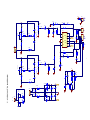
External input signals are inputted to input board by SC1, and its left channel signal outputs to pin 3
of socket XS through R127, to power amplifier board through flat cable XP2; after reaching power
amplifier board, it is divided into 2 paths, one path reaches potentiometer RP100A for bass adjustment
through R100 (RP100 is duplicate potentiometer, which can adjust left and right channels at the same
time); the other paths reaches potentiometer RP101A for treble adjustment through capacitor C100
(RP101 is duplicate potentiometer, which can adjust left and right channels at the same times); and the
two paths combine one path after treble/bass adjustment through resistor R108, R107 to send to
potentiometer RP102A for volume adjustment (RP102 is duplicate potentiometer, which can adjust left
and right channels); volume adjustment signals, through R101 damping and C101 coupling, are sent to
pin 11 of N100 TDA7265 for power amplifying (TDA7265 is a dual-channel power IC), then output
signals through pin 2 after amplification to loudspeaker directly. Signal floe direction of right channel is
similar with that of left channel.
This player is with power-on mute function, and its principle is: when power on, +VS charges
capacitor C110 through R110, triode V100 cuts off, MUTE pin of TDA7265 inputs high level, mute of
TDA7265 is effective, the whole set has no output; when capacitor C110 is in charging, positive voltage
increases to 6V, V100 is on, MUTE turns into low level, mute is off, output is normal and the concussion
sound is removed when power on .
2. Troubleshooting flow
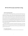
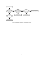
(1) Troubleshooting flow for “Left channel has no output”os shown as the following figure 2.1:
-1-