1
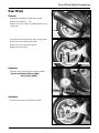
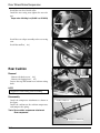
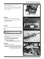
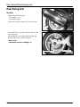
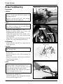
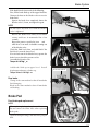
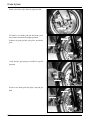
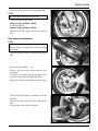
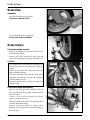
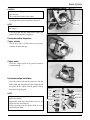
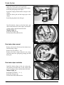
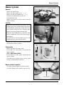
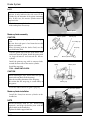
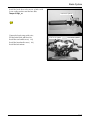
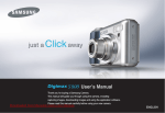
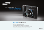
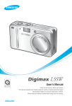
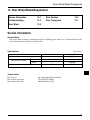
Rear Wheel/Brake/Suspension 13. Rear Wheel/Brake/Suspension Service Information 13-1 Rear Cushion 13-4 Troubleshooting 13-2 Rear Swing Arm 13-7 Rear Wheel 13-3 Service Information General Safety ƃ If the brake drum or lining is contaminated with oil, braking power will be lost. If contaminated with oil, clean the brake drum, and replace the brake shoe. Specifications Item Standard value Axle shaft run out Rear wheel rim runout Unit: mm(in) Service limit - 0.2(0.008) Radical - 2.0(0.08) Axial - 2.0(0.08) 245 238 Rear cushion spring free length Torque values: Rear axle nut Rear cushion upper bolt Rear cushion lower bolt 6.0~8.0kg-m(60-80N.m, 43-58ft-lb) 2.7kg-m(27N.m, 20ft-lb) 4.0kg-m(40N.m, 29ft-lb) 13-1 Rear Wheel/Brake/Suspension Troubleshooting Wobble or vibration in motorcycle ƃ Tire pressure incorrect ƃ Faulty tire ƃ Bent rim ƃ Loose wheel bearing ƃ Swing arm bushing worn ƃ Wheel out of balance Soft suspension ƃ Weak springs ƃ Shock absorber improperly adjusted Hard suspension ƃ Shock absorber improperly adjusted ƃ Bent shock absorber rod Suspension noise ƃ Loose fasteners ƃ Worn shock 13-2 Rear Wheel/Brake/Suspension Rear Wheel Removal ƃ Support the motorcycle on the main stand. ƃ Remove the muffler. (ऺ 4-9) ƃ Remove the rear caliper assembly from the rear swing arm. Muffler ƃ Loosen the rear axle nut, remove the rear swing arm. ƃ Remove the rear wheel inside collar. ƃ Remove the rear wheel mud guard. ƃ Remove the rear wheel. Rear caliper Rear axle nut Rear swing arm Inspection ƃ Turn the wheel, and check the rim for wobbles. Service limit:Radical 2.0mm (0.08in) Axial 2.0mm (0.08in) Installation ƃ Insert the rear wheel over the drive shaft. Drive shaft 13-3 Rear Wheel/Brake/Suspension ƃ Install the rear wheel inside collar. ƃ Install the rear swing arm, tighten the rear axle nut. Torque value: 6.0-8.0kgf m (60-80N m, 43-58ft-lb) Rear wheel Axle nut ƃ Install the rear caliper assembly to the rear swing arm. ƃ Install the muffler.(ऺ 4-9) Rear Cushion Removal Setting bolt - Remove the body cover.(ऺ 4-6) - Remove the luggage box.(ऺ 4-5) ƃ Loosen the top and bottom rear cushion setting bolts. NOTE Ү Support the frame firmly prior to working. Disassembly ƃ Install the compressor attachment as shown in the figure. ƃ Install the cushion on the cushion compressor, and compress the spring. Tools: Rear cushion compressor attachment Rear compressor Cushion compressor Compressor attachment 13-4 Rear Wheel/Brake/Suspension ƃ Fix the bottom metal, and loosen the lock nut. ƃ Remove the bottom metal. ƃ Remove the lock nut, bottom metal, stopper rubber, spring, and spring guide from the damper component. Lock nut Bottom metal Inspection Spring ƃ Measure the rear cushion spring free length. ƃ Check the damper rod for deflection or damage. Service limit: 238mm Assembly Free length ƃ Assemble the spring, spring guide, and stopper rubber. NOTE ҮInstall the spring with its narrow pitch side facing upward ƃ Apply thread locking agent to the lock nut, and install the rear cushion compressor attachment on the damper rod. ƃ Fix the upper joint, and tighten the lock nut. Torque value: 2.0kg-m(20N.m, 14ft-lb) Tools: Rear compressor Rear cushion compressor attachment Cushion compressor Compressor attachment Installation ƃ Assemble the rear cushion. ƃ Tighten the top and bottom of the cushion with bolt. Torque value: Upper side 2.7kg-m(27N.m, 20ft-lb) Lower side 4.0kg-m(40 N.m, 29ft-lb) Setting bolt 13-5 Rear Wheel/Brake/Suspension Rear Swing Arm Removal ƃ Remove the following parts. - EX. muffler.(ऺ4-9) - Rear brake caliper. ƃ Loosen the axle nut, remove the rear swing arm. Muffler ƃ Disassemble the rear wheel outside collar to the rear swing arm. ƃ Disassemble the oil seal and radial ball bearing. ƃ Install in the reverse order of removal. Torque value - Rear wheel axle nut: 6.0-8.0kgf m Rear brake caliper 13-6 Rear swing arm Brake System 14. Brake System Service Information 14-1 Brake Disk 14-6 Troubleshooting 14-1 Brake Caliper 14-6 Brake Fluid/Bleeding 14-2 Master Cylinder 14-9 Brake Pad 14-3 Service Information General Safety ƃ Do not allow foreign material to enter the system when replenishing brake fluid. ƃ To prevent chemical changes, do not mix different types of brake fluid. ƃ Do not use the old brake fluid again. ƃ Brake fluid can cause damage to painted, plastic, and rubber surfaces. Take precautions not to allow parts to be contaminated by the brake fluid. ƃ Do not reuse sealing washers. ƃ Clean the disassembled parts with brake fluid, and check for any clogged passage with compressed air. ƃ Bleed the brake hose after removing it. Troubleshooting Braking power unsatisfactory ƃ Air in the brake system ƃ Moisture in brake fluid ƃ Brake pad and disk contaminated ƃ Caliper piston seal worn ƃ Master cylinder piston seal worn ƃ Brake pad worn ƃ Caliper inside contaminated ƃ Unsatisfactory caliper sliding part operation ƃ Lopsided wear of brake pad and disk ƃ Low brake fluid level ƃ Clogged brake fluid line ƃ Disk bent or distorted ƃ Caliper piston seized or worn ƃ Master cylinder piston seized or worn ƃ Disk worn ƃ Master cylinder inside contaminated ƃ Brake lever bent Hard brake lever movement or unsatisfactory return ƃ Brake system clogged ƃ Caliper piston seized or worn ƃ Unsatisfactory caliper sliding part operation ƃ Brake fluid line clogged ƃ Caliper piston seal worn ƃ Master cylinder piston seized or worn ƃ Brake lever bent Brake drag ƃ Brake pad and disk contaminated ƃ Improper wheel alignment ƃ Lopsided wear of brake pad and disk ƃ Disk bent or distorted ƃ Unsatisfactory caliper sliding part operation ƃ Hydraulic system contaminated with dust. 14-1 Brake System Brake Fluid/Bleeding Brake hose bolt Front master cylinder Front brake CAUTION ҮA contaminated disk or pad reduces braking power. Do not allow the disk or pad to be contaminated by oil. ҮReplace contaminated pads, and remove pollutants from the disk completely. NOTE ҮCheck the brake fluid level often, and replenish new fluid as required. Do not spill fluid on painted, plastic or rubber parts. ƃ Remove the front handle cover. (ਨ4-8) ƃ Remove the master cylinder cap, set plate, and diaphragm from the master cylinder. ƃ Connect the bleeder hose to the bleeder valve. Loosen the bleeder valve, and pump the brake lever repeatedly. ƃ When there is no more fluid flowing out of the bleeder valve, stop pumping the brake lever. Bleeder valve Bleeder hose Air Bleeding ƃ Fill the reservoir with DOT3 or 4 brake fluid up to the upper level. CAUTION ҮTo prevent chemical changes, do not use different types of brake fluid. ƃ Connect the recommended brake bleeder to the bleeder valve. ƃ Loosen the bleeder valve while pumping the brake lever. ƃ Repeat this operation until the brake fluid flows out of the brake bleeder. ƃ Add brake fluid. NOTE ҮCheck fluid level often, and replenish fluid if the amount of fluid is reduced to the lower level. ҮRead the user ’s manual carefully prior to disassembling or using the brake bleeder. ҮProtect the bleeder valve with tape to prevent air from entering the bleeder valve. ƃ Repeat the above operation until there is no air flowing out of the bleeder hose. ƃ Squeeze the bleeder valve and operate the brake lever to check the ingress of air. 14-2 Bleeder valve Brake System ƃIf the brake bleeder is not used, do the following. ƃFirst, fill the brake fluid up to the upper limit line. Connect the hose to the bleeder valve to receive brake fluid. ڹSqueeze the brake lever completely loosen the bleeder valve 1/2 turn, and tighten it again. NOTE ҮDo not release the brake lever until the bleeder valve is tightened. ںRelease the brake lever slowly to its fullest extent, and leave it unattended for a few seconds. ڻRepeat the process specified in item ڹand ں until there is no more air bubbles coming out of the bleeder valve. ƃ Check the fluid level often, and add fluid if the fluid level is near the lower level. ƃ If no air leaks out of the bleeder hose, operate the brake lever to check the presence of air. ƃ Assemble the bleeder valve. Torque: 0.4-0.7kgfŋm ƃ Add brake fluid up to upper level. Install diaphragm and mater cylinder cap. Torque value: 0.1-0.2kgfŋm Bleeder valve Bleeder hose Rear mater cylinder Rear brake ƃ Change in the same method as that of front brake fluid changing. ƃ Bleed in the same method as that of front brake air bleeding. Rear brake caliper Brake Pad Front brake pad replacement NOTE ҮWhen replacing brake pads, replace whole set. ҮDo not remove the brake hose when replacing brake pads. ƃ Open the lock plate tangs, and loosen the pad pin bolt. Fixing Bolt 14-3 Brake System ƃ Remove the brake caliper from the right front fork. Brake caliper ƃ To install a new brake pad into the brake, press the piston to return to the original position. ƃ Remove the pad pin bolt, lock plate, and brake pad. Lock plate Brake pad Pin bolt ƃ Verify that the pad spring is installed in specific position. Pad spring ƃ Install a new brake pad, lock plate, and pad pin bolt. Lock plate Brake pad Pin bolt 14-4 Brake System ƃ Install the brake caliper into the right front fork. NOTE ҮBe careful not to damage the brake pad. ƃ Tighten the caliper braket bolt. Torque: 2.7kgŐm(27N.m, 19ft-lb) ƃ Install pad pin bolt. Torque: 1.8kgŐm(18N.m, 13ft-lb) ƃ Bend the lock plate tangs, and fix the pad pin bolt. Brake caliper Rear brake pad replacement NOTE ҮWhen replacing brake pads, replace whole set. ҮDo not remove the brake hose when replacing brake pads. ƃ Open the lock plate tangs, and loosen the pad pin bolt. Muffler ƃ Remove the EX. muffler.(ਨ4-9) ƃ Remove the rear brake caliper from the rear swing arm. ƃ To install a new brake pad into the brake, press the piston to return to the original position. ƃ Remove the pad pin bolt, lock plate, and brake pad. Rear brake caliper ƃ Verify that the pad spring is installed in specific position. ƃ Install a new brake pad, lock plate, and pad pin bolt. ƃ Install in the reverse order of removal. Brake pad Pin bolt 14-5 Brake System Brake Disk Inspection ƃ Measure the thickness of the disks. Thickness: 3.0mm(0.1181in) ƃ Check the brake disks for vibration. Service limit: 0.02mm(0.0008in) Brake Caliper Front brake caliper removal ƃ Remove the brake oil bolt and the brake hose from the brake caliper. ƃ Remove the caliper from the R. front fork and remove the pad spring, hanger pin and brake pad. CAUTION ҮPay attention not to let the brake fluid adhere to the parts because it can damage the painted surface. ҮWind the hose joint with cloth to prevent the brake fluid from leaking. ҮClean the removed parts with the brake fluid and make sure that the each port isn t clogged with the compressed air. ҮKeep the removed parts in order to avoid dust from adhering. Brake hose Oil bolt Front brake caliper disassembly ƃ Remove the slide pin, the L. bracket, the pin bush, the boot and the pin boot, and the pin bolt from the caliper. ƃ If there is any wear or damage in the boot, replace it with the new one. ƃ Wind the caliper with cloth to prevent the piston or brake fluid from leaking. ƃ Remove the piston from the caliper while blowing the low-pressure air in the opening of the brake hose. 14-6 Air gun Caliper Brake System CAUTION ҮNever use the high-pressure air or bring the air gun too close. ҮNever touch the inside of the caliper. ƃ Disassemble the piston seal and the dust seal. Dust seal NOTE ҮPay attention not to damage the inner surface of the caliper. Piston seal ƃ Clean the piston and the inside of the caliper and remove the oil from the seal groove. Front brake caliper inspection Caliper cylinder ƃ Check the caliper cylinder bore for scoring, scratches or other damage. Caliper piston ƃ Check the caliper piston O.D. part for scratches or other damage. Front brake caliper installation ƃ Clean the piston seal and the dust seal with the brake fouid and install them in the caliper. Install the piston in the caliper with the groove side of the piston facing the pad. NOTE ҮMake sure that each part is free from dust or dirt before reassembly. ҮReplace the dust seals and piston seals as a set whenever they are removed. ҮWhen cleaning with the brake fluid, use the specified brake fluid. Tongued washer Rear bracket pin bush pin hanger Slide pin Dust seal Pad spring Pad Piston seal Piston 14-7 Brake System ƃ Apply the silicone grease to the pin bush. ƃ Connect the pin bush to the portion of the caliper. ƃ Install the pad spring in the caliper. ƃ Install the caliper pin bolt and the slide pin in the caliper. ƃ Install the brake pad and the hanger pin in the caliper. ƃ Install the plug dust in the slide pin. ƃ Install the brake caliper to the front fork, and connect the brake hose to the caliper, and install 2 sealing washers and the brake hose bolt. Torque: 3.5kgfŋm ƃ Install the slide pin cap. ƃ Fill the brake fluid, and bleed air. Front brake caliper Rear brake caliper removal ƃ Remove the brake oil bolt and the brake hose from the brake caliper. ƃ Remove the EX. muffler. (ਨ4-9) ƃ Remove the brake caliper from the rear swing arm and remove the pad spring, hanger pin and brake pad. Rear brake caliper Rear brake caliper installation ƃ Install the brake caliper to the rear swing arm, and connect the brake hose to the caliper, and install 2 sealing washers and the brake hose bolt. Torque: 3.5kgfŋm ƃ Install the EX. muffler. (ड 4Ő9) ƃ Install the slide pin cap. ƃ Fill the brake fluid, and bleed air. EX.muffler 14-8 Brake System Master Cylinder Front master cylinder Rear master cylinder Removal ƃ Remove the back mirror. ƃ Remove the front handle cover.(ड 4Ő8) ƃ Remove the the rear handle cover.(ड 4Ő8) ƃ Disconnect the front brake switch wire. ƃ Drain the brake fluid. ƃ Remove the front/rear brake hoses from the master cylinders. CAUTION ҮBrake fluid causes damage to the painted, plastic or rubber parts. Do not spill fluid on these parts. ҮIf contaminated, gently wipe off the fluid with a piece of cloth or wash in water. Close hose joints properly to prevent leakage of brake fluid. ҮClean the disassembled parts with brake fluid, and use compressed air to verify each passage is not clogged. ҮDo not allow the disassembled parts to be contaminated by waste material or dust. Oil bolt ƃ Remove the front/rear master cylinder holder, and lift out the master cylinder. Disassembly ƃ Remove the front/rear stop switch. ƃ Disassemble the piston boot, cir clip from the master cylinder. TOOL : SNAP RING PLIERS ƃ Disassemble the washer, piston, spring from the master cylinder. ƃ Clean the master cylinder, reserve, master piston with the recommended brake fluid. Stop switch Master cylinder set Master cylinder inspection ƃ Check the piston periphery for kink or scratch. ƃ Check the primary and secondary cups for wear. Master cylinder 14-9 Brake System NOTE ҮIf there is any leak of fluid when installing new piston, it may indicate the side wear of the cylinder by the direction of the piston contacting face. In this case, the master cylinder must be replaced also. ƃ Chack the master cylinder for scores, scratches or nicks and replace if necessary. Master cylinder Master cylinder assembly CAUTION ҮReplace the piston, spring, cups and snap ring as a set. ҮBe sure that each part is free from dust or dirt before reassembly. ҮWhen cleaning with the brake fluid, use the specified brake fluid. ƃ Coat the piston cup with the fresh brake fluid and install it on the piston. Install the spring with its larger diameter end toward the master cylinder. ƃ Install the primary cup with its concaved side toward the inner side of the master cylinder. ƃ Install the snap ring. TOOL : SNAP RING PLIERS Master cylinder Primary cup Secondary cup Snap ring Spring Master cylinder Spring Master piston CAUTION ҮWhen installing the cups, do not allow the lips to turn inside out.(Refer to the drawing.) ҮNote the installing direction of the snap ring. ҮBe certain that the snap ring is seated firmly in the groove. ƃ Install the rubber boot in the groove properly. Master cylinder installation ƃ Install the front/rear master cylinder to the handle bar. NOTE ҮInstall the holder with its UP mark facing upwards, and align the holder joint with the punch mark on the handle bar. ҮTighten the holder upper bolt first. 14-10 Primary cup Front master cylinder Brake System ƃ Inatall the brake hose to the master cylinder with 2 new sealing washers and the hose bolt. Torque: 3.5kgfŋm ƃ Connest the brake stop switch wire. ƃ Fill the brake fluid, and bleed air. ƃ Install the rear handle cover.(ਨ4-8) ƃ Install the front handle cover.(ਨ4-8) ƃ Install the back mirror. Rear master cylinder Front master cylinder Rear master cylinder 14-11 MEMO