1
FAULT CODE READER
Audi / Volkswagen
Vehicles with Fuel Injection or Electronic Control Units
PART NO G4155
HANDBOOK
Gunson Fault Code Reader
2
Gunson Fault Code Reader
Fault Code Reader
for Petrol Engines
Audi / Volkswagen
For vehicles with fuel injection or
electronic control units
INDEX
Contents
Page
1. Safety First
4
2. How Fault Codes make it easy
5
3.The Fault Code Reader
7
4. How to use the Fault Code reader
7
5. Connection
8
6. Display codes
9
7.Vehicle applications
10
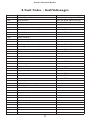
8. Fault Codes – Audi/Volkswagen
10
9.Test procedure notes (TPN)
12
10. Common terms
17
11.Warranty and customer service
19
Gunson Fault Code Reader
1. SAFETY FIRST
General safety guidelines to follow when working on vehicles
• Always operate the vehicle in a well ventilated area.
• Do not inhale exhaust gases - they are very poisonous.
• Always make sure the vehicle is in park (Automatic transmission) or neutral
(manual transmission) and that the parking brake is firmly set. Block the
drive wheels.
• Always keep yourself, tools and test equipment away from all moving or hot
engine parts. Treat high tension ignition components with respect,
remembering that electrical shocks can cause involuntary movement which
may result in secondary injury.
• Wear approved eye protection.
• Never wear loose clothing that can catch in moving engine parts and always
tie-up or cover long hair.
• Never lay tools on a vehicle battery. You may short the terminals together
causing harm to yourself, the tools or the battery.
• When carrying out tests on a motor vehicle, remember NEVER run the
engine with the car battery disconnected (either + or -) since the alternator
would then run at a damaging over-voltage.
• Never smoke or have open flames near vehicle. Vapours from gasoline and
charging battery are highly flammable and explosive. Always keep a suitable
fire extinguisher handy.
• Never leave vehicle unattended while running tests.
• Keep children and animals out of the area.
• Always turn ignition key OFF when connecting or disconnecting electrical
components, unless otherwise instructed.
• Always follow vehicle manufacturer's warnings, cautions and service
procedures.
CAUTION
Some vehicles are equipped with safety air bags. You must follow vehicle
service manual cautions when working around the air bag components or
wiring. If the cautions are not followed, the air bag may open up
unexpectedly, resulting in personal injury. Note:The air bag may still open up
several minutes after the ignition key is off (or even if the vehicle battery is
disconnected) because of a special energy reserve module.
4
Gunson Fault Code Reader
Precautions to be followed when using the Fault Code Reader
• Before connecting the leads, ensure that the correct connector of the car has
been identified.
• Using this product may cause vehicle systems to self test, items such as
coolant fans to suddenly start with no warning, and engine speed to
suddenly increase.
• Using this product can involve working on a car while the engine is running.
This is a potential hazard and the user should take every precaution to avoid
any possibility of damage or injury.
2. HOW FAULT CODES MAKE IT EASY
Modern vehicles have electronic control units that are able to identify and
remember faults which occur in the vehicle's equipment. This system was
introduced on the higher specification electronic fuel injection vehicles around
1986 and was applied to other types of ECU a little later(ABS and Ignition) Its
application is now virtually universal to all petrol engine vehicles. This is a
great benefit to service and maintenance personnel as it can considerably
simplify vehicle repair. The vehicle faults are stored in the vehicle's Electronic
Control Unit (ECU) as "Fault Codes".
The system is so simple that retrieving vehicle fault codes does not require
particular skill. However, in order to read these fault codes some equipment
is necessary. (E.g. a Fault Code Reader), which is used to instruct the vehicle's
ECU to download fault codes and/or present them to the user on a display. By
far the most common system is to present the code as a “blink code”. The
Fault Code Reader will activate that part of the OBD programme which
identifies the defective component and cause a code to be displayed, usually by
a light on the Fault Code Reader or by an instrument panel "Check Engine"
light. These provide a series of pulses to simply count a code number. Systems
with an instrument panel “Check engine” light are able to illuminate this when
the engine is running to warn of faults, other systems are more secretive and
need to be interrogated.
The Fault Code Reader is an economical but very effective product. It is
available for a wide range of vehicles and enables the user to instruct the
vehicle to download stored fault codes. Having obtained the fault codes, the
user then identifies the nature of faults by referring to a list of code numbers.
Comprehensive lists of code numbers are included in this handbook.
5
Gunson Fault Code Reader
NB Car manufacturers have in the past used a connector type unique to
their own cars. Many manufacturers have used different types of connector at
various times. Only recently have there been moves to standardise to a 16 pin
socket.
Makes and models of car also vary in the degree of testing and fault
diagnosis that is possible. In general, the ECU will identify faults that exist at
the time of the test, but the ECU may also have a memory that remembers
faults that have occurred in the recent past, and these can also be read out
from memory using the Fault Code Reader. For instance, in some vehicles, the
readout consists of the faults that are present at that time, followed after a
“separator” code, by the codes that are held in memory from some previous
time.
In most vehicles, tests are carried out with the engine off (but ignition on).
Occasionally additional tests may be carried out with the engine running (this
depends on the sophistication of the ECU and is not available on all makes of
vehicle).
Having identified the fault codes, and eliminated the faults, the user may
then wish to erase the faults from the ECU's memory.With some cars this is
possible using a special sequence of operations, or a sequence of switch
operations on the Fault Code Reader. With other vehicles this is not possible
and it may be necessary to erase the memory by disconnecting the battery
(-) connection (with engine not running), this has the disadvantage that codes
for radio/ security system and also some ECU memory settings are
temporarily lost. Fault codes generally disappear anyway after the fault has
not been present for a certain number of engine start cycles, but deletion of
the codes followed by a short drive has the advantage that it allows the
operator to check if the fault has truly been rectified. This is confirmed if the
code does not re-occur.
Before using this product (or indeed carrying out any vehicle maintenance),
the user is recommended to read the precautions presented in later sections
of this manual. In particular, note that during the use of this product the
vehicle's On Board Diagnostic programme (OBD) takes control of the vehicle,
and may activate various vehicle systems (such as turning on the cooling fan),
this can constitute a safety hazard and the user should keep fingers clear
during tests.
6
Gunson Fault Code Reader
3.THE FAULT CODE READER
Fault Code Reader is complete with the connections
for the vehicle listed on the packaging. It is not suitable
for use on any other vehicle
INSTRUCTIONS FOR USE please read carefully and it
will help you to use the product and interpret the
information it can provide
TEST SWITCH. Labelled “0" and “I”. Moving from “0"
to “I” starts a test or changes the way the vehicle’s
Electronic Control Unit (ECU) functions.
LED CODE INDICATOR. (If fitted), will transmit
pulses which represent the fault codes. On models where
this is not fitted the pulses will generally be seen on the
engine check light on the vehicle instrument panel.
4. HOW TO USE YOUR FAULT CODE READER
NUMBER / CODE IDENTIFICATION
Identifying fault codes is in fact very easy and simple, though it may seem
complicated at a first reading, the user will soon get accustomed to the
technique.
Basically, the ECU communicates with the “Code Reader” in a series of
pulses, and the user simply counts these pulses to identify particular numbers.
For example, the number 6 would be transmitted as 6 pulses in rapid
succession. If we use the symbol R to indicate a pulse, then the number 6 will
be transmitted as:
R
R
R
R
R
R
= 6
If the number is a 2 digit number, then each digit is transmitted separately. For
example, the number 25 would be represented as 2 pulses, followed by a brief
pause, and then 5 more pulses.
R
2
R
R
R
R
5
R
R
=
7
25
Gunson Fault Code Reader
In practice, the ”Fault Code Reader” code will be output as a series of
numbers one after the other, and the user has to recognise individual numbers,
and recognise the gaps between numbers. This is made easy by the fact that
the pause between two numbers is much greater than the pause between the
individual digits of a number.
Similarly, there is an even greater pause between one series of code numbers
(egg representing current faults), and another series of code numbers (e.g.
representing faults stored in memory.
To make matters even easier, the ECU, in most instances, repeats a series of
code numbers, so that the user has the opportunity to check the reading.
Each code has a particular meaning, which is identified by reference to the
tables of Fault Codes which follow.
GENERAL NOTES
Before connecting “the Fault Code Reader” to the car, the user should
ensure that the TEST SWITCH is set to "O" and the diagnostic socket has
been correctly identified. Check that the car ignition is off, the car is out of
gear, and that the handbrake is applied.
When a fault code appears, it does not necessarily mean that the component
indicated is faulty. It could mean that the ECU has received a signal from the
component or it's wiring, which is outside specification.
Therefore before tests are performed, (using the Test Procedure Notes later
in this Manual), it is important
all of the connections and wiring associated with the indicated component are
checked.
When multiple faults are indicated, it is possible that the fault on one
component is causing incorrect readings from other components, but all the
components will have to be checked to eliminate the true cause.
5. CONNECTION
DIAGNOSTIC SOCKET LOCATION
The diagnostic socket is usually located close
to the ECU or the main relays in the engine
compartment. It is a two pin socket with Female
contacts, the moulding is usually green
8
Gunson Fault Code Reader
Fault Code Reader connection:
Flat blade connector to socket A
Alligator Clip to battery earth
FAULT INDICATION AND DISPLAY TYPE
It is normal for Citroen / Peugeot vehicles to have an engine check light fitted to the instrument
panel. If a significant continuous fault is present this light should be illuminated. An intermittent
fault may record a code without setting the engine check light.
The engine check light is orange in appearance, has a small engine silhouette with a transistor
symbol on it. It should illuminate with the ignition ON and engine not running to check the bulb
and wiring.
FAULT STORAGE MEMORY
This facility is included. Intermittent fault detection will result in a code being set. After a number of repeat vehicle journeys without a fault, the code may be automatically deleted.
6. DISPLAY CODES
Carry out a basic inspection under the bonnet before proceeding, ensuring that all leads and
connectors are secure and the ignition is turned off.
TEST PROCEDURE
1. Set the ”Code Reader” switch to the O position and connect the Code Scanner to
the diagnostic socket (Fig 1)
2. Turn on the ignition ON but do not start the engine.The LED will be ON
3. Set the Code Reader switch in the l position for a period of approximately three
seconds, then return it to the 0 position.
The LED will now come ON. After five seconds a further fault code may be transmitted
4. After a further five seconds the LED will extinguish.
5. Set the switch into the I position again for three seconds and then return to the 0
position, the LED will now come on. After about five seconds the next code will be transmitted.
6. Wait for five seconds and the Code Reader LED will extinguish, if a fault code was
transmitted, set the switch into the I position again for three seconds and then return to
the 0 position. After about five seconds a further fault code may be transmitted.
7. This switch sequence must be repeated until code 1111, end of test, is transmitted.
8. The test can be repeated in order to confirm any codes or terminated by switching off the
ignition and disconnecting the Code Reader.
Reference should be made to the Fault Code Table to identify any codes and to assist in repair
procedures.
CLEARING CODES (AFTER CORRECTING ANY VEHICLE FAULTS)
9
Gunson Fault Code Reader
When the end of the test procedure is indicated by the end of code 11, there will be a pause of
about five seconds and the LED will extinguish.
1. Put the switch into the I position for about ten seconds.Then put the switch into the 0 position,
and switch off the ignition.
2. Perform the test procedure again to ensure that the fault codes have been deleted.
3. Drive the vehicle sufficient to warm the engine fully and then operate it under a variety
of part and full load conditions.
4. Perform the test procedure again to ensure that the fault codes have not been reset.
Actuator Test (AUDI V8 MOTRONIC ONLY)
1. Set the Fault Finder switch to the O position and connect the Fault Finder to the diagnostic
socket
2. Turn on the ignition but do not start the engine
3. Set the Fault Finder switch to the I position for a period of approximately ten seconds, then turn
to the O position. Fault codes will be transmitted as a series of pulses.
4. Set the Fault Finder switch in the I position again for three seconds then return it to the O
position. After five seconds a further fault code may be transmitted.
This switch sequence must be repeated until code 1111 End of test is transmitted.
After all codes have been transmitted fully open the throttle. When the throttle is returned to
the closed position, the actuator test will start. Injector valve 1 will be activated 4 times, then
injector valve 3 and so on. After all injector valves have been operated the idle speed control valve
will be activated followed by the carbon filter solenoid.
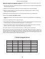
7.Vehicle Applications
Audi
80
1.6/2.0
ABM/ABT
-1993
100
2.6 V6
ABC
-1993
4.2 V8
ABH
-1993
1.4/1.8
ABD/AMM/ABS
Golf
2.0 16v
ABF
Golf/Vento
2.0 8v
2E
Golf/Vento
2.8 VR6
AAA
Passat
2.8 VR6
AAA
Passat
2.0 16v
9A
Passat
1.8
AAM
Volkswagen Golf/Vento
10
Gunson Fault Code Reader
8. Fault Codes - Audi/Volkswagen
1111
ECU faulty
1231
Vehicle Speed Sensor
Test for speed signal to ECU
2111
RPM Sensor
Test for RPM signal to ECU
2112
TDC Sensor
Test for TDC signal to ECU
2113
Hall Effect pick-up
2114
Hall effect sensor position
2121
Throttle position sensor/idle switch
Refer to TPN 4/5
2123
Throttle position sensor/full load
Refer to TPN 4/5
2141
Knock control 1
2142
Knock control 1
2143
Knock control 2
2144
Knock control 2
2212
Throttle position sensor/full
2214
Max engine speed exceeded
2221
Throttle position sensor idle
Refer to TPN 4/5
2222
MAP sensor
Refer to TPN 6
2223
Altitude sensor
2224
Max boost pressure exceeded
2231
Idle speed control outside control range
2232
MAF potentiometer
2234
Power supply
2242
CO potentiometer
2312
Coolant temp sensor
2314
Engine/Gearbox switch circuit
2322
Air temp sensor
Refer to TPN 3
2323
Mass air flow potentiometer
Refer to TPN 7
2324
Mass air flow sensor
Refer to TPN 7
2411
Exhaust gas recirculation
2413
Mixture adaptive range exceeded
4332
ECU faulty
4343
Carbon filter solenoid valve
4411
Injector valve 1
4412
Injector valve 2
4413
Injector valve 3
4414
Injector valve 4
4421
Injector valve 5
4422
Injector valve 6
4423
Injector valve 7
4424
Injector valve 8
4431
Idle speed control
4444
No fault found
Refer to TPN 4/5
Refer to TPN 7
Refer to TPN 2
11
Gunson Fault Code Reader
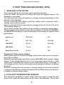
9.TEST PROCEDURE NOTES (TPN)
1. VANE AIR FLOW METER
This is positioned in the airstream and is opened by the flow
of the air intake. The greater the airflow, the more the flap/plate opens. The
flap/plate is connected
to a potentiometer that will produce a voltage reading proportional to the
position of the flap/plate.
To test a Vane Air Flow Meter, probe the airflow meter connector with a
voltage meter until the sensor
output is identified.The output will be a voltage of 0.5v to 4.5v, or 4.5v to 9v.
The reading changes as
the air flow is varied. The airflow can be varied by varying the engine speed.
Test the output of the airflow meter with the ignition on, at idle, at 1500 RPM,
at 3000 RPM, and during a rapid acceleration, and compare to typical values
given below:
Ignition on
0.25v-0.5v
3.5v
Idle
0.5v-1.5v
4.5v-5.0v
1500 RPM
0.7v-2v
5.0v-5.5v
3000 RPM
1.1v-3v
6-7v
Rapid Acceleration
3v-4.5v
>8v
Typical Air Flow sensor output
Most systems give an increase in voltage with air flow rate, but some systems
give a fall in voltage.
Gradually increase engine speed from idle to 3000 RPM, observing the voltage
change. If the voltage becomes 0v or 5v at any point, repeat the test. If the
same result is obtained, the resistive track of the airflow meter is damaged. If
the voltage stays at a value as the engine speed changes it indicates a sticking
flap/plate.
A sensor simulator that can simulate a varying voltage, can be used to provide
a voltage to the ECU to simulate the output of the airflow sensor and positively diagnose a faulty airflow meter.
2. COOLANT TEMPERATURE SENSOR:
This should be tested by an ohms meter when the engine is cold, and also
when warm (with any connections to the sensor disconnected). The results
12
Gunson Fault Code Reader
should be checked against manufacturer’s specifications, or typical values as
given overleaf:
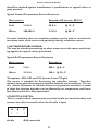
Typical Coolant Temperature Sensor Resistance
Most systems
Exception KE Jetronic, EEC1V.
Cold
3-5 K Ω
50 K Ω
@ 15∞C
Warm
300-400 Ω
3.5 K Ω
@ 80∞C
A sensor simulator that can simulate resistance can be used to simulate the
resistance value of the sensor and positively identify a defective sensor.
3 AIR TEMPERATURE SENSOR:
This may be tested by connecting an ohms meter across the sensor and checking against the typical values given below:
Typical Air Temperature Sensor Resistance
Exceptions*
Most systems
Cold
5KΩ
500 Ω @ 0∞C
Warm
2.5 K Ω
200 Ω @ 20∞C
*Exceptions - KE,L,LE2 and LE3 Jetronic Lucas P Digital
The sensor is intended for fine-tuning the petrol/air mixture. Therefore
dynamic tests while observing the injection duration are inconclusive. The use
of a Sensor Simulator to simulate extreme temperature variations is useful
to show the injection duration can be affected by air temperature and therefore that the circuit is fully operational.
4.THROTTLE SWITCH:
This is a switch which connects two terminals at idle (or closed throttle), and
connect two other terminals when the throttle is open.
A
•
At idle
B
•
C
•
A+B connected
13
Gunson Fault Code Reader
Open throttle B+C connected
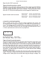
Typical throttle position switch
Therefore to test a throttle switch, connect an ohms meter across A + B. If the
throttle is closed then there should be 0 ohms across A+B. With the throttle
open, the reading should be open circuit or infinity. Connect the ohms meter
across B + C. Vary the throttle positions and the opposite should be true.
Throttle
Throttle
Throttle
Throttle
Typical throttle switch resistance
closed
open
closed
open
A to B = 0 Ω (closed circuit)
A to B = infinity (open circuit)
B to C = infinity (open circuit)
B to C = 0 Ω (closed circuit)
5.THROTTLE POTENTIOMETER.
This is variable resistor with a reference voltage supplied to the resistor. As
the throttle position changes the voltage on the output of the potentiometer
varies. This voltage informs the ECU of the exact position of the throttle. In
some cases the ECU measures the rate of change of throttle position, and so
a “clean” potentiometer track can be very important.
A
•
B
•
C
•
A = Variable Voltage : 0.5 to 4.5v
B+C = Resistor - fixed : 3K Ω - 10K Ω
Typical throttle potentiometer
To test the throttle potentiometer disconnect the connector to the sensor and
connect an ohms meter to terminals B and C. This is usually the fixed
resistance of the potentiometer. A resistance of between 3k-10k should be
observed. Re-connect the ohms meter to terminals A and B. A resistance of
0_-1k to 5k-10k should be observed between throttle closed and throttle open.
From throttle closed, slowly open the throttle, observing the steady change in
resistance. A rapid change in resistance or an open/ closed circuit reading
indicates a faulty sensor.
To further test the sensor, reconnect the connector to the sensor and start the
engine. Connect a voltage meter between terminal A and earth. Observe the
voltage at idle. Slowly open the throttle observing the change in voltage. The
14
Gunson Fault Code Reader
voltage is typically O.5v to 4.5v. A rapid change in the voltage, or a loss of the
voltage, indicates a faulty sensor.
If the sensor is not producing a producing a voltage, or the tests are
inconclusive, the use of a sensor simulator (to simulate the sensor output),
should be used to provide a voltage to the ECU. If symptoms persist while
using a Sensor Simulator, then the fault is not with the Throttle Position
sensor. If the system works correctly while the sensor is being simulated
(replaced) the sensor is positively identified as faulty.
6 MANIFOLD ABSOLUTE PRESSURE SENSOR:
This produces a voltage of 0.5 to 4.5v dependant upon the pressure/vacuum in
the inlet manifold.
The connector usually has three terminals. Use a voltage meter to identify the
5 volt supply, the ground, and the output voltage of the sensor.
Test the response of the sensor output relative to engine speed as for (1). If
there is little or no response, disconnect the vacuum pipe from the sensor and
apply a vacuum directly to the sensor. If the voltage now varies, check the
vacuum pipe for leaks or blockages. If the voltage does not vary with a direct
vacuum, it is likely that the sensor is defective.
To positively identify the MAP sensor as faulty, use a Sensor Simulator to
simulate the output of the sensor.
7. MASS AIR FLOW SENSOR:
This is a hot wire positioned in the air stream. The air flow through the air
intake has a cooling effect on the hot wire, and the greater the flow, the greater
the cooling effect. A control unit which regulates the temperature of the hot
wire provides a voltage signal to the ECU relative to the air flow.
To test a mass air flow sensor, probe the airflow meter connector with a
voltage meter until the sensor output is identified. The output will be a
voltage of 0.5v to 4.5v, or 4.5v to 9v. This voltage changes as the air flow is
varied. The airflow can be varied by varying the engine speed.
Test the output of the airflow meter with the ignition on, at idle, at 1500 RPM,
at 3000 RPM and during a rapid acceleration and compare to the typical
values below:
Ignition on
Idle
1500 RPM
3000 RPM
Rapid Acceleration
0.25v-0.5v
0.5v-1.5v
0.7v-2v
1.1v-3v
3v-4.5v
Typical Air Flow sensor output
Some systems produce a fall in the output voltage relative to an increase in air
15
Gunson Fault Code Reader
flow. A sensor simulator can be used to provide a voltage to the ECU to
simulate the output of the airflow sensor and positively diagnose a faulty
airflow meter.
8.PETROL TEMPERATURE SENSOR:
This measures the fuel temperature in the fuel manifold/pipe. If the
temperature exceeds 90∞C the ECU will enrich the mixture by increasing the
injection duration, as fuel evaporation is likely above 90∞C.
9.LAMBDA OR OXYGEN SENSOR:
This sensor is positioned in the exhaust system. It provides a voltage signal to
the ECU which is used to vary the injection duration to maintain an air/fuel
ratio of 14 parts air to 1 part of fuel.
A Lambda sensor tester is required to test the operation of this sensor. On
vehicles with a catalytic converter the Lambda sensor is essential as the
sensor enables the ECU to maintain an oxygen content of about 2% in the
exhaust. The catalytic converter requires the 2% of oxygen to perform its
function.
10. VALVES:
The ECU uses valves in the fuel system to pass or restrict fuel or gases
according to engine load conditions. Use the relay test to ensure that the ECU
is actuating the valve. Valves are mechanical devices which can be sticking or
jammed, therefore, removal and testing when removed from the vehicle may
be required.
16
Gunson Fault Code Reader
10. COMMON TERMS
Many abbreviated terms are peculiar to a particular manufacturer and are
explained in the relevant text. Some more common or universal ones appear
below.
COMPUTER SYSTEMS
ECU
ELECTRONIC CONTROL UNIT These units may control a separate
function, for example fuel injection, ignition, ABS. Modern systems
tend to be more multi- function as this saves cost, wiring complications
and ensures greater resistance to interference and more control over
emitted interference.
OBD
ON BOARD DIAGNOSTICS The facility provided by modern ECU’s
to self diagnose and report faults in the ECU, sensors, wiring
connections etc. Fault codes are used to differentiate faults.
KAM
KEEP ALIVE MEMORY A system for maintaining a record of faults
encountered to be accessed later. These may be intermittent or
recorded only under particular conditions and therefore not accessible
during no load testing.
IGNITION
DIS
DISTRIBUTOR LESS IGNITION SYSTEM. These use one coil per
cylinder or an arrangement which provides one coil per two cylinders
and sparks every rotation of the engine instead of every two rotations
(wasted spark). The net result is that H.T. voltages do not have to be
mechanically distributed. Together with ignition advance “mapping” in
the ECU this provides a high reliability and performance.
EDIS
ELECTRONIC DISTRIBUTOR LESS IGNITION SYSTEM
CID
CYLINDER IDENTIFICATION (SIGNAL) Determines which cylinder
is not only receiving a spark but is also on the compression stroke.
RON
Defines the OCTANE NUMBER of petrol. Multiple position
plug/socket arrangements allow ignition requirements to be changed
for different rated fuels. e.g. “octane multiplug”
17
Gunson Fault Code Reader
INJECTION/FUEL
LAMBDA SENSOR See EGO and HEGO sensors.
EGO EXHAUST GAS OXYGEN (SENSOR)
Sensitive to low
concentrations of oxygen in hot exhaust gas. Essential for accurate
“feedback” control of injection.
HEGO HEATED EGO (SENSOR)
MAP
MANIFOLD ABSOLUTE PRESSURE (SENSOR) Manifold pressure
sensor measures differential pressure with vacuum sealed capsule (not
atmospheric pressure).
MAF
MANIFOLD AIR FLOW (SENSOR) “Vane” or “hot wire” flow sensor.
SENSORS GENERAL
PTC
TEMPERATURE
SENSOR
of
POSITIVE TEMPERATURE
COEFFICIENT type. Low resistance when cold. NTC (NEGATIVE
TEMPERATURE COEFFICIENT)is low resistance hot.
ATS, FTS, CTS, TTS TEMPERATURE SENSORS
Transmission.
18
Air, Fuel, Coolant,
Gunson Fault Code Reader
11. WARRANTY AND CUSTOMER SERVICE
This warranty is in addition to the statutory rights of the purchaser.
The Tool Connection has made every effort to ensure that this product is of the highest quality
and value to the customer. However,The Tool Connection can accept no responsibility for
consequential damage howsoever caused arising from the use of this product.
All technical enquiries regarding this product should be made to:
The Tool Connection Technical Service Department: ++44 (0) 1926 818181
Please note that The Tool Connection cannot provide technical information or advice or service
data on particular motor vehicles.
If this product should require service or repair, it should be returned to:
The Tool Connection Technical Service Department,
Kineton Road,
Southam,
Warwickshire,
CV47 0DR,
England.
Please give full details of faults requiring attention when sending goods for service or repair
Gunson 08/2005
19