1
Exhaust system
Engine Auxiliary Systems
Course code: EN05
Student training manual
Suzuki Online Training
EN05 Engine Auxiliary System I Starting system
1
Foreword
Suzuki Technician curriculum
This training manual contains basic information on the exhaust
system. We will study exhaust system components and their
functions, the catalytic convertor and exhaust gas analysis
using the exhaust gas analyzer.
This training manual is part of the Non Suzuki Technician to
Suzuki Technician curriculum. The curriculum consists of the
following modules:
After your have completed this course, also complete the
relevant section in the “Practical Activities Student Workbook”
and the online test.
Smart manuals
Some sections of this training manual contain videos with
detailed information on the topics you are studying. If you are
studying this training manual on a PC, look out for the “green
play video” symbol on any part of this training manual, click on
the green button to watch a video providing you with detailed
information on that topic. Note: Internet connection required.
This document is intended solely for training purposes only.
All vehicle repairs and adjustments must be carried out
according to the procedures stipulated in current service
manuals and technical bulletins.
EN05 Engine Auxiliary System I Starting system
1. GE01 Suzuki Introduction
2. GE02 Electrical and Electronics
3. Diagnostics
4. EN02 Engine Mechanical part I
5. En03 Engine Mechanical part II
6. EN04 Engine Mechanical part III
7. EN05 Engine Auxiliary systems
8. DS01 Driveshaft/Axle
9. DS02 Driveshaft/Axle transfer case
10. BR02 Brake control systems
11. Manual transmission / transaxle
12. CS02 Control system / body electrical
13. CS03 Communication / bus systems
You are currently studying EN05 Engine Auxiliary Systems.
This module consists of the following courses:
• Charging systems
• Starting systems
• Exhaust system
Click on the other training modules to view their training
contents.
2
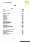
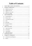
Table of contents
Exhaust system
Exhaust components
Exhaust manifold
Catalytic converter
Muffler
Connecting pipes
Exhaust gas composition
The relevant gases and substances
Effects of stoichiometric ratio
In catalytic converter efficiency
Composition of exhaust gases
Exhaust gas analysis
HC levels
O2 levels
Carbon Monoxide levels
Carbon dioxide levels
Suzuki exhaust symptom diagnosis
4
5
6
6
9
9
10
11
12
13
14
15
15
16
19
20
EN05 Engine Auxiliary System I Starting system
3
Exhaust system
In this lesson, we will study the basic function of the exhaust
system and its components.
Objectives
At the end of this lesson, you will be able to:
•
•
•
•
Describe the function of the exhaust system
Name the basic components making up the exhaust system.
Describe the functions of individual exhaust gas components
Describe the functions of the catalytic converter
EN05 Engine Auxiliary System I Starting system
4
Function
Exhaust system components
The main purpose of the exhaust system is to:
•
Extract exhaust gases from the exhaust manifold and
discharge them off at a suitable place in the vehicle.
•
Reduce/muffle exhaust gas noise produced during the
combustion process of the internal combustion engine.
•
Reduces environmental pollutants in the exhaust gases
The exhaust system is made up of the following components:
(figure 1)
[1] Exhaust manifold
[2] Warm-up three-way catalytic converter
[3] Catalytic converter
[4] Exhaust pipe No.1
[5] Exhaust pipe No.2
[6] Exhaust muffler 1
[7] Exhaust muffler 2
[8] Front muffler
[9] A/F sensor
[10] HO2S
Fresh air
Exhaust gases
Figure 1- Exhaust system components (Suzuki Kizashi)
EN05 Engine Auxiliary System I Starting system
5
Exhaust manifold
Catalytic Converter
The exhaust manifold is mounted directly onto the cylinder
head exhaust side and it is made of pipes that cover the
openings of the exhaust ports on the cylinder head. Its main
function is to extract the exhaust gases and channel them into
the exhaust pipes.
The exhaust system is usually made of cast iron, stainless steel
or light weight steel tubing. A gasket is used between the
cylinder head and the exhaust manifold to prevent leakage.
1
Figure 3 – Catalytic converter
Function
2
Figure 2- Exhaust manifold (1) and catalytic
converter (2)
EN05 Engine Auxiliary System I Starting system
The catalytic converter is an emission control device added to
the exhaust system to lower the levels of Hydrocarbon (HC),
Carbon Monoxide (CO), and Oxides of Nitrogen (NOx)
pollutants in exhaust gases.
A catalyst in the convertor chemically treats pollutants in the
exhaust gases converting them to less harmful substances. A
catalyst causes a chemical reaction but after the reaction it
remains unchanged.
6
Design
Two way catalytic convertors
The catalytic converter has a ceramic core, housed in a
stainless steel shell. The core contains many small passages
through which the exhaust gas pass. A thin coating of
aluminum oxide covers these passages and has a rough
surface and is designed to provide a large surface area in the
passages where the exhaust gasses pass.
The two way catalytic convertor has two simultaneous tasks.
In this process, Oxygen (O2) reacts with Carbon monoxide
(CO) to produce carbon dioxide (CO2). The Oxygen also reacts
with hydrocarbons (un-burnt or partially burnt fuel) to produce
carbon dioxide (CO2) and water (H2O). Two way catalytic
convertors are unable to reduce Nitrogen Oxides.
Three-Way Catalytic converter
Metal core
This is made of finely corrugated 0.05mm thick metal foil,
wound around and brazed in a high temperature process. It
offers extremely low resistance to the flow of the gases.
In addition to the two tasks performed by the Two-way
catalytic converter, the Three-Way Catalytic (TWC) convertor
also uses carbon monoxide (CO) to convert Nitrogen Oxides
(NOx) to Nitrogen (N2) and Carbon dioxide (CO2)
Ceramic core
The ceramic monolith is made of cordierite. It has an extremely
high stability to temperature and thermal shock but cannot be
installed directly to the metal housing. A special expanding
mat is necessary to compensate for the difference between the
thermal-expansion coefficients of steel and ceramic and also
protects the ceramic monolith against shocks.
Catalyst
The catalyst is made of a precious metal. Platinum is widely
used as a catalyst in the catalytic converter. The harmful
exhaust gasses react with the platinum to produce less harmful
gases. Platinum and palladium accelerate the oxidation of HC
and CO, while rhodium is responsible for reducing NOx.
Figure 4 - Function of the TWC
EN05 Engine Auxiliary System I Starting system
7
Operating temperature of the catalytic converter
Catalytic converters do not start significant conversion until
they have reached a specific temperature.
On the TWC’s this is approx. 300ºC. Ideal conditions for high
conversion rates are achieved at 400ºC to 800ºC.
Oxygen sensors
Oxygen sensors are installed up-stream and down-steam of
the catalytic converter and measure the amount of oxygen
content in the exhaust gases. The upstream oxygen sensor
signal is used by the ECM to regulate very precisely the
air/fuel mixture for combustion to the value Lambda = 1. The
downstream oxygen sensor is used by the ECM to determine
the efficiency of the catalytic converter.
figure 5 - Exhaust gas oxygen sensor
Figure 6 - Location of exhaust gas oxygen sensors
[1] Catalytic Converter
[4] Up-stream oxygen sensor (A/F sensor)
[5] Down-stream oxygen sensor (H2OS)
EN05 Engine Auxiliary System I Starting system
8
Muffler
Connecting pipes
Exhaust mufflers smooth out exhaust gas pulsations and make
them as inaudible as possible. There are essentially two
physical principles involved: reflection and absorption.
These are used to connect the exhaust components together
e.g. connecting the catalytic converter tot the muffler. At
some instances, flexible pipes are used to allow engine
movement and reduce vibrations without passing it to the rest
of the exhaust, especially in front wheel drive vehicles. It also
helps with alignment of the pipes.
The complete exhaust system is secured to the vehicle using
brackets and elastic mounting elements.
1
Figure 5 – Exhaust muffler
Figure 6 – Dual exhaust mufflers (Suzuki Kizashi)
[1] Connecting pipe
EN05 Engine Auxiliary System I Starting system
9
Exhaust gas
composition
In this lesson, we will study composition of the exhaust gases
and the exhaust gas analyzer.
Objectives
At the end of this lesson, you will be able to:
• Name the gases that can be found in exhaust gases upstream of the catalytic converter
• Name the gases that can be found in the exhaust system
down-stream of the catalytic convertor
• Describe the effect of the stoichiometric ratio in the
composition of exhaust gases.
• Interpret exhaust gases
EN05 Engine Auxiliary System I Starting system
10
The relevant gases and substances
Carbon Monoxide (CO)
Hydrocarbons (HC)
Nitrogen Oxides (NOx)
Nitrogen dioxide (NO2)
Nitric oxide (NO)
Hydrocarbons (HC)
Oxygen (O2)
Carbon dioxide CO2)
Benzene (A hydrocarbon)
Lead (Pb)
Effects of rich and lean mixtures on exhaust gases
The concentrations of pollutants in the untreated exhaust gas
(upstream of the catalytic converter) largely depend on the
air/fuel ratio. A mixture composition in the stoichiometric
ratio λ = 1 results in exhaust gases that have very low levels
of pollutants. The ideal theoretical stoichiometric ratio is 14:1
(14 parts of air mixed with 1 part of fuel).
Figure 1 – Effects of air/fuel mixture on exhaust gases
[a] Exhaust gases upstream of catalytic converter
[b] Exhaust gases downstream of catalytic converter
[c] Electrical voltage of two step λ sensor
EN05 Engine Auxiliary System I Starting system
11
The perfect combustion
Figure 2 – O2 level against air/fuel ratio
[A] Stoichiometric band
[R] Rich
[W] Weak
EN05 Engine Auxiliary System I Starting system
12
The imperfect combustion
Composition of exhaust gases
Figure 3 – Composition of exhaust gases
Figure 4 – Composition of pollutants in exhaust gases
EN05 Engine Auxiliary System I Starting system
13
Exhaust gas analysis
Diagnosis using exhaust gas analysis
Use of the exhaust gas analyzer can be helpful in
troubleshooting both emissions and drivability concerns
(engine malfunctions).
In troubleshooting, always remember the combustion
chemistry:
Fuel (Hydrogen, carbon, sulfur) + air (Nitrogen, oxygen) =
Carbon dioxide + water vapor + oxygen + carbon monoxide +
hydrocarbon +oxides of nitrogen +sulfur oxides
In any diagnosis of emission or drivability related concerns,
ask yourself the following questions:
• What is the symptom?
• What are the baseline exhaust readings? At idle, 2500 rpm,
acceleration, deceleration, light load cruise, load.
• Which sub-systems or components could cause the
combination of exhaust gas readings measured?
Figure 5 – Exhaust gas analyzer
EN05 Engine Auxiliary System I Starting system
14
Hydrocarbon (HC) levels
Oxygen (O2) Levels
HC is un-burnt fuel that remains as a result of misfire. When
combustion doesn’t take place or only part of the air/fuel
charge burns, hydrocarbon levels go up. The hydrocarbons are
measured by an exhaust analyzer in parts per million (ppm).
The following figures are offered as a guide:
Oxygen is measured by the exhaust gas analyzer in
percentages (%). The amount of oxygen produced by the
engine is affected by how close the air/fuel ratio is to
stoichiometry. As the mixture goes lean, oxygen increases
and it decreases as the mixture goes rich.
Petrol injection
models
Carburetor models
At idle speed
Below 100 ppm
Below 300 ppm
At 3000 rpm
Below 50 ppm
Below 100 ppm
EN05 Engine Auxiliary System I Starting system
The normal readings are below 1.5%
15
Carbon Monoxide (CO) level
Carburetor engines
Carbon Monoxide (CO) level
Carburetor engines (continued)
Carbon monoxide is measured by the exhaust analyzer in % or
parts per hundred. CO is a byproduct of combustion, therefore,
if combustion does not take place, carbon monoxide will not
be created.
EN05 Engine Auxiliary System I Starting system
16
Carbon Monoxide (CO) level
Carburetor engines (continued)
Carbon Monoxide (CO) level
Petrol injected engines
The measure of CO percentage is used to assess the mixture
strength of the vehicle. The lower the CO level the weaker
the mixture and conversely the higher the CO level the richer
the mixture. The CO level can be assessed under three
different operating conditions: Idle, acceleration and cruising.
Idle CO
The CO is measured at the correct idle speed for the vehicle
as specified by the service manual and compared with the
manufacturers recommended figures.
Acceleration CO
This can be measured by snapping open the throttle once and
watching the CO level increase.
Cruising CO
This can be measured by holding the engine at a steady 3000
rpm. The readings should range between 0% and 1%, on
electronic systems and 0% and 2.5% on the K-Jetronic
(Mechanical) system
EN05 Engine Auxiliary System I Starting system
17
Carbon Monoxide (CO) level
Petrol injected engines (continued)
EN05 Engine Auxiliary System I Starting system
Carbon Monoxide (CO) level
Petrol injected engines (continued)
18
Carbon Monoxide (CO) level
Petrol injected engines (continued)
EN05 Engine Auxiliary System I Starting system
Carbon Dioxide (CO2) level
Carbon dioxide is a byproduct of efficient and complete
combustion. Near perfect combustion will result in carbon
dioxide levels which approach the theoretical maximum of
approximately 15.5%. Carbon dioxide levels are affected by
air/fuel ratio, spark timing and any other factors which affect
combustion efficiency. The minimum level should not be
below 10%.
19
Suzuki exhaust emissions symptom diagnosis
Exhaust emissions analysis
The following photo shows the analysis of exhaust gases in a
Suzuki Swift AZH414 with no engine malfunctions.
Figure 6 – Exhaust gas analysis, Suzuki Swift
CO = 0.00%
HC = 0 ppm
CO2 = 12.8%
O2 = 0.07%
λ = 1.003
Air/Fuel Ratio = 15.5
EN05 Engine Auxiliary System I Starting system
20
Summary
• A catalytic converter removes harmful pollutants from the
exhaust gases though chemical reactions.
• Excess oxygen in the exhaust gas results in increase NOx.
• Oxygen reacts with the carbon monoxide and hydrocarbons
to produce water and carbon dioxide.
• The carbon monoxide reacts with NOx to produce nitrogen
and carbon dioxide.
• The exhaust mufflers are used to reduce exhaust noises
generated during the combustion process.
• The upstream oxygen sensor is used by the engine control
module correct the air/fuel mixture.
• The downstream oxygen sensor is used by the engine
control module to monitor the efficiency of the catalyst.
• Exhaust gas analysis can be used to diagnose engine
malfunctions.
EN05 Engine Auxiliary System I Starting system
21
Well done, you have now completed
the “Exhaust system” training course!
Please complete the online exam.
EN05 Engine Auxiliary System I Starting system
22