1
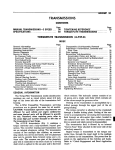
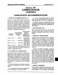
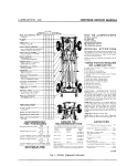
UNIVERSAL JOINTS & PROPELLER SHAFT—1
CHRYSLER SERVICE MANUAL
Section XII
UNIVERSAL JOINTS
AND PROPELLER SHAFT
CONTENTS
Page
Servicing Cross Type Universal owuut
4
Servicing Ball and Trunnion Type Universal Joints
4
Servicing Cross and Yoke Type Propeller Shaft
6
Servicing Propeller Shaft Center Bearing
7
Rear Axle Control Strut.
7
Checking Propeller Shaft Angles
11
Service Diagnosis
11
DATA AND SPECIFICATIONS
Models
Town 8s Country
LC-1
LC-3
LY-1
LC-1, 2
LC-3
1
1
1
1
2
3.0 in.
3.0 in.
3.25 in.
3.25 in.
2.75 in.
3.25 in.
3.25 in.
3.25 in.
3.25 in.
2.75 in.
58.96
58.96
58.96
58.96
63.64
Propeller Shaft
Number Used
Diameter
With TorqueFlite Transmission
Diameter with Air Conditioning
And TorqueFlite Transmission
Length
Centerline to Centerline of "U" Joints
With TorqueFlite Transmission
2—UNIVERSAL JOINTS & PROPELLER SHAFT
CHRYSLER SERVICE MANUAL
ROLLER A N D BUSHING ASSEMBLY
ROLLER AND BUSHING ASSEMBLY
RETAINER
PROPELLER SHAFT
BUSHING RETAINER
CLAMP
RETAINER
CLAMP
LOCKWASHER
ROLLER DUST SEAL
BOLT
DUST SEAL RETAINER
ROLLER A N D BUSHING ASSEMBLY
CROSS ASSEMBLY
ROLLER DUST SEAL
BUSHING RETAINER
DUST SEAL RETAINER
ROLLER AND BUSHING ASSEMBLY
55x767 A
Fig.
1— Rear Universal Joint—Cross Type (Disassembled View)
CENTERING BUTTON
BUTTON SPRING
BALL A N D ROLLERS
GREASE COVER
v
GASKET
PIN
NUT
THRUST WASHER
BODY
PROPELLER SHAFT
BALL A N D ROLLERS
LOCKWASHER
SHAFT BOLT
BUTTON SPRING
CENTERING BUTTON
54x49
Fig. 2—Front Universal Joint—Ball and Trunnion Type (Disassembled View)
CHRYSLER SERVICE MANUAL
UNIVERSAL JOINTS & PROPELLER SHAFT—3
DATA AND SPECIFICATIONS (Cont'd)
Models
Flange to Flange Length
With TorqueFlite Transmission
LC-1,2
LC,3
Town & Country
LC-1
LC-3
LY-1
61.10
61.10
61.10
61.10
64.14
Lubrication
•PRE-PACK
Universal Joints
Type
(Front) Ball and Trunnion
(Rear) Cross Type
Cross Type
(Only)
ANTI-FRICTION
Bushing-Bearing Type
•Every 20,000 miles.
Section XII
UNIVERSAL JOINTS AND
PROPELLER SHAFT
UNIVERSAL JOINTS
Two types of Universal Joints are used on 1958
Chrysler Models and are as follows: The Cross
Type, as shown in Figure 1, and Ball and
Trunnion Type, as shown in Figure 2.
The ball head of the Ball and Trunnion Type,
is an integral part of the tubular propeller
shaft and is covered by the joint body. The
pin, with balls, needle bearings, thrust washers, centering button, and button spring at each
end, extends through the propeller shaft ball
head and rides in ball channels in the body of
the joint assembly. This balanced installation
is designed to absorb thrust and torque of the
drive line. This type of joint is used in Chrysler
Models LC-1, 2 and 3 at front universal joint.
The Cross Type universal joint is used at
rear joint of all models, and front and center
bearing joints of Imperial Models which are
equipped with center bearing and two propeller shafts.
No adjustments are provided to compensate
for wear in universal joint assembly. Parts
that show excessive wear must be replaced.
CAUTION
When disassembling universal joints, keep parts
identified as to original position. Failure to assemble parts in their original positions may
cause an unbalanced condition in the propeller
shaft. Retorque mounting nuts after the initial
1,000 miles of operation.
4—UNIVERSAL JOINTS & PROPELLER SHAFT
CHRYSLER SERVICE MANUAL
CROSS TYPE
1. SERVICING CROSS TYPE UNIVERSAL
JOINTS (Fig. 1)
Remove propeller shaft from the vehicle. Remove two bushing retainers holding bushings
in shaft yoke and remove bushings. Tilt cross
so that it may be removed from propeller shaft
yoke. Straighten out end of retainer lock and
remove two roller and block assemblies. Remove dust seals and retainers. Inspect parts
and replace parts that show wear. Lubricate
roller and bushings with universal joint grease
(extreme pressure) and assemble joint in reverse order of disassembly.
BALL AND TRUNNION TYPE
2. SERVICING BALL AND TRUNNION TYPE
UNIVERSAL JOINT
To disassemble universal joint for repair or
inspection of all component parts, refer to Fig.
2 and proceed as follows: Remove joint body
metal cover and gasket by bending tabs of cover away from body; remove cover and gasket.
Slide body down on propeller shaft exposing
two centering buttons. Remove centering buttons and spring washers from ends of trunnion
pins. Slide two balls, rollers, and thrust washers off trunnion pin. Wash all parts with solvent and blow dry with compressed air. Inspect and replace worn parts.
NOTE: Reconditioning of ball and trunnion
type universal joints will only be necessary when
excessive backlash exists between balls and
trunnion. In some instances, it will be found
that universal joint body has worn, and it will
be necessary to replace all parts, including body
pin, thrust washers, and centering buttons.
Worn rollers should also be replaced.
CAUTION
When installing trunnion pin in propeller shaft
care should be taken to see that trunnion pin
is centered in shaft. Each end of pin should
protrude the same distance, with variation of
no more than .003 inch. If one side of pin extends more than .003 inch farther than the
other, propeller shaft will be out of balance.
Tool C-3534 (LC-1 and 2 models), Tool C-3211
on the LC-3, as shown in Figure 3, will facilitate removal, installation, and centering of
trunnion pin.
Failure to observe these recommendations
may result in an out-of-balance condition causing vibration.
3. UNIVERSAL JOINT MAINTENANCE
(BALL AND TRUNNION)
The universal joints, propeller shaft, and hand
brake drum are accurately balanced during
process of manufacture. Care should be exercised to maintain this condition of balance by
close adherence to the following: Do not use
more than 2% ounces of lubricant in a universal joint (ball and trunnion type) of the LC-3
and 2 ounces in the LC-1 and 2 at any time.
Keep propeller shaft, hand brake drum, flanges,
etc. free from undercoating, dirt and ice.
Fig. 3-lnstalling Joint Pin
CHRYSLER SERVICE MANUAL
UNIVERSAL JOINTS & PROPELLER SHAFT—5
4. SERVICING EXTERNAL TYPE UNIVERSAL
JOINT DUST COVER
UNIVERSAL JOINT
CENTERING PIN
PROPELLER SHAFT
UNIVERSAL JOINT
DUST COVER OR
BOOT
UNIVERSAL JOINT BODY
To replace an external type universal joint dust
cover (Fig. 4) that is damaged, remove propeller shaft assembly from car and clamp
lightly in vise. One end of shaft should be
resting on bench in a horizontal position, disassemble joint, removing all parts except body
and pin. Clean body, ball head, and pin, thoroughly.
A complete coating of grease (or suitable
rubber lubricant) must be smeared on outside
and inside of dust cover, entire surface of ball
head, pin, and inside of body. (It is very important that this instruction be followed.)
Stretch grease-soaked boot or dust cover over
pin and ball head, as shown in Figure 5. Work
dust cover into body as far as possible.
CAUTION
USE NO TOOLS FOR THIS OPERATION.
With body in. position so pin can enter ball
channels, pull body sharply over pin, thereby
forcing dust cover into body. With one hand,
grip end of dust cover, protruding through
back end of body. With other hand, pump
body back and forth, as shown in Figure 6,
until entire dust cover has passed through
body. During operation cone may have reversed
itself inside dust cover. Pull it out to its normal
position.
Insert 2y2 ounces of heavy fiber, universal
joint grease in joint of LC-3 (2 ounces in the
49x910
Fig. 5-Sliding Cover Over Ball Head and Fin
LC-1 and 2) and assemble balls to pin. Install
cover.
Install shaft, using new lockwashers. Be
sure to double check flange bolts for tightness,
to insure against grease leakage. Recheck after
1,000 miles of operation.
CAUTION
Never attempt to use a needle-like arrangement
for forcing lubricant into boot (or dust cover)
on universal joints. Excessive grease can be
forced into boot and cause shaft to be thrown
but of balance, burst boot, or lubricant can be
lost through injection hole during high speed
operation. The joints must be disassembled and
packed with universal joint grease.
55x766
Fig. 4—External Type Dust Cover
Fig. 6 - W o r k i n g Dust Cover Through Body
6—UNIVERSAL JOINTS & PROPELLER SHAFT
CHRYSLER SERVICE MANUAL
CROSS AND YOKE TYPE PROPELLER SHAFT
5. SERVICING CROSS AND YOKE TYPE
PROPELLER SHAFT (Fig. 7)
(Imperial Models)
a. Removal
Remove nuts, lockwashers and bolts holding
universal joint and propeller shaft to differential and transmission companion flanges and
center bearing to frame crossmember. Remove
propeller shaft assembly.
b. Disassembly
Place assembly in bench vise and remove
splined yoke cross bushing retainers. Press out
bushings and remove cross from yoke. Remove
bearing blocks, dust seals, and dust seal retainers. Remove retainers from cross roller bearings. Press out bearings and cross. Remove
dust seals and retainers from cross. The cross
roller bearing block and its component parts,
also form an assembly. These parts are not
serviced separately. After disassembly, clean
and inspect parts and replace those worn or
damaged as necessary.
c. Assembly
Lubricate all parts before assembling. If splined
joint at rear of front propeller shaft has been
disassembled, fill cavity with one ounce (by
weight) of MS 1124. The center bearing is
a sealed bearing and does not require lubrication. Install dust shields and retainers on cross.
Press cross roller bearing and bushing assembly into yoke with cross in proper location.
CAUTION
Make certain that all of roller bearings are correctly placed in roller bushing. Also, be sure
balance arrows are in alignment (Fig. 7 ) .
d. Installation
Place propeller shaft in its correct position under car. Make certain that slip-spline end of
shaft is located toward front of car. Insert attaching screws and tighten securely.
BUSHING
SEAL
.RETAINER
HOUSING
BEARING
SLINGER
SHAFT
SPACER
Fig, 7—Propeller Shaft and Center Bearing Assembly (Disassembled View)
56x320
CHRYSLER SERVICE MANUAL
UNIVERSAL JOINTS & PROPELLER SHAFT—7
6. SERVICING PROPELLER SHAFT CENTER
BEARING (Figure 7)
The center bearing and housing must be removed as a unit, together with front propeller
shaft, for servicing.
CAUTION
Do not extend two piece center bearing pro-
peller shaft to its full length. The seal may be
damaged by the splines on universal joint yoke.
With yoke all the way into front propeller
shaft, bend up tang on dust seal cover. Remove
cover, seal, lock and dust slinger and remove
center bearing assembly. Inspect bearing,
bracket, seal. Replace necessary parts and reassemble.
REAR AXLE CONTROL STRUT
The 1958 Imperials are designed with two
propeller shafts and a propeller shaft center
bearing, as shown in Fig. 8. Conditions may
arise under certain passenger loads which may
create a propeller shaft shudder or vibration
at speeds of 15 to 20 miles per hour.
With fuel tank approximately % full, determine under what speed and passenger load
a shudder is present and if shudder is light,
moderate or heavy. Check the indexing of universal joints and propeller shaft assembly, as
shown in Figure 7. The letter "0" on front
In order to control this shudder or vibration,
a rear axle control strut, as shown in Figure
9, has been incorporated in rear axle design
for purpose of controlling rise of nose of rear
axle carrier under varying load conditions.
Corrections of propeller shaft shudder should
be made as follows: Before diagnosing a shudder condition, make sure engine has been tuned
and is operating smoothly with no hesitation
or stumble on accelerator.
FRAME BRACKET
I HOUSING BRACKET
NOTE: A rough engine can aggravate or produce a shudder.
FRONT PROPELLER
SHAFT ASSEMBLY
57x311
Fig. 9—Rear Axle Control Strut
SEAL NUT LOCK
CENTER BEARING
OIL SLINGER
REAR PROPELLER
SHAFT ASSEMBLY
56x242
Fig. 8—Center Bearing Installed
Fig. 10—Differential Carrier Bumper Plate
8—UNIVERSAL JOINTS & PROPELLER SHAFT
CHRYSLER SERVICE MANUAL
58x702
Fig. 11—Indexing Gauge Installed
Fig. 13—Checking Propeller-Shaft Angle
face of spline should be lined up with key slot
at rear of front shaft.
Place car on platform with weight of vehicle
on rear wheels. With fuel tank between % and
full and weight of vehicle on wheels, remove
differential carrier rebound bumper plate, Figure 10.
tion marks fore or aft, rear axle joint angle
is within specifications and should be considered standard adjustment.
Working from the left side of car, place
and index the aligning gauge Tool J-6845 on
the machine pads of the differential carrier,
as shown in Figure 11.
Adjust bubble of gauge to show zero or level
position. With zero remaining in the level position, remove gauge from differential housing and install gauge along the underside of
rear propeller shaft as shown in Figure 12.
With gauge properly located under shaft
(with level readable from the left side of shaft,
Fig. 12), note the location of the leading edge
of bubble in level gauge; if bubble is still at
zero or level position or within three gradua-
If leading edge of bubble is forward of the
third graduation, the propeller shaft angle
should be corrected by placing a 2 degree taper.ed shim between the rear axle housing pads
and both rear springs with the thick end of
shim towards the front of car.
NOTE: To install shim the rear spring "U"
bolts should be loosened just enough to allow
for installation of tapered shim without misalignment of spring center bolt and housing
pad.
To allow the differential carrier to reposition
itself or assume the new angularity after installation of tapered shims between housing
pad and rear spring, the control strut frame
58x701
Fig. 12—Indexing Gauge Under Shaft
Fig. 14—Gauge Adapter Installed
CHRYSLER SERVICE MANUAL
UNIVERSAL JOINTS & PROPELLER SHAFT—9
to bracket bolts should be loosened to unload
the strut.
Reshim strut bracket after installing tapered
shim between rear axle housing pads and rear
spring.
ADD SHIMS
To check the center propeller shaft angle,
refer to Figure 13 and proceed as follows:
Index the aligning gauge squarely under the
rear propeller shaft and reset level to zero
(Fig. 14).
Install front propeller shaft adapter on front
shaft with pins of adapter pointing towards
the left of car, (Fig. 14). Locate gauge to
adapter on front shaft making sure that locating pins are placed squarely on adapter and
gauge, (Fig. 15).
Note the location of leading edge of bubble
in level. For each graduation the leading edge
of bubble is forward of the center, (Figure 16)
add a shim beneath the center bearing support
bracket.
For each graduation the trailing edge of the
bubble is to the rear of center in level, (Fig.
17) subtract or remove one shim from beneath
center bearing support bracket.
NOTE: Always recheck center joint working
angle, after shimming center joint working
angle.
58x705
Fig. 16—Bubble Location (Forward of Center)
passenger load. Reasonable care must be exercised to obtain accuracy of this measurement.
NOTE: If car is located on a hoist that supports
rear of car on axle housing, the angle of the
universal joints will be influenced.
If measured angle is not 1 to 3 degrees, correction should be made by shimming axle with
2° taper shim. After rear universal joint angle has been adjusted as near to two degrees
as possible, measure middle universal joint
working angle. This working angle should be
1% degrees (more or less) with the apex upward, for rear universal joint angle of two
degrees at zero passenger load.
For other angles, see table below:
TABLE
Rear Joint
1
Middle Joint
1%°
To check propeller shaft alignment with
protractor proceed as follows:
2
Measure rear universal joint working angle.
This angle should be 1 to 3 degrees at zero
3
3%
1°
The middle universal joint angle is adjusted
by adding or removing shims between center
SUBTRACT SHIMS
58x706
58x704
Fig. 15—Indexing Gauge to Adapter
Fig. 17-Bubble Location (Rear of Center)
10—UNIVERSAL JOINTS & PROPELLER SHAFT
CHRYSLER SERVICE MANUAL
MIDDLE JOINT
CENTER
FRONT JOINT CENTER
REAR JOINT CENTER
2°
"*
HORIZONTAL
OR
FLOOR LINE
PINION
SHAFT
CENTER
FRONT SHAFT
REAR SHAFT
57x312
Fig. 18—Determining Working Angles—Front and Rear Propeller Shaft
bearing insulator and crossmember. Adding i/8
inch shim will increase middle universal joint
angle about i/2 degrees; likewise, removing i/8
inch shim will reduce angle about 14 degree.
In measuring the angles of front and rear
propeller shafts and the pinion shaft, a spirit
level protractor must be used to determine
amount the shafts are below horizontal (or the
end of the shaft is pointing down). Determine
working angles, as shown in Figure 18.
Since adjacent shafts are pointing in different directions (up or down) when viewed
in same direction (from front to rear of car)
the working angles are obtained by adding the
angles below horizontal. Therefore, the middle joint working angle as shown in Figure 18,
is 2° and the rear joint working angle is 3°.
If the adjacent shafts were pointing in the
same direction then the angles below horizontal
Fig. 19—Checking Front Propeller Shaft Angles
Fig. 20—Checking Rear Propeller Shaft Angles
would be subtracted to obtain the joint working angle.
If large number of shims must be added or
removed at center bearing, rear universal
joint angle should be rechecked to be assured
that it has not been appreciably altered from
two degrees.
When these adjustments have been made, the
least amount of propeller shaft shudder should
occur at a loading of two passengers. If, after
road testing, it is desirable to obtain the least
amount of propeller shaft shudder at large pas-
Fig. 21—Checking Companion Flange Angle
CHRYSLER SERVICE MANUAL
UNIVERSAL JOINTS & PROPELLER SHAFT—11
senger loading, center bearing must be raised
slightly by means of shimming. Lowering center bearing will move point of least shudder
to a lower passenger loading.
7. CHECKING PROPELLER SHAFT ANGLES
Locate car over pit with wheels supporting car.
Check universal joint angles with a spirit level
protractor, as shown in Figures 19 and 20.
Measure angles of front propeller shaft, middle
propeller shaft, and rear axle pinion drive shaft
flange.
The rear axle drive pinion shaft flange angle
should be obtained by removal of rear end of
rear propeller shaft, and measuring angle of
front face of companion flange, as shown in
Figure 21.
SERVICE DIAGNOSIS
8. PROPELLER SHAFT VIBRATES
a. If propeller shaft, drum and flange are
not shielded while car is being undercoated,
the undercoating material may accumulate on
underside of propeller shaft and cause vibration. To remedy such a condition, inspect shaft
and remove undercoating material (if present)
with solvent.
b. Check transmission flange nuts and rear
axle differential flange nuts for looseness.
Tighten to Data and Specifications.
c. Check alignment of balance arrows on
both shaft and front universal joint. These arrows must be exactly in line. If not, reposition
splines so that arrows are properly aligned.
9. UNIVERSAL IOINTS NOISY
a. Check universal joint for possible dam-
age and tighten propeller shaft flange bolts to
Data and Specifications.
b. Disassemble universal joints and inspect
all parts for wear or damage. Replace parts
as required, pack bearings with universal joint
grease and reassemble.
c. Inspect universal joint bearings for wear
and replace as necessary.
d. Check for flange runout. In many instances, it is possible to correct a flange runout condition by repositioning universal joint
180 degrees with companion flange. Reposition
only one universal joint at a time and road test
car after each repositioning operation.
e. Check splines. If excessively loose, inspect
splines on shaft or in flange for wear or damage. Replace shaft or flange, as necessary, to
correct condition.