1
FRONT WHEEL SUSPENSION—7
CHRYSLER SERVICE MANUAL
Section I
TORSION-AIRE
FRONT W H E E L SUSPENSION
CONTENTS
Page
10
Servicing the Front Wheel Suspension
Checking Front Suspension Height..
12
Front Wheel Alignment
18
Adjusting Front Wheel T o e - i n . . . . . . . . . . . . . . . . . . . . . . . . . . . . . . . . . . 15
Checking Steering Axis Inclination
16
Servicing the Torsion Bars
19
Front Wheel Bearing End Play Adjustment.
Service Diagnosis
. . . .22
22
DATA AND SPECIFICATIONS
MANUAL STEERING
Caster
Camber
Steering Axis
Inclination
— H° ± %°
+ 0°± H° (right)
5° to 7°
+
l
A°±H°
(left)
At 0° Camber
Toe-In
y% ±
w
(Vs" Preferred)
WITH POWER STEERING
Caster
Camber
Steering Axis
Inclination
+ H° ± H°
0° + U° (right)
5° to 7°
+ H° ± H° (left)
At 0° Camber
Toe-In
9
y% ± w
(V/ Preferred)
SPECIAL TOOLS
C-3553
. Remover and Installer—Shock Absorber Lower Bushing
C-3557
Installer—Lower Control Arm Bushing
C-3558
Remover and Installer—Upper Control Arm Bushing
C-3561
C-3564
. . . Wrench—Ball Joint Assembly to Upper and Lower Control Arm
Remover—Ball Joint Stud
8—FRONT WHEEL SUSPENSION
CHRYSLER SERVICE MANUAL
TIGHTENING SPECIFICATIONS
Foot-Pounds
Shock Absorber Upper Mounting Nut
25
Shock Absorber Lower Mounting Nut
40
Sway Eliminator Shaft Link Nuts.
.......
Sway Eliminator Insulator Retainer Nuts
15
25
Upper and Lower Control Arm Ball Joints.
250
Lower Ball Joint Stud Nut.
135
Strut to Lower Control Arm Mounting Bolts
65
Lower Control Arm Strut Bushing Nut
..,
35
Shaft to Lower Control Arm Bushing Retaining Nut ( I n n e r ) . . . . . . . . . . . . . . . . . . . . . . . . . . .
Upper Ball Joint Stud Nut
.
125
.
Lower Control Arm Shaft to Crossmember Mounting Nut
135
200
Upper Control Arm to Support Bracket Mounting Bolt Nuts
55-65
Control Arm Support Bracket to Frame Bolt
70
Steering Knuckle to Brake Support Bolt.
55
Steering Knuckle to Steering Knuckle Arm Nut
50
SHOCK A B S O R B E R
ARM
STRUT
Fig.
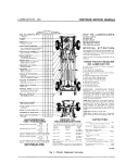
1—Frame a n d Front Suspension
CAR H E I G H T
MANUAL
CHRYSLER SERVICE MANUAL
FRONT WHEEL SUSPENSION—9
SUPPORT BRACKET
BOLT
BOLT
SUPPORT BRACKET
BUSHING
UPPER CONTROL ARM
SHOCK ABSORBER
NUT
WASHER
NUT
BUSHINGx
LOCKWASHER
LOCK RING
SHAFT
LOCKWASHER
NUT
NUT
SWIVEL
LOCK R I N G ' £ | v ,
JOINT—UPPER
sif:.
CAhA
f
SEAT M>
T
BOL
TORSION BAR
NNER
-OUTE
RETAINER
BUMPER
STEERING KNUCKLE
FLAT WASHER
NUT
COTTERPIN
NUT
FLAT WASHER
COTTERPIN
BOLT
-SEAL
LOWER CONTROL ARM
LOCKWASHERS
1
COTTERPIN
I NUT
! RETAINER
WASHER
NUT
COTTERPIN
/BUSHING
1
BALL JOINT—LOWER
LUBE FITTING
STRUT
RETAINER
RETAINER
Fig.
2—Front Suspension (Disassembled View)
Fig. 3—Lower View Front Suspension Assembly
57x70
10—FRONT WHEEL SUSPENSION
CHRYSLER SERVICE MANUAL
Section I
TORSION-AIRE
FRONT W H E E L SUSPENSION
The 1957 Chrysler and Imperial Cars are
equipped with a completely new rubber mounted
ball joint type independent suspension system
using torsion bars instead of coil spring. (Figs.
1, 2, and 3). Torsion bars make more efficient
use of metal, increases the fatigue life of the
metal and permit accurate re-adjustment of
car height to compensate for settling of the
suspension which might occur after long periods of service. This new suspension gives improved steering and directional stability and
with the anti-brake dip principle built into the
design, the tendency of the nose of the car to
dip when braking is reduced to a minimum.
Torsion bar springs also permit relocating of
steering linkage and .control arm inner pivot
points, so that their steering geometries are
more nearly matched resulting in less wheel
fight because the vertical movements of the
road wheels have little effect on the steering
linkage. The new system also offers a number
of other advantages in terms of longer part
life and ease of servicing.
Lubrication
The number of lubrication points has been reduced to 8 in the new suspension system. The
suspension points requiring lubrication are effectively sealed against entry of dust, dirt,
water or other contaminants. Rubber bushings
should not be oiled or greased. The use of lubricant causes pre-mature failure of bushings.
Fig. 4—Upper Control Arm, Shim Pack and Bracket
1. SERVICING THE FRONT
SUSPENSION SYSTEM
The upper control arms are mounted on removable brackets which, are bolted to the frame sub
side-rail. Shim packs are mounted between
brackets and frame side-rail to establish caster
and camber settings for each front wheel, as
shown in Figure 4.
The lower control arms are assembled to
pivot shafts and mounted to frame crossmember in replaceable rubber bushings, as shown
in Figures 5 and 6. The pivot shafts extend
COTTER
PIN
CUSHION
WASHER
H
^
57x63
Fig. 5—Lower Control Arm Pivot Shaft
and Bushing Assembly
TORSION
BAR
'COTTER PIN
LOWER CONTROL ARM
CHRYSLER SERVICE MANUAL
FRONT WHEEL SUSPENSION—11
Fig. 6—Lower Control Arm, Strut
a n d Sway Bar Assembly
through the crossmember and from the axis of
lower control arms. The steering knuckles are
connected, as shown in Figures 7 and 8, to upper and lower arms through ball joints, thus
eliminating the king pins. This also eliminates
the king pin inclination procedures and the
term "Steering Axis Inclination" will be used
hereafter.
To prevent the possibility of any fore and
aft movement of the lower control arms, a strut
is attached from frame crossmember to lower
control arm, as shown in Figure 6. The forward
end of the struts are mounted in the front crossmember with replaceable rubber bushings, as
shown in Figure 9.
The sway bar shaft is insulated and mounted
.1 t > : G K' -CCK'.E
tJ
Fig. 7—Steering Knuckle a n d Ball Joint Assembly
Fig. 9—Front Strut Bar Bushing Assembly
CHRYSLER SERVICE MANUAL
12—FRONT WHEEL SUSPENSION
are marked (L) and (R) in manufacture and
are not interchangeable.
EXHAUST PIPE
CROSSMEMBER
ATTACHING
ADJUSTING C A M
INSULATOR ASSEMBLY
BOLTS
ADJUSTING BOLT
LOWER CONTROL
ARM S T R U T
FRONT SWAY BAR SHAFT
BUSHING ASSEMBLY-
SWAY BAR S H A F T
Fig. 10—Front S w a y Bar to Frame Attachment
r
r"
ENGINE R E A R
C R O S S MEMBER
Jf
/
/
/ / / '
„;
/'/'RIGHT
/FRAME
"
Fig. 11—Torsion
HAND
CROSSMEMBER
ADJUSTING
ANCHOR 3 R A C K E T
E?ACKE~
SIDE T O R S . O N
Ba.;
C2CSS.V.EM3ER
'CROSSMEMBER
•TORSION B A R
ANCHOR
l o c ; ?:\'G
ATTACHING
ATTACHING
BOLT
„
K
BOLT
BOLTS
k
ADJUSTING C A M
I'
/
FRAME
5 7 x 1 9 6
.
CROSSMEMBER
Bar Spring C a m a n d Height
Adjustment Bolt Assembly
to frame and the lower control arm. (Figs. 6
and 10.)
The front end of the torsion bars are indexed
with lower control arms at frame front crossmember pivot points (Figs. 1 and 2). The rear
end of torsion bars are indexed in anchors
which are supported by brackets welded to
frame side-rails and crossmember, as shown in
Figure 11. The torsion bar springs (Fig. 12)
A N C H O R BRACKET
j
LOCK R I N G
.EFT
HAND
SIDE T O R S I O N
CROSSMEMBER
\
BAR
ATTACHING
BOLT
57x78
Fig. 12—Torsion Bar Spring (Rear Mounting)
SERVICE PROCEDURES
2. CHECKING FRONT SUSPENSION HEIGHT
Front suspension height should be checked and
if necessary, reset whenever service work has
been done on the torsion bars. The vehicle
should be placed on a level floor with weight of
vehicle on the torsion bars. (No passenger load,
full gas tank). Using a steel rule, measure from
the lowest point of the ball joint to floor, as
shown in Figure 13. Again using steel rule,
measure from the underside of lower control
arm bushing housing, (at center line of lower
control arm), as shown in Figure 14. Under
car weight, the bushing housing will always be
higher than the ball joint housing. The difference between these two points should be held to
2%e inches plus or minus % inches. Check
measurements on the opposite side of car in
same manner. After the differential measurements have been established for each side, they
should be compared. The results must be held
within % inch of each other.
6
N O T E : Jounce front of car and allow it to find
its free height before checking.
CHRYSLER SERVICE MANUAL
FRONT WHEEL SUSPENSION—13
Fig. 15—Adjusting Torsion Bar C a m Bolt
Fig. 13—Measuring Front Spring Height
Make correction by tightening or loosening
the adjusting bolt at torsion bar anchor, (Fig.
15) until correct height has been obtained.
When front suspension height has been changed
by adjustment, check alignment of front wheels,
and aiming of headlight beam. Adjust as necessary.
3. FRONT WHEEL ALIGNMENT (CASTER
AND CAMBER)
Correct front wheel alignment produces easy,
positive steering with a minimum of scuffing
action between tire and load. Normally, when
checking front wheel alignment, car should be
empty (all luggage or load should be removed).
I f a constant load is carried, such as when a
car is used by salesman for carrying samples,
etc., car should be loaded with its normal
amount of weight before checking front wheel
alignment.
All factors of front wheel alignment are interrelated, but each angle has specific purpose.
Four different angles are used in positioning
front wheels for proper steering under varying
conditions of weight and speed. When making
adjustments or installing new suspension parts,
the alignment angles in both front wheels
should be checked in the following order: Camber, Caster, Steering Axis Inclination and Toe.
H I
4 4L
— NEGATIVE CASTER
FRONT
Ar POSITIVE CASTER
Fig. 14—Measuring Front Spring Height
at Control Arm
Fig. 16— Caster Angle
CH1YSLEH SE1VICE MANUAL
14—FRONT WHEEL SUSPENSION
Fig. 17—Camber Angle Axis Inclination
54x249
NOTE: Front suspension parts are heat treated,
if they are damaged or bent, they should be
replaced. Under no circumstances should these
parts be heated in order to straighten.
Before checking front wheel alignment, the
following inspections should be made to determine the necessity for repair or replacement
of parts.
Inflate all tires to recommended pressure.
Check adjustment of front wheel bearings. (Refer to "Servicing the Steering Knuckles" Paragraph 8, of this Section.) Check tire wear as
outlined in "Wheels and Tires" Section X I I I .
Check upper and lower ball joints, tie rod
ends and idler arm for excessive looseness.
Check for bent frame and rear spring " U "
bolts for tightness or shifted axle housing.
S E C O N D A R Y SCREW
Fig. 19—Checking Camber (Tool C-3409)
Grasp the front and rear bumper at center
and jounce car up and down several times. This
will place the torsion bar springs and shock
absorbers in their "normal" unloaded position.
The car must remain in the "normal unloaded
position" while checking camber, caster and
steering axis inclination.
Negative Caster is amount in degrees that the
axis of the ball joint leans from vertical toward
front of car (Fig. 16).
Positive Caster is the amount of degrees that
ball joints lean toward rear of car.
Camber is amount that front wheels lean outward or inward from the vertical, when viewed
from front of car (Fig. 17). With positive cam-
PRIMARY S C R E W
/
/
'^ x.25C
Fig. 18—Checking Caster—Right Wheel
:
Fig. 20—Removing Shims to Adjust Camber or Caster
FRONT WHEEL SUSPENSION—15
CHRYSLER SERVICE MANUAL
ber, wheels are farther apart at top than at
bottom. With negative camber, this condition
is reversed.
Caster and camber adjustment (Figs. 18 and
19) is accomplished by the use of y and %
inch shims placed between, the upper control
arm support brackets and the frame sub siderails. (Refer to Fig. 20). Shim may be changed
at either front or rear bracket to change the
caster setting or equally at both brackets to
change camber.
16
2
The removal of shims at the rear bracket or
addition of shims to front bracket will decrease
positive caster. One shim (y inch) will change
caster approximately % ° . The addition of
shims at both front and rear support brackets
will decrease positive camber. One shim ( %
inch) at each bracket will change camber (approximately) 1/8°- Caster and camber adjustments are made as follows:
16
6
Remove load from upper control arms and
frame bracket by placing a jack under lower
control arm as near to the front wheel as possible. Raise car off floor. Loosen upper control
arm support bracket bolts and add or remove
shims as required, as shown in Figure 20. Retighten bolts, remove jack and bounce front of
vehicle to allow car to assume its normal operating position before checking wheel alignment.
The total thickness of the shim pack at either
of the support brackets should NOT exceed %
inch.
6
Fig.
22—Steering Geometry on Turns
at front than they are at rear. To measure, spin
front wheels and scribe a thin line in center of
tread of each tire (Fig. 21). Jounce front end
up and down several times and position wheels
in straight-ahead position. Gauge and scriber
Tool C-695 can be used for scribing tire treads
and measuring toe.
Measure distance at hub height between
points A and B, Fig. 21. The distance between
point B should be Vs inch less than distance between point A. To adjust toe, lengthen or short-
4. ADJUSTING FRONT WHEEL TOE-IN
Toe-In means that wheels are closer together
f FRONT |
MARK TIRES HERE
Fig.
21—Front W h e e l Toe-in
Fig.
2 3 - G a u g e C-3409 a n d Turntable DD 4 3 5
on
Right W h e e l
CHRYSLER SERVICE MANUAL
16—FRONT WHEEL SUSPENSION
en the tie rods an equal amount until the
wheels toe-in i/g inch, plus or minus % inch
(I/a inch preferred) and recheck measurements
at points A and B.
2
NOTE: The steering wheel hub, steering gear
arm, steering tube and steering gear roller
shaft are machined with master serrations to
place front wheels straight-ahead when steering
wheel is i n center position. Do not alter these
serrations to change position of these parts.
Improper position of steering wheel must be
corrected by adjusting tie rod lengths.
Toe-out turns.
When car makes a turn, front wheels travel
in circles which have a common center (Fig.
22). The arc of circle traveled by the inside
front wheel is smaller than arc of circle traveled
by outside front wheel. Consequently, when
turned to right or left, the wheels will be farther apart at front than at rear. The amount
that front wheels toe-out depends upon how far
they are turned.
Fig.
24—Checking Steering Axis Inclination
(Gauge
C-3409)
20 degrees then return to 20 degrees. Adjust
secondary screw (Fig. 24). which controls the
short pointer until bubble is centered in spirit
level. Do not disturb gauge setting or release
brakes.
With front wheels on turntables, set right
wheel to 20 degrees. The turntable under left
wheel should indicate 211/2 degrees, plus or minus 1 degree. I f reading is not within these
limits, the steering knuckle arm or steering gear
arm may be bent. Before above check is made,
make sure that camber, caster, steering axis
inclination and toe-in are within limits.
Turn front wheels to right until right wheel
is turned to an angle of more than 20 degrees
mark. Allow wheel to back off to exactly 20 degrees. Adjust primary screw (Fig. 24) until
bubble centers in spirit level. The reading on
40-degree scale of gauge will be steering axis
inclination for right wheel.
5. CHECKING STEERING AXIS INCLINATION
To check angle of left front wheel, place
gauge on left wheel, turn front wheels to right
and repeat procedure outlined above.
Steering axis inclination is amount in degrees
that axis of the ball joints lean away from vertical toward center of car (Fig. 16). I f camber
can be adjusted within the recommended limits,
it is unnecessary to check steering axis inclination.
NOTE: I f the steering
conform with limits
check for bent frame,
t r o l arms or damaged
To check axis inclination refer to Figs. 16
and 17 and proceed as follows:
Inflate tires to recommended pressure, place
front wheels in straight-ahead position on turntables and set foot brakes. Grasp front bumper
at center and move front end of car up and
down several times to permit front suspension
parts to settle in "normal" unloaded position.
Assemble gauge to right wheel (Fig. 23) and
pull out turntable lock pins. Turn front wheels
to left until right wheel has turned more than
axis inclination does not
listed i n Specifications,
steering knuckle or conball joints.
6. SERVICING THE SWAY BAR
(FIGS. 6 and 10)
a. Removal
The front sway bar is attached to frame and
strut bars through insulated rubber mounting
brackets. To remove the sway bar proceed as
follows:
Remove two sway bar link retaining nuts and
concave washers. Remove two sway bar cushion
retaining nuts, lockwashers and bolts, (one on
each strut). Slide sway bar out through con-
CHRYSLER SERVICE MANUAL
trol arm struts and away from vehicle. The
sway bar cushions are not serviced separately.
If replacement is necessary, install new sway bar
assembly.
Remove lower concave washers. Remove
sway bar link insulating- bushings from frame
bracket by forcing out of position. I f bushings
are worn or deteriorated, install new ones as
required.
b. Installation
Dip new sway bar link bushing in water, install in opening in frame bracket, using a twisting motion. When installed properly, the groove
in bushing will index with opening in frame
bracket.
Thread sway bar into position over top of
lower control arm struts. Engage sway bar
cushion housings with struts and install lockplates. Insert bolts, lockwashers and nuts.
Tighten to 25 foot-pounds torque. Install washers over ends of links (concave side up), then
slide links up through bushings. Install washers (concave side down), over ends of links and
down on bushings. Install nuts and tighten to
15 foot-pounds torque.
7. SERVICING THE LOWER CONTROL A R M
STRUT (FIGS. 6 and 9)
a. Removal
Remove the nuts, lockwashers, and bolts that
attach the sway bar bushing housing to struts.
Disconnect sway bar from struts. Remove the
FRONT WHEEL SUSPENSION—17
strut to lower control arm mounting bolts and
nuts. Remove the cotterpin, nut and bushing retainer from forward end of strut at front crossmember. Slide strut and inner bushing retainer
from bushing in frame, as shown in Figure 9.
Using a knife, cut bushing out front of frame.
b. Installation
Dip new bushing in water and with tapered
portion toward rear of vehicle, install in opening in frame using a twisting motion until
groove in bushing indexes properly with frame.
With cupped side out, slide washer over
threaded end of strut. Push strut through
bushing in frame (Fig. 9). Slide outer washer
over end of strut (cupped side i n ) . Install nut.
Tighten nut sufficiently to install strut to lower
control arm mounting bolts. Install bolts, lockwashers and nuts, and tighten to 65 foot-pounds
torque. Tighten strut nut to 30 foot-pounds
torque and install cotter pin. Check caster and
camber.
8. SERVICING THE STEERING KNUCKLES
(FIG. 25)
a. Removal
Remove wheel, tire and drum. Cover brakes
with clean cloth to protect lining from becoming covered with grease. Remove the cotterpins,
nuts and lockwashers attaching the steering
arm and brake dust shield to steering knuckle.
Remove steering arm, and brake assembly from
steering knuckle but leaving the brake hose
attached. Do not allow assembly to hang
by the brake hose. Remove ball joint studs from
steering knuckles as described in "Servicing the
Upper and Lower Ball Joints," Paragraph 9,
using Tool C-3564. Lift steering knuckle out
and away from vehicle.
b. Installation
To install steering knuckle, refer to Fig. 25,
and slide upper and lower ball joint studs into
steering knuckle and install lockwashers and
nuts. Tighten the ball joint stud nut to 135 footpounds torque. Install cotterpins.
.57x368
Fig. 25—Removing or Installing Steering Knuckle
Slide brake assembly over knuckle and into
position. Install lockwashers and nuts on upper
rear and lower front bolts. Install upper front
and lower rear bolts through dust shield and
steering knuckle, then slide steering arm over
18—FRONT WHEEL SUSPENSION
CH1YSLE1 SERVICE MANUAL
bolts. Install lockwashers and nuts. Tighten
nuts evenly to 55 foot-pounds torque. Install
cotterpins. Remove covering from brake shoes,
replace wheel, tire and drum assembly. Adjust
front wheel bearings as per "Front Wheel Bearing End Play Adjustment", Paragraph 16. Refer to "Front Wheel Alignment (Caster and
Camber)", Paragraph 3.
9. SERVICING THE BALL IOINTS—(UPPER
AND LOWER) (FIGS. 28 and 27)
a. Removal of Upper Ball Joint
CAUTION
Upper and lower ball joints are not interchangeable. The upper ball joint is a preloaded joint
and should not be used i n the lower control arm.
Remove wheel and tire assembly. With support
under the lower control arm, remove upper and
lower ball joint stud nuts. Install Tool C-3564
(Fig. 26). Apply load to studs and rap knuckles
at ball joint boss sharply with a hammer to
Fig. 27—Removing or Installing Upper Control Arm
Ball Joints
very important that the ball joint threads engage those of the control a r m squarely.
b. Installation oi Upper Ball Joint
With the lubrication fitting removed, screw ball
joint into control arm as far as possible by
hand. Using Tool C-3461, tighten until ball
joint housing is seated on control arm. Tighten
to a minimum of 250 foot-pounds torque. Slide
seal and dust cover up into position, over stud
and position stud in steering knuckle. Install
washer and nut. Tighten 135 foot-pounds
torque. Install cotter pin and lubrication fitting.
Lubricate ball joint with a good grade of chassis lubricant.
NOTE; When installing new ball joint, i t is
c. Removal of Lower Ball Joint
loosen stud. To avoid damaging stud do not attempt to hammer stud out of knuckle.
Remove tool, and disengage ball joint from
knuckle. Remove ball joint dust cover and
grease seal. Remove lubrication fitting from
top of ball joint, using Tool C-356, as shown
in Figure 27, unscrew ball joint from upper
control arm.
Raise wheel off floor supporting weight under
Fig. 26—Removing Upper Ball Joint—
(Removal Tool C-3564)
Fig. 28—Removing Lower Ball Joint
CHRYSLER SERVICE MANUAL
the lower control arm, allowing enough clearance to remove lower ball joint, and remove
wheel and tire assembly. Remove upper and
lower ball joint stud nuts, install Tool C-3564
(Fig. 28) as described in "Upper Rail Joint
Removal" Paragraph 9 procedure. Rap knuckle
at stud boss sharply with a hammer to loosen
stud. To avoid damaging stud do not attempt to
FRONT WHEEL SUSPENSION—19
Remove the lock ring from rear of anchor
(Fig. 12). Slide torsion bar rearward enough
to disengage forward end of bar from lower
control arm, then forward to disengage torsion
bar from cam. Remove bar, bolt, swivel and
cam from frame bracket anchor.
hammer stud out of knuckle. Remove grease
b. Installation
fitting using Tool C-3561, screw out ball joint.
With car raised off the floor, assemble cam,
swivel, bolt-seat (oval side up) and bolt in
frame anchor bracket. Check for torsion bar
cushion in lower control arm housing, with
cam bolt barely entered in cam swivel. Slide
torsion bar into rear cam. Rotate cam and torsion bar assembly until cam is positioned as
close as possible to floor pan. Engage front of
torsion bar in lower control arm shaft assembly as far as bar will go.
NOTE: When installing new ball joint, i t is very
important that the ball joint threads engage
those of the control arm squarely.
d. Installation of Lower Ball Joint
To reinstall, screw ball joint into control arm
as far as possible by hand. Using Tool C-3561,
tighten until ball joint housing is seated on control arm. Tighten to minimum of 250 footpounds torque. Slide seal and dust cover down
into position, over stud then position stud in
steering knuckle. Install washer and nut. Tighten 135 foot-pounds torque. Install cotterpin;
lubrication fitting and lubricate ball joint, using a good grade of chassis lubricant and reinstall wheel and tire assembly.
10. SERVICING THE TORSION BARS
The torsion bars are not interchangeable, side
for side. The left hand bar cannot be used on
the right side and vice versa. The bars will be
marked left or right by (L) or (R) stamped
on the end of the rod, as shown in Figure 12.
The bars should always be installed with letters
toward the rear of car.
a. Removal of Torsion Bar, Cam Swivel
and Bolt
To replace torsion bar cam, refer to Fig. 2 and
proceed as follows: Raise vehicle off floor by
jacking under frame crossmember. Release load
from torsion bar by unscrewing the cam adjusting bolt partly out of swivel.
CAUTION
To prevent swivel f r o m falling into frame bracket, do not loosen the swivel bolt all the way out
u n t i l torsion bar is removed.
CAUTION
Unless anchor blade is i n the position just described when installing torsion bar, it will be
impossible to adjust front suspension to the
proper suspension height.
Center and install lock ring in rear of cam
housing. Pressure may have to be applied to
torsion bar to enable lock ring to be installed
in housing. After installation of lock ring,
tighten cam bolt until approximately 1 inch of
threads are showing above the anchor bolt
swivel.
N O T E : This is an approximate setting and is
to be used merely as a starting point when adjusting suspension height. This setting is also
necessary to place load on the torsion bar spring
before lowering vehicle to the floor.
Check and adjust suspension height. Refer to
"Checking Front Suspension Height", Paragraph 2.
CAUTION
Caster and camber and front suspension height
should always be checked whenever the torsion
bars are replaced.
Refer to "Checking Front Spring Height",
Paragraph 2 of this section.
20—FRONT WHEEL SUSPENSION
CHRYSLER SERVICE MANUAL
11. SERVICING THE UPPER CONTROL ARM
a. Removal (FIG. 2)
Place a jack under lower control arm and raise
front wheel off floor. Remove wheel and tire
assembly. Remove cotter pin, nut, and washer
from upper ball joint stud. Install tool and load
studs. Using a hammer, remove ball joint stud
from steering knuckle by striking the ball joint
boss on knuckle sharply. Do not hammer on
threaded section of stud.
Remove upper control arm front and rear
pivot bolt. Remove control arm from support
mountings. Do not remove brackets from frame.
b. Installation
Position upper control arm in support mounting
bracket and install front and rear mounting
bolts, washers, and nuts. With control arm in
normal position tighten nuts to 65 foot-pounds
torque. Place upper ball joint stud in steering
knuckle and install washer and nut. Tighten
nut to 135 foot-pounds torque and secure with
cotterpin.
12. UPPER CONTROL ARM B U S H I N G REPLACEMENT
Remove upper control arm. Refer to "Upper
Control Arm—Removal", operations 1 through
7.
Remove bushings by either pressing them out
with Tool C-3558 (Fig. 29) or using a hammer
and suitable drift.
Fig. 30—Installing Upper Control Arm Bushing
N O T E : Make definitely sure control arm is
properly supported when removing bushings.
If hammer and drift are used, extreme care
must be exercised to avoid damaging bushing
surface in the control arm.
When installing new bushings, always make
sure control arm is supported squarely at the
point bushing is being pressed in. Position
flange end of new bushing in Tool C-3558 (Fig.
30), and support control arm squarely. Using
an arbor press, install bushings (flange out)
into control arm until the flanged portion of
bushings seat on arm.
Install upper control arm. Refer to "Control
Arm—Installation", operations 1 through 3.
13. LOWER CONTROL ARM
a. Removal
57x77
k
Fig. 29—Removing Upper Control Arm Bushing
Raise car by placing jack under frame crossmember. Remove wheel and tire assembly. Remove torsion bar spring from lower control arm
to be removed. Refer to "Servicing Torsion Bar
—Removal", Paragraph 10. Remove shock absorber lower eye attachment nut and bolt from
mounting bracket. Push lower portion of shock
absorber up into frame opening. Remove the
two strut to lower control arm mounting bolts
and nuts. Remove cotter pin, nut, and washer
from lower ball joint stud. Remove lower ball
joint stud from knuckle (Refer to Paragraph
9 (a). Remove cotter pin, nut and washer from
lower control arm shaft assembly. With washer
CHRYSLER SERVICE MANUAL
FRONT WHEEL SUSPENSION—21
SHAFT AND
BUSHING
-
z
LOWER
\
CONTROL \
ARM
\
Fig. 31—Removing or Installing Lower Control Arm
Pivot Shaft Bushing
removed, reinstall nut( to protect threads) unt i l i t is flush with end of shaft. The lower control arm shaft is a tapered fit in front crossmember. Use a hammer and brass drift for
loosening, then remove nut from shaft. Slide
lower control arm and shaft assembly from
rear of crossmember.
CAUTION
Do not lose torsion bar spring cushion (small
disc located in end of shaft assembly).
b. Installation
Position shaft and lower arm assembly in
crossmember in normal position; and install
washer and nut. Tighten 175 to 200 foot-pounds
torque and secure with cotter pin. Position
lower ball joint stud in steering knuckle and
install washer and nut. Tighten nut 135 footpounds torque and secure with cotter pin. Place
shock absorber in position in lower mounting
bracket and install bolt and nut. Tighten to 40
foot-pounds torque. Install wheel and tire assembly. Do not lower front of vehicle at this
time. Install torsion bar spring. Refer to "Servicing Torsion Bar Installation", Paragraph 10.
I
t
1
\
!
T
° O
L
XI
Fig. 32-lnstalling Lower Control Arm Pivot Bushing
b. Assembly
Position new bushing (flanged end of bushing
first) on shaft and install washer and nut.
Tighten nut 100 to 150 foot-pounds torque and
install cotter pin.
With lower control arm supported, install
shaft and bushing assembly by using Tool C3557 and pressing bushing into the lower control arm until flanged portion of bushing is
seated all the way into control arm. Install lock
ring making sure i t is seated properly in the
ring groove. Install torsion bar spring cushion
in control arm. Install lower control arm. Refer
to "Lower Control Arm—Installation", Paragraph 13.
15. UPPER CONTROL ARM SUPPORT
MOUNTING BRACKETS
Remove lower control arm assembly. Refer to
"Lower Control Arm—Removal", Paragraph
13. Remove torsion bar spring cushion (small
disc) from end of shaft assembly.
The upper control arm support mounting brackets are bolted to the frame side-rails and should
not be removed unless they have been damaged
due to accident, etc. When removing the mounting brackets, extreme care should be taken so
not to lose the alignment shim pack located
between the bracket and frame side-rail. I n
event a shim pack is lost, a selection of shims
a. Disassembly
when* reassembling.
14. LOWER CONTROL ARM PIVOT SHAFT
BUSHING—REPLACEMENT (FIGS. 31 and 32)
Remove lock ring from end of bushing housing.
Support lower control arm assembly i n an arbor press; and using a brass drift, press shaft
and bushing assembly from control arm. Remove cotter pin, nut, and washer; and slide
bushing assembly from shaft.
Y
16
inch thick may be used as a starting point
16. FRONT WHEEL BEARING END
PLAY ADIUSTMENT
A new front wheel bearing adjusting nut and
lock is used on the 1957 cars to provide greater
22—FRONT WHEEL SUSPENSION
GREASE CAP
THRUST WASHER
NUT LOCK
COTTERPIN
STEERING KNUCKLE
I J/1
BEARING CUP
BEARING CONE
BEARING CONE
57x309
Fig. 33—Front W h e e l Bearing Adjustment
front wheel bearing adjustment accuracy. (Fig.
33).
CHRYSLER SE1VICE MANUAL
To adjust the front wheel bearings, proceed
as follows: Remove any burrs or nicks on the
spindle thread to insure accurate torque readings. Tighten the wheel bearing adjusting nut
with an inch-pound torque wrench to SO inchpounds torque while rotating the wheel.
Selectively position the nut lock over the adjusting nut so that the spindle cotter pin hole
is in line with one set of slots in nut lock. Without removing the nut lock, back off the nut until the next set of slots in nut lock is lined up
with spindle cotter pin hole. Insert and bend
the cotter pin to secure the nut lock.
N O T E : This procedure should result i n f r o m
.000 inch (no pre-load) to .003 inch bearing
free play measured axially.
SERVICE DIAGNOSIS
17. FRONT END NOISY—POSSIBLE CAUSES
AND CORRECTIONS
Shock absorber inoperative—Replace as required.
Lack of lubrication in ball joints or tie rod ends.
Loose sway eliminator—Tighten mounting
bolts to proper torque.
Worn upper or lower control arm pivot bushings (rubber) or loose mounting brackets—
Tighten brackets or replace bushings.
Loose or worn strut mounting bushings (rubber)—Tighten mounting nut to proper torque
or replace bushing.
Worn ball joints or tie rod ends—Replace as
necessary.
Front shock absorber noisy—Tighten mounting nuts or replace bushing or shock absorber
as required.
Sway eliminator noisy—Check attaching
bolts for tightness and rubber bushings for
wear. I f rubber bushings are worn, replace
sway eliminator assembly.
Worn or loose front wheel bearings—Adjust
or replace as required.
18. BODY HAS TENDENCY TO PITCH
AND ROLL
Low or uneven tire pressures—Inflate tires to
proper pressure.
Improper front suspension height—Adjust
torsion bar springs as required.
19. TIRE WEAR
The same items which caused excessive tire
wear in. the previous suspension will also apply
to the 1957 series suspension.
20. STEERING
The following is a list of steering problems
which may be checked after i t has definitely
been established that difficulty is caused by the
front suspension system.
21. WHEEL BOUNCE
Unequal tire pressure—Inflate tires to recommended pressure.
Unbalanced wheels tires or brake drums—A
wheel and tire assembly that is out of static
balance can cause an up and down action which
will affect steering ability and control.
FRONT WHEEL SUSPENSION—23
CH1YSLE1 SERVICE MANUAL
Damaged or in some instances, repaired tires.
Inoperative shock absorber—Replace shock
absorber.
Inoperative shock absorber—Replace as required.
Worn ball joints or tie rod ends—Replace as
required.
22. HARD STEERING
Lack of lubrication in ball joints or tie rod ends.
Low or uneven tire pressure—inflate to proper pressure.
Improper caster—Check and adjust front end
alignment.
Upper or lower control arms bent or twisted
—Replace as required.
Frame bent—Straighten frame and check
alignment.
Bent steering knuckle—Replace as required.
Worn upper or lower control arm bushings—
Replace as required.
Loose or worn strut mounting bushings—
Tighten to proper torque or replace bushings.
Incorrect front end alignment—Check and
adjust front end alignment.
Loose or bent steering knuckle—Tighten or
replace.
Wheels and tires out of balance—Balance
wheels and tires.
23. EXCESSIVE PLAY OR LOOSENESS IN
STEERING SYSTEM
Excessive wheel and tire runout—Correct as
necessary.
Loose stabilizer—Tighten bolts
torque.
25. CAR PULLS TO ONE SIDE
to
proper
Worn or loose front wheel bearings—Replace or adjust as required.
Worn ball joints—Replace as required.
Worn upper or lower control arm bushings—
Replace as required.
Worn tie rod ends—Replace as required.
Low or uneven tire pressure inflate to proper
pressure.
Rear wheels are not tracking with front
wheels—Check alignment to determine cause
and correct as necessary.
Brake dragging—Adjust brakes.
24. FRONT WHEEL SHIMMY
Inoperative shock absorber—Replace as required.
Uneven tire pressure—Inflate to proper pressure.
Incorrect front wheel alignment—Check caster, camber, and toe-in and adjust as required.
Worn or loose front wheel bearings—Replace
or adjust as required.
Bent upper or lower control arm—Replace as
required.
24—REAR AXLE
CHRYSLER SERVICE MANUAL
Section II
REAR A X L E
CONTENTS
Page
Removal of Differential Carrier A s s e m b l y . . . . . . . . . . . . . . . . . . . . . . . . 28
Differential Drive Gear and Cage Disassembly
29
Drive Pinion Shaft and Bearing Disassembly.
.30
Pinion Bearing Pre-Load and Pinion S e t t i n g . . . . . .
..34
Gear Adjustment for Correct Tooth C o n t a c t . . . . . . . . . . . . . . . . . . . . . . 3 9
Axle Assembly
40
Setting Axle Shaft End Play.
.42
Removing Broken Axle Drive Shaft
43
Rear Axle Housing A l i g n m e n t . . . . . . . . . . . . . . . . . . . . . . . . . . . . . . . . . . 43
Service Diagnosis
44
DATA AND SPECIFICATIONS
C-?5
C-76
IM-1-2-4
Type.
Gear Type
Ring Gear Diameter
Semi-Floating
Hypoid
8.75 '
Semi-Floating
Hypoid
8.75"
Semi-Floating
Hypoid
8.75*
Pinion Bearing
Type
Adjustment
2
Tapered Roller
Shim Pack
2
Tapered Roller
Shim Pack
2
Tapered Roller
Shim Pack
2
Tapered Roller
Threaded Adjuster
2
Tapered Roller
Threaded Adjuster
2
Tapered Roller
Threaded Adjuster
Rear Axle
Differential Bearings
Type.
f