1
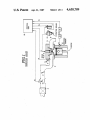
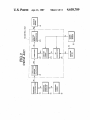
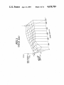
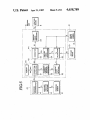
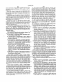
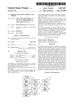
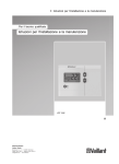
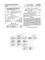
United States Patent [191
Morita
[54] IGNITION TIMING CONTROL SYSTEM
3309947
COMBUSTION ENGINE
7/1984 Fed. Rep. of Germany .... .. 123/422
58-217775 12/1983
59-168266
Tatsuo Morita, Yokosuka, Japan
Japan .................. ..
123/425
9/1984 Japan ................................. .. 123/422
OTHER PUBLICATIONS
“VG-Series Engine Service Manual 1983” Jun. 1983,
by Nissan Motor Company, Limited.
Primary Examiner-Andrew M. Dolinar
Attorney, Agent, or Firm-Schwartz, Jeffery, Schwaab,
Mack, Blumenthal & Evans
[73] Assignee: Nissan Motor Company, Limited,
Yokohama, Japan
[21] Appl. No.: 809,733
Dec. 17, 1985
[22] Filed:
[30]
Foreign Application Priority Data
Jan. 31, 1985 [JP]
Jan. 31, 1985 [JP]
Apr. 21, 1987
FOREIGN PATENT DOCUMENTS
AND METHOD FOR AN INTERNAL
[75] Inventor:
4,658,789
Patent Number:
Date of Patent:
[11]
[45]
[57]
Japan ................................ .. 60-18058
Japan ................................ .. 60-18059
[51]
[52]
Int. Cl.4 .............................. .. F02P 5/145
US. Cl. ........................ .. 123/422; 123/425
[58]
Field of Search ............. .. 123/415, 416, 417, 422,
ABSTRACT
A system and method for controlling the ignition timing
of an internal combustion engine, in which a predeter
mined transient state which increase the probability of
engine knocking is detected, a basic ignition advance
angle value determined by an engine operating condi—
tion is corrected by a retardation angle value which is
123/423, 425
stored when knocking is suppressed during the prede
[56]
References Cited
U.S. PATENT DOCUMENTS
4,428,343
4,448,163
termined transient state and is returned quickly toward
the basic advance angle while ensuring that engine
knocking will not recur after the predetermined tran
1/ 1984 Schweikert et a1. .............. .. 123/425
5/1984 Yoshida ..................... .. 123/422
4,508,079
4/ 1985 Komurasaki et a1. .
4,513,716
4/1985
123/422
I’
—
_
_ _ _
_
_
—
‘_‘|
I
I
,
\.
’——~'——-—-I
-
. KNOCKING
l5“
‘ DISCRIMINATOR [
34
i
l
,
I
|
I
SAk SAm
'
CORRECTION
Vn
,
Tn
TRANSIENT
.
l
:
|
l
I
‘
: regret
:
DETECTOR l
I.‘ ___
Ve
33
xuocxms
SENSOR
LP‘
12
)
_____1
"_‘
s
'GN'T'ON
GENERATOR
-$p
IGNITION
MEANS
I
5A0
:
8
'
'
I
2 24
Tp
:
1
|
Tr :|
Tp
I
CALCULATOR :
'
i ‘
i
L_‘:Z_______l
32
'
2 SA
;
_--> SIGNAL
l
l
5k
EQE'ENT
DETECTOR
UNIT
: CALCULATOR :
.
i-
,
1 £3.13?"
1
q
I 13
ISAk l
-—-— conaec'ron
;
s
CONTROL
,.44
rI ____ __/___.|l
l
I
1I
l/
|
1
l
DETECTOR
_..43
I CALCULATOR :
)
'
‘31
-
l
I
'
i
13 Claims, 18 Drawing Figures
Haraguchi et al. ............... .. 123/422
42
‘
sient state is over.
'
_
Oz:
F AIRFLOW
,
_
/l0
‘
N
ANGLE
E"
"4]
CRANK
MET
15/
ssuson
.
U. S. Patent Apr. 21, 1987
AOEPZU .523
Sheetl ofll
4,658,789
N
Q
m_
oziu mowz
/
NCOHMEWQN
U. S. Patent Apr.21, 1987
.whmm, @025QS\ ‘
Sheet3 ofll
4,658,789
U. S. Patent Apr. 21, 1987
Sheet4 of 11
FIG14
(a)
4,658,789
’
}
LRIA'IZSAUKNETAIR
FUEL/
INTAKE AIR
FIG.4
(b) LEfN
AIR-FUEL
MIXTURE
E
RATIO
'
l
l
RICH
I
_FIG.4
g
(c) ,
KNOCKING
INTENSITY
FIG’.4
(d)
RETARD
ANGLE
CORRECTION
‘ SAk+
>
1
-
I
:
.
_
‘
.
_
:_
I
_
REFERENCE
°
U. S. Patent Apr. 21, 1987
Sheet 6 of 11
4,658,789
FIG.6(Q)
@
P1“ CALCULATE SAo
P2
ATP 2 2m sec
?
.
YES
P3\
-
c1 = 4
NF = 0
P4
C1
= 0
YES
2
I
P
N0
‘
5N
P7
NF = 0
f
P9“
c1 1- c1-1
P
-
YES
P“\
v
NF =1
02
=
20
/
i
P12
\
SAk <- SAm
P‘3\ CALCULATE
SA
i
P" “ '
OUTPUT
Sp
G353
-
US. Patent Apr. 21, 1987
Sheet7 ofll
4,658,789
FIG.6(b)
P15 I
P"\
YES
NF'= 0
C1 = 0
b
P“‘\
(a)
SAm <- SAk
SAk <F 0
IS
KNOCKING
PRESENT
?
‘
-»Pz0
CORRECT BY
ADVANCE
ANGLE
4-'
P19\
CORRECT BY
RETARD
ANGLE
"J
U. S. Patent Apr. 21, 1987
FIG.8 (c1)
4,658,789
Sheet 9 of 11
@
CALCULATE SAo
SP2
NO
‘
YES
SP3 \
F=0
Cb
SP7
'
SP1”
N0
I
.
(b)
‘
YES
SP11 _\
NF :
1
C2 =
SP1:
. \
1
SAk ‘— SAm
SP13\ CALCULATE sA
1
SP1“
OUTPUT Sp
@
.
$
U. S. Patent Apr.2l, 1987
Sheet 10 ofll 4,658,789
FIG-7.8 (b)
SP6
SPaN
SP15
NO
YES
SP17
NF : 0
C1 = 0
$P=1\
SAm <- SAk
ADF =
1
IS
KNOCKING
PRESENT
?
SP16
SP33
\
\
.
sP32 ,
SP34
\
‘
CORRECT BY
$5255? BY
' SLOW
CORRECT .BY
RETABD
ADVANCE
ADVANCE
ANGLE
ANGLE
+
SP35
S
ANGLE
ADF = 0
+VJ
U. S. Patent Apr. 21, 1987
FIG-7.9
(a)
Sheet 11 ofll 4,658,789
I
l
|
INJECTION
I
AMOUNT
,
Tp
-
'
l
|
I
l
FIG. 91
l
2o
(b)
COUNT
VALUE
C1, C2
Fig.9k
(C)
,
Y
H
i 5
RETARD
ANGLE
CORRECTION
ABRUPT ADVANCE
ANGLE CORRECTION
'
'
m
'
:
I
‘SAk
~+T|ME
sAm
I
I.
| WHEN
'
1
l
I
SAm
:
l
|
l
|
l
I
1
|
I
t11
t12
us
| KNOCKING
r
| IS PRESENT‘
f
l
‘(14 Y
1
4,658,789
IGNITION TIMING CONTROL SYSTEM AND
FIG. 2 is a block diagram of the major functional
element of the ignition timing control system. The con~
METHOD FOR AN INTERNAL COMBUSTION
ENGINE
trol unit 16 comprises functionally a correction amount
calculator 21, a corrector 22, an ignition signal genera
tor 23, an ignition timing calculator 24, and a Tp calcu
BACKGROUND OF THE INVENTION
1. Field of the Invention
The present invention relates generally to an ignition
timing control system for a vehicular internal combus
tion engine which prevents the occurrence of engine
lator 25. The Tp calculator 25 receives signals from the
air ?ow meter 10 and crank angle sensor 15 and derives
the basic fuel injection amount Tp. The basic fuel injec
tion amount Tp in units of milliseconds (since the fuel
knocking.
injector 4 opens to inject fuel at a ?xed rate for an open
2. Description of the Prior Art
It is desirable to prevent occurrence of engine knock
ing which is due mainly to accelerated violent burning
of uncombusted gas since knocking brings about energy
losses (reduction of engine output) and applies shocks to
all parts of the engine and furthermore increases fuel
ing duration determined by a pulse duration) is derived
from the following equation (1) and the results of this
calculation are outputted to the ignition timing calcula
tor 24:
Tp=KxQa/N
consumption.
A conventional system for controlling ignition timing
(l)
where K is a constant
so as to suppress knocking is exempli?ed by “VG-series
The ignition timing calculator 24 receives the signal
Engine Service Manual 1983” published by Nissan
from the crank angle sensor 15. The ignition timing
calculator 24 looks up a basic advance angle value SAo
Motor Co., Ltd. on June 1983.
FIGS. 1 through 4 show the construction and action
from a three-dimensional table map using known table
of the conventional ignition timing control system dis
closed in the above-identi?ed Japanese document.
In FIG. 1, 1 denotes an engine. Intake air is supplied
to each engine cylinder via an intake air pipe 3 from an
air cleaner 2 while fuel is supplied thereto via a fuel
injector 4 according to an injection signal Si. Each
cylinder is provided with an ignition plug 5 which re
ceives a high-voltage pulse Pi from an ignition coil 7 via
a distributor 6 at every ignition timing. The ignition coil
7, the distributor 6, and a plurality of ignition plugs 6
constitute ignition means 8 for igniting and burning the
2
trols the fuel injection amount injected by the fuel injec
tor 4, the detailed description thereof is omitted).
look-up techniques and outputs the basic advance angle
SAo to the corrector 22. Since the basic advance angle
value SAo corresponds to an optimum ignition timing
according to engine operating conditions, it is repre
sented by a crank angle value before top dead center in
30
the compression stroke of a speci?c engine cylinder.
The corrector 22 furthermore receives a retard angle
correction value SAk from the correction amount cal
culator 21. The correction amount calculator 21 calcu
lates the retard angle correction value SAk (SAk E0)
air-fuel mixture supplied to the engine. The ignition
to correct the basic advance angle value SAo toward
means 8 generates and discharges the high-voltage pulse
Pi in accordance with an ignition signal Sp. In addition,
the air-fuel mixture within each engine cylinder is ig
nited and exploded in response to discharge of the pulse
the retardation side depending on the presence or ab
sence of knocking. The initial value of the retard angle
correction value SAk is set to 0° and when the knocking
discrimination signal Sn is at its high (“H”) level, the
Pi and the resulting exhaust gases are exhausted to at 40 value SAk is calculated from the following equation (2)
mosphere via an exhaust pipe 9.
In addition, the rate of flow Qa of intake air is de
for each ignition timing:
tected by means of an air ?ow meter 10 and controlled
by means of a throttle valve 11 installed within the
SAk=SAk'-ASAr,
(2)
intake air pipe 3. Vibrations Ve in the engine body 1 are
detected by a knock sensor 12. An output signal from
where SAk’ denotes the retard angle correction
amount from the previous ignition timing, SAk a retard
the knock sensor 12 is inputted to the knock vibration
angle correction amount for the present ignition timing,
and ASAr a correction value toward the retardation
detector 13. The knock vibration detector 13 comprises
side per ignition cycle.
a BPF (Band Pass Filter) which enables the passage of
only a frequency range corresponding to vibrations due 50 On the other hand, when the signal Sn is at a low
to knocking and an integrator which generates a volt
(“L”) level (no knocking), the value SAk is updated in
age Vn (Vn=0 through 5 V) proportional to the inten
sity or amplitude of knocking vibrations generated per
the following equation (3):
combustion stroke and outputs this voltage to a knock
discriminator 14. The knock discriminator 14 compares 55
SAk=SAk’+ASAa,
(3)
the output voltage Vn of the knock vibration detector
where ASAa denotes a correction value toward the
13 to a determinating reference value Vo. If Vn>Vo,
the knock discriminator 14 outputs a knock determina
advance side per ignition cycle. The upper limit of SAk
when updating toward the advance side is zerodegrees
(0°) and will never be a positive value exceeding zero
tion signal Sn having a high logic level “H”. If VnéVo,
the knock determination signal Sn turns to the lower 60 degrees. The corrector 22 corrects the basic advance
level “L”. In addition, the engine revolutional speed N
angle value SAo with the retardation angle correction
value SAk and calculates a ?nal advance angle value
of the engine 1 is monitored by a crank angle sensor 15
SA expressed in the following equation (4):
built into the distributor 6. The electrical signals from
the air flow meter 10, the knock discriminator 14, and
SA=SAo+SAk
(4)
the crank angle sensor 15 are inputted to a control unit 65
16. The control unit 16 carries out the ignition timing
control on the basis of the information from the sensors
described above (although the control unit 16 also con
The ignition signal generator 23 outputs the ignition
signal Sp to the ignition means 8 at a timing correspond
3
4,658,789
4
ing to the ?nal advance angle SA. The high-voltage
pulse Pi is generated at the same timing to ignite the
performance is degraded at the initial stage of accelera
air-fuel mixture.
In addition, since the process of returning ignition
timing toward the advance side upon completion of the
_
Hence, if knocking is detected, the ignition timing is
tion.
repeatedly retarded in small increments to suppress
knocking and thereafter, once the knocking stops, the
ignition timing is again slowly advanced to hold the
knock induction time interval Tn is carried out only
with small increments ASAa, a prolonged reduction of
optimum combustion state. In this case, the correction
gine 1 cannot be prevented. Therefore, the correction
of the ignition advance angle needs to be carried out
with an improvement in output performance in mind.
value ASAr is set approximately to 1° and the value of
ASAa is approximately set as follows: ASAa=A
SAr><(l/l0 to 1/15). The reason for this difference in
value is that although knocking must be immediately
suppressed, the return from the retardation angle to the
normal advance angle is best carried out slowly so that
the ignition timing angle does not quickly approach the
knocking region again.
However, since the conventional ignition timing con
trol system is so constructed that once knocking is actu
torque injurious to the output performance of the en
SUMMARY OF THE INVENTION
With the above-described problem in mind, it is an
object of the present invention to provide an ignition
timing control system which achieves an improvement
in engine performance during and/or immediately after
the above-described knocking induction time interval.
This can be achieved by a system for controlling an
ally detected, the ignition timing is retarded, it is inevi
table that engine performance (e.g., of torque) is re
ignition timing of an internal combustion engine com
duced at the initial stages of knocking. Furthermore,
conditions, (b) second means for determining a basic
ignition advance angle on the basis of the detected en
since the conventional system is so constructed that
after the knocking is suppressed, the ignition timing is
slowly returned to the advance side, the ignition timing
may be retarded more than is necessary when knocking
occurs, for example, due to a especially lean air-fuel
prising (a) ?rst means for detecting engine operating
gine operating conditions, (c) third means for determin
ing on the basis of the detected engine operating condi
tions whether the engine is starting to operate in a pre
mixture. Consequently, it‘ is necessary to improve the
conventional ignition timing control system in order to
determined transient state having a causal relation to the
increase in the fuel supply lags slightly behind the
change in the supply amount of intake air, e.g. the in
engine is starting to operate in the predetermined tran
occurrence of knocking, (d) fourth means for correcting
the basic timing advance angle by a retardation angle so
enhance engine driving performance.
30 that no knocking will occur during the predetermined
In more detail, when acceleration is ordered via an
transient state when the third means determines that the
accelerator pedal at a time t1 as shown in FIG. 4(a), the
sient state, and (e) ?fth means for igniting air=fuel mix
crease in the fuel supply starts at a time t2 following the 35 ture supplied to the engine at a timing corresponding to
the corrected ignition timing angle.
time t1. This delay introduces a temporary leanness to
the air-fuel mixture ratio (the air-fuel mixture becomes
BRIEF DESCRIPTION OF THE DRAWINGS
leaner than the stoichiometric ratio) as shown in FIG.
A more complete understanding of the present inven
4(b). Consequently, this causes relatively intense knock
ing as shown in FIG. 4(c). This is because the combus 40 tion may be obtained from the following description
taken in conjunction with the attached drawings in
tion speed is slower for such lean air-fuel mixtures and
*1 , the exhaust temperature and thus the temperature at the
exhaust valve(s) are increased, so that the engine cylin
der is subjected to knocking. At this time, the ignition
which like reference numerals designate corresponding
elements and in which:
FIG. 1 is a schematic drawing of an entire conven
timing starts to be corrected in a series of steps of value 45 tional ignition timing control system;
ASAr toward the retardation side for each ignition
FIG. 2 is a functional block diagram of the ignition
timing starting at the ignition timing following time t1 as
shown in FIG. 4(d). The above-described correction
process continues until the knocking is suppressed at
time t3 as shown in FIG. 4(c). Hence, the interval Tn
between times t1 and t3 is the interval during which
knocking occurs. After knocking intensity drops to an
acceptable level at the time t3, the ignition timing starts
to be returned toward the advance side. The interval Tn
is practically limited to within several engine revolu=
tions after the accelerator pedal is depressed. That is to
say, knocking due to acceleration occurs only within
timing control system shown in FIG. 1;
FIG. 3 is a graph of advance angle (in units of
"BTDC) with respect to an engine speed (N) (in units of
RPM) and basic fuel injection amount (Tp) (in units of
msec.);
FIG. 4(a) through FIG. 4(d) are timing charts for
explaining the action of the conventional ignition con
trol system shown in FIGS. 1 and 2;
FIG. 5 is a functional block diagram of an ignition
timing control system in a ?rst preferred embodiment
according to the present invention;
the interval Tn. For convenience, Tn is referred to as a
FIG. 6(a) and FIG. 6(b) are integrally a program
knock induction time interval. It should be noted that
?owchart
for the ignition timing control system in a
although during the time interval Tn, knocking actually 60
occurs in the conventional system as shown in FIG.
4(c), the knock induction time interval also refers to an
interval during which there is a possibility of inducing
second preferred embodiment;
FIGS. 7(a) through 7(c) are timing charts for explain
ing the action of the second preferred embodiment;
FIGS. 8(a) and 8(b) are integrally a program ?ow
knocking due to a lean air-fuel mixture immediately
65 chart of the ignition timing control system in a third
following the onset of acceleration.
the knock induction time interval Tn, the in?uence of
preferred embodiment; and
FIGS. 9(a) through 9(0) are timing charts for explain
knocking cannot be eliminated completely and engine
ing the action of the third embodiment.
Thus, even if engine knocking is suppressed within
5
4,658,789
6
is updated to zero (SAk=0°) immediately after the end
of the knock induction time interval Tn. Furthermore,
immediately before the knock induction time interval
Tn expires, the retard angle correction value SAk is
DETAILED DESCRIPTION OF THE
PREFERRED EMBODIMENTS
Reference will be made to the drawings in order to
stored in the memory 34 as the correction value SAm.
It is noted that in FIG. 5, numeral 41 denotes means
facilitate understanding of the present invention.
First, FIG. 5 shows a ?rst preferred embodiment of
for detecting engine operating conditions comprising an
the present invention.
air?ow meter 10 and a crank angle sensor 15. Numeral
In FIG. 5, a control unit 1 comprises functionally a
transient detector 32, a transient control interval detec
42 denotes means for detecting engine knocking which
comprises a knocking sensor 12, a knocking vibration
detector 13, and a knocking discriminator 14. It is also
tor 33, and a memory 34 in-addition to the conventional
elements shown in FIG. 2. The transient detector 32
noted that the transient state detector 32 serves as means
calculates the rate of change of engine load ATp (rate of
change Tp per ignition cycle (IGN) or per unit time)
from the output of the Tp calculator 25. If at ?rst
for detecting transient states such as brief acceleration.
Numeral 43 denotes means for calculating the correc
tion value which comprises the correction calculator 21
and transient control interval detector 33. The memory
ATp>2 msec/IGN and thereafter ATp drops to a nega
tive value within a predetermined number of engine
revolutions (e.g., 2 revolutions), a high-level transient
determination signal Sk is outputted to the transient
34 serves as data storing means. Numeral 44 denotes
means for setting an advance angle which comprises the
corrector 22, the ignition timing calculator 24, and the
control interval detector 33. In other cases (non-tran
sient or stable states), the signal Skis at a low level (L).
In other words, when a predetermined initial accelera
tion state is detected, the signal Sk goes high. When no
Tp calculator 25. The ignition signal generator 23
serves as means for generating the ignition signal Sp.
The operation of the ignition timing control system
predetermined initial acceleration state is detected, the
signal Sk goes low. It should be noted that detection of
shown in FIG. 5 will be described below.
the opening angle of the engine throttle valve or
changes in the intake manifold negative pressure in
place of the changes in Tp described above.
_
The transient control interval detector 33 detects the
knock induction time interval Tn caused by a temporar
ily lean air-fuel mixture ratio during the acceleration
period. The transient control interval detector 33 marks
an interval of time starting from when the transient
determination signal Sk ?rst goes high and lasting for a
tion timing control method, the ignition timing angle is
advanced in the absence of knocking. When knocking
occurs, however, the ignition timing is retarded. Conse
In general, proper ignition timing control can prevent
the initial acceleration state may be based on changes in 25 or at least quickly suppress knocking. In one such igni
predetermined number of engine revolutions (e.g., ten
revolutions) (the knock induction time interval Tn) and
outputs a signal during this period to the correction
quently, the combustion state is so controlled as to pro
vide an optimum state of combustion with a low proba
bility of engine knocking. However, since it is a
prerequisite to detect the occurrence of knocking in
such an ignition timing control system, it is very diffi
cult to eliminate the ill effects of knocking at the initial
35
stage of knock suppression.
However, if occurrences of knocking can be pre
dicted, knocking can be prevented even from the initial
stages. The knock induction time interval Tn, in this
amount calculator 21.
embodiment, is accurately predicted by detecting situa
The correction calculator 21 serves to send a retard
tions in which knocking may occur transiently. In addi
40
angle correction value SAk to a memory 34 after
knocking has been suppressed in addition to the func
tion, the retard angle correction value SAk obtaining
immediately before the end of the knock induction in
terval of time Tn is stored for later reference, i.e.
control system. The memory 34 thus “learns” the up
“learned”, and the learned value is used as the subse
dated value of SAk corresponding to the instantaneous
engine operating conditions and stores it into a corre 45 quent retard angle correction amount SAk to prevent
tions it performed in the conventional ignition timing
sponding memory area as a correction memory value
SAm. It should be noted that the memory 34 is non
volatile and therefore holds the values SAm after the
engine 1 stops.
Furthermore, the correction calculator 21 immedi
ately reads the stored correction amount value SAm
knocking before it actually occurs, thus fully eliminat
ing the ill effects of knocking.
Another consideration is that when the ignition tim
ing angle is adjusted to a region in which the frequency
of occurrence of knocking is extremely rare as part of
the knock suppression process, engine output perfor
from a memory area of the memory 34 corresponding to
mance is sacrificed if the return to the normal ignition
the high (H) level. The correction calculator 21 outputs
frequency of occurrence of knocking will always be
extremely low upon expiration of the interval Tn, en
timing angle is slow. Therefore, in this embodiment,
the current engine operating state in response to the
since the knock induction time interval Tn is detected
knock induction time interval signal Tn without waiting
for the change in the knock determination signal Sn to 55 on the basis of engine operating conditions and the
the stored value SAm to the corrector 22 as a retard
angle correction SAk. In addition, during the knock
induction time interval Tn the value of SAk is updated
in accordance with the knock determination signal Sn
from the knock discriminator 14 as shown- in equations
gine output performance is improved by returning the
ignition timing to the basic advance angle immediately
after the end of the knock induction time interval Tn.
That is to say, during acceleration, the transient state
detector 32 detects the initial state of acceleration when
(2) and (3). Upon expiration of the knock induction time
the accelerator pedal is depressed and turns the tran
interval Tn, the ignition timing value SA is immediately
sient state determination signal Sk to the high (H) level.
returned to the basic advance angle value SAo with a
predetermined return angle (in this embodiment, the 65 Therefore, the means for calculating the correction
value 43, made up of the transient control interval de
absolute value thereof equals that of SAk immediately
tector 33 and the correction calculator 21, determines
before the knock induction time interval Tn is ended but
that the engine has entered a knock induction time inter
with the sign reversed). That is to say, the value of SAk
7
4,658,789
8
val Tn and so reads the initial correction value SAm
we are in a knock induction interval Tn and when reset
from the memory 34, adopting it as the initial retard
angle correction value SAk. The basic advance angle
value SAo is immediately corrected in accordance with
(NF=0), it means that there is no current interval Tn.
The control unit then checks the value C1 of the first
the above-described equation (4) so as to start retarding
the ignition timing. Hence, actually, the ignition timing
is retarded immediately following the onset of accelera
tion so that no knocking will occur during the knock
counter in a step P4. If C] =0 (when the ?rst counter is
cleared), the control unit resets the knock zone flag NF
and continues to the step P6. If C1¢0, the routine goes
to the step P7 in which it checks the knock zone flag
NF. If NF: 1, the routine goes to a step Pg. If NF=0,
the routine goes to a step P9, wherein the control unit
induction time interval Tn. This means that knocking
can be prevented even when the engine is most suscepti - 0 decrements the count value C1 of the ?rst counter by
one, and then to a step P10. In the step P10, the control
ble (the knock induction time interval Tn) which con
unit determines whether or not the rate of change ATp
trasts noticeably with conventional ignition timing con
is negative. If ATp <0, the control unit recognizes that
trol methods, and thus engine performance can be im
the engine has just entered (hereinafter referred to as a
proved remarkably without the ill effects of knocking.
zone start timing) a predetermined transient state (i.e.,
Since, in this embodiment, the ignition timing is immedi
knock induction time interval Tn). Thereafter, the con
ately updated to SAk=0° to return the ignition timing
trol unit executes a retard angle processing routines at
angle to the optimum advance angle upon expiration of
the knock induction interval Tn, the reduction of engine
output can be minimized.
It should be noted that although in this embodiment
the correction of the advance angle is carried out imme
diately by setting the value SAk to 0° (SAk=0°), the
ignition timing angle value may be updated incremen
tally toward the advance angle side by a predetermined
value per ignition cycle (for example, in increments of
1° or greater).
FIGS. 6(a) and 6(b) show a second preferred embodi
steps P11 through P14. On the other hand, if ATpéO in
the step P10, the control unit recognizes that it is not the
zone start timing and the routine goes to the step P6.
During the zone start timing, the knock zone ?ag NF
is set (NF =1) and the count value C2 of the second
counter is set to 20 (C2=20) in the step P11. In the step
P12, the stored correction value SAm is retrieved from
25 memory for use as the initial retard angle correction
SAk. In the step P13, the ignition timing value SA is
derived and the corresponding ignition signal Sp is
ment in which a microcomputer using a given program
is applied to the present invention.
It should be noted that the hardware is substantially
generated and output in the ?nal step P14.
the same as shown in FIG. 1 except that the control unit
prevented even at the very start of the knock induction
interval Tn.
On the other hand, in cases where the routine
16 is embodied by the microcomputer. The microcom
puter comprises a Central Processing Unit (CPU), a
Random-Access Memory (RAM), a Read-Only Mem
ory (ROM), and an Input/output Port (1/0).
In this embodiment, the control unit, i.e., microcom
puter, functionally comprises means for detecting the
Hence, the ignition timing is immediately retarded by
the value SAm so that the knocking can immediately be
value of ignition timing, means for calculating the cor
branches from the steps P5 or P10 to the step P6, the
control unit ?rst checks for knocking zone flag NF. If
NF: 1, the routine goes to the step Pg, wherein the
count value C2 of the second counter is decremented by
one, and then to a step P15. If NF=O in the step P6, the
control unit recognizes that it is not in a knock induc
rection value, storing means, and ignition signal gener
40 tion time interval Tn and the routine goes to a step P16,
‘ transient state, means for setting the advance angle
FIGS. 6(a) and 6(b) together form a program flow‘
chart by which the control unit (microcomputer) exe
following which the normal knock control based on the
output state of the knocking detecting means is exe
cuted.
In the step P15, the control unit determines whether
cutes the ignition timing control in each ignition cycle.
45 or not the count value C2 of the second counter is zero.
First, in a step P], the control unit calculates the basic
advance angle value SAo in accordance with the oper
ating conditions of the engine 1. This calculation is, e. g.,
If C2#0, the control unit recognizes that the engine is
still operating within the knock induction time interval
ating means, the data used for various calculations being
I’ held after the engine 1 stops.
carried out by looking up a corresponding optimum
value in a table map plotted versus N and Tp as shown
in FIG. 2 and as described with regard to the ?rst pre
ferred embodiment. Next, in a step P2, the control unit
determines whether the rate of change ATp of the basic
fuel injection amount Tp per ignition cycle (IGN) is
equal to or more than 2 msec./IGN. If ATpéQ msec.
/IGN, the control unit recognizes that the engine is
operating in a transient state and the control unit sets a
count value C1 of a ?rst counter to 4 (C1=4) in a step
P3. Thereafter, the control unit resets a knock zone ?ag
NF (NF=0) and the routine advances to a step P4. On
the other hand, if ATp<2 rnsec./IGN, the routine goes
directly to the step P4. The ?rst counter is used in con
junction with a second counter to be described later to
Tn and control passes to the step P16 at which the nor
mal knocking control process starts. If C2=0 in the step
P15, the control unit recognizes that the knock induc
tion time interval Tn is over. In the subsequent step P17,
the control unit resets the knock zone flag NF (NF=0)
and clears the ?rst counter (C1 =0). In the next step P18,
the ?nal retard angle correction value SAk is stored as
the value SAm into the corresponding memory area. To
correct the advance angle, the control unit updates the
value SAk to zero (SAk=0) in order to return the igni
tion timing angle to the basic advance angle value
(SA=SA0) and thereafter goes to the step P13.
In the normal knocking control process after the
routine passes through the step P6 or P15, the control
unit determines whether or not knocking has occurred.
If the engine is currently knocking, the routine goes to
a step P19 wherein the ignition timing is retarded in
set value C1=4 represents two revolutions of the en 65 accordance with the equation (2). If there is no knock
ing (No), the routine goes to a step P20 wherein the
gine. In addition, the knock zone ?ag NF indicates
ignition timing angle is advanced in accordance with
whether or not there is currently a knock induction time
the equation (3). Thereafter, the routine goes to the step
interval Tn. When set (NF=1), the ?ag NF means that
recognize the knock induction time interval Tn, and its
9
4,658,789
' rection angle value is —- 15° and the upper limit of the
correction angle value is 0'’.
FIGS. 7(a) through 7(b) are timing charts for explain
ing the ignition timing control procedure based on the
updated in accordance with the following equation (5)
(hereinafter, referred to as abrupt advance angle correc
tion), and then to the step SP13:
above-described program, the ?owchart of which is
shown in FIGS. 6(a) and 6(b).
When the acceleration pedal is depressed at a time tn,
SAk=SAk’+ASAa2
the basic fuel injection amount Tp is increased so that
ATp becomes equal to or greater than 2 msec./IGN, as
shown in FIG. 7(a). Therefore, as shown in FIG. 7(b),
the ?rst counter is set to 4 (C1 =4) and decremented in
each of the next few ignition cycles. Before the count
value C1 of the ?rst counter reaches zero, however, i.e.,
(5)
It should be noted that the advance angle correction
value ASAaZ is set as follows: ASAa1<ASAa2 =<=ASAr
(ASAr is the correction value toward the retardation
side shown in the equation (2)). In the advance angle
processing in the step SP33, the ignition timing angle is
limited to a predetermined upper limit value (a prede
termined value less than 0°) and if the ignition timing
before the engine 1 has completed two revolutions, the
value ATp changes to a negative value and the control
unit recognizes that the engine is starting to operate in a
angle reaches the predetermined limit value, the control
unit resets the flag ADF (ADF=0). Hence, the ignition
timing is corrected slowly thereafter. Conversely, if
knock induction time interval Tn and sets the count
value C2 of the second counter to 20, representing an
interval Tn of 10 engine revolutions.
Thereafter, the value C2 of the second counter is
decremented in each ignition cycle. Hence, time t12 in
FIGS. 7 represents the zone start timing. The stored
10
the control unit checks the status of advance ?ag ADF
in the step SP32. If ADF: 1, the routine goes to the step
SP33, in which the retard angle correction value SAk is
P13. It should be noted that the lower limit of the cor
20
ADF=O in the step SP31, the routine goes to the step
SP34 in which the value SAk is updated in accordance
with the equation (3) (hereinafter, referred to as slow
advance angle correction) and the routine then ad
vances to the step SP13.
value SAm is retrieved for use as the retard angle cor
On the other hand, if knocking is detected in the step
SP16, the control unit corrects the angle for retardation
in accordance with the equation (2) in the step SP35 in
rection value SAk at the time tlz, as shown in FIG. 7(0),
so that the ignition timing is retarded to a value by
which knocking can immediately be prevented. Conse
order to suppress knocking and the ?ag ADF is reset to
quently, knocking can be prevented even at the zone
zero (ADF=0) in order to select the slow advance
start timing.
angle correction due to the possibility of knocking and
The interval during which the count value C2 of the
second counter drops decrementally from 20 to 0 is
the routine then goes to the step P13.
In this way, in the third preferred embodiment, the
de?ned as the knock induction time interval Tn and
correction of the advance angle is carried out appropri
ately with the possible occurrence of knocking taken
through the normal knocking control processing, as 35 into consideration after the end of the knock induction
time interval Tn. The engine performance can be fur
only in extreme case will further retard angle correction
ther improved by suppressing abrupt changes in engine
be necessary since the ignition timing is suf?ciently
speci?cally corresponds to 10 revolutions of the engine
1. Hereafter, the execution flow will normally progress
torque as compared with the ?rst embodiment de
retarded at the zone start timing t12.
scribed above.
When the count value of the second counter reaches
zero (C2=0) at time tn, the control unit recognizes that 40 FIGS. 9(a) through 9(c) are timing charts for the
ignition timing control mode based on the above
the knock induction time interval Tn is over and stores
described program ?owcharts in FIGS. 8(a) and 8(b).
The processing at the beginning of acceleration transfer
the current value SAk into the corresponding memory
area as the value SAm and immediately carries out the
advance angle correction by updating SAk to 0°.
FIGS. 8(a) and 8(b) together form a program ?ow
chart for the control unit in a third preferred embodi
ment, in which the advance angle correction is different
from that in the second preferred embodiment.
In FIGS. 8(a) and 8(b), the contents of steps SP1
through SP17 are the same as those steps P1 through P17
in FIGS. 6(a) and 6(b) of the second preferred embodi
ment. The steps SP31 through SP35 are different, from
the steps Pig-P20 of FIGS. 6. Therefore, only these
different steps will be described below.
After C2=0 so that the control unit recognizes that
the knock induction time interval Tn has ended in the
step SP15, the routine goes via step SP17 to the step
SP3] wherein the current value SAk is stored into the
memory as SAm and an advance ?ag ADF is set
(ADF=1). Then, the routine goes to the step SP16.
The advance flag ADF indicates the magnitude of
the required advance angle correction after the end of
the knock induction time interval Tn. If ADF=0, the
control unit uses a small value ASAal for the advance
45
is the same as in the ?rst preferred embodiment.
At the end of the knock induction time interval Tn at
the time t13, the current value of SAk is stored as SAm
as indicated in FIG. 9(c). Then begins the abrupt ad
vance angle correction at each ignition cycle so that
SAk is updated sequentially toward the initial value of
SAk (=0") relatively quickly. Hence, after the knock
time interval Tn, the ignition timing angle is quickly and
incrementally advanced so that a shock due to return of
the ignition timing angle to the advance side can appro
priately be reduced so that the consequent abrupt
change in engine torque can be suppressed. Since the
conventional ignition timing control method corrects
the advance angle slowly at increments of ASAa as
shown in FIG. 4(d), the engine torque remains signi?
cantly reduced for a relatively long period of time,
which contrasts sharply with this embodiment.
In addition, when knocking occurs, e. g., at a timing ot
t14 during the return of the ignition timing to the ad
vance angle side, the ignition timing can be corrected so .
as to suppress the recurrence of knocking as indicated in
angle correction value, and if ADF=1, the control unit 65 broken lines in FIG. 9(a). In this way, since knocking is
suppressed immediately upon detection even during the
uses a large value ASAa2 therefor.
abrupt advance angle correction reduction of engine
Next, the control unit determines whether knocking
performance can be minimized and the ignition timing
has occurred in the step SP16. If no knocking occurs,
11
4,658,789
12
Since the drop in torque can be minimized when
5. The system according to claim 3, wherein said
predetermined advance angle return value is smaller
than the retardation angle immediately before the end
of the predetermined transient state but of the opposite
and/or after the knock induction time interval due to a
sign, and said sixth means adds said return value to said
can be advanced to the greatest possible advance angle
so that the output performance of the engine 1 can be
guaranteed.
corrected ignition angle value in each ignition cycle.
lean air-fuel mixture ratio, the engine performance can
6. The system according to claim 3, which further
comprises seventh means for detecting knocking after
be improved.
In addition, since the ignition timing is immediately
retarded in accordance with the previous learning value
said third means determines that the predetermined
transient state has ended and wherein said sixth means
when the engine enters a knock induction time interval,
determines the advance angle return value in accor
knocking can be prevented immediately and engine
dance with the presence or absence of knocking.
performance can be improved.
7. The system according to claim 6, wherein said
Furthermore, since an appropriate advance angle
advance
angle return value ?rst has a negatively large
correction is carried out after the end of the knock
induction interval in each embodiment, the reduction of 15 value less than zero and thereafter has a negatively
small value.
engine output can be minimized and the engine perfor
8. A system for controlling the ignition timing of an
mance can be improved.
internal combustion engine, comprising:
It will clearly be appreciated by those skilled in the
(a) ?rst means for detecting engine operating condi
art that the foregoing description has been made in
20
tions;
terms of the preferred embodiments and various
(b) second means for determining a basic ignition
changes can be made without departing from the scope
advance angle on the basis of the detected engine
of the present invention, which is to be de?ned by the
operating conditions;
appended claims.
(c) third means for determining on the basis of the
What is claimed is:
detected engine operating conditions whether the
25
1. A system for controlling the ignition timing of an
engine operates in a predetermined transient state
internal combustion engine, comprising:
having a causal relation to the occurence of knock
ing wherein said third means determines that the
(a) ?rst means for detecting engine operating condi
tions including engine load;
engine is starting to operate in the predetermined
(b) second means for determining a basic ignition
advance angle on the basis of the detected engine
transient state when the rate of change of engine
load per unit time detected by said ?rst means
operating conditions;
exceeds a predetermined positive value and there
after the rate of change drops to a negative value;
(d) fourth means for correcting the basic timing ad
(c) third means for producing a transient indication
on the basis of the detected engine operating condi
tions when the rate of change of engine load ?rst
35
vance angle by a retardation angle so that no
increases by a predetermined amount and then
knocking will occur during the predetermined
decreases by a predetermined amount;
(d) fourth means for correcting the basic timing ad
transient state when said third means determines
that the engine is starting to operate in the prede
vance angle by a retardation angle so that no
knocking will occur during the predetermined
40
transient state when said third means produces said
transient indication indicating that the engine is
starting to operate in the predetermined transient
state; and
(e) ?fth means for igniting air-fuel mixture supplied to
termined transient state; and
(e) ?fth means for igniting air-fuel mixture supplied to
the engine at a timing corresponding to the cor
rected ignition timing angle.
9. The system according to claim 8, wherein said ?rst
means comprises: sixth means for detecting the number
45 of engine revolutions per unit time; seventh means for
the engine at a timing corresponding to the cor
detecting an intake air quantity; and eighth means for
rected ignition timing angle.
calculating a basic fuel injection quantity on the basis of
2. The system according to claim 1, which further
the detection results of said sixth and seventh means.
comprises sixth means for recording the value of retar
10. A system for controlling the ignition timing of an
dation angle correction when knocking is suppressed
during the predetermined transient state and storing the
recorded value in conjunction with the current engine
internal combustion engine, comprising:
(a) ?rst means for detecting engine operating condi
tions;
operating conditions and wherein said fourth means
corrects the basic advance angle by a retardation angle
value derived from the value stored in said sixth means 55
(b) second means for determining a basic ignition
advance angle on the basis of the detected engine
in conjunction with the current engine operating condi
(0) third means _for determining on the basis of the
tions.
3. The system according to claim 1, which further
detected engine operating conditions whether the
comprises: sixth means for returning the corrected igni
tion advance angle toward the basic advance angle side
by adding thereto a predetermined advance angle re
having a causal relation to the occurrence of
turn value after said third means determines that the
mined transient state when the rate of change of
predetermined transient state has ended.
4. The system according to claim 3, wherein said
predetermined advance angle return value is of the 65
same magnitude as the retardation angle immediately
before the end of the predetermined transient state but
of the opposite sign.
operating conditions;
engine operates in a predetermined transient state
knocking wherein said third means determines that
the engine is starting to operate in the predeter
engine load in each ignition cycle detected by said
?rst means ?rst exceeds a predetermined positive
value and thereafter the rate of change drops to a
negative value;
(d) fourth means for correcting the basic timing ad
vance angle by a retardation angle so that no
13
4,658,789
14
knocking will occur during the predetermined
angle correction when knocking is suppressed during
transient state when said third means determines
the predetermined transient state and storing the re
corded correction value in conjunction with the current
that the engine is starting to operate in the prede
termined transient state; and
(e) ?fth means for igniting air-fuel mixture supplied to
engine operating conditions and wherein the retarda
tion angle is derived from the stored correction value
the engine at a timing corresponding to the cor
corresponding to the current engine operating condi
rected ignition timing angle.
tions.
13. A method for controlling an ignition timing of an
11. A method for controlling an ignition timing of an
internal combustion engine, comprising the steps of:
internal combustion engine, comprising the steps of:
(a) detecting engine operating conditions;
(a) detecting engine operating conditions;
(b) determining a basic ignition advance angle on the
(b) determining a basic ignition advance angle on the
basis of the detected engine operating conditions;
(c) determining on the basis of the detected engine
basis of the detected engine operating conditions;
(c) determiming on the basis of the detected engine
operating conditions whether the engine is starting
operating conditions whether the engine is starting
to operate in a predetermined transient state having
a causal relationship to the occurrence of knocking
to operate in a predetermined transient state having
a causal relationship to the occurrence of knocking
by determining that the engine is starting to operate
by determining that the engine is starting to operate
in the predetermined transient state when the rate
of change of engine load per unit time exceeds a
predetermined positive value and thereafter the
in the predetermined transient state when the rate
20
rate of change drops to a negative value;
after the rate of change drops to a negative value;
(d) correcting the basic ignition timing advance angle
(d) correcting the basic ignition timing advance angle
by a retardation angle so that no knocking occurs
by a retardation angle so that no knocking occurs
during the predetermined transient state and re
turning the corrected ignition timing advance
angle immediately toward the basic advance angle
of change of engine load in each ignition cycle ?rst
exceeds a predetermined positive value and there
25
after the predetermined transient state is over; and
during the predetermined transient state and re
turning the corrected ignition timing advance
angle immediately toward the basic advance angle
after the predetermined transient state is over; and
(e) igniting air-fuel mixture supplied to the engine at
a timing corresponding to the corrected ignition
(e) igniting air-fuel mixture supplied to the engine at
a timing corresponding to the corrected ignition
timing angle.
timing angle.
12. The method according to claim 11, further com
*
prising the step (t) of recording the value of retardation
35
45
50
55
65
*
1i