1
United States Patent [191
Fujita
v [11]
[45]
[54] EXPOSURE CONTROL DEVICE FOR A
[56]
COPIER
‘
[75] Inventor‘
-
-
--
-
References Cited
4,200,391
gi'msm F‘mta’ Yamatokonyama’
4/1980
4,306,804 12/1981 Sakamoto et a1.
Takayanagi ..... ..
Sharp Kabushiki Kaisha, Osaka,
4,640,603
Honma . . . . . . . . . . .
Japan
4,647,184 3/1987 Russell et a1
2/1987
4,659,209
[21] Appl. No.: 21,648
Mar. 4, 1987
.
_
[57]
Foreign Apphcatmn Pmmty Data
Mar. 5, 1986 [JP]
NOV. 28, 1986 [JP]
4/1987
355/14 E
355/14 E
355/14 E X
. _ . . .. 355/3 R
355/14 C
Yamada .......................... .. 355/14 E
Primary Examiner-A. C. Prescott
Attorney, Agent, or Firm—Flehr, Hohbach, Test,
Albritton & Herbert
'
[30]
Sakamoto et a1. .............. .. 355/14 E
4,239,374 12/1980 Tatsumi et a1.
4,624,548 11/1986
Assignee:
[22] Filed:
4,755,852
Jul. 5, 1988
us. PATENT DOCUMENTS
a‘Pan
[73]
Patent Number:
Date of Patent:
ABSTRACT
An exposure control device for a copier includes a
Japan ................................ .. 61-47951
Japan .............................. .. 61-284886
Japan .............................. .. 61-285118
microcomputer
automatically varies the expo
sure sequentially in a stepwise fashion and the copier
performs copying operation in Correspondence with the
Int. Cl.‘ ........................................... .. G03G 15/00
press a print button once to obtain a copy or copies with
[52]
US. Cl. . . . . . . . . . . . . . .
exposure changed in stepwise fashion.
[58]
Field of Search ................ .. 355/3 CH, 3 R, 14 E,
NOV. 29, 1986 [JP]
timing of this variation in exposure. The user has only to
[51]
. . . . .. 355/14 E; 355/ 14 R
355/ 14 CH, 14 R
l2
| 2 3 4 5
MANUAL
K/Zil?
l3
l4 l5
3 Claims, 8 Drawing Sheets
{l6
@
kl7
MICROCOMPUTER
STAZ‘gCQEQ’LO'EEGE
IIJ
IBJ
{22
‘ DENSITYCBETTECTING
SUBTRACTER
ZIJ
COPY L'AMP
REG. CKT
US. Patent
Jul. 5, 1988
Sheet 1 of 8
35
PZEL
U HU
EJ
E
Q
EMPDQOUKB
mrogkD
4,755,852
XON
US. Patent
Jul. 5, 1988
Sheet 2 0f 8
4,755,852
n3
KING
MANUAL OR
AUTOMATIC
KEY INPUT
RESET COUNTER
/n7
933$???
COPYING
/n8
SET EXPOSURE
/n9
COPYING
FlG.--—2
COPYING
m4
NO
END OF
COPYING
.7
YES
US. Patent
Jul. 5, 1988
RESET COUNTER
Sheet 3 of 8
MANUAL OR
AUTOMATIC
4,755,852
KEY INPUT
ADD I TO COUNTER
SET EXPOSURE
COPYING
COPYING
COUNTER = 5
AUTOMATIC MODE
COPYING
YES
@
FIG.—3
US. Patent
Jul. 5, 1988
Sheet 4 of 8
4,755,852
hm
mm
ww
5
,<65a283; Em
05m,20m‘
h@2i3;5
KS
Mm
raw
_m\
2E wmwLl
US. Patent
Jul. 5, 1988
Sheet 5 0f 8
4,755,852
SCK
SI
STB
D/A
OUTPUT
wol
FIG.—5
y,/ /, %/ /A / / /
/
FIG.
HQ
./
FIG.---?
US. Patent
Jul. 5, 1988
Sheet 6 of8
4,755,852
EmIFO
OZ
0Z_mUO
mm;
\Nm:
mm:
mm:02
mSQag:o
oil02:v?68
_
V
\EmE Iul Vu E?m
m : \Om:\
mmi
FM:
2:0J
.mm;2m5m2;
G51.!I;Vu
. \_
@N:64mm
m m;:a5150
5.25m ;
?y
azw
/EEm i
oziu
mm:
US. Patent
|_
Jul. 5, 1988
Sheet 8 of8
4,755,852
O.rDnCbO
SE1!“
61%
02
m;
6O31 1
mm:
in'70 P0DnTrDO
TIJ
mN:
1
4,755,852
2
EXPOSURE CONTROL DEVICE FOR A COPIER
aforementioned control means may be so programmed
as to produce only one sheet of copy as the exposure is
BACKGROUND OF THE INVENTION
changed in its full range by the exposure varying means
or to produce a copy for each change of exposure. It
goes without saying that the stepwise variation of expo
This invention relates to a copier with an automatic
exposure control device such that copies with optimum
image density can be easily obtained and more particu
sure by the exposure varying means may be effected on
the same levels as that by the aforementioned exposure
selecting means or independently thereof.
In another aspect, the present invention discloses a
larly to such an exposure control device which varies
the exposure in a stepwise fashion to achieve proper
10
exposure.
copier which comprises mode switching means for
Since situations occur frequently where the user of a
switching to a test mode of operation by operating a
copier wishes to vary light exposure according to the
density and kind of the original document to be copied,
there have been many copiers developed with various
speci?ed key and sensitivity switching means for con
trolling sensitivity setting means during a series of copy
ing operations on one or more sheets in the test mode of
exposure selecting means. With a copier of this type, the
operation to sequentially change the sensitivity in a
plurality of steps. With a copier thus comprised, a single
user usually presses a print button a number of times to
actually obtain copies with different exposures and se
lects the best one of these many copies having different
document is copied in a test mode of operation on one
or more copy sheets with stepwise varied levels of sen
sitivity. The user can determine from the result thus
obtained an area which is optimally exposed and ascer
image densities.
There have also been developed copiers with an auto
matic exposure control device with which the density
of the original document to be copied is automatically
detected and the level of exposure is automatically ad
justed according to the detected density. Such copiers
cannot function properly, however, if the density varies
tain the optimum sensitivity from its position.
Alternatively, the copier may be provided with
means for varying exposure nearly continuously be
25 tween a minimum value and a maximum value while a
radically, for example, from one end of a document to
copying operation is effected on one sheet of copy
the other. In such a situation, exposure must be varied
paper in the test mode of operation. With a copier thus
manually in a stepwise fashion as explained above. It
comprised, an original document is copied onto a single
now goes without saying that it is extremely inconve
sheet of copy paper while exposure is varied nearly
nient if the user is required to press the print button 30 continuously between a minimum value and a maximum
many times while varying exposure. Some copiers with
value. The user can again identify an optimally exposed
an automatic density detecting means are also provided
area on the copy and ascertain the optimum condition
with a sensitivity setting means for setting the relation
of exposure.
ship between the output from the density detecting
means indicative of the density of the document to be 35
copied and the exposure to be given to the photorecep
tor of the copier. With such a copier, a test document or
a document with a standard reference density is pro
BRIEF DESCRIPTION OF THE DRAWINGS
The accompanying drawings, which are incorpo
rated in and form a part of the speci?cation, illustrate an
embodiment of the present invention and, together with
vided and a proper level of exposure sensitivity is set by
copying such a document. With such copiers, too, the 40 the description, serve to explain the principles of the
invention. In the drawings:
user is required to experiment many times with the
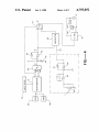
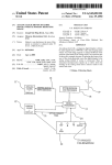
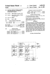
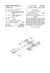
FIG. 1 is a block diagram schematically showing the
adjustment of sensitivity by actually making copies of
such a test document.
control circuit of an exposure control device according
to an embodiment of the present invention,
SUMMARY OF THE INVENTION
45
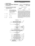
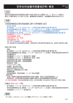
FIG. 2 is a ?ow chart for the operation of the control
It is therefore an object of the present invention to
circuit shown in FIG. 1,
provide an exposure control device for a copier with
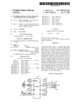
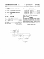
FIG. 3 is another ?ow chart for the operation of the
which the user needs only to press the print button once
control circuit shown in FIG. 1,
to automatically obtain copies with exposure varied in a
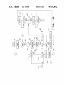
FIG. 4 is a circuit diagram of an exposure control
stepwise fashion.
50 device for a copier according to another embodiment of
It is another object of the present invention to pro
the present invention,
vide a copier with which the user can determine and set
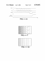
FIG. 5 is a time chart for explaining the transmission
of exposure data from the microcomputer to the digital
to-analog converter of the exposure control device of
many times.
55
FIG. 4,
The above and other objects are achieved in one
FIG. 6 is a flow chart for the operation of the mi
aspect of the present invention by providing an expo
crocomputer shown in FIG. 4 according to one em
sure control device for a copier which comprises, in
bodiment of the present invention,
addition to exposure selecting means for specifying
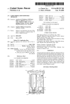
FIG. 7 is a schematic drawing showing a copy ob
exposure in a stepwise fashion and exposure adjusting
tained in the test mode of operation according to the
means for adjusting exposure by an optical system in
flow chart of FIG. 6,
response to a signal from the aforementioned exposure
FIG. 8 is a portion of a flow chart for the operation of
selecting means, exposure varying means for automati
the microcomputer shown in FIG. 4 according to an
cally varying the exposure by the optical system se
quentially and in a stepwise fashion and control means 65 other embodiment of the present invention,
the optimum exposure sensitivity by only one copying
operation instead of repeating adjustments and testing
for controlling the copying operation of the copier
corresponding to the timing of the changes in exposure
by the aforementioned exposure varying means. The
FIGS. 9A and 9B are a flow chart for the operation of
the microcomputer shown in FIG. 4 according to still
another embodiment of the present invention, and
3
4,755,852
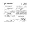
FIG. 10 is a schematic drawing showing an example
of result of copying operation according to the ?ow
chart of FIGS. 9A and 9B.
DETAILED DESCRIPTION OF THE
INVENTION
With reference to FIG. 1 which is a block diagram of
a control circuit embodying the present invention, nu
meral 11 indicates a microcomputer which is operated
according to programs for functions of exposure vary
ing means and copying control means. On the input side
of this microcomputer 11, there is connected thereto a
control panel 17 with various keys and buttons includ
ing ?ve exposure selecting buttons 12 with which expo
4
are desired, for example, the divider is selected to be
5+ 1:6. The addition of l is required if it is also desired
to obtain an image by the so-called automatic exposure.
After the timer is thus set, a counter for counting the
number of stepwise variations in exposure is reset to 0
(n6) and 1 is then added to this counter (n7). Thereafter,
the microcomputer 11 operates the circuit changing
switch 19 to the side of the standard voltage control
circuit 18 and transmits to the standard voltage control
circuit 18 a value signal indicative of the level of expo
sure corresponding to the value in the counter. In re
sponse, the standard voltage control circuit 18 transmits
through the circuit changing switch 19 to the copy
lamp control circuit 20 a signal indicative of the afore
mentioned level of exposure (n8) and copying is ef
fected thereafter (n9).
This copying process lasts for a time period set by the
timer in Step n5. At the end of this time period (YES in
button 14 for transmitting another command that expo
n10), the content of the counter is again increased by 1
sure is going to be controlled automatically, a TEST
button 15 for causing the microcomputer 11 to perform 20 (n7) if the maximum value (5 in this example because
there are ?ve exposure selecting buttons 12) has not
the aforementioned functions of exposure varying
sure can be set in ?ve different steps 1 through 5, a
MANUAL button 13 for transmitting a command that
exposure is going to be controlled manually, an AUTO
been reached (NO in n11) and Steps n7 to n11 are re
peated. This is equivalent to copying the document by
16 for causing the copier to carry out a copying opera
changing the exposure ?ve times in a stepwise fashion.
tion. Connected to the output port of the microcom
After the exposure has been varied the maximum
puter 11 is a standard voltage control circuit 18 for 25
means and copying control means, and a PRINT button
applying to the optical system (not shown) of the copier
number of times (YES in n11), the microcomputer 11
a standard voltage corresponding to the level of expo
sure set in a stepwise fashion by one of the exposure
operates the circuit changing switch 19 to the side of the
subtracter circuit 22 (n12). Thereafter, copying is re
selecting buttons 12. This standard voltage control cir
sumed (n13) with the copy lamp controlled according
cuit 18 is connected to a copy lamp control circuit 20
to the density of the original document detected by the
density detecting circuit 21. This is continued until the
end of the cycle of copying operation for producing a
through a circuit changing switch 19.
Numeral 21 indicates a density detecting circuit
which is adapted to transmit an output signal indicative
of the density of an original document to be copied
detected by a phototransistor or an image sensor (not
shown) of a known kind. The standard voltage control
circuit 18 and the density detecting circuit 21 are both
copy on one sheet (n14).
If the aforementioned maximum value is 5, for exam
ple, the copy paper is divided into six areas in the direc
tion in which it is transported, each area being exposed
differently with the last area having an image obtained
by automatic exposure adjustment mode of operation.
connected to a subtracter circuit 22 and the difference
Thus, the user can immediately determine visually
between the outputs from the standard voltage control
circuit 18 and the density detecting circuit 21 is also 40 which area has the best image density and select the
exposure selecting button 12 corresponding to the
transmitted to the copy lamp control circuit 22 through
image thus selected as the best. Thereafter, the user can
the circuit changing switch 19. The output port of the
microcomputer 11 is also connected to the circuit
obtain the optimum image density by carrying out the
changing switch 19 directly and connects the copy lamp
copying operation manually. In summary, the user
control circuit 20 either to the standard voltage control 45 makes two copies to obtain one most appropriately
exposed image.
circuit 18 or to the density detecting circuit 21 accord
A program of operation has been described above for
ing to its program.
an exemplary situation where ?ve exposure selecting
Next, the ?ow chart shown in FIG. 2 is referenced to
buttons 12 are provided such that the user can vary the
explain a program for the operation of the control cir
cuit of FIG. 1 whereby copying with varied levels of 50 exposure in ?ve levels. If the copier is provided with a
continuously variable switch instead such that the expo
exposure is effected on a single sheet of copy paper.
sure can be changed nearly continuously, the divider
When the PRINT button 16 is pressed by the user (YES
may be appropriately increased so that intermediate
in n1), the circuit determines whether the TEST button
values can also be selected.
15 has been pressed or not (n2). If the TEST button 15
has not been pressed, the exposure is adjusted either 55 FIG. 3 is a flow chart for the operation of the control
circuit shown in FIG. 1 according to another program
according to the exposure selecting button 12 pressed
whereby a new sheet of copy paper is used for each
by the user (manual mode of operation) or automati
change in the exposure level. Since there is no need to
cally according to the density of the original document
to be copied detected by the density detecting circuit 21
(automatic mode of operation) (n3) and copying is car
ried out with the level of exposure thus determined (n4).
If it is determined in Step n2 that the TEST button 15
has been pressed, a software timer is set (n5) by dividing
by an appropriate number the time required for com
divide each copy paper into areas in this program, there
60 is no need for a timer. Thus, the ?ow chart of FIG. 3 is
identical to that of FIG. 2 except Step n5 in deleted and
Step n9 continues until the copying on this paper is
completed. The other steps are therefore indicated by
the same numerals in FIG. 3 and not separately ex
pleting the copying of the original document which is 65 plained. If the aforementioned maximum value is 5 as in
0
set to be copied and of which the size is known. If the
same variations in exposure as are possible by operating
the aforementioned ?ve exposure selecting buttons 12
the example considered above, six copy sheets are pro
duced by this program and the user is again able to
visually select the best exposure by comparing the pro
5
4,755,852
duced copies. Steps n12 through n14 and n12’ through
6
n14’ may be deleted from the ?ow charts of FIGS. 2
white original document is used with the same exposure
data D will take upon an appropriate value.
and 3 if the user so desires.
In FIG. 4 which is a circuit diagram of an exposure
control device for a copier according to another em
transmitted together with the exposure data D’ to the
subtractor circuit 59 in the case of automatic mode of
bodiment of the present invention, numeral 51 indicates
a microcomputer adapted to process data in units of 8
bits and numeral 52 generally indicates an input device
for the copier and includes a PRINT key and a TEST
The aforementioned document density data VA is
operation. The subtractor circuit 59 serves to modify
the exposure data D’ by the document density data VA
and transmits exposure data D" given by V0+Di—VA
to the copy lamp regulating circuit 58. Thus, VA be
key as explained above in connection with FIG. 1. The 0 comes greater where the original document to be cop
ied is brighter. This makes (V0+Di—V,4) smaller and
input data entered through these keys and/or buttons
the exposure becomes weaker, thereby accomplishing
are received by the microcomputer 51. The program by
the objective of automatic exposure. In the case of man
which the microcomputer 51 controls the operation of
ual mode of operation, on the other hand, the aforemen
the copier is already stored in ROM 19. RAM 18 is used
as working areas for various ?ags and counters when 15 tioned value D represents the level of exposure such
that exposure is uniquely determined if this value is set.
the control program is executed.
In the case of automatic exposure, the value of D serves
The microcomputer 51 computes exposure data D on
to shift the level of exposure as a whole and this value
the basis of the entries from the input device 52. The
changes when exposure sensitivity is set.
exposure data D is an 8-bit data and can be set in 256
A program according to one embodiment of the pres
steps from 0 to 255. The exposure data D calculated by
ent invention for the operation of the microcomputer 51
the microcomputer 51 is serially received by a digital
of FIG. 4 is shown by a ?ow chart in FIG. 6. With
to-analog converter 53 which converts the digital expo—
sure data D into an analog exposure data D. FIG. 2 is a
reference next to this flow chart, the microcomputer 51
lates the brightness of a copy lamp 62 through the phase
copying operation is resumed until it is completed (n35).
control of an AC power source 61 by triggering a triac
FIG. 7 shows schematically how a copy thus obtained
by such a test mode of operation may appear when
N=7. The user can determine the optimum exposure
sensitivity from such a result and set its value by operat
?rstly receives data from the input device 52 (n21). If it
time chart showing this serial transmission of exposure
25 is found that the key which has been operated is the
data D. With reference to FIG. 5, the microcomputer
TEST key (YES in n23), a test ?ag FT is set (n24). If the
51 transmits to the digital-to-analog converter 53 not
PRINT key is subsequently operated (YES in n22), the
only a clock pulse SCK but also the exposure data D as
original document to be copied is scanned (n26) because
8-bit serial data SI, and the digital-to-analog converter
the ?ag is in set condition (YES in n25). There is pro
53 latches the serial data SI for each rise of the clock
vided a counter C used as the indicator of exposure
pulse SCK. Right after the eighth serial data SI be
sensitivity which can be varied in a plurality of steps
comes effective, the microcomputer 51 transmits a
and when the time for starting exposure is reached
strobe pulse STB and the digital-to-analog converter 53
(YES in n27), the counter C is set to l which serves as
transmits the analog exposure data D at the rise of this
its initial value. Thereafter, the exposure data D corre
strobe pulse STB.
35 sponding to the current counter value C is computed
With reference again to FIG. 4, numeral 54 indicates
according to a prede?ned functional relationship f1
an operational ampli?er which receives the exposure
between D and C (n29), and the exposure value D thus
data D and transmits exposure data D’ given by V0+Di
computed is transmitted to the digital-to-analog con
where V0 is a lower limit value determined by a resistor
verter 53, thereby setting the brightness of the copy
55 and i is a constant adjustably determined by another
lamp 62 (n30). Next, the system waits until a predeter
resistor 56. Numeral 57 indicates an analog switch and
mined time period has elapsed (n31) to add 1 to the
serves to transmit the exposure data D’ by a signal from
counter C (n33) unless the counter value C has reached
the microcomputer 51 directly to a copy lamp regulat
a prede?ned maximum value N (NO in n32) and repeats
ing circuit 58 in the case of manual mode of operation
Steps n30 and n31. The photoreceptor of the copier is
and through a subtracter circuit 59 to the copy lamp 45 thereby automatically exposed'with N different levels
regulating circuit 58 in the case of automatic mode of
of exposure sensitivity. When the counter C reaches the
operation. The copy lamp regulating circuit 58 regu
maximum value N, the test ?ag FT is reset (n34) and the
60. The copy lamp regulating circuit 58 also serves to
safeguard against voltage variations of this power
source 61 such that the exposure can be maintained
always at a constant level.
Numeral 63 generally indicates a density detecting
circuit for detecting the density of an original document
to be copied. Numeral 64 indicates a photosensor for
detecting the intensity of the reflected light from the
original document. The photosensor 64 is adapted to
output a voltage proportional to the amount of light
received thereby. Numeral 65 indicates an operational
ampli?er which serves as a buffer and numeral 66 indi
ing a sensitivity setting key (YES in n36) to store the
selected exposure sensitivity A (n37).
If the PRINT key is operated in an ordinary mode of
operation other than the test mode (NO in n25), copy
ing is effected with the set exposure sensitivity A. In this
situation, exposure data D corresponding to the expo
sure sensitivity A is computed from the aforementioned
functional relationship f1 therebetween (n38) and trans
mitted to the digital-to-analog converter 53 (n39) and
cates another operational ampli?er which ampli?es the
output from the photosensor 64 through the operational
ampli?er 65 and thereby outputs document density data
ordinary copying is effected (n40).
when a black original document is used and when a
tured that a different sheet of copy paper is used for
According to the control program described above
by way of the flow chart shown in FIG. 6, a single sheet
VA. Numeral 67 indicates a resistor for adjusting the 65 of copy paper is exposed while the exposure sensitivity
ampli?cation of the operational ampli?er 66 such that
is sequentially changed in a stepwise fashion. Alterna
the difference in voltage applied to the copy lamp 62
tively, however the control program may be so struc
7
4,755,852
8
transmitting the exposure data D thus computed to the
digital~to-analog converter 53 of FIG. 4 (n65). When
exposure with each different level of sensitivity. A flow
chart for such alternative program may be identical to
another predetermined period of time has elapsed (YES
that shown in FIG. 6 except Steps n22 through n34 are
changed as shown in FIG. 8 wherein the steps which
are similar or identical to those in FIG. 6 are indicated
by the same numerals. After the PRINT key is operated
(YES in n22’ with reference to FIG. 8), the counter C is
initialized (n28’) if the test ?ag FT is set (YES in n25’),
indicating the test mode of operation. Thereafter, the
exposure data D is similarly obtained from the counter 10
value C (n29') and then outputted to the digital-to
analog converter 23 (n30'). After the exposure data D is
thus set, copying is effected on a single sheet (n40') with
this exposure data D. Thereafter, the counter value C is
incremented (n33’) and next copying operation is ef 15
in n66), the counter value C is incremented by l (n68) if
it has not reached a prede?ned maximum value N (NO
in n67), thereby changing the exposure condition and
repeating Steps n62 through n66. In this manner, the
photoreceptor of the copier is exposed under N differ
ent conditions. After exposure under all N conditions is
completed (YES in n67), the test ?ag FT is reset (n69)
and the copying operation is continued to the end of the
process (n70). The result of such copying operation may
look as shown in FIG. 10. The user can again determine
from such a result the optimum exposure sensitivity and
set the level of exposure in the case of manual mode of
operation and the level of exposure sensitivity in the
fected with a different level of exposure sensitivity on
another sheet of copy paper. When the counter value C
case of automatic exposure mode of operation. If the
has reached the preset maximum value N (YES in n32’),
exposure setting key is thereafter operated (YES in
the test ?ag FT is reset (n34’). In this program, N sheets
n73), the selected level of exposure M is stored (n74). If
of copy paper are used, each one exposed at a different
the sensitivity setting key is operated instead (YES in
n71), the selected level of exposure sensitivity A is
With a copier programmed as described above, the
stored (n72).
If the PRINT key is operated thereafter (YES in n52)
user has only to operate a speci?ed key to select a test
in an ordinary mode other than the test mode of opera
mode of operation. Copying is thereby effected on a
single sheet or a plurality of sheets of copy paper with 25 tion (NO in n58), exposure data D is computed from the
selected level of exposure M (n77) in the case of manual
stepwise varied levels of exposure sensitivity such that
mode of operation (YES in n75) and from the selected
the user can easily select an optimum setting.
level of exposure sensitivity A (n77) in the case of auto
Still another program embodying the present inven
matic exposure mode of operation (NO in n75). The
tion according to which the microcomputer 1 of FIG. 4
exposure data D thus computed is thereafter outputted
may be operated is explained next by way of the flow
to the digital-to-analog converter 53 (n78) to control the
chart shown in FIGS. 9A and 9B. The RAM 68 in
brightness of the copy lamp 62 and ordinary copying
cludes an auto/manual ?ag FM which indicates the
operation is performed thereafter under this condition
manual mode of operation when it is set and the auto
matic exposure mode of operation when it is reset. After
(n79).
level of sensitivity.
the key input through the input device 52 is read, if it is
35
PRINT key (NO in n52) but the auto/manual key (YES
in n53), the condition of the auto/manual flag FM is
reversed (n54). Thereafter, the connection of the switch
57 is changed according to the condition of the auto/
manual flag FM such that the output of the subtracter
The foregoing description of preferred embodiments
of the invention has been presented for purposes of
illustration and description. It is not intended to be
found that the key which has been operated is not the
exhaustive or to limit the invention to the precise form
disclosed. Modi?cations and variations which may be
40 apparent to a person skilled in the art are intended to be
circuit 59 is selected in the case of automatic exposure
mode when the ?ag FM is reset and the output of the
operational ampli?er 54 is selected in the case of manual
mode of operation when the auto/manual ?ag FM is set 45
(n55).
If the TEST key is operated (YES in n56) thereafter,
the test flag FT is set (n57). If the PRINT key is subse
quently operated (YES in n52), scanning of the original
document to be copied is started (n59) because the test 50
flag FT is then in the set condition (YES in n58). When
a preset time period has elapsed for starting exposure
(YES in n60), the counter C is initialized to l (n61). In
this program, the counter values C are used in the man
ual mode of operation for indicating the steps in which 55
exposure is varied and in the automatic exposure mode
included within the scope of this invention.
What is claimed is:
1. In an exposure control device for a copier compris
ing
exposure selecting means for specifying exposure in
steps, and
exposure adjusting means for adjusting exposure by
an optical system according to a signal from said
exposure selecting means,
the improvement wherein said exposure control de
vice further comprises
exposure varying means for automatically varying
exposure by said optical system sequentially in a
stepwise fashion, and
operation controlling means for performing copying
operation in correspondence with the timing of
of operation for indicating the steps in which exposure
sensitivity is varied. Thus, if the auto/manual ?ag FM is
set, indicating the manual mode of operation (YES in
variation by said exposure varying means.
2. In a copier comprising
n62), exposure data D is calculated from the counter 60
value C by means of a predetermined functional rela
document density detecting means for detecting the
density of a document to be copied and transmit
ting a signal indicative of said detected density,
sensitivity setting means for setting sensitivity of ex
posure to said signal from said document density
tionship f; for the manual mode of operation (n63) and
if the auto/manual ?ag FM is reset, indicating the auto
matic exposure mode of operation (NO in n62), expo
sure data D is calculated from the counter value C by 65
means of another predetermined functional relationship
f] for the automatic exposure mode of operation (n64).
_Thereafter, brightness of the copy lamp 62 is set by
a photoreceptor,
detecting means in automatic exposure mode of
operation, and
exposure control means for controlling exposure on
said photoreceptor according to said detected den
4,755,852
sity by said document density detecting means and
said sensitivity set by said sensitivity setting means,
the improvement wherein said copier further com
10
tor manually or according to the density of a document
to be copied,
the improvement wherein said copier comprises
prises
mode switching means for switching to test mode of 5
operation, and
sensitivity switching means for sequentially varying
said sensitivity automatically in a plurality of steps
mode switching means for switching to test mode of
operation, and
exposure switching means for sequentially varying
exposure nearly continuously between a minimum
value and a maximum value by controlling said
by controlling said sensitivity setting means during
exposure setting means during copying operation
a series of copying operations on one or more
on one sheet of copy paper in said test mode of
sheets of copy paper in said test mode of operation.
3. In a copier with a photoreceptor and exposure
setting means for setting exposure on said photorecep
operation.
*
20
25
30
35
55
60
65
it!
*
*
1K