1
DIGITAL HD VIDEOCASSETTE RECORDER
HVR-1500
ANALOG INPUT BOARD
HVBK-1505
SERVICE MANUAL
Volume 1 1st Edition
! WARNING
This manual is intended for qualified service personnel only.
To reduce the risk of electric shock, fire or injury, do not perform any servicing other than that
contained in the operating instructions unless you are qualified to do so. Refer all servicing to
qualified service personnel.
! WARNUNG
Die Anleitung ist nur für qualifiziertes Fachpersonal bestimmt.
Alle Wartungsarbeiten dürfen nur von qualifiziertem Fachpersonal ausgeführt werden. Um die
Gefahr eines elektrischen Schlages, Feuergefahr und Verletzungen zu vermeiden, sind bei
Wartungsarbeiten strikt die Angaben in der Anleitung zu befolgen. Andere als die angegeben
Wartungsarbeiten dürfen nur von Personen ausgeführt werden, die eine spezielle Befähigung
dazu besitzen.
! AVERTISSEMENT
Ce manual est destiné uniquement aux personnes compétentes en charge de l’entretien. Afin
de réduire les risques de décharge électrique, d’incendie ou de blessure n’effectuer que les
réparations indiquées dans le mode d’emploi à moins d’être qualifié pour en effectuer d’autres.
Pour toute réparation faire appel à une personne compétente uniquement.
HVR-1500
Für Kunden in Deutschland
Entsorgungshinweis: Bitte werfen Sie nur entladene
Batterien in die Sammelboxen beim Handel oder den
Kommunen. Entladen sind Batterien in der Regel dann,
wenn das Gerät abschaltet und signalisiert “Batterie
leer” oder nach längerer Gebrauchsdauer der Batterien
“nicht mehr einwandfrei funktioniert”. Um
sicherzugehen, kleben Sie die Batteriepole z.B. mit
einem Klebestreifen ab oder geben Sie die Batterien
einzeln in einen Plastikbeutel.
Voor de klanten in Nederland
Gooi de batterij niet weg maar lever deze in als klein
chemisch afval (KCA).
For the customers in Taiwan only
HVR-1500
1 (P)
ADVARSEL!
Lithiumbatteri-Eksplosionsfare ved fejlagtig
håndtering.
Udskiftning må kun ske med batteri
af samme fabrikat og type.
Levér det brugte batteri tilbage til leverandøren.
CAUTION
Danger of explosion if battery is incorrectly replaced.
Replace only with the same or equivalent type
recommended by the manufacturer.
Dispose of used batteries according to the
manufacturer’s instructions.
Vorsicht!
Explosionsgefahr bei unsachgemäßem Austausch
der Batterie.
Ersatz nur durch denselben oder einen vom
Hersteller empfohlenen ähnlichen Typ. Entsorgung
gebrauchter Batterien nach Angaben des
Herstellers.
ADVARSEL
Lithiumbatteri - Eksplosjonsfare.
Ved utskifting benyttes kun batteri som
anbefalt av apparatfabrikanten.
Brukt batteri returneres
apparatleverandøren.
VARNING
Explosionsfara vid felaktigt batteribyte.
Använd samma batterityp eller en likvärdig typ
som rekommenderas av apparattillverkaren.
Kassera använt batteri enligt gällande
föreskrifter.
VAROITUS
ATTENTION
Il y a danger d’explosion s’il y a remplacement
incorrect de la batterie.
Remplacer uniquement avec une batterie du même
type ou d’un type équivalent recommandé par le
constructeur.
Mettre au rebut les batteries usagées conformément
aux instructions du fabricant.
2 (P)
Paristo voi räjähtää jos se on virheellisesti
asennettu.
Vaihda paristo ainoastaan laitevalmistajan
suosittelemaan tyyppiin.
Hävitä käytetty paristo valmistajan ohjeiden
mukaisesti.
HVR-1500
Table of Contents
Manual Structure
Purpose of this manual ................................................................. 4
2-13. Equipment and Fixtures List for Check/Adjustment .... 2-18
2-13-1. Equipment for Check/Adjustment ....................... 2-18
2-13-2.
Fixtures and Tools ............................................... 2-19
Related manuals ........................................................................... 4
2-14. Alignment Tapes ........................................................... 2-21
Trademark ..................................................................................... 4
2-15. Tools for Board Extension ............................................ 2-23
2-16. Writing and Rewriting the PLD Internal Data .............. 2-25
2-17. Firmware Update .......................................................... 2-27
1. Installation
2-17-1.
Upgrading the Version Using the
Fixture Board ....................................................... 2-27
1-1.
Operating Conditions ...................................................... 1-1
2-17-2.
Version Upgrade from a PC through RS-422 ..... 2-29
1-2.
Power Supply .................................................................. 1-2
1-2-1.
1-2-2.
Voltage and Power Requirements ......................... 1-2
Recommeded Power Cord ..................................... 1-2
2-18. Internal Video Test Signal ............................................ 2-31
2-19. Service Action after Replacing or
Repairing the Board ...................................................... 2-31
1-3.
Supplied Accessories ...................................................... 1-3
2-20. Removing/Installing Flexible Card Wire ...................... 2-32
1-4.
Optional Accessories ...................................................... 1-3
2-21. Unleaded Solder ............................................................ 2-35
1-5.
Matching Connectors/Cables .......................................... 1-3
2-22. Precautions for use of Condensation Sensor ................ 2-35
1-6.
Input/Output Signals of the Connectors ......................... 1-4
1-7.
Installation Setup and Adjustment .................................. 1-6
1-7-1.
1-7-2.
Front Panel Setting ................................................ 1-6
System Adjustment After Installation ................... 1-6
3. Error Messages
3-1.
Alarm Display ................................................................. 3-1
3-1-1.
2. Service Overview
3-2.
2-1.
Location of Main Parts ................................................... 2-1
2-1-1.
2-1-2.
Location of Printed Circuit Boards ....................... 2-1
Location of Main Mechanical Parts ...................... 2-4
2-2.
Function and Location of Sensors .................................. 2-5
2-3.
Functions of Cassette ...................................................... 2-7
2-4.
How to Take Out the Cassette Whose Tape is Slacked
(MANUAL EJECT) ........................................................ 2-8
2-5.
Head Cleaning when Head Clogging Occurs ................. 2-8
2-6.
Operating the VTR without a Cassette Tape .................. 2-9
2-7. Removing/Installing the Cabinets ................................. 2-10
2-7-1.
Removal/Installation of the Top Panel ................ 2-10
2-7-2.
2-7-3.
Removal/Installation of the Bottom Plate ........... 2-10
Removal/Installation of the Front Panel .............. 2-11
2-7-4.
Removal/Installation of the Rear Panel ............... 2-11
2-8.
Removing/Installing the Cassette Compartment .......... 2-12
2-9.
Function of Indicators on Circuit Boards ..................... 2-13
2-10. Switch Setting on Circuit Boards ................................. 2-14
2-11. Circuit Protection Parts (Fuse/IC Link) ........................ 2-15
2-12. Replacing NV-RAM and Memory Backup Battery ..... 2-16
HVR-1500
Alarm Display when the Main Power is
Turned On ............................................................. 3-1
Error Codes ..................................................................... 3-3
3-2-1.
3-2-2.
Display of Previously Detected Error Codes ........ 3-5
Main Codes and Sub Codes .................................. 3-6
3-2-3.
3-2-4.
Error Codes ........................................................... 3-8
Possible Causes of Errors .................................... 3-14
4. Maintenance Menu
4-1.
Menu Structure ............................................................... 4-1
4-2. How to Operate Maintenance Menu ............................... 4-3
4-2-1.
Location and Function of Switches ....................... 4-3
4-2-2.
4-2-3.
4-3.
How to Enter the Maintenance Menu ................... 4-3
How to Exit the Maintenance Menu ..................... 4-3
Contents of Maintenance Menu ...................................... 4-4
4-3-1.
4-3-2.
MENU DATA CONTROL ................................... 4-4
EDIT CHECK ....................................................... 4-7
4-3-3.
4-3-4.
SERVO CHECK ................................................... 4-9
SERVO ADJUST ................................................ 4-24
4-3-5.
4-3-6.
TAPE PATH ADJUST ........................................ 4-31
ELECTRICAL ADJUST ..................................... 4-32
1
4-3-7.
4-3-8.
SERVICE SUPPORT .......................................... 4-40
OTHERS ............................................................. 4-42
6-21. Head Cleaner Solenoid Replacement ........................... 6-60
6-22. Cassette Compartment Motor Replacement ................. 6-62
6-23. Removing/Installing the MD Assembly ....................... 6-64
5. Periodic Inspection and Maintenance
5-1.
Periodic Inspection List .................................................. 5-1
5-2. Hours Meter .................................................................... 5-2
5-2-1.
Displaying Hours Meter Information .................... 5-3
5-2-2.
How to Reset Hours Meter .................................... 5-4
5-3. Cleaning .......................................................................... 5-5
5-3-1.
Video Head Cleaning Procedure ........................... 5-5
5-3-2.
5-3-3.
Tape Running Path Cleaning ................................. 5-5
Cassette Compartment Entrance Cleaning ............ 5-6
5-3-4.
5-3-5.
Cassette Compartment Shaft Cleaning .................. 5-6
Cassette Guide Assembly Cleaning ...................... 5-6
6-24. LCD Replacement ........................................................ 6-65
6-25. Removing/Installing the Switching Regulator .............. 6-65
6-26. Removing/Installing the Mounted Board ..................... 6-66
6-26-1. Plug-in Board ...................................................... 6-66
6-26-2.
6-26-3.
CN-1968A Board ................................................ 6-66
CN-2905 Board ................................................... 6-66
6-26-4.
6-26-5.
DDE-22 Board ..................................................... 6-67
DR-428BG Board ................................................ 6-67
6-26-6.
6-26-7.
DVP-42 Board ..................................................... 6-68
HP-136 Board ...................................................... 6-69
6-26-8.
6-26-9.
HPR-20 Board ..................................................... 6-69
KY-614 Board ..................................................... 6-70
6-26-10. KY-616 Board ..................................................... 6-70
6-26-11. MB-1098 Board ................................................... 6-71
6. Replacement of Mechanical Parts
6-26-12. RP-133 Board and RT-10 Board ......................... 6-72
6-26-13. SDI-94 Board ...................................................... 6-73
6-1.
6-26-14. SE-521G Board ................................................... 6-73
6-26-15. SE-522G Board ................................................... 6-74
General Information on Parts Replacement and
Adjustment ...................................................................... 6-1
6-1-1.
6-1-2.
6-1-3.
Preparation Before Starting Parts Replacement .... 6-1
Drum Assembly ..................................................... 6-1
Grease .................................................................... 6-1
6-1-4.
Tightening Torque and Handling of Washers ....... 6-2
6-26-16. SE-525G Board (LED Holder Assembly) ........... 6-74
7. Tape Path Alignment
6-2.
Drum Replacement ......................................................... 6-3
7-1.
General Information for Tape Path Adjustment ............. 7-1
6-3.
Brake Solenoid Replacement .......................................... 6-8
7-2.
Tape Path Adjustment ..................................................... 7-7
6-4.
Pinch Roller Replacement ............................................ 6-12
7-3.
RF Switching Position Adjustment .............................. 7-10
6-5.
Elevator Cam Replacement .......................................... 6-14
7-4.
Tape Path Adjustment Confirmation ............................ 7-13
6-6.
Pinch Solenoid Assembly Replacement ....................... 6-16
7-5.
Search Forward (x5) Waveform Check ....................... 7-14
6-7.
Reel Motor (T) Assembly Replacement ....................... 6-18
7-6.
Search Reverse (x5) Waveform Check ........................ 7-15
6-8.
Reel Motor (S) Assembly Replacement ....................... 6-23
7-7.
RF Waveform Raiseup Check ...................................... 7-16
6-9.
M Stop Solenoid Replacement ..................................... 6-27
7-8.
Tape Curl Check at Tape Guide ................................... 7-17
6-10. S Tension Regulator Assembly Replacement ............... 6-31
6-11. T Drawer Arm Assembly Replacement ........................ 6-34
6-12. TG1 Arm Assembly Replacement ................................ 6-36
8. Electrical Alignment
6-13. TG8 Arm Assembly Replacement ................................ 6-38
6-14. Rail Assembly Replacement ......................................... 6-40
6-15. Capstan Motor Replacement ......................................... 6-46
6-16. Loading Motor Replacement ........................................ 6-48
6-17. Reel Shift Motor Assembly Replacement .................... 6-49
6-18. MIC Assembly Replacement ........................................ 6-51
6-19. MIC Holder Assembly Replacement ............................ 6-55
8-1.
Electrical Alignment Overview ...................................... 8-1
8-1-1.
8-1-2.
Precautions ............................................................ 8-1
Outline of Electrical Alignment ............................ 8-1
8-1-3.
Equipment and Fixture .......................................... 8-1
8-2. Audio Adjustment ........................................................... 8-2
8-2-1.
Audio Output Level Adjustment ........................... 8-2
8-2-2.
Audio EE Level Adjustment ................................. 8-2
6-20. HC Roller Assembly Replacement ............................... 6-57
2
HVR-1500
8-3. Video Adjustment ........................................................... 8-3
8-3-1.
Preparation in the 59.94 Hz Mode ........................ 8-3
8-3-2.
8-3-3.
HCK Frequency Adjustment ................................. 8-4
HD HCK Frequency Adjustment .......................... 8-4
8-3-4.
8-3-5.
SYNC Phase Adjustment ...................................... 8-5
CHARACTER DC Adjustment ............................ 8-6
8-3-6.
8-3-7.
CF DET CENTER Adjustment ............................. 8-6
S VIDEO Y Level Adjustment .............................. 8-7
8-3-8.
8-3-9.
COMPOSITE Video Level Adjustment ................ 8-7
COMPOSITE Burst Level Adjustment ................. 8-8
8-3-10.
8-3-11.
S VIDEO Chroma Level Adjustment .................... 8-8
COMPONENT SD Y Level Adjustment .............. 8-9
8-3-12.
8-3-13.
COMPONENT HD Y Level Adjustment .............. 8-9
COMPONENT Y REC Level Adjustment .......... 8-10
8-3-14.
8-3-15.
COMPONENT R-Y REC Level Adjustment ...... 8-10
COMPONENT B-Y REC Level Adjustment ...... 8-11
8-3-16.
8-3-17.
COMPOSITE Y REC Level Check .................... 8-11
COMPOSITE Chroma REC Level Check .......... 8-12
8-3-18.
8-3-19.
S VIDEO Y REC Level Check ........................... 8-12
S VIDEO Chroma REC Level Check ................. 8-13
8-3-20.
Adjustment in the 50 Hz Mode ........................... 8-14
8-4.
SDI Free-running Adjustment ...................................... 8-15
8-5.
LCD Adjustment ........................................................... 8-16
8-5-1.
8-5-2.
Contrast Adjustment ............................................ 8-16
V-COM Adjustment ............................................ 8-16
8-5-3.
8-5-4.
Sample Hold Timing Adjustment ....................... 8-17
White Balance Adjustment .................................. 8-18
8-6.
Adjustment Related Parts Layout Diagram .................. 8-19
HVR-1500
3
Manual Structure
Purpose of this manual
This manual is the Service Manual Volume 1 for the digital HD videocassette
recorder HVR-1500, the option board Analog Input Board HVBK-1505.
This manual contains the maintenance information of this equipment, and servicing
information necessary for parts replacement and adjustments.
Related manuals
In addition to this Service Manual Volume 1, the following manuals are provided.
. Operation Instructions
HVR-1500 (Supplied with HVR-1500 )
Part number : 3-993-538-1X
HVBK-1505 (Supplied with HVBK-1505)
Part number : 3-993-605-0X
. CD-ROM Manual (Supplied with SY model)
This manual contains the Japanese, English, French, German, Italian, and Spanish
operating instructions (PDF).
Part number : 3-993-560-0X
. Service Manual Volume 2 (Not Supplied with equipment)
Contains the semiconductor pin assignments, parts lists, block diagrams, board
layouts and schematic diagrams.
Part number : 9-968-317-0X
. “Semiconductor Pin Assignments” CD-ROM (Available on request)
This “Semiconductor Pin Assignments” CD-ROM allows you to search for
semiconductors used in Broadcast and Professional equipment.
The service manual volume 2 contains a complete list of semiconductors and their
ID Nos., and thus should be used together with the CD-ROM.
Part number: 9-968-546-06
Trademark
Trademark or registered trademark used in this manual is follows.
. Windows is a registered trademark of Microsoft Corporation.
4
HVR-1500
Section 1
Installation
Be sure to install the HVR-1500 in location satisfying the required operational environment described
below to assure the HVR-1500 superior performance and to maintain the excellent serviceability and
accessibility.
1-1. Operating Conditions
c
Good air circulation is essential to prevent internal heat build-up. Place the unit in location with sufficient
air circulation.
Do not block the ventilation holes of the cabinet and the front and rear panels.
Operating temperature: 5 dC to 40 dC
Operating humidity: Less than 80 %
Storage temperature: _20 dC to 60 dC
Locations to avoid:
. Areas where the unit will be exposed to direct sunlight of any other strong lights.
. Areas near heat sources.
. Dusty areas or areas subject to vibration.
. Areas with strong magnetic field.
. Areas with much electrical noise.
. Areas with much static electricity.
. Areas windtight.
Tilt allowance:
Within 30d (Do not slant the front and rear of the unit more than 30d.)
c
Fix the unit securely to avoid drop when the unit is operated at not-horizontal place.
HVR-1500
1-1
1-2. Power Supply
1-2-1. Voltage and Power Requirements
This unit’s power line has a switching regulator.
c
Be sure to operate the unit within the range of following
power voltage.
Power voltage:
Power frequency:
Power consumption:
Rush current:
AC 100 to 240 V ± 10 %
50 Hz or 60 Hz
60 W
Power voltage 100 V IN: 12 A
Power voltage 240 V IN: 34 A
n
AC power supply is required a capacity which is commensurate with rush current.
If the capacity of the AC power supply is not enough, the
breaker of AC power of a supply side may operate or this
unit may not operate normally.
1-2-2. Recommeded Power Cord
This unit does not come with a power cord.
To get a power cord, please contact your local Sony Sales
Office/Service Center.
w
. Use the approved Power Cord (3-core mains lead)/
Appliance Connector/Plug with earthing-contacts that
conforms to the safety regulations of each country if
applicable.
. Use the Power Cord (3-core mains lead)/Appliance
Connector/Plug conforming to the proper ratings (Voltage, Ampere).
For customers in the U.S.A. and Canada:
1 Power cord 125 V 10 A (2.4 m):
! 1-551-812-11
2 Plug holder (Brown):
3-613-640-01
1
2
For customers in the United Kingdom:
1 Power cord 250 V 10 A (2.4 m):
2 Plug holder (Brown):
1
2
AC inlet
! 1-782-165-11
3-613-640-01
AC inlet
For customers in European countries except the United
Kingdom:
1 Power cord 250 V 10 A (2.0 m):
! 1-551-631-15
2 Plug holder (Brown):
3-613-640-01
1
2
For customers in the China:
1 Power cord 250 V 10 A (1.8 m):
2 Plug holder (Brown):
1
2
AC inlet
! 1-783-481-41
3-613-640-01
AC inlet
If you have questions on the use of the above Power Cord/
Appliance Connector/Plug, please contact your local Sony
Sales Office/Service Center.
w
. Never use an injured power cord.
1-2
If the unit is used in the area except above, please contact
your local Sony Sales Office/Service Center.
HVR-1500
1-3. Supplied Accessories
. Operating instructions :
. Operating instructions (CD-ROM) :
1
1
1-4. Optional Accessories
.
.
.
.
.
AC power cord
Analog input board :
9-pin remote conrtrol cable :
Remote control unit :
Digital video cassette :
. Cleaning cassette tape :
HVBK-1505
RCC-5G (Length : 5 m (16 ft))
DSRM-10
PDV-184*/124*/94*/64* (Standard-size (L) )
PDVM-40*/32*/22*/12* (Mini-size (S) )
PHDV-276DM*/186DM*/124DM*/64DM* (Standard-size (L) )
PHDVM-63DM* (Mini-size (S) )
n
The * in each model name is actually “ME” (indicating that a cassette
memory is contained), “N” (indicating that no cassette memory is
contained) or “MEM” (indicating a master tape).
PDV12CL (Standard size), PDVM12CL (Mini size)
1-5. Matching Connectors/Cables
When external cables are connected to the connector on a connector panel during maintenance, the
following connectors, cables (or their equivalents) must be used.
Connectors on HVR-1500 Side
Matching connector/cable
Panel indication
Designation
Sony Part No.
ANALOG IN
REF. VIDEO IN (SD/HD)
TC IN
VIDEO IN
BNC, MALE
1-560-069-11
AUDIO IN CH-1/3, 2/4
When HVBK-1505
is attached
XLR 3P, MALE
1-508-083-11
BNC, MALE
1-560-069-11
MONITOR AUDIO
PIN PLUG
Standard Product
AUDIO OUT CH-1/3, 2/4
XLR 3P, FEMALE
1-508-084-11
HDV/DV
IEEE1394 6P (1 m)
IEEE1394 6P (3.5 m)
1-782-408-21
1-791-184-11
SDI IN
BNC, MALE
1-560-069-11
SDI OUT1, 2
BNC, MALE
1-560-069-11
HD-SDI OUT 1, 2
BNC, MALE
1-560-069-11
AUDIO I/O (AES/EBU)
IN CH-1/2, 3/4
BNC, MALE
1-560-069-11
BNC, MALE
1-560-069-11
D-SUB 9P, MALE
1-560-651-11
ANALOG OUT
TC OUT
VIDEO OUT
OUT CH-1/2, 3/4
REMOTE
HVR-1500
Remark
When HVBK-1505
is attached
1-3
1-6. Input/Output Signals of the Connectors
INPUT
REF. VIDEO IN (SD/HD) :
VIDEO IN:
SDI IN:
AUDIO IN:
AUDIO I/O (AES/EBU) :
TC IN:
HDV/DV:
OUTPUT
VIDEO OUT:
SDI OUT:
1-4
BNC x 2 (loop-through with 75 Z automatic terminator)
SD composite sync, black burst: 0.286 V p-p (525/60) or 0.3 V p-p (625/
50), 75 Z, negative sync
HD tri-level sync: 0.3 V, 75 Z, negative sync
BNC x 4 (When HVBK-1505 is attached)
Composite
Y/S-Y/CPST and 1 loop-through connector with 75 Z automatic
terminator: 1.0 V p-p, 75 Z, negative sync
Component
Y/S-Y/CPST: 1.0 V p-p, 75 Z, negative sync
R-Y/S-C and B-Y: 0.7 V p-p (75 % color bars for 525/59.94 or 100%
color bars for 625/50) , 75 Z
S-video
Y/S-Y/CPST: 1.0 V p-p, 75 Z, negative sync
R-Y/S-C: 0.286 V p-p (525/59.94) or 0.3 V p-p (625/50), 75 Z (burst
level)
BNC x 1
Serial digital interface format (270 Mbps), SMPTE 259M/ITU-R BT.656
XLR 3-pin x 2, FEMALE (When HVBK-1505 is attached)
+4/0/_3*/_6 dBm , high impedance, balanced
*
: For 625/50 only
BNC x 2
Complying with AES-3id-1995
BNC x 1, SMPTE timecode (525/59.94) or EBU timecode (625/50)
0.5 V p-p to 18 V p-p, 3.3 kZ, unbalanced
6-pin IEEE 1394 connector x 1
BNC x 3
Composite
Y/CPST: 1.0 V p-p, 75 Z, negative sync
Component (SD)
Y/CPST: 1.0 V p-p, 75 Z, negative sync
Pr/R-Y/S-C and Pb/B-Y/S-Y: 0.7 V p-p (75% color bars for 525/59.94
or 100% color bars for 625/50),75 Z
Component (HD)
Y: 1.0 V p-p, 75 Z, negative sync
Pr, Pb: 0.7 V p-p, 75 Z
S-video
Pb/B-Y/S-Y: 1.0 V p-p, 75 Z, negative sync
Pr/R-Y/S-C: 0.286 V p-p (525/59.94) or 0.3 V p-p (625/50), 75 Z (burst
level)
Monitor video output
BNC x 1
(SUPER) CPST: 1.0 V p-p, 75 Z, negative sync
BNC x 2
Serial digital interface format (270 Mbps), SMPTE 259M/ITU-R BT.656
HVR-1500
HD-SDI OUT:
AUDIO OUT:
MONITOR AUDIO:
PHONES:
AUDIO I/O (AES/EBU) :
TC OUT:
HDV/DV:
BNC x 2
Serial digital interface format (1.485, 1.485/1.001 Gbps), SMPTE 292M
XLR 3-pin x 2, MALE
+4/0/_3*/_6 dBu, 600 Z loading, low impedance, balanced
*
: For 625/50 only
Phono jack x 1
_∞ to _11 dBu ± 1 dB (_20 dBFS) /_9 dBu ± 1 dB (_18 dBFS), 47 kZ,
unbalanced
Stereo phone jack x 1
_∞ to _13 dBu (_20 dBFS) /_11 dBu (_18 dBFS), 8 Z, unbalanced
BNC x 2
Complying with AES-3id-1995
BNC x 1
SMPTE timecode (525/59.94), EBU timecode (625/50)
2.2 V p-p ± 3 dB (when 600 Z terminated) , unbalanced
6-pin IEEE 1394 connector
Remote control connectors
CONTROL-S:
Stereo minijack x 1
HDV/DV:
6-pin IEEE 1394 connector
REMOTE (D-sub 9-pin : MALE)
1
5
9
6
_ EXT VIEW _
Pin No.
Controlling Device
1
FRAME GROUND
FRAME GROUND
2
RECEIVE A
TRANSMIT A
3
TRANSMIT B
RECEIVE B
4
TRANSMIT COMMON
RECEIVE COMMON
5
PRIORITY IN
PRIORITY OUT
6
RECEIVE COMMON
TRANSMIT COMMON
7
RECEIVE B
TRANSMIT B
8
TRANSMIT A
RECEIVE A
9
FRAME GROUND
FRAME GROUND
HVR-1500
Controlled Device
1-5
1-7. Installation Setup and Adjustment
Layout of switch and buttons on the front panel
1-7-1. Front Panel Setting
Front panel
1. i.LINK INPUT SELECT button setting
i.LINK : HDV:
Video and audio signals in HDV
format
i.LINK : DV *:
Video and audio signals in DV
format
i.LINK : DVCAM *: Video and audio signals in
DVCAM format
*
: The display follows the recording format setting in
the REC FORMAT menu item. (Refer to the
operating instructions for details)
2. VIDEO INPUT SELECT button setting
COMPOSITE:
Composite video signal
(When HVBK-1505 is attached)
S VIDEO:
S-video (separated Y and C)
signals (When HVBK-1505 is
attached)
COMPONENT SD: Component video signals
(When HVBK-1505 is attached)
SDI:
SDI video signal
SG:
Video test signal
3. AUDIO INPUT SELECT button setting
ANALOG:
Analog audio signal
(When HVBK-1505 is attached)
AES/EBU:
Digital audio signal in AES/
EBU format
SDI:
Digital audio signal in SDI
format
SG:
Audio test signal
3. CH1 1/2 button
CH2 3/4 button
4. VARIABLE switch
2. VIDEO button
1. i.LINK button
1-7-2. System Adjustment After Installation
Observe the following precautions when this equipment is
used for editing system.
. The REF. VIDEO IN requires video signal which is in
conformity with the RS-170A (525/60).
. Adjust the sync phase of this equipment to the system
sync with [SYNC PHASE] control of the setup menu.
. Adjust the SCH phase of this equipment to the system
SCH with [SUB CARRIER] control of the setup menu.
. When this unit is connected to a switcher that does not
have the sync switching function, the SYNC/BURST
level adjustment is required.
4. AUDIO VARIABLE switch setting
PRESET :
Sets both the REC and PB levels
to the normal level.
REC :
Sets the REC audio level of the
channels respectively with the
CH-1/2/3/4 knobs.
PB :
Sets the PB audio level of the
channels respectively with the
CH-1/2/3/4 knobs.
1-6
HVR-1500
Section 2
Service Overview
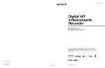
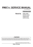
2-1. Location of Main Parts
2-1-1. Location of Printed Circuit Boards
Switching regulator
!=
!]
7
8
1
9
2
3
4
6
0
5
!-
![
Board name
Circuit function
1
MB-1098
Motherboard
2
RP-133
RF REC/PB, ATF Detection
3
HP-136
Headphone, Remote Control
4
KY-614
Key Board
5
KY-616
Graphics Renderer
6
RT-10
HDV Equalizer
7
CN-1968A
HDV/DV Connector Board
8
DDE-22 (HVBK-1505)
Analog Video/Audio Input Board
9
AVP-7
Analog Video/Audio Output Board
!/
SDI-94
Digital Input/Output Board
!-
SSS-12
System/Servo Control
!=
CN-2905
Intermediate Board
![
DVP-42
DV Video/Audio Digital Process
!]
HPR-20
HDV Video/Audio Digital Process
HVR-1500
2-1
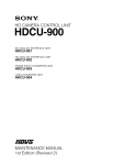
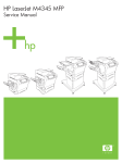
Locations of mechanism deck
1
2
6
5
3
4
Board name
Circuit function
1
SE-521G
Threading Mode Sensor, Tape End Sensor, Loading Motor FG Sensor
2
SE-538G
Tension Sensor
3
CN-1863
REC INHIBIT Sensor, MIC Terminal
4
SE-525G
Tape Top/End LED
5
SE-522G
Tape Top Sensor, Reel Position Sensor
6
DR-428BG
Drum/Reel/Capstan Control Board
2-2
HVR-1500
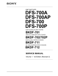
Locations of cassette compartment
1
5
4
2
3
Board name
Circuit function
1
CN-2021G
Intermediate Board
2
CC-83G
Cassette Compartment Mode Detection, Intermediate Board
3
CC-85G
Cassette In Detection
4
CC-84G
Cassette Type Detection
5
CN-2022G
Intermediate Board
HVR-1500
2-3
2-1-2. Location of Main Mechanical Parts
2
1
@]
3
@[
@=
4
5
@-
6
7
@/
!.
8
!,
!'
!;
9
!\
0
!]
!-!=
![
@\
1
2
3
4
5
6
7
8
9
!/
!!=
![
2-4
Head cleaning solenoid
Loading motor
TG1 arm assembly
Shuttle (left) assembly
S tension regulator assembly
S reel motor
S brake assembly
Brake solenoid
M stop solenoid assembly
T brake assembly
MIC assembly
MIC holder assembly
T reel motor
!]
!\
!;
!'
!,
!.
@/
@@=
@[
@]
@\
Shuttle (right) assembly
T drawer arm assembly
TG8 arm assembly
Capstan motor
Elevator cam
Pinch solenoid assembly
Reel shift motor
Pinch roller
HC roller assembly
Drum assembly
Rail assembly
Cassette compartment motor assembly
HVR-1500
2-2. Function and Location of Sensors
(1) Mechanism deck
!=
![
1
2
4
3
!/
!-
5
6
7
9
1, 2 Mode sensor
Detects the mechanism position during threading.
3
Tape top/end detect LED
Detects the top and end of a tape.
4
Condensation sensor
Detects condensation occurred in DSR-1500/
1500P.
5
Tape top sensor
Detects the beginning of a tape that runs in the
REV direction.
6
Reel position sensors (4 pieces) (Mini, M, Standard reel position)
Detects the reel table position at the each specified
reel position according to the cassette type.
7
Reel FG sensor (Take-up side)
Detects rotation of the take-up reel table. The FG
output of the sensor is sent to the servo circuit and
used to control the rotating speed and torque of the
reel motor.
8
Record proof sensor (common to standard, M and
mini size cassettes)
Protects a tape from mis-recording.
HVR-1500
8
9 Cassette memory terminal
Determines whether cassette memory is used, and
reads and writes data to and from the cassette memory.
!/ Tension sensor
The tension arm keeps the tension of a running tape
constant during recording and playing. The tension
sensor detects the mechanical position of the tension
arm.
!- Reel FG sensor (Supply side)
Detects the rotation of the supply reel table. The PG
output of the sensor is input to the servo circuit and
controls the rotating speed and torque of the reel
motor.
!= Tape end sensor
Detects the end of a tape that runs in the FWD direction.
![ Threading motor FG sensor
Detects the rotation speed of the gearbox motor. The
FG output of the sensor is input to the servo circuit and
controls the threading speed so that excessive force is
not applied to the tape during threading.
2-5
(2) Cassette compartment
1 S3
2 PH1
2 PH2
2 PH3
3 PH4
1 S1
1 S2
3 PH5
3 PH7
3 PH6
1 The sensors S1, S2 and S3 discriminate the inserted cassette type among the mini, M, standard
cassettes and the cassette adaptor for DVCPRO by on/off of the sensors.
2 The sensors PH1, PH2 and PH3 detect the movement of a cassette compartment by their combination.
3 The sensors PH4 and PH5 detect that a mini cassette got inserted.
The sensors PH4 and PH6 detect that a M cassette got inserted.
The sensors PH4 and PH7 detect that a standard cassette got inserted.
2-6
HVR-1500
2-3. Functions of Cassette
Standard cassette, M cassette
Cassette cover release claw
Record proof
hole
4 3 2 1
Record proof plug
Reel rotation stopper
Mini cassette
Hole and plug for record proof
Record enable
REC
SAVE
Cassette cover release claw
Record protect
REC
SAVE
. This plug controls the record proof
switch according to open or close
position.
Record proof
hole
4 3 2 1
Reel rotation stopper
Record proof plug
Pin No.
Function
Equipped with built-in memory
Not equipped with built-in memory
+DC
Detecting tape thickness
2
DATA
Detecting tape type (Example: ME/MP)
3
CLOCK
Detecting tape application (Example: consumer/professional)
4
GND
_
1
HVR-1500
2-7
2-4. How to Take Out the Cassette
Whose Tape is Slacked (MANUAL
EJECT)
(1)
(2)
(3)
(4)
Turn the power off.
Remove the top panel. (Refer to Section 2-7-1.)
Remove the front panel. (Refer to Section 2-7-3.)
Turn the manual eject gear A (red) in the arrow
direction with a phillips screwdriver while pressing the
gear. When the tape comes to slack, turn the reel table
from the front side utilizing a skewer and wind the
tape.
n
In a case of standard cassette and M cassette :
Turn the reel table (T)
In a case of mini cassette :
Turn the reel table (S)
(5) Repeat step (4) until each guide comes to the unthreading end position and furthermore the tape completely
returns into the cassette.
(6) Turn the manual eject gear B (red) in the arrow
direction until the cassette compartment completely
comes into cassette out state.
Manual eject gear A (red)
2-5. Head Cleaning when Head Clogging
Occurs
Clean the video head as follows when the video head gets
dirty.
Procedure to Use the Cleaning Cassette
n
Use only the cleaning cassette tape as follows.
If another cleaning cassette tape is used, abnormal abrasion
or breakage of the video head could occur.
Cleaning cassette tapes :
PDV12CL (Standard)
PDVM12CL (Mini)
1. Insert the specific cleaning cassette tape in this unit.
The unit is automatically set in the PLAY mode and
the cleaning tape starts running.
Confirm that the [PLAY] key lights and the display
appears.
2. The cleaning cassette tape is automatically ejected
after running for 10 seconds.
n
Do not rewind the cleaning cassette tape to use it
again.
3. Make sure that the head is no longer dirty.
If the video head is still dirty after step 2 above, clean
the video head as follows.
Procedure to Use the Cleaning Cloth
Reel table (S)
1. Soak the cleaning cloth with cleaning liquid and bring
it into contact lightly with the video head.
2. Turn the upper drum slowly by hand in the rotating
direction of the head (counterclockwise when viewed
from the top) to clean the video head.
m
. Never move the cleaning cloth in the vertical direction
against the video head because it may break the head.
. Turn the power switch off when cleaning the video head.
Manual
eject gear B (red)
Skewer
2-8
Reel table (T)
HVR-1500
2-6. Operating the VTR without a
Cassette Tape
The VTR can be operated without a cassette tape by the
following switch setting.
Switch Setting
1. Remove the cassette compartment from this unit.
2. Turn on switches S401-4 of the SSS-12 board.
3. Then turn on the main power.
Operating Method
Threading
While pressing the S/T reel motors, press the [STOP] key.
The upper drum rotates, threading ring rotates. The unit
enters the threading mode.
The tension arm and the threading ring move to the
specified position, then the threading is completed.
This condition in which the threading is completed is
referred to as the STOP status.
PLAY
Press the [PLAY] key.
The pinch roller is pressed against the capstan shaft to
enter the PLAY status.
When the [PLAY] key is pressed during threading, the
pinch roller is pressed against the capstan shaft to enter the
PLAY status after the threading has completed.
REC
While pressing the record proof sensor on the right side of
the T side reel table, press both the [PLAY] key and the
[REC] key.
The pinch roller is pressed against the capstan shaft to
enter REC status.
When the record proof sensor is released, the REC status is
released and the recorder returns to PLAY status.
Unthreading
Press the [EJECT] key.
Each guide moves to the specified position to complete the
unthreading.
Reel position selection
Press the SET (YES) key on the control panel.
Reel position will be changed as shown below in accordance with the number of pressing the SET (YES) key.
Mini
M
STD
n
Make sure to turn off switches S401-4 on the SSS-12
board after the adjustment.
FF
Press the [F|FWD] key.
The pinch roller is pressed against the capstan shaft to set
the FWD.SEARCH to five-times speed.
REW
Press the [REW] key.
The pinch roller is pressed against the capstan shaft to set
REV.SEARCH to five-times speed.
HVR-1500
2-9
2-7. Removing/Installing the Cabinets
n
Before removing the cabinets, be sure to turn off the main
power.
2-7-1. Removal/Installation of the Top Panel
2-7-2. Removal/Installation of the Bottom
Plate
1. Stand the main unit on the left side.
2. Remove the two screws and remove the bottom plate
in the direction of the arrow.
3. Re-attach the parts in reverse order of the disassembling procedure.
1. Remove the four screws and remove the top panel in
the direction of the arrow.
n
Be careful not to break or peel off the internal packing.
2. Re-attach the parts in reverse order of the disassembling procedure.
Holes
Top panel
B4 x 6
Claws
BVTT3 x 6
Bottom plate
B4 x 6
2-10
BVTT3 x 6
HVR-1500
2-7-3. Removal/Installation of the Front
Panel
1. Remove the top panel. (Refer to Section 2-7-1.)
2. Remove the bottom plate.
(Refer to Section 2-7-2.)
3. Remove the harness (AC PSW) from the
connector (CN2) on the switching regulator.
4. Remove the flexible card wire from the connector (CN500) on the KY-616 board.
5. Remove the harness (KY-MB) from the connector (CN101) on the KY-614 board.
6. Remove the four screws.
7. Pull the front panel to the front to remove it.
8. Re-attach the parts in reverse order of the
disassembling procedure.
2-7-4. Removal/Installation of the Rear Panel
1. Remove the screw (B3 x 5) and toothed washer.
2. Remove the six screws (BV3 x 6) , and remove the
rear panel.
3. Remove the harness from the connector (CN2) on the
CN-1968A board.
4. Re-attach the parts in reverse order of the disassembling procedure.
CN2
BV3 x 6
CN2
Harness
Harness (AC PSW)
B3 x 5
BV3 x 6
Toothed washer
Rear panel
BVTT3 x 6
Harness (KY-MB)
Front panel
Flexible card wire
CN101
Claws CN500 BVTT3 x 6
HVR-1500
2-11
2-8. Removing/Installing the Cassette
Compartment
Removal
1. Remove the top panel. (Refer to Section 2-7-1.)
2. Remove the C cable retainer.
3. Remove the flexible card wire from the connector
(CN1) on the CC-83G board.
4. Remove the two screws and remove the cassette
compartment retainer.
5. Remove the cassette compartment n the direction of
the arrow.
Installation
1. Put in the cassette compartment in the opposite
direction of the arrow and align the four positioning
holes with the four positioning pins.
2. Attach the cassette compartment with the two screws.
3. Connect the flexible card wire to the connector (CN1)
on the CC-83G board.
4. Attach the C cable retainer.
5. Attach the top panel. (Refer to Section 2-7-1.)
C cable retainer
Flexible
card wire
BVTT3 x 6
Cassette compartment
retainer
Positioning hole
Cassette
compartment
CN1
CC-83G
board
Positioning
hole
Positioning
pins
Positioning
holes
Positioning pins
2-12
HVR-1500
2-9. Function of Indicators on Circuit Boards
DDE-22 Board
1
2
3
4
5
6
7
8
A
B
C
D203
D202
D201
D200
D
E
F
G
H
A side (component side)
Ref. No.
Name
Color
Description
Normal state
D200
NON INTER
Green
Blinks in case of non-interlace signal.
OFF
D201
NON STD
Green
Blinks, except for a standard signal.
OFF
D202
VCXO SC LOCK
Red
Lights in case of standard signal
OFF
D203
VCXO H LOCK
Red
Off in case of standard signal
Lights
SDI-94 Board
3
2
D201
E
D
1
C
B
A
A side (component side)
Ref. No.
Name
Color
Description
Normal state
D201
UNLOCK
Red
Lights when SDI output signal is unlock.
OFF
HVR-1500
2-13
2-10. Switch Setting on Circuit Boards
n
Do not change the setting of switches when the “Factory use” is shown in the description.
HPR-20 Board
6
5
4
2
3
1
A
B
S401
C
D
A side (component side)
Ref. No.
Name
Description
Factory setting
S401
—
Factory use
ALL OFF
SSS-12 Board
5
4
3
S500
S401
2
1
E
D
C
B
A
A side (component side)
Ref. No.
Name
Description
Factory setting
S401
—
Factory use
ALL OFF
S500
RESET
Push this switch when resetting the system control.
—
2-14
HVR-1500
2-11. Circuit Protection Parts (Fuse/IC
Link)
Circuit Protection Element
This unit is equipped with the positive characteristics
thermister(s) (power thermister) as the circuit protection
element. The positive characteristics thermister limits the
electric current flowing through the circuit as the internal
resistance increases when an exces-sive current flows or
when the ambient temperature increases.
If the positive characteristics thermister works, turn off the
main power of the unit and inspect the internal circuit of
this unit. After the cause of the fault is removed, turn on
the main power again. The unit works normally.
It takes about one minute to cool down the positive
characteristics thermister after the main power is turned off.
Board
Ref. No. (Address)
Part No.
CN-1968A
THP1 (A-1/Side A)
! 1-805-726-11
THP2 (A-1/ Side A)
! 1-805-726-11
THP3 (A-1/ Side A)
! 1-805-726-11
THP4 (A-1/ Side A)
! 1-805-726-11
Fuse/IC Link
w
The fuse and IC link are essential parts for safe operation.
Replace the components with Sony parts whose part
numbers appear in the manual published by Sony. If the
components are replaced with any parts other than the
specified ones, this may cause a fire or electric shock.
This unit is equipped with Fuse(s) and IC link(s).
An excessive current flows due to abnormality inside the
equipment, the fuse and/or IC link blow. If they blow, turn
off the main power of the equipment, inspect inside of the
equipment, and remove the cause of excessive current.
After that, replace the fuse and/or IC link.
Board
Ref. No. (Address)
Part No./Name
AVP-7
F51 (D-8/Side A)
! 1-533-804-21
Fuse 2.5 A, 125 V
PS51 (C-8/Side A)
! 1-533-282-21
IC link 2 A, 72 V
PS52 (C-8/Side A)
! 1-533-282-21
IC link 2 A, 72 V
PS53 (C-8/Side A)
! 1-533-282-21
IC link 2 A, 72 V
PS54 (C-8/Side A)
! 1-533-282-21
IC link 2 A, 72 V
PS55 (E-9/Side A)
! 1-533-282-21
IC link 2 A, 72 V
HVR-1500
Board
Ref. No. (Address)
Part No./Name
DDE-22
PS300 (A-4/Side A)
! 1-576-282-21
IC link 1.2 A, 72 V
PS301 (A-4/Side A)
! 1-576-282-21
IC link 1.2 A, 72 V
PS302 (A-5/Side A)
! 1-576-282-21
IC link 1.2 A, 72 V
PS303 (A-2/Side A)
! 1-576-282-21
IC link 1.2 A, 72 V
PS1 (E-2/Side A)
! 1-576-123-21
IC link 0.8 A, 72 V
PS2 (E-2/Side A)
! 1-576-123-21
IC link 0.8 A, 72 V
PS3 (F-2/Side A)
! 1-576-123-21
IC link 0.8 A, 72 V
PS4 (E-2/Side A)
! 1-576-123-21
IC link 0.8 A, 72 V
PS1301 (A-3/Side B)
! 1-576-677-21
IC link 4 A, 72 V
PS1302 (A-3/Side B)
! 1-533-282-21
IC link 2 A, 72 V
PS1303 (A-3/Side B)
! 1-533-282-21
IC link 2 A, 72 V
PS1304 (A-4/Side B)
! 1-533-282-21
IC link 2 A, 72 V
PS100 (E-3/Side B)
! 1-576-282-21
IC link 1.2 A, 72 V
PS101 (E-3/Side B)
! 1-576-282-21
IC link 1.2 A, 72 V
PS102 (E-3/Side B)
! 1-576-282-21
IC link 1.2 A, 72 V
PS103 (E-3/Side A)
! 1-576-282-21
IC link 1.2 A, 72 V
PS104 (E-3/Side A)
! 1-576-282-21
IC link 1.2 A, 72 V
PS101 (B-3/Side A)
! 1-576-282-21
IC link 1.2 A, 72 V
PS102 (B-3/Side A)
! 1-576-282-21
IC link 1.2 A, 72 V
PS103 (B-3/Side A)
! 1-576-282-21
IC link 1.2 A, 72 V
PS102 (C-5/Side A)
! 1-576-282-21
IC link 1.2 A, 72 V
PS103 (C-5/Side A)
! 1-576-282-21
IC link 1.2 A, 72 V
PS104 (C-5/Side A)
! 1-576-282-21
IC link 1.2 A, 72 V
PS105 (C-5/Side A)
! 1-576-282-21
IC link 1.2 A, 72 V
DR-428BG
DVP-42
KY-614
RP-133
SSS-12
2-15
2-12. Replacing NV-RAM and Memory Backup Battery
(1) Overview
This unit is provided with a batter backed RAM and EEPROMs on the boards.
These memory devices store system setup data, adjustment data, and other data.
When any of these devices or the backup battery is replaced, the memory data must be rewritten.
Board
Ref. No.
Type
Stored data
AVP-7
IC156
EEPROM
AVP BOARD ADJ adjustment value of maintenance menu
DR-428BG
IC8
EEPROM
Hours meter data
Serial number data
Error log data
Mechanical deck adjustment value
KY-616
IC300
EEPROM
LCD ADJ adjustment value of maintenance menu
RP-133
IC501
EEPROM
RP adjustment value of maintenance menu
SSS-12
IC538
RAM
(with backup battery)
SYSTEM SEL setting data of setup menu
Input/output setting data
IC539
EEPROM
Setup menu data
Menu bank 1-3 data
2-16
HVR-1500
(2) Replacing Memory Backup Battery (IC538/
SSS-12 board)
A backup battery is attached to IC538 on the SSS-12 board.
w
When replacing the part, be sure to use the specified one
below.
Use of an unspecified part may result in burst, fire or heating.
(3) Replacing EEPROM (IC156/AVP-7 board)
1. Turn off the power of the unit, and then remove the
AVP-7 board. (Refer to Section 6-26-1.)
2. Replace IC516 (A-8/side A).
3. Install the AVP-7 board, and then turn on the power of
the unit.
4. Perform the video adjustment. (Refer to Section 8-3.)
Replacement part
Model:
M4Z28BR00SH1
Part No.:
! 1-528-749-12
Recommended replacement cycle:
About 6 years
n
When becoming replacement time, displays
an error message to monitor screen and
counter display. (For details, refer to the
operating instructions.)
(4) Replacing EEPROM (IC8/DR-428BG board)
n
Even if this EEPROM is replaced in the field, no data can
be initialized. When you need to replace this EEPROM,
contact your local Sony Sales Office/Service Center.
Replacement
n
When replacing the battery, install a new battery in correct
orientation of the mark.
1. Turn off the power of the unit.
2. Remove the SSS-12 board. (Refer to Section 6-26-1.)
3. Insert a flat-blade screwdriver between the battery and
IC538 and detach the battery.
Battery
Mark
SSS-12 board
Mark
IC538
(adress: D-3)
Flat-blade screwdriver
4. Install a new battery matching its mark with the mark
on IC538.
5. Install the SSS-12 board.
6. Restart the unit.
7. The alarm is displayed, the setup menu is saved.
HVR-1500
(5) Replacing EEPROM (IC300/KY-616 board)
1. Turn off the power of the unit, and then remove the
KY-616 board. (Refer to Section 6-26-10.)
2. Replace IC300 (C-1/side A).
3. Install the KY-616 board, and then turn on the power
of the unit.
4. Perform the LCD adjustment. (Refer to Section 8-5.)
(6) Replacing EEPROM (IC501/RP-133 board)
1. Turn off the power of the unit, and then remove the
RP-133 board. (Refer to Section 6-26-12.)
2. Replace IC501 (A-3/side A).
3. Install the RP-133 board, and then turn on the power
of the unit.
4. Perform the RP adjustment as follows.
(Refer to Section 4-3-6.)
. PLL F0
. EQ AUTO ADJ
. EQ MANUAL ADJ
. REC CURRENT
. FE CHECK
(7) Replacing NV-RAM (IC538/SSS-12 board)
Replace IC538, after detaching the battery. The other
replacement steps are the same as those in (2) Replacing
Memory Backup Battery (IC538/SSS-12 board).
(8) Replacing EEPROM (IC539/SSS-12 board)
1. Turn off the power of the unit, and then remove the
SSS-12 board. (Refer to Section 6-26-1.)
2. Replace IC539 (E-5/side A).
3. Install the SSS-12 board.
4. Turn on the power of the unit while pressing the
[MENU], [SET], and [RESET] keys simultaneously.
5. Press the [SET] key, and initialize the EEPROM.
2-17
2-13. Equipment and Fixtures List for Check/Adjustment
2-13-1. Equipment for Check/Adjustment
It is recommended to use the equipment listed below or the equivalents.
Each equipment listed below is available as a standard product. However, it may not be producted now.
Equipment
Model name
Oscilloscope
Tektronix TDS460A
Video signal generator
Tektronix TSG-130A
For 60i mode
Tektronix TSG-131A
For 50i mode
Waveform monitor
Tektronix 1750A
Audio level meter
Agilent Technologies HP3400A
Frequency counter
Advantest TR5821
2-18
Remarks
HVR-1500
2-13-2. Fixtures and Tools
Fig.
Part No.
Description
Uses
1
J-6080-029-A
Small adjustment mirror
Video tracking adjustment
2
J-6082-231-A
Washer mounting fixture (ø1.5)
Parts replacement
3
J-6082-232-A
Washer mounting fixture (ø1.2)
Parts replacement
4
J-6082-233-A
Washer mounting fixture (ø0.8)
Parts replacement
5
J-6082-234-A
Washer extracting fixture A
Parts replacement
6
J-6082-236-A
Washer fixture kit
Parts replacement (Set of 2 to 5)
7
J-6082-362-A
Tape guide adjustment driver
Tape guide height adjustment
8
J-6082-373-A
Torque cassette
FWD/REV winding torque adjustment
9
J-6325-110-A
Torque screwdriver‘s bit (M1.4)
Parts replacement
!/
J-6325-380-A
Torque screwdriver’s bit (M2)
Parts replacement
!-
J-6325-400-A
Torque screwdriver (3 kg)
Tightening screws
!=
J-6443-710-A (CCW)
Brake torque gauge (CCW) (DJ-371)
Brake torque adjustment
![
J-6443-720-A (CW)
Brake torque gauge (CW) (DJ-372)
Brake torque adjustment
!]
J-6444-610-B
Path adjustment board (DJ-461)
For tape path adjustment RF envelope
detector fixture
!\
J-6444-720-A
Path adjustment board
connection cable (DJ-472)
Tape path adjustment
!;
3-184-527-01
Cleaning cloth
Cleaning
!'
7-432-114-11
Locking compound
Locking compound
!,
7-662-001-39
Grease SG-941(20g)
Parts replacement
!.
8-967-999-02
Alignment tape XH2-1AST
Tape path alignment (60i & 50i)
@/
8-967-999-22
Alignment tape XH5-1A2 (NTSC)
Tape path alignment (60i)
Audio/video alignment (DVCAM for 60i)
8-967-999-26
Alignment tape XH5-1AP2 (PAL)
Tape path alignment (50i)
Audio/video alignment (DVCAM for 50i)
@-
8-967-999-31
Alignment tape XH4-1A (NTSC)
Audio/video alignment (DV for 60i)
@=
9-919-573-01
Cleaning fluid
Cleaning
@[
J-6444-970-A
System control/Servo
download tool board (DJ-497)
Software version-up
@]
J-6445-000-A
Path tool power supply cable (DJ-500) Tape path adjustment
@\
J-6445-160-A
Extension board (DJ-516)
Extension board for plug-in board
@;
J-6445-170-A
Extension board (DJ-517)
Extension board for KY board
@'
J-6445-180-A
Extension board (DJ-518)
Extension board for switching ragulator
@,
J-7120-220-A
USB download cable
For writing of config ROM/PLD data
HVR-1500
2-19
1
2 3 4
5
6
7
8
9 !/
!-
!=
![
!]
!\
D
1
2
37
37
J-
J-
D
!;
!'
!,
!. @/ @-
@=
@[
@]
@\
@;
@'
@,
2-20
HVR-1500
2-14. Alignment Tapes
XH5-1A2 (8-967-999-22) (for 60i)
Recording contents are followings.
TIME CODE
(h) (m) (s)
REC
(s)
23 : 59 : 00
60
No Signal
75 % Full Color Bars
00 : 00
60
1 kHz
60 % Multi Burst
01 : 00
60
20 Hz
Bowtie with Mod 12.5T
02 : 00
30
14.5 kHz
02 : 30
30
10 kHz
03 : 00
30
No Signal
32 kHz
Cross Hatch (index)
03 : 30
30
1 kHz 0 dBFS
4 ch
Line 17
04 : 00
40
1 ch
75 % Full Color Bars
04 : 40
40
2 ch
05 : 20
40
3 ch
06 : 00
40
4 ch
06 : 40
5
06 : 45
5
60 % Multi Burst (for Composite)
06 : 50
60
1 kHz
Mod 12.5T
07 : 50
30
20 Hz
08 : 20
30
20 kHz
08 : 50
30
10 kHz
Cross Hatch (index)
09 : 20
30
1 kHz 0 dBFS
Chroma Noise
09 : 50
30
Line 17
10 : 20
30
75 % Full Color Bars
10 : 50
180
48 kHz
60 % Multi Burst
13 : 50
60
2 ch
Mod 12.5T
14 : 50
30
Shallow Ramp
15 : 20
60
75 % Full Color Bars
16 : 20
100
75 % Full Color Bars (R-Y OFF)
18 : 00
180
75 % Full Color Bars (B-Y OFF)
21 : 00
180
Blanking Marker
24 : 00
180
Line 17 (R-Y OFF)
27 : 00
180
Line 17 (B-Y OFF)
30 : 00
180
VIDEO
Black Burst
Shallow Ramp
Quad Phase
Black Burst
Shallow Ramp (B-Y/R-Y OFF)
AUDIO
1 kHz
No Signal
1 kHz
* Audio levels are _20 dBFS (Reference), except 1 kHz 0 dBFS part.
HVR-1500
2-21
XH5-1AP2 (8-967-999-26) (for 50i)
Recording contents are followings.
VIDEO
TIME CODE
(h) (m) (s)
REC
(s)
AUDIO
23 : 59 : 00
60
No Signal
100 % Full Color Bars
00 : 00
60
1 kHz
60 % Multi Burst
01 : 00
60
20 Hz
Bowtie with Mod 10T
02 : 00
30
14.5 kHz
02 : 30
30
10 kHz
Black Burst
Shallow Ramp
03 : 00
30
No Signal
32 kHz
Cross Hatch (index)
03 : 30
30
1 kHz 0 dBFS
4 ch
Line 17
04 : 00
40
1 ch
100 % Full Color Bars
04 : 40
40
2 ch
05 : 20
40
3 ch
06 : 00
40
4 ch
06 : 40
5
06 : 45
5
60 % Multi Burst (for Composite)
06 : 50
60
1 kHz
Mod 10T
07 : 50
30
20 Hz
08 : 20
30
20 kHz
08 : 50
30
10 kHz
Cross Hatch (index)
09 : 20
30
1 kHz 0 dBFS
Chroma Noise
09 : 50
30
Line 17
10 : 20
30
100 % Full Color Bars
10 : 50
180
48 kHz
60 % Multi Burst
13 : 50
60
2 ch
Mod 10T
14 : 50
30
Shallow Ramp
15 : 20
60
100 % Full Color Bars
16 : 20
100
100 % Full Color Bars (R-Y OFF)
18 : 00
180
100 % Full Color Bars (B-Y OFF)
21 : 00
180
Blanking Marker
24 : 00
180
Line 17 (R-Y OFF)
27 : 00
180
Line 17 (B-Y OFF)
30 : 00
180
Quad Phase
Black Burst
Shallow Ramp (B-Y/R-Y OFF)
1 kHz
No Signal
1 kHz
* Audio levels are _18 dBFS (Reference), except 1 kHz 0 dBFS part.
2-22
HVR-1500
2-15. Tools for Board Extension
5. Attach the plug-in board to be extended to the extension board as shown below.
The three sets of extension tools as follows are used for
maintenance.
For Plug-in Board
Used for extending the plug-in board.
Description:
Extension board (DJ-516)
Sony part No.: J-6445-160-A
Extending procedure
1. Turn off the power.
2. Remove the rear panel. (Refer to Section 2-7-4.)
3. Remove the extending plug-in board.
Plug-in board
Reference section
AVP-7
6-26-1
DDE-22
6-26-4
SDI assembly
(SDI-94, DVP-42, HPR-20, CN-2905)
6-26-1
SSS-12
6-26-1
Extension board (DJ-516)
SDI assembly
4. Attach the extension board (DJ-516) to the main unit
as shown below.
Extension board (DJ-516)
HVR-1500
2-23
For KY Board
For Switching Regulator
Used for extending the KY-614 and KY-616 board.
Description:
Extension board (DJ-517)
Sony part No.: J-6445-170-A
Used for extending the switching regulator.
Description:
Extension board (DJ-518)
Sony part No.: J-6445-180-A
Extending procedure
1. Turn off the power.
2. Remove the front panel. (Refer to Section 2-7-3.)
3. Remove the KY-616 board.
(Refer to Section 6-26-10.)
4. Remove the KY-614 board. (Refer to Section 6-26-9.)
5. Attach the extension board (DJ-517) with the screw
that tightens the KY-614 and KY-616 board.
Extending procedure
1. Turn off the power.
2. Remove the switching regulator. (Refer to Section 6-26.)
3. Attach the extension board (DJ-518) to the main unit
as shown below.
MB-1098 board
Extension board (DJ-518)
Extension board (DJ-517)
KY-616 board
PSW2 x 5
PSW2 x 5
KY-614 board
6. Connect the harness (KY-MB) to the connector
(CN101) on the KY-614 board.
(Refer to Section 2-7-3.)
7. Connect the flexible card wire to the connector
(CN500) on the KY-616 board.
(Refer to Section 2-7-3.)
8. Connect the harness (AC PSW) to the connector
(CN2) of the switching regulator.
(Refer to Section 2-7-3.)
2-24
4. Turn back the switching regulator, and attach the
switching regulator as shown below.
5. Connect the harness (AC PSW) to the connector (CN2)
of the switching regulator. (Refer to Section 2-7-3.)
Switching regulator
Extension board
(DJ-518)
HVR-1500
2-16. Writing and Rewriting the PLD Internal Data
This unit uses the PLD (Programmable Logic Device).
Writing and rewriting the PLD internal data shown below supported by the e-Production (EPR) system.
If the PLD needs to be upgraded, contact your Sony Sales Office/Service Center.
e-Production system has the advantages shown below.
. To write/rewrite the PLD internal data:
1. The standard fixture (cable) can be used.
2. The standard software (PLD Download Tool) can be used.
. The PLD internal data is controlled in the Sony Database Server under the name Project file
(E_xxx_xxx_xx_xx).
. The printed circuit board is equipped with the standard connector (EPR connector) to write the PLD
internal data. The indication “EPR” is shown on the printed circuit board.
PLD supported by the e-Production
Board
EPR connector Ref. No.
PLD Ref. No.
Project File No.
AVP-7
CN2
IC154
E_000_003_71_xx
DDE-21
CN200
IC202
E_000_003_66_xx
DVP-42
CN901
IC805, IC10012
E_000_003_69_xx
IC805
E_000_003_67_xx
IC1001
E_000_003_68_xx
HPR-20
CN1201
IC1203
E_000_003_70_xx
KY-616
CN501
IC507
E_000_003_74_xx
RT-10
CN201
IC200
E_000_003_75_xx
SDI-94
CN701
IC705
E_000_003_72_xx
CN601
IC601
E_000_003_73_xx
CN401
IC401
E_000_003_65_xx
SSS-12
HVR-1500
2-25
Equipment required
. USB download cable
(Sony part number: J-7120-220-A)
The cable connected PC to this unit.
. PC
A PC having USB port.
A PC in which the PLD Download Tool software is already installed.
For the applicable OS and the operating environment, refer to “Download Tool Operating Instruction
for Device Programming”.
Data write procedure
Data write procedure in the PLD is outlined below.
For details of data write procedure, refer to “Download Tool Operating Instruction for Device Programming” which is available in the same site where the PLD Download Tool software is available.
1. Prepare the Project file.
n
Download the Project file from the Sony Database Server.
2. Turn off the power of this unit. Connect the PC USB port to the EPR connector of the target board
using the USB download cable.
3. Turn on the power of this unit.
Start the Download Tool software and read the Project file.
4. Program the PLD with the Download Tool software.
5. Upon completion of programming, check that error message is not displayed. Turn off the power of
this unit and back on.
2-26
HVR-1500
2-17. Firmware Update
The HVR-1500 mounts the CPU for SY and SV on the SSS-12 board and uses flash ROMs for loading
this program.
Do the following procedure to upgrade the version of the flash ROMs mounted on the board.
There are two methods of the upgrading the flash ROMs.
(1) High-speed writing using the fixture board, J-6444-970-A (DJ-497)
(2) Writing by downloading from a PC (through RS-422)
2-17-1. Upgrading the Version Using the Fixture Board
1. Setting the fixture board DJ-497
Write the CPU software to be written into the following PROMs.
ROMs to be used on the fixture DJ-497:
SV CPU
M27C4001-10F1-(G) (8-759-568-73) or equivalent
SY CPU
M27C4001-10F1-(G) (8-759-568-73) or equivalent
As these CPUs employ 16 bits data bus, 2 pieces of PROMs are required for one CPU.
Write softwares into PROMs in the 8 bit split mode. A PROM at even address side is for CN102.
A PROM at odd address side is for CN101.
(1) Insert the PROMs, in which CPU software are written, into the socket on the fixture board DJ-497.
(2) Set bit 1 of S1 on the fixture DJ-497 to OPEN (upper side) and the rest of bits to the board side
(lower side).
(3) Set S3 on the fixture DJ-497 to [ROM] side and S2 on the fixture DJ-497 to [DOWN] side.
(4) Set S4 on the fixture DJ-497 to [8M].
HVR-1500
2-27
2.
(1)
(2)
(3)
How to upgrade
Remove the top panel of the unit. (Refer to Section 2-7-1.)
Extend the SSS-12 board with the extension fixture board DJ-516. (Refer to section 2-15.)
Connect the fixture board DJ-497, in which the PROMs of the CPU software to be written are
installed, as shown in the following figure.
CPU of software to be written
Target board to which DJ-497 is connected
SY CPU (IC501/SSS-12)
CN1/SSS-12
SV CPU (IC202/SSS-12)
CN2/SSS-12
When re-writing the SY CPU
When re-writing the SV CPU
DJ-497
DJ-497
CN1
CN2
SSS-12 board
SSS-12 board
(4) Turn on the power of the set. Then, writing starts.
While writing is being executed, the LEDs of the fixture DJ-497 show the status shown below.
D2 lights up.
ERASE is being executed.
D2 and D4 light up.
BLANKCHECK is being executed.
D3 lights up.
COPY is being executed.
D4 lights up.
VERIFY is being executed.
(5) When LED becomes the following, writing ends.
D1 blinks.
Normal termination of SY CPU processing.
D5 lights up.
Normal termination of SV CPU processing.
(6) Turn off the power switch of the unit and remove the fixture board.
(7) Turn on the power switch of the unit again and confirm the SOFTWARE version on the maintenance
menu. (Refer to Section 4-3-8.)
2-28
HVR-1500
2-17-2. Version Upgrade from a PC through RS-422
1. Preparation
To convert the RS-232C of a PC to RS-422 (9 pin), use a conversion box or conversion board available
on the market.
1) Install the version upgrade application software (CHANTA.EXE) on the PC on which Windows 2000
or XP is installed.
2) Download the version upgrade software of CPUs to be upgrade.
Connection
PORT1
PORT2
PC
HVR-1500
RS-232C
port
REMOTE
RS-232C/RS-422
conversion box
PC
HVR-1500
RS-232C
port
HPR-20
CN402
RS-232C-6PIN
cable
2. How to use CHANTA.EXE
Start up the CHANTA.EXE and then the main dialogue menu shown below appears.
The details of each button are as follows.
SET:
Select the upgrade software file.
Selected filename appears.
PORT 1:
Upgrade through the RS-232C → RS-422.
Select the upgrade software in the check box.
Only when KY is selected, < KY> Select Send Program is displayed.
PORT 2 :
Upgrade with the RS-232C - 6PIN cable.
< KY > Select Send Program
Code:
Only software upgrade.
Graphic:
Upgrade the LCD display data part.
Verify Off: Select the verify function at the software upgrade.
HVR-1500
2-29
3.
1.
2.
3.
4.
5.
Operation
Connect the cable, and turn on the power.
Start the CHANTA.EXE.
Press the SET button, and select the CPU file.
Select the check box of the PORT.
Press the START button.
The following screen is displayed, and the communication can be confirmed.
6. After the upgrade, the result is displayed on the screen.
Screen display
Normal termination
Abnormal termination
7.
8.
9.
10.
All jobs completed !!
Only for KY
KY Automatically Restart.
Please check the KY Version after Restart.
Excluding KY
Please power OFF->ON and check version.
Monta
Monta-Flash ROM update failed !!
Torino
Torino-Flash ROM update failed !!
KY
KY-Flash ROM update failed !!
SY
SY-Flash ROM update failed !!
SP
SP-Flash ROM update failed !!
SV
SV-Flash ROM update failed !!
Excluding the above
Missing the target information !!
Press the Exit button, and CHANTA.EXE is ended.
Turn off the power of the unit, and disconnect the cable.
Turn on the power of the unit.
Confirm the version by the SOFWARE VERSION of the MAINTENANCE MENU.
(Refer to Section 4-3-8.)
2-30
HVR-1500
2-18. Internal Video Test Signal
VTR has the internal video test signal generator.
n
The test signals can be recorded on a tape.
. Setup menu
INT VIDEO SG of the VIDEO CONTROL menu
(For details, refer to the operating instructions.)
2-19. Service Action after Replacing or
Repairing the Board
No service action is required for the board other than
below.
Board
Service action
Reference section
AVP-7
Video adjustment
8-3
DR-428BG
SERVO ADJUST
4-3-4
TAPE PATH ADJUST
4-3-5
Reset hours meter
5-2-2
Setup menu data re-setting
Operating
instructions
KY-616
LCD adjustment
8-5
RP-133
ELECTRICAL ADJUST
PLL F0
EQ AUTO ADJ
EQ MANUAL ADJ
REC CURRENT
FE CHECK
4-3-6
SSS-12
LOAD MENU DATA
4-3-1
SERVO ADJUST
4-3-4
Describes output waveform figures of this generator
below. These figures are drawn from waveforms that are
watched SDI OUTPUT with the waveform monitor.
SD video test signals
100 % Color Bars
75% Color Bars
Black Burst
HVR-1500
2-31
2-20. Removing/Installing Flexible Card
Wire
The following six types of flexible card wire are used in
the HVR-1500.
n
Take utmost care when handling the flexible card wires
because their life is extremely shortened by folding.
< Type B >
Removing method
Raise the portion marked “A” of the connector and release
the lock. Pull out the flexible card wire.
Insertion method
Insert the flexible card wire fully up to the marked line and
push up the portion marked “A” of the connector.
< Type A >
Removing method
Raise the portion marked “A” of the connector and release
the lock. Pull out the flexible card wire.
Insertion method
Insert the flexible card wire fully up to the marked line and
push up the portion marked “A” of the connector.
Flexible card wire
Insulation side
Connector
A
A
Insulation side
Connector
Unlocked status
Flexible card wire
Flexible card wire
A
Connector
Connector
Flexible card wire
n
The flexible card wire has the conduction side and the
insulation side. Connect the flexible card wire after
checking for the correct side as shown.
If the condition side and the insulation side are connected
in the wrong direction, the circuit will not operate.
2-32
A
Locked status
n
The flexible card wire has the conduction side and the
insulation side. Connect the flexible card wire after
checking for the correct side as shown.
If the condition side and the insulation side are connected
in the wrong direction, the circuit will not operate.
HVR-1500
< Type C >
< Type D >
Removing method
Raise the portion marked “A” of the connector and release
the lock. Pull out the flexible card wire.
Removing method
m
. Do not pull the flexible card wire before releasing the
lock.
. The flexible card wire has the conduction side and the
insulation side. Check the conduction side and the
insulation side before disconnection.
Insertion method
Insert the flexible card wire fully up to the marked line and
push up the portion marked “A” of the connector.
1. Move the portion “A” of the connector in the direction
of the arrow A to release the lock. Remove the
flexible card wire.
Flexible card wire
Insulation side
Insertion method
m
. Confirm that the contacting surface of the flexible card
wire is free from stain and dust.
. Confirm that the lock of the connector is already released.
A
Connector
Unlocked status
A
1. Insert the flexible card wire securely to the deep end.
2. Push in the portion marked “A” of the connector in the
direction of the arrow to lock the connector. Be
careful that the flexible card wire is not slanted with
respect to the connector.
Flexible card wire
Flexible card wire
A
Conduction side
A
Connector
Locked status
A
A
n
The flexible card wire has the conduction side and the
insulation side. Connect the flexible card wire after
checking for the correct side as shown.
If the condition side and the insulation side are connected
in the wrong direction, the circuit will not operate.
Connector
Unlocked status
Flexible card wire
A
A
Locked status
HVR-1500
2-33
< Type E >
< Type F >
Removing method
m
. Do not pull the flexible card wire before releasing the
lock.
. The flexible card wire has the conduction side and the
insulation side. Check the conduction side and the
insulation side before disconnection.
Removing method
m
. Do not pull the flexible card wire before releasing the
lock.
. The flexible card wire has the conduction side and the
insulation side. Check the conduction side and the
insulation side before disconnection.
1. Move the portion “A” of the connector in the direction
of the arrow A to release the lock. Remove the
flexible card wire.
1. Move the portion “A” of the connector in the direction
of the arrow A to release the lock. Remove the
flexible card wire.
Insertion method
m
. Confirm that the contacting surface of the flexible card
wire is free from stain and dust.
. Confirm that the lock of the connector is already released.
1. Insert the flexible card wire securely to the deep end.
2. Push in the portion marked “A” of the connector in the
direction of the arrow to lock the connector. Be
careful that the flexible card wire is not slanted with
respect to the connector.
Connector
A
Conduction side
Connector
A
Conduction side
A
Flexible card wire
Unlocked status
Insertion method
m
. Confirm that the contacting surface of the flexible card
wire is free from stain and dust.
. Confirm that the lock of the connector is already released.
1. Insert the flexible card wire securely to the deep end.
2. Push in the portion marked “A” of the connector in the
direction of the arrow to lock the connector. Be
careful that the flexible card wire is not slanted with
respect to the connector.
A
Flexible card wire
Unlocked status
Connector
Connector
A
A
A
Flexible card wire
Locked status
A
Flexible card wire
Locked status
2-34
HVR-1500
2-21. Unleaded Solder
Unleaded solder is used for all the boards of this unit.
Boards requiring use of unleaded solder are printed with a
lead free mark (LF) indicating the solder contains no lead.
(Caution: Some printed circuit boards may not come
printed with the lead free mark due to their particular size.)
: LEAD FREE MARK
m
. Be sure to use the unleaded solder for the boards of this
unit.
. The unleaded solder melts at a temperature about 40 dC
higher than the ordinary solder, therefore, it is recommended to use the soldering iron having a temperature
regulator.
. The ordinary soldering iron can be used but the iron tip
has to be applied to the solder joint for a slightly longer
time. The printed pattern (copper foil) may peel away if
the heated tip is applied for too long, so be careful.
2-22. Precautions for use of
Condensation Sensor
Due to the foreign substances adhering to the condensation
sensor chip (see figure below), the sensor fails to measure
the correct value of residence to humidity. This prevents
the unit from functioning properly. If any foreign substance gets adhered to the chip, replace the condensation
sensor with a new one.
m
. Do not touch the chip with bare hands.
. Do not clean the chip with alcohol or other similar
agents.
Solders
1 pin
Bracket
HVR-1500
Condensation
sensor chip
Leads
Connector
2-35
Section 3
Error Messages
3-1. Alarm Display
This unit has an alarm display function.
When a problem is detected, an alarm is displayed immediately in the time counter display. The alarm
and a message describing the countermeasure are displayed on the monitor area in the LCD and a video
monitor connected to the CPST (SUPER) connector.
This unit has two types of alarms : one is for operators while the other is for service persons. This
manual describes only the alarms for service persons. For details of alarms for operators, refer to the
operating instruction. Activating the alarm display may influence the system, such as when the reference
video signal is not used. Therefore, you can select whether or not to display the alarm from the Setup
menu selection. As for Setup menu, refer to the operating instruction.
However, the alarms for service persons are displayed regardless of the Setup menu setting.
3-1-1. Alarm Display when the Main Power is
Turned On
Detection :
The cassette compartment is
not attached, or the harness is
not connected to the cassette
compartment.
Operation after detection : None
Display :
The alarm is displayed until
any key is pressed.
Detection :
Checks the version of the
Setup menu.
Operation after detection : The Setup menu operates
using the factory settings. The
contents of the non-volatile
memory (EEPROM) remain
unchanged. Therefore, if the
setting of the Setup menu is
not changed, the same alarm
will appear when the main
power is turned on.
Display :
The alarm is displayed until
any key is pressed.
HVR-1500
ALARM
THE SETUP MENU SOFTWARE
HAS BEEN UPGRADED.
SET THE SETUP MENU I TEMS
TO THE DES I RED SETT I NGS
OR ACT I VATE THE ’ LOAD
MENU DATA ’ (MA I NTENANCE
MENU) FUNCT I ON.
3-1
Detection :
Checks that switch S401-1 to 4
on the SSS-12 board is set to
ON.
Operation after detection : None
Display :
The alarm is displayed until
any key is pressed.
Detection :
Checks that the FACTORY
USE item of the Setup menu is
changed.
Operation after detection : None
Display :
The alarm is displayed until
any key is pressed.
3-2
ALARM
SELECT I ONS OF THE SETUP
MENU’S FACTORY USE
I TEMS HAVE BEEN CHANGED.
SET THESE I TEMS TO
FACTORY PRESET VALUES.
HVR-1500
3-2. Error Codes
This unit has a self diagnostics function which detects
internal abnormalities. When a problem is detected, an
error code is displayed immediately in the time counter
display, and details of the error appear on the monitor
screen.
n
An error code appears in the column shown by XX-XXX
on the display.
ERROR
AN ERROR HAS BEEN
DETECTED. I NFORM SERV I CE
OF FOLLOW I NG CODE :
XX-XXX
PRESS EJECT KEY
TO EJECT TAPE.
When detected, some errors turn the unit to AUTO OFF.
(Refer to Section 3-2-3.)
This error is kept in memory even after the main power of
this unit is turned off. In other words, the error code or the
contents of the detected error appear even when the main
power of this unit is turned off and then back on again, so
this unit enters AUTO OFF mode again.
This unit enters the emergency EJECT mode when the
[EJECT] key is pressed at this moment.
n
In the emergency EJECT mode, the tape is ejected gently
by usable motor assuming that the tape is slack or a device
may be faulty.
The following message appears on the monitor screen
when this unit enters the emergency EJECT mode.
The error code is displayed on the time counter display.
HVR-1500
ERROR
TAPE I S BE I NG EJECTED.
WA I T UNT I L TH I S
I ND I CAT I ON GOES OFF.
3-3
The message shown to the right appears on the monitor
screen when a cassette tape is ejected in the emergency
EJECT mode.
The error code is displayed on the time counter display.
The message shown to the right appears on the monitor
screen when a cassette tape cannot be ejected with the
emergency EJECT mode.
The error code is displayed on the time counter display.
ERROR
AN ERROR HAS BEEN
DETECTED. I NFORM SERV I CE
OF FOLLOW I NG CODE :
XX-XXX
ERROR
TAPE CANNOT BE EJECTED.
I NFORM SERV I CE
OF FOLLOW I NG CODE :
XX-XXX
Perform Section “2-4. How to Take Out the Cassette
Whose Tape is Slacked (MANUAL EJECT) ” when a
cassette tape cannot be ejected with the emergency EJECT
mode.
3-4
HVR-1500
3-2-1. Display of Previously Detected Error Codes
When the HVR-1500 detects an internal abnormality, the error code is memorized in EEPROM. (Excluding error code 9X-XXX)
A maximum of 8 error codes detected previously, starting from the latest error code, can be displayed.
How to display the error code
1. While pressing the 7 key, press the [MENU] key.
2. Move the cursor to SERVICE SUPPORT so that the
letters are highlighted using the 9, 0 keys, then press
the 8 key.
MA I NTENANCE MENU
MENU DATA CONTROL
ED I T CHECK
SERVO CHECK
SERVO ADJUST
TAPE PATH ADJUST
ELECTR I CAL ADJUST
SERV I CE SUPPORT
OTHERS
MA I NTENANCE MENU
SERV I CE SUPPORT
ERROR LOG
MANUAL EJECT
D I AGNOST I CS CONTROL
3. Move the cursor to ERROR LOG so that the letters are
highlighted using the 9, 0 keys, then press the 8
key.
The display changes as shown to the right, and the
error log appears.
HVR-1500
MA I NTENANCE MENU
SERV I CE SUPPORT
ERROR LOG
ERROR-08-03A
ERROR-02-674
ERROR-02-603
ERROR-08-03A
ERROR-02-674
ERROR-02-603
3-5
3-2-2. Main Codes and Sub Codes
Main codes
The main code is a two-digit number that indicates the system which sensed the error.
Main code 0X :
Servo and tape path system error
Main code 2X :
Mechanism control system error
Main code 3X :
Sensor error
Main code 91 :
Communication system and interface system error
Main code 92 to 94 :
Sync. system error
Main code 95 :
Digital signal process system error and communication error with ICs
Sub codes
The sub code is a three-digit number. Each digit has the following meaning.
When the Main Code is 0X or 2X :
X
X
X
Third digit : Abnormal symptom
Second digit : Device which senses abnormality
First digit : Mode which senses abnormality.
First digit : Mode which senses abnormality.
0 : Mode cannot be identified, or mode identification is
not necessary.
1 : Cassette down mode
2 : Threading mode
3 : STOP mode
4 : F. FWD or REW mode
5 : SEARCH mode
6 : PLAY or RECORD mode
7 : STANDBY-OFF mode
8 : Unthreading mode
9 : Cassette up mode
A : Cassette out mode
(State that a cassette is ejected.)
3-6
Second digit : Device which senses abnormality
0 : Device cannot be identified, or device identification is
not necessary.
1 : Cassette up/down motor/sensor
2 : Threading motor/FG/sensor
3 : Drum motor/FG
4 : Capstan motor/FG
5 : Supply reel motor/FG
6 : Supply reel brake solenoid
7 : Takeup reel motor/FG
8 : Takeup reel brake solenoid
9 : Supply and takeup reel motor/FG
A : Tension regulator
B : Pinch solenoid
C : Reel position motor/sensor
D : Head cleaning solenoid
E : M stop solenoid
Third digit : Abnormal symptom
0 : Abnormal symptom identification is not necessary.
1 : Operation could not be completed within the specified
time.
2 : Abnormal speed detected.
3 : Tape slack detected.
4 : FG cannot be detected.
5 : FG detected.
6 : Rotating direction error detected.
7 : Excessive tension detected.
8 : Abnormal current detected.
9 : The full top or full end of a tape cannot be released.
A : Retry in progress
(Unthreading and re-threading)
HVR-1500
When the Main Code is 3X :
All sub codes are 000.
When the Main Code is 91 :
X
X
X
Third digit : Abnormal symptom
Second digit : CPU (microprocessor) or IC of the
communication counterpart.
First digit :CPU (microprocessor) or IC which detects the
abnormality.
First and second digits : CPU (microprocessor) code.
0: Villeneuve (HPR-20, IC1203)
1: System control main CPU (SSS-12, IC501)
2: Keyboard (KY-614, KY-616)
3: MEMORY
4: Servo main CPU (SSS-12, IC202)
5: Servo sub CPU (DR-428BG, IC1)
6: MONTA (HPR-20, IC201)
7: SPCON main CPU (SSS-12, IC501)
8: Torino-Flash (HPR-20, IC901, IC902)
9: Rota-cont (RT-10, IC200)
A: Torino (HPR-20, IC701)
B: Estoril (HPR-20, IC501)
C: Dia (HPR-20, IC101)
D: XVIC (DDE-22, IC202)
E: SDI
F: SAVER (DVP-42, IC805), AVANT (DVP-42,
IC1001)
Third digit : Abnormal symptom (when the communication counterpart is other than memory)
1 : Abnormal checksum
2 : Abnormality of overrun
3 : Abnormal parity
4 : Abnormal framing
5 : Communication could not be completed in the specified time.
6 : Communication could not be completed in the specified time.
HVR-1500
Third digit : Abnormal symptom (when the communication counterpart is memory)
0 : Abnormality of ROM
1 : Abnormality in the external memory area
2 : Abnormality in the internal memory area
3 : Abnormality in the common memory-1 area
4 : Abnormality in the common memory-2 area
5 : Abnormality in the external serial memory-1 area
6 : Abnormality in the external serial memory-2 area
7 : Abnormality in the external serial memory-3 area
8 : Abnormality in the external serial memory-4 area
9 : Abnormality in the EEPROM area
A : Abnormality in the NVRAM area
B : Abnormality in the Hours Meter area
C : Abnormality in the volume adjustment data area
F : Abnormality of MIC
When the Main Code is from 92 to 94 :
X
X
X
Third digit : Abnormal signal
Second digit : IC to which the signal is input
First digit :CPU (microprocessor) which detects the
abnormality
. . . . . Same as the main code 91
Third digit : Abnormal signal
1 : Reference frame pulse of the output signal (NSG OE)
2 : Reference track pulse of the playback side (P-TRKT)
3 : Reference frame pulse of the playback side (P-FLTT)
4 : Reference track pulse of the record side (R-TRKT)
5 : Reference frame pulse of the record side (R-FLTT)
6 : Reference track pulse of the playback side (P-TRKD)
7: Reference frame pulse of the playback side (P-FLTD)
8: Reference track pulse of the record side (R-TRKD)
9: Reference frame pulse of the record side (R-FLTD)
When the Main Code is 95 :
X
X
X
Second and third digits :
IC of the communication counterpart.
(The second digit indicates the communication line number and the third digit indicates
the CS number.)
First digit :CPU (microprocessor) or IC which detects the
abnormality.
. . . . . Same as the main code 91
3-7
3-2-3. Error Codes
Main code 0X : abnormality of servo and tape path system
1 Main code 02
Sub Detected contents
code
Operation after
detecting an
abnormality
Operable mode
Display period
058
Detected an abnormal current in the S reel motor.
AUTO OFF
068
Detected an abnormality of reel brake plunger solenoid.
EJECT
(Emergency EJECT)
Displayed until the
next cassette tape
is inserted.
078
Detected an abnormal current in the T reel motor.
0B8
Detected an abnormality of pinch plunger solenoid.
Cassette tape insertion and unthreading
are prohibited until the error is solved.
Displayed until the
error is solved.
154
Failed to detect the S reel FG by the FG check during
cassette tape insertion.
Cassette tape
will be ejected.
_
174
Failed to detect the T reel FG by the FG check during
cassette tape insertion.
Displayed until the
next cassette tape
is inserted.
194
Failed to detect both S and T reel FGs by the FG check
during cassette tape insertion.
254
Failed to detect the S reel FG during threading.
AUTO OFF
EJECT
255
Detected the S reel FG during threading.
274
Failed to detect the T reel FG during threading.
275
Detected the T reel FG during threading.
291
Failed to complete winding a tape.
355
Detected the S reel FG during STOP and STILL.
375
Detected the T reel FG during STOP and STILL.
395
Detected both S and T reel FGs during STOP and STILL.
402
Detected an abnormal tape speed during F. FWD and REW.
STOP
The machine operates
normally after the error
is solved.
403
Detected slack tape during F. FWD and REW.
AUTO OFF
454
Failed to detect the S reel FG during F. FWD and REW.
EJECT
(Emergency EJECT)
474
Failed to detect the T reel FG during F. FWD and REW.
494
Failed to detect both S and T reel FGs during F. FWD and REW.
496
Detected the abnormal direction of S and T reel rotation
during F. FWD and REW.
503
Detected slack tape during search.
554
Failed to detect the S reel FG during search.
574
Failed to detect the T reel FG during search.
594
Failed to detect the S and T reel FGs during search.
596
Detected the abnormal direction of S and T reel rotation
during search.
603
Detected slack tape during PLAY and REC.
3-8
(Emergency EJECT)
HVR-1500
Sub Detected contents
code
Operation after
detecting an
abnormality
Operable mode
Display period
654
Failed to detect the S reel FG during PLAY and REC.
AUTO OFF
674
Failed to detect the T reel FG during PLAY and REC.
EJECT
(Emergency EJECT)
Displayed until the
next cassette tape
is inserted.
694
Failed to detect both S and T reel FGs during PLAY and REC.
696
Detected the abnormal direction of S and T reel rotation
during PLAY and REC.
803
Detected slack tape during unthreading.
854
Failed to detect the S reel FG during unthreading.
855
Detected the S reel FG during unthreading.
874
Failed to detect the T reel FG during unthreading.
875
Detected the T reel FG during unthreading.
A55
Detected the S reel FG during cassette eject.
A75
Detected the T reel FG during cassette eject.
A95
Detected both S and T reel FGs during cassette eject.
Insertion of a cassette is inhibited until the error is solved.
2 Main code 06
Sub Detected contents
code
Operation after
detecting an
abnormality
Operable mode
Display period
3A7
Detected abnomal tape tension during STOP.
AUTO OFF
4A7
Detected abnomal tape tension during F.FWD/REW.
EJECT
(Emergency EJECT)
Displayed until the
next cassette tape
is inserted.
The mode at the
time of detection
is kept continued.
(If the mode is
PLAY, PLAY
continues.)
If mode is
changed to other
than PLAY and
RECORD,
machine enters
AUTO OFF.
The machine
operates normally
after the error is
solved. The PLAY
and RECORD
modes continue
but other modes
are changed to
STOP then EJECT
(Emergency EJECT).
Displayed until the
error is solved and
any key is
pressed.
Sub Detected contents
code
Operation after
detecting an
abnormality
Operable mode
Display period
042
Detected the abnormal capstan speed.
STOP
The machine
operates normally
after the error is
solved.
Displayed until
any key is
pressed.
144
Failed to detect the capstan FG by the FG check during
cassette tape insertion.
Cassette tape
will be ejected.
_
Displayed until the
next cassette is
inserted.
5A7
Detected abnomal tape tension during SEARCH.
6A7
Detected the abnormal tape tension during PLAY and RECORD.
3 Main code 07
HVR-1500
3-9
4 Main code 08
Sub Detected contents
code
Operation after
detecting an
abnormality
Operable mode
Display period
03A
Retry (The
mechanism
unthreads once
then threads
again.)
EJECT
Displayed until the
error is solved.
AUTO OFF
EJECT
Displayed until the
next cassette is
inserted.
Sub Detected contents
code
Operation after
detecting an
abnormality
Operable mode
Display period
010
Detected abnomal position of cassette compartment.
020
Detected an abnormality of threading position sensor.
Cassette tape insertion and unthreading
are prohibited until the error is solved.
Displayed until the
error is solved.
028
Detected an abnormal current of threading motor.
221
Failed to complete threading within the specified time
AUTO OFF
224
Failed to detect the threading FG during threading.
EJECT
(Emergency EJECT)
Displayed until the
next cassette is
inserted.
821
Failed to complete unthreading within the specified time
824
Failed to detect the threading FG during unthreading.
Detected the abnormal drum speed.
Monitor screen
ERROR
DRUM SPEED ERROR
HAS BEEN DETECTED
WA I T UNT I L TH I S
I ND I CAT I ON GOES OFF.
032
The abnormal drum speed error is not solved.
5 Main code 09
. Main code 2X : Abnormality related to the mechanism control
1 Main code 20
Sub Detected contents
code
Operation after
detecting an
abnormality
Operable mode
Display period
018
Detected the abnormal current in the cassette up/down motor.
AUTO OFF
111
Failed to complete the cassette down motion within the
specified time.
EJECT
(Emergency EJECT)
Displayed until the
next cassette is
inserted.
911
Failed to complete the cassette up motion within the
specified time.
3-10
HVR-1500
2 Main code 21
Sub Detected contents
code
Operation after
detecting an
abnormality
Operable mode
Display period
0C8
Detected the abnormal current in the reel position motor.
AUTO OFF
OE8
Detected the abnormal current of M stop plunger solenoid.
EJECT
(Emergency EJECT)
Displayed until the
next cassette is
inserted.
1C1
Failed to complete the reel position movement within the
specified time.
Cassette tape
will be ejected.
3 Main code 22
Sub Detected contents
code
Operation after
detecting an
abnormality
Operable mode
Display period
0D8
AUTO OFF
EJECT
(Emergency EJECT)
Displayed until the
next cassette is
inserted.
Detected an abnormal current of cleaning plunger solenoid.
. Main code 3X : Sensor trouble
Sub codes are all 000.
Error
code
Detected contents
Operation after
detecting an
abnormality
Operable mode
Display period
31-000
Failed to release the tape top.
STOP
PLAY, FF, EJECT
32-000
Failed to release the tape end.
STOP
PLAY, REW, EJECT
33-000
Detected an abnormal current of reel shift sensor LED.
Insertion of
cassette tape is
inhibited.
_
Displayed until the
error is solved and
any key is
pressed.
34-000
Detected an abnormality of threading sensor.
Cassette tape insertion and unthreading
are prohibited until the error is solved.
35-000
Detected an abnormality of cassette compartment position
sensor.
EJECT
_
36-000
Detected an abnormality of fan motor.
Only error is
displayed.
_
39-000
Detected an abnormality of cassette top/end sensor LED.
STOP
PLAY, EJECT
3A-000
Detected an abnormality of tension sensor.
AUTO OFF
EJECT
(Emergency EJECT)
HVR-1500
3-11
Main code 91 : Abnormality of communication system or interface system
Main
code
Sub
code
Detected contents
91
125
Communication error between system control and keyboard (detected by SY).
130
System control detected abnormality of ROM.
131
System control detected abnormality of external memory.
132
System control detected abnormality of internal memory.
133
System control detected abnormality of common memory for SERVO.
134
System control detected abnormality of common memory for SPCON.
139
System control detected abnormality of EEPROM (IC8 on the DR-428BG board).
13A
Detected abnormality in NVRAM.
13B
Detected abnormality in Resetable Hour Meter.
3-12
13C
Detected abnormality in Volume adjustment data area.
13F
Communication error to MIC.
145
Communication error between system control and servo.
165
Communication error between system control and MONTA.
175
Communication error between system control and SPCON.
195
Communication error between system control and the SW microprocessor.
1A5
Communication error between system control and external keyboard.
1D5
Communication error between system control and the DV microprocessor.
1E5
Communication error between system control and the SDI-94 board.
1F5
Communication error between system control and AVANT.
215
Communication error between system control and keyboard (detected by KY).
225
LCD driver writing error
239
EEPROM (KY-616 board, IC300) access error
430
Servo main detect abnormality of ROM.
431
Servo detected abnormality of external memory.
439
Detected abnormality in the servo adjustment data area.
43B
Detected abnormality in Unresetable Hours Meter.
455
Communication error between servo main and servo sub microprocessors.
463
Communication error between servo main and MONTA.
539
Detected abnormality in the EQ data area.
603
Communication error between MONTA and Villenuve.
605
Villenuve initialization error
613
Communication error between MONTA and system control.
643
Communication error between MONTA and servo main.
680
Access error of MONTA to Torino-Flash.
689
Torino-Flash initialization error
693
Communication error between MONTA and Rota-cont.
695
Rota-cont initialization error
6A5
Torino initialization error
6B5
Estoril initialization error
6C5
Dia initialization error
6F5
SAVER initialization error
730
SPCON detected abnormality of ROM.
731
SPCON detected abnormality of external RAM (IC503 on the SSS-12 board).
732
SPCON detected abnormality of internal RAM.
733
SPCON detected abnormality of the communication IC (IC503 on the SSS-12 board) with SY.
734
SPCON detected communication error (IC401 on the SSS-12 board) with SV.
HVR-1500
Main code 92 to 94 : Abnormality of sync system
Main
code
Sub
code
Detected contents
92
101
System control detected abnormality in NSG OE.
702
SPCON detected abnormality in P-TRKT.
703
SPCON detected abnormality in P-FLTT.
704
SPCON detected abnormality in R-TRKT.
705
SPCON detected abnormality in R-FLTT.
93
407
The servo main microprocessor detected abnormality of P-FLTD.
506
The servo sub microprocessor detected abnormality of P-TRKD.
94
409
The servo main microprocessor detected abnormality of R-FLTD.
508
The servo sub microprocessor detected abnormality of R-TRKD.
Main code 95 : Communication error with digital process system IC
Main
code
Sub
code
Detected contents
95
120
Communication error between system control and C1R MOD.
HVR-1500
122
Communication error between system control and C1P MOD.
12A
Communication error between system control and NSG.
12C
Communication error between system control and VPRAD.
190
Communication error between system control and FINE.
1C0
Communication error between system control and XVIC.
415
Communication error between servo and DIAS-R.
416
Communication error between servo and HIF.
423
Communication error between servo and DIAS-P.
511
Communication error between drum and M1.
693
Communication error between MONTA and Rota-cont.
710
Frame communication error between SPCON and DIAS-P.
711
Track pair communication error between SPCON and DIAS-P.
712
Communication error between SPCON and V2P.
713
Communication error between SPCON and F1P.
714
Communication error between SPCON and SIFE.
715
Communication error between SPCON and SIFP.
720
Communication error between SPCON and AIFP.
730
Frame communication error between SPCON and DIAS-R.
731
Track pair communication error between SPCON and DIAS-R.
732
Communication error between SPCON and V2R.
733
Communication error between SPCON and F1R.
734
Communication error between SPCON and SIFR.
740
Frame communication error between SPCON and A1R Front.
741
Track pair communication error between SPCON and A1R Front.
742
Frame communication error between SPCON and A1R Rear.
743
Track pair communication error between SPCON and A1R Rear.
744
Communication error between SPCON and AIF-INDI.
745
Communication error between SPCON and ACTL.
751
Communication error between SPCON and REC-DSP.
752
Communication error between SPCON and PB-DSP.
753
Communication error between SPCON and OUT-DSP.
3-13
3-2-4. Possible Causes of Errors
Possible causes of errors
Main code
02
403
503
603
574
674
803
554
654
402
454
474
1. Tape is stuck to the tape running mechanism.
O
O
O
O
2. Tape is loosely wound in the cassette.
O
O
O
O
3. Cassette tape is not confined properly.
(Cassette compartment is unlocked.)
O
O
O
O
4. Reel motor does not generate the correct torque.
O
O
O
O
O
5. Abnormality of reel FG
O
O
O
O
O
6. Tension regulator is defective.
O
O
O
Sub code
355
375
058
078
Possible causes
7. Cut-and-spliced tape is used.
8. Top detector and end detector are defective.
O
06
154
174
194
255
275
875
A55
A75
A95
254
854
594
694
O
494
496
596
696
O
O
O
395
3A7
4A7
5A7
6A7
O
O
O
O
O
O
O
O
O
O
O
O
O
O
O
O
O
O
O
O
O
O
O
O
O
O
9. Pinch roller has insufficient pressure against
capstan.
O
O
O
O
O
O
Check procedure for the possible causes, and the related circuit boards and devices
Possible causes
Check items and check procedure
1. Tape is stuck to the tape running
mechanism.
. Tape is dirty.
. Tape run mechanism is dirty.
. Humidity or condensation
.
.
.
.
2. Tape is loosely wound in the cassette.
. A tape which has been used for
many times, is used.
. A damaged tape is used.
. Check if tape has severe non-uniform winding.
3. Cassette tape is not confined properly.
(Cassette compartment is unlocked.)
Check that the four pins of the cassette
compartment are inserted into the holes of the
slant table.
Check that the cassette compartment retainer is
securely fastened.
↓
If a cassette compartment is unlocked when a
cassette compartment is inserted, exchange the
cassette compartment.
↓
When a cassette compartment is lock after it is
exchanged, the trouble is caused by the cassette
compartment. Otherwise the trouble is caused by
the defective drive circuit.
3-14
Related circuit boards and devices
Check if tape is stuck to tape guides or drum.
Check if foreign material is adhered to tape.
Check if tape is damaged.
Check if foreign material is adhered to tape run
mechanism and drum.
cassette compartment
DR-428BG board
HVR-1500
Possible causes
Check items and check procedure
Related circuit boards and devices
4. Reel motor does not generate the
correct torque.
. Reel brake has mechanical defect.
. Reel brake solenoid is open.
. Reel brake solenoid drive IC is
defective.
. Reel motor is defective.
. Reel motor drive circuit is defective.
. Harness is defective.
. When the S and T reel brakes are considered
to be the cause of trouble :
Check the S and T reel brakes.
Check that the S and T reel brakes are released.
When the reel brake is considered to
be the cause of trouble :
DR-428BG board, reel brake
solenoid
. When the S and T reel motors are
considered to be the cause of trouble :
Perform the servo adjustment.
Confirm that the servo adjustment is completed
as intended.
When the S and T reel motor or the
S and T reel FG is considered to be
the cause of trouble :
DR-428BG board, S and Treel
motor
5. Abnormality of reel FG
. S and T reel motor is defective.
. S and T reel FG amp is defective.
Perform the S and T reel adjustment.
Confirm that the reel FG adjustment is completed
as intended.
6. Tension regulator is defective.
Check the magnet position using the tension
adjustment menu.
Confirm that OK appears on display.
SSS-12 board,
DR-428BG board, SE-538G board
8. Top detector and end detector are
defective.
Check the tape top and tape end.
The top and end sensor must turn on and off
correctly.
When the tape top sensor is
considered to be the cause of trouble :
SE-522G board, DR-428BG board,
tape top sensor LED
When the tape end sensor is consid
ered to be the cause of trouble :
SE-521G board, DR-428BG board,
tape end sensor LED
9. Pinch roller has insufficient pressure
against capstan.
. Pinch roller has mechanical defect.
. Pinch solenoid is open.
. Pinch solenoid drive IC is defective.
Check the pinch roller.
Pinch roller must be pressed against the capstan
shaft correctly.
DR-428BG board, pinch solenoid
7. Cut-and-spliced tape is used.
HVR-1500
3-15
Section 4
Maintenance Menu
4-1. Menu Structure
This unit has a maintenance menu which is used for maintenance.
The maintenance menu has a layered structure through which you move to perform the various checks,
settings and adjustments using the specified menu items. Contents of the maintenance menu are displayed on the monitor area in the LCD and the video monitor connected to the CPST (SUPER) connector
and the time counter display.
Values in parenthesis ( ) are time counter display.
MENU, First layer
MENU, Second layer
MENU DATA CONTROL
(MENU CNT)
MENU STATUS DISPLAY (>MENU STA)
SAVE MENU DATA (>Save MENU)
LOAD MENU DATA (>Load MENU)
EDIT CHECK (EDIT Check)
VIDEO INSERT (>VIDEO INS)
A1 INSERT (>A1 INS)
A2 INSERT (>A2 INS)
TC INSERT (>TC INS)
ASSEMBLE (>ASSEMBLE)
SERVO CHECK (SV Check)
SENSOR CHECK (>Sensor)
CASS-COMPARTMENT (>>Cass-COM)
TAPE TOP/END (>>Top/End)
HUMID [MOISTURE] (>>HUMID)
REC INHIBIT (>>REC INHI.)
MOTOR CHECK (>Motor)
S-REEL (>>S-Reel)
T-REEL (>>T-Reel)
THREADING (>>Threading)
CASS-COMPARTMENT (>>Cass-COM)
CAPSTAN (>> Capstan)
DRUM (>>Drum)
REEL POSITION (>>Reel POS.)
PLUNGER CHECK (>Plunger)
PINCH (>>Pinch)
REEL BRAKE (>>Brake)
M PLUNGER (>>M Plunger)
HEAD CLEANER (>>H.Cleaner)
SERVO ADJUST (SV Adjust)
S/T-REEL & CAPSTAN (>Reel&Cap.)
S-REEL ONLY (>S-Reel)
T-REEL ONLY (>T-Reel)
CAPSTAN ONLY (>Capstan)
TENSION (>Tension)
TAPE PATH ADJUST (TP Adjust)
TRACKING ADJUST (>Tracking)
MENU, Third layer
RF SWITCHING POSITION (>Switching)
HVR-1500
4-1
Values in parenthesis ( ) are time counter display.
MENU, First layer
MENU, Second layer
ELECTRICAL ADJUST (EL Adjust)
PLL F0 (>PLL f0)
MENU, Third layer
EQ AUTO ADJ (>EQ auto)
DVCAM (>>DVCAM)
DV (>>DV)
DVCPRO (>>DVCPRO)
EQ MANUAL ADJ (>EQ manual)
DVCAM (>>DVCAM)
DV (>>DV)
DVCPRO (>>DVCPRO)
REC CURRENT (>REC cur)
FE CHECK (>FE check)
PROCESS CHECK : OFF (>Proc check)
OFF (>>off)
DPR (>>dpr)
MAIN (>>main)
SUB (>>sub)
PRE (>>pre)
REF CHECK : OFF (>REF check)
OFF (>>off)
NON-STD (>>Non-STD)
STD (>>STD)
RP DATA INITIALIZE (>RP initial)
SERVICE SUPPORT (Support)
AVP BOARD ADJ (>AVP Adjust)
CLK 27MHz INT ADJ (>>27MHz Adj)
CLK 74/2MHz INT ADJ (>>74MHz Adj)
CF DET CENTERING (>>CF Adj)
SYNC PHASE ADJ (>>SYNC Adj)
CHARACTER DC ADJ (>>CHARA Adj)
LCD ADJ (>LCD Adjust)
CONTRAST ADJ (>>Contrast)
V-COM ADJ (>>V-COM)
SMPL HOLD PHASE ADJ (>>SMPL hold)
WHITE BAL COARSE ADJ (>>WB coarse)
WHITE BAL FINE ADJ (>>WB fine)
ERROR LOG (>Error LOG)
MANUAL EJECT (>Manu.Eject)
DIAGNOSTICS CONTROL (>DIAG CNT)
OTHERS (Others)
4-2
CLEAR ERROR LOG (>>Clear LOG)
SOFTWARE VERSION (>Version)
SERIAL NO. (>Serial No.)
KEYBOARD CHECK (>KY Check)
MEMORY DISPLAY (>MEM Check)
SY MEMORY DISPLAY (>> SY MEM.)
SV MEMORY DISPLAY (>> SV MEM.)
SP MEMORY DISPLAY (>> SP MEM.)
KY MEMORY DISPLAY (>> KY MEM.)
MO MEMORY DIAPLAY (>> MO MEM.)
CM DISPLAY (>> CM DISP.)
DATA DISPLAY (>Data Check)
SP DATA DISPLAY (>>SP DATA)
HVR-1500
4-2. How to Operate Maintenance Menu
4-2-1. Location and Function of Switches
Use 9, 0, 7, 8, [MENU], SET (YES) , [TC|RESET], RESET (NO) switches on the front panel
shown below to perform the maintenance menu.
MENU
RESET (NO)
SET (YES)
TC PRESET
7
9
0
8
The maintenance menu has a layered structure through which you move to select the desired item.
9 KEY : Use this key to move in the direction of ↑ within the same layer.
0 KEY : Use this key to move in the direction of ↓ within the same layer.
7 KEY : Use this key to move in the direction of ← to higher layers.
8 KEY : Use this key to move in the direction of → to lower layers. (It is inoperative if there is no
lower layer.)
To indicate depth of layer, the displayed menu items are indented on the monitor screen and “>” is added
to the top on the time counter display.
4-2-2. How to Enter the Maintenance Menu
1. While pressing the 7 key, press the [MENU] key. The HVR-1500 enters the maintenance menu.
The maintenance menu appears on the LCD and video monitor.
2. Select the desired item using the 9 key and the 0 key. The cursor shown with a white background
moves to the selected item.
3. After the desired item is selected, press the 8 key to designate the selected item.
4-2-3. How to Exit the Maintenance Menu
Press the [MENU] key to exit the maintenance menu.
HVR-1500
4-3
4-3. Contents of Maintenance Menu
4-3-1. MENU DATA CONTROL
The MENU DATA CONTROL item provides a SETUP MENU data display and saving and loading the
SETUP MENU data.
This item is used to return the settings to their original values after maintenance is complete or ROM
upgrading is complete.
Operating procedure
1. Enter the maintenance menu.
2. Move the cursor to “MENU DATA CONTROL” which is
displayed with a white background, using the 9, 0 keys.
3. Press the 8 key.
“MENU DATA CONTROL” is selected and its lower layer
submenu appears.
4. Move the cursor displayed with a white background to a
desired item using the 9, 0 keys.
5. When an item is selected, press the 8 key. The contents of
the selected item appear.
6. Press the 7 key to exit MENU DATA CONTROL and return
to the main menu.
7. Press the [MENU] key to exit the maintenance menu.
4-4
HVR-1500
(1) MENU STATUS DISPLAY
Displays the current status of the SETUP MENU data.
MENU VERSION :
Version number of the SETUP MENU
NUMBER OF ITEM : Numbers of the SETUP MENU items
CHANGED ITEM :
Numbers of the items which were
changed from the factory default
settings
DATA CHECK SUM : Data check sum
Pressing 7, 8 keys displays the status of the SETUP MENU
stored in the menu bank 1 to 4.
(2) SAVE MENU DATA
This is used to temporarily save the user’s SETUP MENU data. A
temporary saved data can be reset later.
1. The version of the current setup menu is displayed, and it is
waiting to press the SET (YES) key.
*
Pressing the [MENU] key returns to the main menu.
2. Press the SET (YES) key.
The SETUP MENU data is stored in EEPROM.
Confirm that [COMPLETE] appears and data saving is
complete.
m
. Data which has once been saved will not be deleted by turning
the main power on and off, or by upgrading the ROM version.
However, the saved data is deleted when the DR-428BG board
or the EEPROM is replaced because the data is saved in the
EEPROM in the DR-428BG board.
. When the SETUP MENU is upgraded by ROM’s version
upgrade, an alarm message appears after the ROM is replaced.
Either initialize the SETUP MENU or execute “LOAD MENU
DATA” when the alarm appears.
HVR-1500
4-5
(3) LOAD MENU DATA
The saved data is stored as ordinary SETUP MENU data when it is
loaded.
1. The version number of the current SETUP MENU and that of
the SETUP MENU to be loaded are displayed, and it is
waiting to press the SET (YES) key.
*
Pressing the [MENU] key returns to the main menu.
2. Press the SET (YES) key.
The SETUP MENU data is stored in EEPROM.
Confirm that [COMPLETE] appears and data saving is
complete.
In the case of trouble :
Loading of the data will not start if SETUP MENU data has not
been saved or the saved SETUP MENU data contains an error.
4-6
HVR-1500
4-3-2. EDIT CHECK
Enables the editing function to be checked without using a remote
controller.
Operating procedure
1. Enter the maintenance menu.
2. Move the cursor to “EDIT CHECK” which is displayed with a
white background using the 9, 0 keys.
3. Press the 8 key.
“EDIT CHECK” is selected and its lower layer submenu
appears.
4. Move the cursor displayed with a white background to a
desired item using the 9, 0 keys.
5. When an item is selected, press the 8 key. The contents of
the selected item appear.
6. Press the 7 key to exit EDIT CHECK and return to the main
menu.
7. Press the [MENU] key to exit the maintenance menu.
HVR-1500
4-7
1. VIDEO INSERT
Pressing the [REC] and [PLAY] keys simultaneously enters the
VIDEO INSERT mode.
2. A1 INSERT
Pressing the [REC] and [PLAY] keys simultaneously enters the
AUDIO CH-1 INSERT mode.
3. A2 INSERT
Pressing the [REC] and [PLAY] keys simultaneously enters the
AUDIO CH-2 INSERT mode.
4. TC INSERT
Pressing the [REC] and [PLAY] keys simultaneously enters the
TIME CODE INSERT mode.
5. ASSEMBLE
Pressing the [REC] and [PLAY] keys simultaneously enters the
ASSEMBLE mode.
n
When the REC MODE of the AUDIO CONTROL is set to 4
channel, A1 is assigned to CH-1 and CH-2, and A2 is assigned to
CH-3 and CH-4.
4-8
HVR-1500
4-3-3. SERVO CHECK
Checks the servo system automatically or semi-automatically.
Operating procedure
1. Enter the maintenance menu.
2. Move the cursor to “SERVO CHECK” which is displayed
with a white background using the 9, 0 keys.
3. Press the 8 key.
“SERVO CHECK” is selected and its lower layer submenu
appears.
4. Move the cursor displayed with a white background to a
desired item using the 9, 0 keys.
5. Press the 8 key.
The lower layer submenu appears.
6. Move the cursor displayed with a white background to a
desired item using the 9, 0 keys.
7. Press the 8 key to select the desired item.
8. Press the SET (YES) key to execute the selected item.
9. After completing the check, press the [MENU] key to return
to the main menu.
10. To check other menus and submenus, repeat steps 4 to 9.
11. Press the [MENU] key to exit the maintenance menu.
n
If the [MENU] key is pressed while the check is in progress, the
check operation is forcibly ended and the display returns to the
main menu.
HVR-1500
4-9
1. SENSOR CHECK
The respective items of “SENSOR CHECK” are described below :
1 CASS-COMPARTMENT
Checks the respective switches of the cassette compartment.
SW/Sensor
Applicable board
PH1
PH2
PH3
PH4
CC-85G
S1
S2
S3
CC-84G
S3
CC-84G board
PH1
S1
S2
PH2
PH4
PH3
CC-85G board
1. Execute the CASS-COMPARTMENT.
2. Confirm that the sensors are all OFF with no cassette inserted.
4-10
HVR-1500
3. Insert the mini-cassette and confirm that the status of the
sensor is the monitor display shown right.
4. Insert the M-cassette and confirm that the status of the sensor
is the monitor display shown right.
5. Insert the standard cassette and confirm that the status of the
sensor is the monitor display shown right.
6. Insert the M-ADPT (Cassette adaptor for DVCPRO) and
confirm that the status of the sensor is the monitor display
shown right.
* _ _ : not care
HVR-1500
4-11
2 TAPE TOP/END
Checks the tape-top and tape-end sensors.
Tape end sensor
(photodetector)
LED for tape sensor
(light emitter)
Tape top sensor
(photodetector)
1. Execute the TAPE TOP/END.
2. Confirm that both TOP SENSOR and END SENSOR are
[ON!].
3. Interrupt between the LED for the tape sensor (light emitter)
and the tape-top sensor (photodetector) by inserting a finger or
the like.
Confirm that the TOP SENSOR display changes from [ON!]
to [OFF] on the monitor display.
4. Interrupt between the LED for the tape sensor (light emitter)
and the tape-end sensor (photodetector) by inserting a finger
or the like.
Confirm that the END SENSOR display changes from [ON!]
to [OFF] on the monitor display.
In the case of trouble :
If the display does not change check whether the tape-top sensor or
the tape-end sensor itself is defective.
Check also the tape-top/tape-end sensor circuit (DR-428BG, SE521G/522G board).
4-12
HVR-1500
3 HUMID (MOISTURE)
Checks the HUMID (condensation) sensor.
HUMID (condensation) sensor
1. Execute the HUMID (MOISTURE).
2. Bring a cotton swab moistened with water in contact with the
HUMID sensor.
Confirm that [DRY] changes to [WET!] on the monitor
display.
3. Blow wind onto the HUMID sensor to evaporate any water.
Confirm that the display changes to [DRY] on the monitor 30
minutes later.
n
Once the HUMID sensor detects [WET!], even if make it dry
immediately, it takes 30 minutes to detect [DRY].
In the case of trouble :
If the display does not change from DRY to WET!, check whether
the HUMID sensor itself is defective.
Check also the HUMID sensor detection circuit (DR-428BG
board).
HVR-1500
4-13
4 REC INHIBIT
Checks the REC INHIBIT switch.
REC INHIBIT switch
1. Execute the REC INHIBIT.
2. Confirm the monitor display is as shown right.
3. Press the REC INHIBIT switch.
Confirm that ON is displayed on the monitor display.
In the case of trouble :
If OFF is not displayed, check the sensor on the MIC arm.
4-14
HVR-1500
2. MOTOR CHECK
The respective items of “MOTOR CHECK” are described below :
1 S-REEL
Checks the S-reel motor.
1. Execute the S-REEL.
2. Press and hold the 9, 0 keys for one to two seconds, and
release the reel brake by activating the brake solenoid. Confirm that the S reel motor rotates clockwise and counterclockwise respectively during pressing the 9, 0 keys.
In the case of trouble :
If the brake solenoid does not emit the operating sound and the S
reel motor does not rotate in the specified direction even though
pressing the 9, 0 keys, check the S reel motor assembly and reel
motor driver circuit (SSS-12 board and DR-428BG board).
2 T-REEL
Checks the T-reel motor.
1. Execute the T-REEL.
2. Press and hold the 9, 0 keys for one to two seconds, and
release the reel brake by activating the brake solenoid. Confirm that the T reel motor rotates clockwise and counterclockwise respectively during pressing the 9, 0 keys.
In the case of trouble :
If the brake solenoid does not emit the operating sound and the T
reel motor does not rotate in the specified direction even though
pressing the 9, 0 keys, check the T reel motor assembly and reel
motor driver circuit (SSS-12 board and DR-428BG board).
HVR-1500
4-15
3 THREADING
Checks the threading motor, the thread-end sensor, unthread-end
sensor and the cassette compartment.
1. Execute the THREADING.
2. Press and hold the 9 key.
Confirm that the threading ring completes threading and the
message “THREAD END” appears on the monitor display.
3. Press and hold the 0 key.
Confirm that the threading ring completes unthreading and
“UNTHREAD END” appears on the monitor display.
In the case of trouble :
If the threading motor does not rotate, or if the message
“THREAD END” does not appear even though threading is
complete, or if the message “UNTHREAD END” does not appear
on the monitor even though the unthreading is complete, check the
threading motor, the cassette compartment, the SSS-12 board.
Check also the DR-428BG board (the driver circuit and the
threading FG amplifier circuit) and the SE-521G board (the
sensor).
4-16
HVR-1500
4 CASS-COMPARTMENT
Check the cassette compartment motor.
1. Execute the CASS-COMPARTMENT.
2. Press the 8 key.
Confirm that the cassette compartment moves down.
3. Press the 8 key again, and confirm that the cassette
compartment moves up.
(The monitor display changes in the reverse order of the
steps for moving down the cassette compartment.)
In the case of trouble :
If the monitor display does not change, check the cassette
compartment motor, the SSS-12 board (the sensor input circuit)
and the CC-83G board (the sensor).
HVR-1500
4-17
5 CAPSTAN
Checks the capstan motor.
1. Execute the CAPSTAN.
2. Press the 8 key.
Confirm that [FORWARD ... OK] appears on the monitor
display.
3. Press the 8 key again.
Confirm that [REVERSE ... OK] appears on the monitor
display.
In the case of trouble :
If the monitor display does not change, check the capstan motor
and the capstan motor driver circuits (the SSS-12 board, DR428BG board)
4-18
HVR-1500
6 DRUM
Checks the drum motor.
1. Execute the DRUM.
2. Confirm the monitor display is as follows.
SPEED : [OK]
PHASE : [LOCK]
PG :
[EXIST]
In the case of trouble :
If the monitor display does not change, check the drum motor, the
DR-428BG board (the drum motor driver circuit, the drum FG
amp circuit and the drum PG amp circuit).
HVR-1500
4-19
7 REEL POSITION
Checks the reel position motor and the reel MINI/M/STD position
sensor.
1. Execute the REEL POSITION.
2. Confirm that the reel table moves in the order of the MINI
position → the M position → the STD position then returning
to the MINI position each time pressing the 8 key and the
monitor display changes in accordance with the move.
In the case of trouble :
If the reel table does not move or the monitor display does not
change, check the reel position motor, the reel MINI/M/STD
position sensor (the SE-522G and DR-428BG boards) and reel
position motor driver circuit (the SSS-12 and DR-428BG boards).
4-20
HVR-1500
3. PLUNGER CHECK
The respective items of “PLUNGER CHECK” are described
below.
1 PINCH
Checks the pinch roller solenoid.
1. Execute the PINCH and confirm that the pinch solenoid
operates when the threading starts.
2. Press the 9, 0 keys to confirm that the PINCH comes to ON/
OFF.
3. Press the [MENU] key to release the pinch solenoid and to
bring to the unthreading.
Doing so, the monitor display returns to the main menu.
In the case of trouble :
If the pinch solenoid does not operate, check the pinch solenoid
and the driver circuit (the DR-428BG board).
HVR-1500
4-21
2 REEL BRAKE
Checks the reel brake solenoid.
1. Execute the REEL BRAKE and confirm that the reel brake
solenoid operates.
2. Press the 9, 0 keys to confirm that the REEL BRAKE comes
to ON/OFF.
3. Press the [MENU] key to release the reel brake solenoid.
Doing so, the monitor display returns to the main menu.
In the case of trouble :
If the reel brake solenoid does not operate, check the reel brake
solenoid and its driver circuit (the DR-428BG board).
3 M PLUNGER
Checks the M plunger solenoid.
1. Execute the M PLUNGER.
2. Press the 9, 0 keys to confirm that the M PLUNGER comes
to ON/OFF.
3. Press the [MENU] key to release the M plunger solenoid.
Doing so, the monitor display returns to the main menu.
In the case of trouble :
If the M plunger solenoid does not operate, check the M plunger
solenoid and its driver circuit (the DR-428BG board).
4-22
HVR-1500
4 HEAD CLEANER
Checks the HEAD CLEANER solenoid.
1. Execute the HEAD CLEANER.
2. Press the 8 key to confirm that the HEAD CLEANER comes
to OFF/ON.
3. Press the [MENU] key.
Doing so, the monitor display returns to the main menu.
In the case of trouble:
If the HEAD CLEANER solenoid does not operate, check the
HEAD CLEANER plunger solenoid and its driver circuit (the DR428BG board).
HVR-1500
4-23
4-3-4. SERVO ADJUST
Checks the servo system automatically or semi-automatically.
Operating procedure
1. Enter the maintenance menu.
2. Move the cursor to “SERVO ADJUST” which is displayed
with a white background using the 9, 0 keys.
3. Press the 8 key.
“SERVO ADJUST” is selected and its lower-layer submenu
appears.
4. Move the cursor displayed with a white background to a
desired item using the 9, 0 keys.
5. Press the 8 key to select the desired item.
(Refer to the respective menu description for the adjustment
procedure.)
6. Press the SET (YES) key to execute the selected menu.
7. After completing the adjustment, press the 7 key to return to
the main menu.
8. To check other menus and submenus, repeat steps 4 to 7.
9. Press the [MENU] key to exit the maintenance menu.
n
If the [MENU] key is pressed while the adjustment is in progress,
the adjustment operation is forcibly ended and the display returns
to the main menu.
4-24
HVR-1500
(1) S/T REEL & CAPSTAN
Executes the automatic adjustment of the S and T reels and,
capstan systems.
1. Execute the S/T REEL & CAPSTAN.
2. After completing adjustment, confirm that “COMPLETE”
appears.
Adjustment items
S REEL FG DUTY
S REEL OFFSET/FRICTION
S REEL TORQUE
T REEL FG DUTY
T REEL OFFSET /FRICTION
T REEL TORQUE
CAPSTAN FG DUTY
In the case of trouble :
When “ADJUST INCOMPLETE” appears on the monitor display,
check the SSS-12 and DR-428BG boards (the reel FG amplifier
circuit, reel motor driver circuit, capstan FG circuit and motor
driver cicuit). Check also the respective motors.
(2) S-REEL ONLY
Executes the automatic adjustment of the S reel only.
1. Execute the S-REEL ONLY.
2. After completing adjustment, confirm that “COMPLETE”
appears.
Adjustment items
S REEL FG DUTY
S REEL OFFSET/FRICTION
S REEL TORQUE
In the case of trouble :
When “ADJUST INCOMPLETE” appears on the monitor display,
check the SSS-12 and DR-428BG boards (the reel FG amplifier
circuit, the reel motor driver circuit) and the S-reel motor.
HVR-1500
4-25
(3) T-REEL ONLY
Executes the automatic adjustment of the T reel only.
1. Execute the T-REEL ONLY.
2. After completing adjustment, confirm that “COMPLETE”
appears.
Adjustment items
T REEL FG DUTY
T REEL OFFSET/FRICTION
T REEL TORQUE
In the case of trouble :
When “ADJUST INCOMPLETE” appears on the monitor display,
check the SSS-12 and DR-428BG boards (the reel FG amplifier
circuit, the reel motor driver circuit) and the T-reel motor.
(4) CAPSTAN ONLY
Executes the automatic adjustment of the capstan FG only.
1. Execute the CAPSTAN ONLY.
2. After completing adjustment, confirm that “COMPLETE”
appears.
Adjustment item
CAPSTAN FG DUTY
In the case of trouble :
When “ADJUST INCOMPLETE” appears on monitor display,
check the SSS-12 and DR-428BG boards (the capstan motor driver
circuit, the capstan FG amplifier circuit) and the capstan motor.
4-26
HVR-1500
(5) TENSION
Executes the adjustment of the tape tension.
Mode
PLAY mode
Tool
DV torque cassette : J-6082-373-A
1. Remove the cassette compartment.
2. Turn on the main power and press the [EJECT] key.
n
Make sure that the cassette compartment connection cable is
not shorted to chassis when the main power is turned on.
3. Enter “MAINTENANCE MENU” and select “TENSION”
from “SERVO ADJUST” using the 9, 0 keys.
4. Press the 8 key to move to the next display.
5. When the display appears, press the SET (YES) key to start
the adjustment.
HVR-1500
4-27
6. Wait until display changes and the menu appears as shown in
the right.
7. Set the DV torque cassette and place a weight of about 300 g
on it. Press the [STOP] key.
8. Keep pressing the 9, 0 keys until the DV torque cassette
reading agrees with the specification value on display.
9. When adjustment is completed, press the 8 key.
Specification is as indicated on the display.
4-28
HVR-1500
10. The display changes as shown in the right, and the HVR-1500
enters the tension regulator magnet position check mode.
11. If the check is completed unsatisfactorily, the display changes
as shown in the right.
12. Replace the tension regulator assembly in accordance with
message on the display.
13. If the check is completed satisfactorily, the display changes as
shown in the right.
14. Keep pressing the 9, 0 keys until the DV torque cassette
reading agrees with the specification value on the display.
15. When adjustment is completed, press the 8 key.
16. Repeat steps 14 and 15 to readjust the DV torque cassette
reading.
Specification is as indicated on the display.
17. Confirm that the DV torque cassette reading agrees with the
specification value on the display.
18. After completing step 17, press the 8 key and the HVR-1500
enters the REV mode automatically.
Specification is as indicated on the display.
HVR-1500
4-29
19. Keep pressing the 9, 0 keys until the REV holdback tension
reading agrees with the specification value on the display.
20. When adjustment is completed, press the 8 key.
Specification is as indicated on the display.
21. Press the [EJECT] key and remove the DV torque cassette.
22. Confirm that the message “COMPLETE” appears on the
display.
*
*
Press the [EJECT] key to return to the ADJUST menu.
When adjustment is complete, attach the cassette compartment.
4-30
HVR-1500
4-3-5. TAPE PATH ADJUST
Executes the adjustment of the tape path.
(1) TRACKING ADJUST
For adjustment of “TRACKING ADJUST”, refer to Section 7-2.
(2) RF SWITCHING POSITION
For adjustment of “RF SWITCHING POSITION”, refer to Section
7-3.
HVR-1500
4-31
4-3-6. ELECTRICAL ADJUST
Executes the electrical adjustment.
Operating procedure
1. Enter the maintenance menu.
2. Move the cursor to “ELECTRICAL ADJUST” which is
displayed with a white background using the 9, 0 keys.
3. Press the 8 key.
“ELECTRICAL ADJUST” is selected and its lower layer
submenu appears.
4. Move the cursor displayed with a white background to a
desired item using the 9, 0 keys.
5. Press the 8 key to select the desired item.
4-32
HVR-1500
1. PLL F0
The PLL adjustment is described below :
1. Select “PLL F0” and the PLL adjustment is performed
automatically.
2. After completing the adjustment, confirm that “COMPLETE”
appears.
3. Press the 7 key to return to the ADJUST menu.
4. Press the [MENU] key to exit the maintenance menu.
In the case of trouble :
If “INCOMPLETE” appears on the monitor display, check the
RP-133 board (the PLL circuit).
HVR-1500
4-33
2. EQ AUTO ADJ
The EQ AUTO adjustment is described below :
1 DVCAM
1. Select the EQ AUTO ADJ.
2. Move the cursor displayed with a white background to the
DVCAM using the 9, 0 keys and press the 8 key.
3. After the monitor display comes out as shown right, insert the
XH5-1A2 (for 60i) or XH5-1AP2 (for 50i) into the unit.
4. Press the [PLAY] key.
5. Confirm “COMPLETE” is displayed on the monitor.
To return to step 2, press the 7 key once.
To return to step 1, press the 7 key twice.
To return to the main menu, press the 7 key three times.
In the case of trouble :
If “INCOMPLETE” is displayed on the monitor ;
1 Send the small length of the tape forward and repeat step 2
again.
2 If “INCOMPLETE” is still displayed after performing 1,
check the RP-133 board (the EQ circuit).
4-34
HVR-1500
2 DV
1. Select the EQ AUTO ADJ.
2. Move the cursor displayed with a white background to the DV
using the 9, 0 keys and press the 8 key.
3. After the monitor display comes out as shown right, insert the
XH4-1A into the unit.
4. Press the [PLAY] key.
5. Confirm “COMPLETE” is displayed on the monitor.
To return to step 2, press the 7 key once.
To return to step 1, press the 7 key twice.
To return to the main menu, press the 7 key three times.
In the case of trouble :
If “INCOMPLETE” is displayed on the monitor ;
1 Send the small length of the tape forward and repeat step 2
again.
2 If “INCOMPLETE” is still displayed after performing 1,
check the RP-133 board (the EQ circuit).
3 DVCPRO
n
When the adjustment EQ AUTO ADJ of the DVCAM is executed,
the exactly same adjustment data is automatically reflected.
Therefore, do not execute this adjustment in the DVCPRO.
HVR-1500
4-35
3. EQ MANUAL ADJ
The EQ MANUAL ADJUSTMENT is described below :
n
If any errors are found in the played back picture and audio, or if
“INCOMPLETE” is displayed after completing the EQ AUTO
ADJ in the previous section, this adjustment enables to check the
status of the RF of each HEAD.
1. Select the EQ MANUAL ADJ.
2. Select the mode desired to check using the 9, 0 keys, and
press the 8 key.
n
DVCPRO is factory use. Never change the setting.
3. Insert the cassette of which mode you desire to check into the unit.
DVCAM : 15 u ADJ cassette
DV :
10 u ADJ cassette
4. Press the [PLAY] key.
5. Press the RESET (NO) key to display asterisk mark “*” to
the right side of the DATA : XXXX.
6. Select the HEAD for checking with the 8 key.
n
The HEAD selected is displayed in the ( ) on the top of the
monitor display.
In the case of DVCAM :
Main E → Main O
In the case of DV :
Main E → Main O
7. Confirm that the DATA on the screen is 0000* through
000F*.
n
If press the SET (YES) key during confirmation, perform
the EQ AUTO adjustment.
4-36
HVR-1500
4. REC CURRENT
1. Selected the REC CURRENT.
2. Press the 9, 0 keys and the 7, 8 keys to adjust the data to
“B0”.
or
3. Press the SET (YES) key to save the data.
HVR-1500
4-37
5. FE CHECK
1. Insert a blank tape.
(Press the keys in this order : [TC|PRESET], RESET (NO)
and SET (YES) keys, to set the time counter to 00, which
facilitates the operation.)
2. Connect an oscilloscope as follows :
Check : TP202/RP-133 board
GND : E201/RP-133 board
TRIG : TP201/RP-133 board
3. Select the FE CHECK.
4. Select REC using the 9 key. Press the [PLAY] and [REC]
keys.
After recording for 30 to 60 seconds (time counter reading),
press the [STOP] key.
5. Playback the recorded segment and note down the waveform
level.
6. Select FE ONLY using the 9 key. Locate the tape segment
that is recorded in step “4”, and press the [PLAY] and [REC]
keys to record (i.e., erase) the recorded segment for about 30
seconds.
7. Playback the segment recorded (erased) in step 6. and confirm
that the waveform level is 30% or less.
n
Only the video sub-code is erased.
B
A
B < A x 0.3
4-38
HVR-1500
6. PROCESS CHECK
*
This menu is for the factory use only.
7. REF CHECK
*
This menu is for the factory use only.
8. RP DATA INITIALIZE
1. Select the RP DATA INITIALIZE.
2. As “RP DATA INITIALIZE” will be displayed on the screen,
press the SET (YES) key when initializing the adjusted data.
n
After initialization, be sure to perform the following three
adjustments in Section “4-3-6. Electrical Adjust.”
1. PLL F0
2. EQ AUTO ADJ
4. REC CURRENT
9. AVP BOARD ADJ
For adjustment of “AVP BOARD ADJ”, refer to Section 8-3.
10. LCD ADJ
For adjustment of “LCD ADJ”, refer to Section 8-5.
HVR-1500
4-39
4-3-7. SERVICE SUPPORT
Displays the error codes and error contents which occurred in the
past and provides the diagnosis.
Operating procedure
1. Enter the maintenance menu.
2. Move the cursor to “SERVICE SUPPORT” which is displayed
with a white background using the 9, 0 keys.
3. Press the 8 key.
“SERVICE SUPPORT” is selected and its lower layer submenu appears.
4. Move the cursor displayed with a white background to a
desired item using the 9, 0 keys.
5. Press the 8 key to select the desired item.
(Refer to the respective menu description for the check
procedure.)
6. After completing the check, press the [MENU] key to return
to the main menu.
7. To check other menus and submenus, repeat steps 4 to 6.
8. Press the [MENU] key to exit the maintenance menu.
4-40
HVR-1500
1. ERROR LOG
The errors which occurred in the past are displayed.
(The latest eight maximum errors are displayed.)
*
The latest error is displayed on the top.
n
The servo system errors only are stored here. The ERROR-91, 92,
93, 94 and 95 are not stored.
2. MANUAL EJECT
For the operating procedure of how to take out a tape when the
EJECT is inoperable, refer to Section 2-4.
3. DIAGNOSTICS CONTROL
1 CLEAR ERROR LOG
Clears the error history from the ERROR LOG.
HVR-1500
4-41
4-3-8. OTHERS
Enables to display the software version, check the keyboard and
others.
Operating procedure
1. Enter the maintenance menu.
2. Move the cursor to “OTHERS” which is displayed with a
white background using the 9, 0 keys.
3. Press the 8 key.
“OTHERS” is selected and its lower layer submenu appears.
4. Move the cursor displayed with a white background to a
desired item using the 9, 0 keys.
5. Press the 8 key to select the desired item.
(Refer to the respective menu description for the check
procedure after execution.)
6. After completing the check, press the [MENU] key to return
to the main menu.
7. To check other menus and submenus, repeat steps 4 to 6.
8. Press the [MENU] key to exit the maintenance menu.
4-42
HVR-1500
(1) SOFTWARE VERSION
Displays the model information and software version numbers.
SY:
SV:
SP:
KY:
MO:
MENU:
IC501 on the SSS-12 board.
IC202 on the SSS-12 board.
IC501 on the SSS-12 board.
IC301 on the KY-616 board.
IC201 on the HPR-20 board.
IC539 on the SSS-12 board.
Press the 8 key to display the version below.
SMART: IC401 on the SSS-12 board.
XVIC:
IC202 on the DDE-22 board.
FINE:
IC154 on the AVP-7 board.
SAVER: IC805 on the DVP-42 board.
HDSDI: IC705 on the SDI-94 board.
AVANT: IC1001 on the DVP-42 board.
ACTL: IC154 on the AVP-7 board.
RCNT: IC200 on the RT-10 board.
KYFP: IC507 on the KY-616 board.
VILL:
IC1203 on the HPR-20 board.
SDI:
IC601 on the SDI-94 board.
*
*
*
The message NONE appears for the XVIC when the option
HVBK-1505 is not installed in the HVR-1500.
Contents which are shown in the time counter display can be
changed using the 9, 0 keys.
Press the 7 key or the [MENU] key to return to the maintenance menu.
(2) SERIAL NO.
Displays the serial number of this unit.
*
Press the [MENU] key to return to the maintenance menu.
HVR-1500
4-43
(3) KEYBOARD CHECK
Check the buttons and knobs in the front panel.
LEDs of the front panel: All lights up.
LCD monitor:
Test mode display
Press the [EJECT] key.
RMT/ LOCAL: Operation checks of the remote control switch.
AUDIO VAR: Operation checks of the VARIABLE switch.
KEY INPUT: Operation checks of the keys in the front panel.
*
Press the [MENU] key to return to the maintenance menu.
(4) MEMORY DISPLAY
*
Factory use only.
(5) DATA DISPLAY
*
Factory use only.
4-44
HVR-1500
Section 5
Periodic Inspection and Maintenance
5-1. Periodic Inspection List
The following table shows the reference parts replacement time which is not the warranty time of parts.
Refer to the following table to establish the periodic inspection schedule which realizes the full performance and
function of a unit and to extend life of a tape. The actual parts replacement period depend on the operating
environment and conditions of a unit.
: Check (Adjustment) O : Cleaning
: Part replace
Inspection items
Item
Drum assembly
Part No.
! A-8320-778-C
Hours meter
Inspection time (Hours)
Name
Menu No.
2000
4000
6000
DEH-13B-R
T2
8000
Tape drive system blocks
Pinch solenoid
A-8279-203-F
Pinch Solenoid assembly
T2
_
_
_
Brake solenoid
1-454-930-22
Plunger solenoid
T2
_
_
_
Reel motor (T)
! A-1141-580-A
DC motor (SRD14B/J-RP)
T2
Reel motor (S)
! A-1141-581-A
DC motor (SRD15B/J-RP)
T2
Loading motor
A-8279-202-C
LD motor assembly
T2
_
_
_
_
Reel sift motor
RS motor assembly
T2
T reel brake shoe
! A-1141-580-A
A-8279-204-B
DC motor (SRD14B/J-RP)
T2
S reel brake shoe
! A-1141-581-A
DC motor (SRD15B/J-RP)
T2
Head cleaner solenoid
! 1-454-942-32
Plunger solenoid
T2
_
_
_
M stop solenoid
! 1-454-932-22
Plunger solenoid
T2
_
_
_
! A-1141-582-A
DC motor (SCD16B/J-RP)
T2
Pinch limiter assembly
T2
Tape path system blocks
Capstan motor
O
O
O
O
O
O
Pinch roller
A-8279-201-E
Guide roller T2
A-8279-024-L
Shuttle (R) assembly
T2
Guide roller T3
A-8279-026-F
T drawer arm assembly
T2
O
O
O
O
Guide roller T4
A-8279-400-C
TG-8 arm assembly
T2
O
O
O
O
Guide roller S2
A-8279-023-L
Shuttle (L) assembly
T2
Guide roller S3
A-1156-785-A
Tension regulator G assembly
T2
O
O
O
Guide roller S4
A-8279-399-D
TG-1 arm assembly
T2
O
O
O
Tape running surface
(including tape cleaner)
——
——
——
O
O
O
Head cleaner
X-3605-665-3
HC roller assembly
A-8323-659-C
MIC holder assembly
O
O
O
O
O
O
O
O
O
Others
Cassette memory terminal
T2
O
O
O
O
T2 : DRUM ROTATION
HVR-1500
5-1
5-2. Hours Meter
The hours meter data is displayed on the monitor display and the time counter display area.
Therefore, the hours meter data cannot be checked without turning on the main power to the unit.
Periodic inspection is recommended to be performed using the hours meter reading.
HOURS METER
The hours meter has the four types of display mode. The accumulated elapsed hours of operation or accumulated times of
operation are displayed in the respective modes. The T2, T3 and CT modes have both of resettable accumulation counter
and un-resettable accumulation counter.
n
The actual hours and times are obtained by multiplying the displayed number by 10.
Modes
Contents of display
T1 : OPERATION
Accumulated hours of power on
T2 : DRUM ROTATION
Accumulated hours of drum rotation at the threaded-end position
T3 : TAPE RUNNING
Accumulated hours of tape running in the respective modes of fast forward, rewind, playback, search,
record and edit (except for the still mode during search)
CT : THREADING
Numbers of times of threading and unthreading
Example : The following display indicates that the accumulated hours of drum rotation at the threaded-end position is 1500
hours.
5-2
HVR-1500
5-2-1. Displaying Hours Meter Information
1. Press the [MENU] key on the front panel.
MENU
RESET (NO)
SET (YES)
TC PRESET
Front Panel
7
2. Select HOURS METER using 9, 0 keys, and press
the 8 key.
3. All of the hours meter information of T1, T2, T3 and
CT appear on the monitor screen.
4. Either one of T1, T2, T3 or CT is displayed on the
time counter display area. Select another item using
the 9, 0 keys.
5. When the mode of T2, T3 or CT is selected, the
resettable hours meter value appears first.
6. The un-resettable hours meter value is displayed while
the 8 key is kept pressed.
n
When the hours meter value becomes larger and
exceeds the limit of display, “ ______ ” will appear.
9
0
8
[Monitor screen]
7. Press the [MENU] key again to return to the original
mode.
[Counter display area]
Or
Or
Or
HVR-1500
5-3
5-2-2. How to Reset Hours Meter
1. Set the switch S401-1 on the SSS-12 board to ON.
2. Press the [MENU] key.
3. Select HOURS METER using 9, 0 keys, and press the 8
key.
4. Select the desired item to reset using 9, 0 keys.
5. When the RESET (NO) key is pressed, the display changes
to “0000” which blinks.
6. When the SET (YES) key is pressed, a message appears
requesting approval to reset, on the monitor.
7. To reset the memory, press the SET (YES) key again to exit
the hours meter display mode.
n
The following message appears while saving data into memory during reset.
If the main power is turned off while the message appears, the
memory will not be reset correctly. Do not turn off the main
power while the display appears.
8. Set the switch S401-1 on the SSS-12 board to OFF.
5-4
HVR-1500
5-3. Cleaning
5-3-2. Tape Running Path Cleaning
Perform the following maintenance work regardless of the
operating hours of the unit, after repairing it.
Clean the tape guide, drum, capstan, pinch roller, tape
cleaner and other parts which contact with video tape, with
cleaning cloth moistened with cleaning fluid.
1. Video head cleaning
(Refer to Section 5-3-1 for cleaning procedure.)
2. Tape running path cleaning
(Refer to Section 5-3-2 for cleaning procedure.)
n
After a unit is cleaned, insert a cassette after cleaning fluid
is dried completely.
m
. Be careful of the tape cleaner during cleaning because it
has sharp edge.
. After cleaning, wipe off moisture using a dry cleaning
cloth.
TG1 arm assembly
Tape cleaner
(Sharp edge)
5-3-1. Video Head Cleaning Procedure
Bring a cleaning cloth moistened with cleaning fluid in
contact with the head tip gently, and rotate the drum slowly
with hand for cleaning.
: Cleaning area
Cleaning cloth
Drum
Video heads
m
. Never move the cleaning cloth in vertical direction with
respect to the drum rotation (up and down with respect to
the drum) during cleaning.
. After cleaning, wipe off moisture using a dry cleaning
cloth.
. Turn off the main power before cleaning a unit.
HVR-1500
5-5
5-3-3. Cassette Compartment Entrance
Cleaning
Clean the area around the cassette guide of the front panel
and entire surface of the stage of the cassette compartment
as shown using cleaning cloth moistened with cleaning
fluid.
5-3-4. Cassette Compartment Shaft Cleaning
Turn the gear (red) in the arrow direction until you can see
the shaft. Clean the shaft with a cleaning cloth moistened
with a cleaning fluid.
Shaft
n
Remove the cassette compartment when cleaning a unit to
prevent foreign materials from dropping into a unit.
Entire surface of stage
(Cleaning)
Gear (red)
Cassette compartment
5-3-5. Cassette Guide Assembly Cleaning
Clean the rear block of the cassette guide assembly with a
cleaning cloth moistened with a cleaning fluid.
Rear block of the cassette
guide assembly
Cassette guide area
(Cleaning)
Section view of the cassette insertion slot
5-6
HVR-1500
Section 6
Replacement of Mechanical Parts
6-1. General Information on Parts Replacement and Adjustment
6-1-1. Preparation Before Starting Parts Replacement
. Remove the ornamental parts as needed.
. When replacing parts or performing mechanical adjustment, remove the cassette compartment from the
HVR-1500 not so far as specified. (Refer to Section 2-8.)
. When the connector of the cassette compartment is removed, the protection circuit starts functioning.
Refer to section “2-6. Operating the VTR without a Cassette Tape.” to operate the HVR-1500 without
the cassette compartment.
6-1-2. Drum Assembly
. The drum assembly is a periodic replacement part. The drum should be replaced in accordance with the
periodic replacement list.
. The drum assembly must be replaced in the following cases :
(1) When the video heads are worn out so that the proper tape-to-head contact is lost and recording and
playback cannot be performed correctly;
(2) When the rabbet guide of the lower drum is worn out so that the correct RF envelope cannot be
obtained even after adjusting the tape path to optimize the tracking.
(3) When the rabbet guide or tape running surface of the lower drum is damaged;
(4) If the drum rotation is abnormal and the VTR does not work properly due to noise or jitter.
6-1-3. Grease
Be sure to use only the authorized grease.
If grease other than the authorized one is used, major malfunctions may result due to differences in grease
viscosity and its ingredients.
If grease containing dirt is used, the shafts and bearings may be damaged and major malfunctions may
result.
Use the following grease for the HVR-1500 :
Grease (SG941 (20 g)) : 7-662-001-39
. Do not apply grease to any parts other than the specified parts.
. Apply just enough grease to cover a coating on the surface.
Wipe off any grease that oozes out into the surrounding parts with gauze or a soft cloth.
HVR-1500
6-1
6-1-4. Tightening Torque and Handling of Washers
1. Screwdrivers and Tightening Torque of Screws
Many M1.4 and M2 screws are used in the HVR-1500.
Be sure to use the authorized tools to loosen and tighten them.
In addition, use a torque screwdriver to tighten the screws with the specified tightening torque.
Torque screwdriver bit (for M 1.4) :
Torque screwdriver bit (for M 2) :
Hexagon bit (for torque screwdriver) :
Torque screwdriver (for 3 kgf.cm) :
Tightening torque
For M1.4 screw :
For M2 screw :
J-6325-110-A
J-6325-380-A
J-6326-120-A
J-6325-400-A
0.1 N.m (1.0 kgf.cm)
0.2 N.m (2.0 kgf.cm)
n
The HVR-1500 uses many small screws that easily fall inside the machine when removing and re-assembling
parts. To avoid this risk, magnetize the screwdriver bit slightly enough to prevent small screws from falling into
the machine. However, when installing the drum assembly, never use a magnetized screwdriver.
2. Stop Washer and E ring
Do not use old stop washers and E rings that have been removed.
Always use new stop washers and E ring to attach the parts.
Stop washer (1.5) :
Stop washer (2.3) :
E ring (2.3) :
Cotter polyethylene washer :
Polyslider washer (Ø2.0) :
3-669-465-01
3-669-596-01
7-624-105-04
3-321-813-01
3-701-437-01
How to Remove the Stop Washers and E ring
Use the following fixtures to remove stop washers and E ring.
Washer extracting fixture (A) :J-6082-234-A
m
. Be careful not to drop the stop washers and E ring inside the HVR-1500.
. Be careful not to let tools touch other parts, especially the drum.
How to Attach the Stop Washers
Use the following tools to attach stop washers :
Washer mounting fixture Ø1.5 : J-6082-231-A
Washer mounting fixture Ø1.2 : J-6082-232-A
Washer mounting fixture Ø0.8 : J-6082-233-A
Washer mounting ficture
Stop washer
(a) Insert a stop washer to the tip of the washer
mounting fixture.
(b) Set the thin tip of the mounting fixture
perpendicularly to the top of the shaft to
which the stop washer is to be installed.
(c) Press the thick portion of the fixture downward to install the stop washer onto the shaft.
6-2
Stop washer
HVR-1500
6-2. Drum Replacement
Outline
Replacement
Disconnecting the connectors
Removing the head cleaner assembly
Replacing the drum assembly
Reattaching the head cleaner assembly
Reconnecting the connectors
Cleaning the heads and tape running surface
Adjustment after replacement
Tape path adjustment
RF switching position adjustment
EQ adjustment
Note
Take care not to damage the tape guides around the drum assembly, tape running
surface on the drum, video heads of the drum assembly and so on when replacing
the drum assembly.
Basic Knowledge
Besides the periodic replacement, replace the drum assembly in the following cases.
. When no proper RF waveform can be obtained even if tracking adjustment is
performed.
. When the damaged tape running surface on the drum cannot be recovered.
Preparations
1.
2.
3.
4.
5.
Set the unit into the unthreading end status.
Power off the unit.
Remove the top plate. (Refer to Section 2-7-1.)
Remove the bottom plate. (Refer to Section 2-7-2.)
Remove the cassette compartment assembly. (Refer to Section 2-8.)
Tool
.
.
.
.
Cleaning cloth :
Cleaning fluid :
Torque screwdriver bit (for M1.4) :
Torque screwdriver (for 3 kgf.cm) :
HVR-1500
3-184-527-01
9-919-573-01
J-6325-110-A
J-6325-400-A
6-3
1. Disconnecting the connectors
(1) Remove the harnesses and flexible card wires
that are connected to the two connectors
(CN10, CN12) on the DR-428BG board of
the back of the chassis.
(2) Remove the flexible card wire connected to
the connector (CN102) on the RP-133 board.
n
When disconnecting the connector, take extra
care not to injure your hands with the chassis,
etc.
CN10
CN102
RP-133 board
CN12
DR-428BG board
6-4
HVR-1500
2. Removing the head cleaner assembly
(1) Disconnect the harness from the connector
(CN11) on the DR-428BG board with
tweezers.
(2) Remove the two precision screws, and
remove the head cleaner assembly in the
direction of the arrow.
Precision screw
P1.4 x 3.5
Head cleaner assembly
Precision screw
P1.4 x 3.5
CN11
3. Replacing the drum assembly
(1) Remove the three precision screws, and
remove the drum assembly from the MD
chassis.
n
Take care not to contact the drum assembly
to the peripheral tape guides.
(2) Clean the installation surfaces of a new drum
assembly and MD chassis with a cleaning
cloth moistened with cleaning fluid.
(3) Put the five flexible card wires into the hole
on the MD chassis, and align the two positioning pins on the MD chassis with the holes
of the drum assembly.
(4) While moving the drum assembly in the
direction of the arrow (counterclockwise
direction), tighten the three precision screws
in the order of a, b, c.
Tightening torque : 0.1 N.m {1 kgf.cm}
Precision screw
P1.4 x 3.5 c
Precision screw
P1.4 x 3.5 a
Positioning hole
Precision screw
P1.4 x 3.5 b
Positioning hole
Drum assembly
Cleaning
Positioning pin
Cleaning
Hole
Positioning pin
HVR-1500
6-5
4. Reattaching the head cleaner
assembly
(1) Align the positioning hole of the head cleaner
assembly with the positioning pin on the MD
chassis, and reattach it with the two precision
screws.
Tightening Torque : 0.1 N.m {1 kgf.cm}
(2) Reconnect the harness to the connector
(CN11) on the DR-428BG board.
m
. Use care not to contact the head cleaner
assembly with the tape running surface on the
drum.
. Do avoid touching the HC roller assembly with
bave hands.
6-6
Precision screw
P1.4 x 3.5
Iron core
Head cleaner assembly
HC roller assembly
Positioning hole
Precision screw
P1.4 x 3.5
Positioning pin
Positioning hole
CN11
Positioning pin
HVR-1500
5. Connecting the connectors
(1) Connect the harnesses and flexible card wires
to the two connectors (CN10, CN12) on the
DR-428BG board of the back of the chassis.
(2) Connect the flexible card wire to the connector (CN102) on the RP-133 board.
CN10
6. Cleaning the heads and tape running
surface
Clean the tape running surfaces of the drum and
video heads with cleaning cloth moistened with
cleaning fluid.
Adjustment after Replacement
7. Tape path adjustment
(Refer to Section 7-2.)
8. RF switching position adjustment
(Refer to Section 7-3.)
9. EQ adjustment
(Refer to Section 4-3-6.)
CN102
RP-133 board
CN12
DR-428BG board
HVR-1500
6-7
6-3. Brake Solenoid Replacement
Outline
Replacement
Disconnecting the connector
Removing the brake assembly
Replacing the brake solenoid
Reattaching the brake assembly
Reconnecting the connector
Checking the performance
Note
Prepare a new stop washer when replacing the brake solenoid.
Stop washer (1.5) : 3-669-465-01 x 1
Preparation
1. After setting the unit to the L cassette position, set it to the unthreading end
status.
2. Power off the unit.
3. Remove the top panel. (Refer to Section 2-7-1.)
4. Remove the cassette compartment. (Refer to Section 2-8.)
Tools
.
.
.
.
.
.
Torque screwdriver’s bit (for M1.4) :
Torque screwdriver’s bit (for M2) :
Torque screwdriver (for 3 kgf.cm) :
Washer extracting fixture (A) :
Washer mounting fixture Ø1.5 :
Tweezers
6-8
J-6325-110-A
J-6325-380-A
J-6325-400-A
J-6082-234-A
J-6082-231-A
HVR-1500
Replacement
1. Disconnecting the connector
Disconnect the harness from the connector
(CN15) on the DR-428BG board located on the
back side of the MD chassis with tweezers.
n
Be careful not to suffer injury at hand by chassis
during the disconnection.
2. Removing the brake assembly
(1) Remove the three precision screws securing
the brake assembly.
(2) Pull out the harness of the solenoid from the
square hole in the left side of the chassis with
the brake assembly lifted up.
Precision screw
P1.4 x 3.5
Precision screw
P1.4 x 3.5
Brake assembly
Precision screw
P1.4 x 3.5
Harness
Chassis
Hole
CN15
HVR-1500
6-9
3. Replacing the brake solenoid
(1) Remove the two precision screws and remove
the solenoid from the brake base assembly.
n
During this operation, the two washers come
off together with the two screws, and further
the compressed coil spring comes off from
the iron core of the solenoid. Be careful not
to lose them.
Solenoid
Compression spring
Iron core
Brake slider assembly
Brake base assembly
W2.6
Precision screws
P2.6 x 2.8
(2) Widen slightly the clearance shown in the
brake slider assembly figure by a finger to
remove the iron core of the solenoid.
n
Applying an excessive force may cause
deformation of the brake slider assembly.
(3) Reattach an iron core pin of a new solenoid to
the brake slider assembly following the same
step (2).
(4) After fitting the compressed coil spring
removed in step (1) on the iron core, insert
the iron core in a new solenoid.
(5) Fix temporally the solenoid positioning as
shown in the figure to the brake base assembly with the two precision screws and two
washers.
(6) Ensure that the compressed coil spring is
placed between the upper and lower plates of
the brake slider assembly (within the double
headed arrow) as shown in the figure.
(7) Adjust the solenoid position to satisfy the
specification of the clearance between the
slide shaft and the slotted hole in the brake
base assembly under the condition that the
iron core is fully pulled in, and tighten
securely the two precision screws.
Tightening Torque : 0.5 N.m {5 kgf.cm}
(8) Reattach the brake slider assembly to the
brake base assembly with a new stop washer.
Brake slider assembly
Spring pin
Solenoid iron core
Widen a little in the downward direction
Spring pin
Brake slider assembly
Brake slider assembly
Sp
ec
ific
ati
on
:0
.5
±0
.1
mm
Slide shaft
6-10
HVR-1500
4. Reattaching the brake assembly
(1) Insert the harness of the brake assembly in a
square hole on the left side of the chassis to
bring it to the back side of the unit.
(2) Fit the slotted hole shown in the brake
assembly figure on the pin on the brake
release plate and further more fit the hole and
slotted hole in the brake base assembly on the
two reference pins of the MD chassis respectively, and fix it with the three precision
screws.
Tightening Torque : 0.1 N.m {1 kgf.cm}
Precision screw
P1.4 x 3.5
Precision screw
P1.4 x 3.5
Brake assembly
Slotted hole
Precision screw
P1.4 x 3.5
Brake base
assembly
Harness
5. Reconnecting the connector
(1) Draw out the harness of the brake solenoid to
bring it to the back side of the unit with
tweezers.
(2) Reconnect the harness to the connector
(CN15) on the DR-428BG board.
Slotted hole
Hole
Chassis
6. Checking the performance
(1) Power on the unit and press the 7, [MENU]
keys simultaneously to activate the maintenance menu.
(2) Following the pop-up menu in the maintenance menu, enter SERVO CHECK,
PLUNGER CHECK, REEL BRAKE in order
and select REEL BRAKE.
(3) Check that the brake solenoid ON/OFF
switches smoothly by presing the 9, 0 keys.
HVR-1500
Hole
CN15
Pin of break release plate
Reference pins
6-11
6-4. Pinch Roller Replacement
Outline
Replacement
Removing the pinch limiter assembly.
Reattaching the pinch limiter assembly.
Adjustment after replacement
Checking the tape path adjustment
Note
. The pinch roller is a part of the pinch limiter assembly, therefore replace the pinch
limiter assembly itself when the pinch roller needs to be replaced.
. Prepare a new stop washer when replacing the pinch roller assembly.
Stop washer (1.5) : 3-669-465-01
Preparation
1.
2.
3.
4.
Set the unit to the unthreading end status.
Power off the unit.
Remove the top panel. (Refer to Section 2-7-1.)
Remove the cassette compartment. (Refer to Section 2-8.)
Tools
.
.
.
.
.
.
Washer extracting fixture (A) :
Washer mounting fixture Ø1.5 :
Cleaning cloth :
Cleaning fluid :
Grease (SG-941) :
Tweezers
6-12
J-6082-234-A
J-6082-231-A
3-184-527-01
9-919-573-01
7-662-001-39
HVR-1500
Replacement
1. Removing the pinch limiter assembly
Remove the stop washer and remove the pinch
limiter assembly.
n
During this operation, if the compressed coil
spring comes off together with the assembly,
return the spring in place.
2. Reattaching the pinch limiter
assembly
(1) Wipe a pinch roller in a new pinch limiter
assembly with a cleaning cloth moistened
with cleaning fluid.
(2) Wipe the shaft on the MD chassis with a
cleaning cloth moistened with cleaning fluid.
(3) Apply grease about the quarter size of a tip of
a cotton swab, to two portions of the shaft
marked in the figure.
(4) Fit the hole in the pinch limiter assembly on
the shaft on the MD chassis, while fitting the
slotted hole in the pinch limiter assembly on
the shaft on the pinch solenoid assembly, and
fix it with a new stop washer (1.5).
Stop washer
Cleaning
Pinch limitter
assembly
Compression coil
spring
Shaft
Grease
Pinch solenoid
assembly
Adjustment after Replacement
3. Checking the tape path adjustment
(Refer to Section 7-4.)
HVR-1500
6-13
6-5. Elevator Cam Replacement
Outline
Replacement
Removing the pinch limiter assembly
Replacing the elevator cam
Reattaching the pinch limiter assembly
Adjustment after replacement
Chacking the tape path adjustment
Note
Prepare two kinds of new stop washers when replacing the elevator cam.
Stop washer (1.5) : 3-669-465-01 x 1 (for mounting the pinch limiter assembly)
Stop washer (2.3) : 3-669-596-01 x 1 (for mounting the elevator cam)
Preparation
1.
2.
3.
4.
Set the unit to the unthreading end status.
Power off the unit.
Remove the top panel. (Refer to Section 2-7-1.)
Remove the cassette compartment. (Refer to Section 2-8.)
Tools
.
.
.
.
.
.
Washer extracting fixture (A) :
Washer mounting fixture Ø1.5 :
Cleaning cloth :
Cleaning fluid :
Grease (SGL-941) :
Tweezers
6-14
J-6082-234-A
J-6082-231-A
3-184-527-01
9-919-573-01
7-662-001-39
HVR-1500
Replacement
1. Removing the pinch limiter assembly
Remove the pinch limiter assembly.
(Refer to Section 6-4.)
2. Replacing the elevator cam
(1) Lift off the compressed coil spring from the
shaft on the MD chassis.
(2) Remove the stop washer and remove the
elevator cam.
(3) Wipe the shaft on the MD chassis with a
cleaning cloth moistened with cleaning fluid.
(4) Fit the elevator cam on the shaft on the
chassis with the intermittent portion of the
elevator cam joined to the intermittent
portion of the No.7 gear as shown in the
figure.
(5) Apply grease about the quarter size of a tip of
a cotton swab, to two portions of the shaft
shown in the figure.
(6) Reattach the elevator cam with a new stop
washer (2.3).
(7) Fit the compressed coil spring on the shaft.
Elevator cam
No.7 gear
Intermittent
portion
Compression coil spring
Stop washer 2.3
Elevator cam
Shaft
Grease
Intermittent portion
3. Reattaching the pinch limiter
assembly
Reattach the pinch limiter assembly.
(Refer to Section 6-4.)
No.7 gear
Adjustment after Replacement
4. Checking the tape path adjustment.
(Refer to Section 7-4.)
HVR-1500
6-15
6-6. Pinch Solenoid Assembly Replacement
Outline
Replacement
Removing the pinch limiter assembly.
Disconnecting the connector.
Replacing the pinch solenoid assembly.
Reconnecting the connector.
Reattaching the pinch limiter assembly.
Adjustment after replacement
Checking the tape path adjustment
Note
Without removal/reattachment of the pinch limiter assembly, the pinch solenoid
assembly cannot be replaced.
Therefore prepare a new stop washer for replacing the pinch limiter assembly.
Stop washer (1.5) : 3-669-465-01 x 1
Preparation
1.
2.
3.
4.
Set the unit to the unthreading end status.
Power off the unit.
Remove the top panel. (Refer to Section 2-7-1.)
Remove the cassette compartment. (Refer to Section 2-8.)
Tools
.
.
.
.
.
Torque screwdriver’s bit (for M1.4) :
Torque screwdriver (for 3 kgf.cm) :
Washer extracting fixture (A) :
Washer mounting fixture Ø1.5 :
Tweezers
6-16
J-6325-110-A
J-6325-400-A
J-6082-234-A
J-6082-231-A
HVR-1500
Replacement
1. Removing the pinch limiter assembly
Remove the pinch limiter assembly.
(Refer to Section 6-4.)
2. Disconnecting the connectors
Disconnect the harness from the connector
(CN20) on the DR-428BG board with tweezers.
Precision screws
P1.4 x 3.5
Pinch slider assembly
Pinch solenoid assembly
Harness
3. Replacing the pinch solenoid
assembly
(1) Remove the two precision screws with the
pinch slider assembly drawn into the arrow
direction and lift off the pinch solenoid
assembly.
(2) Align two holes in a new pinch solenoid
assembly with the two positioning pins on the
MD chassis respectively.
(3) Reattach the pinch solenoid utilizing the two
precision screws with the pinch slider
assembly drawn in the arrow direction.
Tightening Torque : 0.1 N.m {1 kgf.cm}
Positioning pins
CN20
DR-428BG board
4. Reconnecting the connector
Reconnect the harness to the connector (CN20)
on the DR-428BG board with tweezers.
5. Reattaching the pinch limiter
assembly
Reattach the pinch limiter assembly.
(Refer to Section 6-4.)
Adjustment after Replacement
6. Checking the tape path adjustment
(Refer to Section 7-4.)
HVR-1500
6-17
6-7. Reel Motor (T) Assembly Replacement
Outline
Replacement
Disconnecting the connector
Moving the S/T reel tables
Removing the L push plate
Removing the MIC assembly
Removing the RMP (T1) retainer assembly
Replacing the reel motor (T) assembly
Reattaching the RMP (T1) retainer assembly
Reattaching the MIC assembly
Reattaching the L push plate
Reconnecting the connector
Checking the performance
Adjustment after replacement
T-REEL ONLY adjustment
TENSION adjustment
Tape path adjustment
Note
Without removal/reattachment of the MIC assembly, the reel motor (T) assembly
cannot be replaced. Prepare a new stop washer when reattaching the MIC assembly.
Stop washer (1.5) : 3-669-465-01 x 1
Use care not to lose the polyethylene washer between the base plate and the MIC
assembly.
Preparation
1. After setting the standard cassette position, set the unit to the unthreading end
status.
2. Power off the unit.
3. Remove the top panel. (Refer to Section 2-7-1.)
4. Remove the cassette compartment. (Refer to Section 2-8.)
6-18
HVR-1500
Tools
.
.
.
.
.
.
.
Torque screwdriver’s bit (for M1.4) :
Torque screwdriver’s bit (for M2) :
Torque screwdriver (for 3 kgf.cm) :
Washer extracting fixture (A) :
Washer mounting fixture Ø1.5 :
Cleaning cloth :
Cleaning fluid :
J-6325-110-A
J-6325-380-A
J-6325-400-A
J-6082-234-A
J-6082-231-A
3-184-527-01
9-919-573-01
Replacement
1. Disconnecting the connector
Disconnect the flexible card wire from the
connector (CN17) on the DR-428BG board
located on the back side of the MD chassis.
DR-428BG board
T reel motor assembly
flexible card wire
2. Moving the S/T reel tables
Turn the reel shift motor gear by a skewer and
bring the S/T reel tables to the standard cassette
position. (Refer to Section 6-18.)
CN17
3. Removing the L push plate
Remove the two precision screws to remove the L
push plate.
Precision screws
P1.4 x 3.5
L push plate
HVR-1500
6-19
4. Removing the MIC assembly
Remove the MIC assembly.
(Refer to Section 6-18.)
Precision screw
(a) P1.4 x 3.5
RMP retainer (T1) assembly
5. Removing the RMP (T1) retainer
assembly
(1) Remove the precision screw (a) with the Tdrawer arm assembly drawn lightly in the
arrow direction.
(2) Remove the precision screw (b) and remove
the RMP (T1) retainer assembly.
6-20
Precision screw
(b) P1.4 x 3.5
T drawer arm assembly
HVR-1500
6. Replacing the reel motor (T) assembly
(1) Remove the two screws (a, b) securing the
slide shaft and remove the reel motor (T)
assembly.
(2) Extract the slide shaft from the reel motor (T)
assembly.
(3) Wipe the shaded portion in the figure with a
cleaning cloth moistened with cleaning fluid.
(4) Apply grease about the quarter size of a tip of
a cotton swab, to the center of the shaded
portion.
(5) Wipe the slide shaft with dry cloth such as
gauze, and then insert it in a hole of a new
reel motor T assembly.
n
Use extreme care not to scratch the shaft and
hole during extracting and inserting operation.
b K2 x 4
Reel motor (T) assembly
a K2 x 4
Slide shaft
Shaft
Flexible card wire
(6) Insert a shaft located on the back side of the
reel motor (T) assembly in the slot in the RS
plate assembly.
(7) Insert the flexible card wire in the square hole
in the MD chassis.
(8) Tighten the screw a and next b to reattach
the slide shaft.
Tightening Torque : 0.1 N.m {1 kgf.cm}
Slot
RS plate assembly
Square hole
HVR-1500
Cleaning
6-21
7. Reattaching the RMP (T1) retainer
assembly
(1) Fit the two positioning holes in the RMP (T1)
retainer assembly on the two positioning pins
on the MD chassis.
(2) Tighten the two precision screws to fix the
RMP (T1) retainer assembly while drawing
lightly the T drawer arm assembly in the
arrow direction.
Precision screw
(a) P1.4 x 3.5
Positioning hole
RMP retainer (T1) assembly
Precision screw
(b) P1.4 x 3.5
T drawer arm assembly
Positioning hole
8. Reattaching the MIC assembly
Reattach the MIC assembly.
(Refer to Section 6-18.)
9. Reattaching the L push plate
Reattach the L-push plate with the two precision
screws with the two holes in the L push plate
aligned with the two protrusions on the RLR
assembly.
Tightening Torque : 0.1 N.m {1 kgf.cm}
10. Reconnecting the connector
Reconnect the flexible card wire to the connector
(CN17) on the DR-428BG board located on the
back side of the MD chassis.
m
. Be careful not to insert the flexible card wire
obliquely.
. Do insert the flexible card wire straight and
securely as far as it will go.
. Take care not to fold the flexible card wire.
This shortens the life of the flexible card wire.
Positioning pin
Precision screws
P1.4 x 3.5
L push plate
11. Checking the performance
Check the S/T reel tables move smoothly by
turning the reel shift motor gear by a skewer.
Adjustment after Replacement
12. T-REEL ONLY adjustment
(Refer to Section 4-3-4.)
13. TENSION adjustment
(Refer to Section 4-3-4.)
Protrusion
14. Tape path adjustment
(Refer to Section 7-2.)
6-22
HVR-1500
6-8. Reel Motor (S) Assembly Replacement
Outline
Replacement
Disconnecting the connector
Moving the S/T reel tables
Removing the RMP (S1) retainer assembly
Replacing the reel motor (S) assembly
Reattaching the RMP (S1) retainer assembly
Reconnecting the connector
Checking the performance
Adjustment after replacement
S-RELL ONLY adjustment
TENSION adjustment
Tape path adjustment
Preparation
1. After setting the unit to the standard cassette position, set it to the unthreading
end status.
2. Power off the unit.
3. Remove the top panel. (Refer to Section 2-7-1.)
4. Remove the cassette compartment. (Refer to Section 2-8.)
Tools
.
.
.
.
.
Torque screwdriver’s bit (for M1.4) :
Torque screwdriver’s bit (for M2) :
Torque screwdriver (for 3 kgf.cm) :
Cleaning cloth :
Cleaning fluid :
HVR-1500
J-6325-110-A
J-6325-380-A
J-6325-400-A
3-184-527-01
9-919-573-01
6-23
Replacement
1. Disconnecting the connector
Disconnect the flexible card wire from the
connector (CN14) on the DR-428BG board
located on the back side of the MD chassis.
CN14
2. Moving the S/T reel tables
Turn the reel shift motor gear by a skewer and
bring the S/T reel tables to the standard cassette
position. (Refer to Section 6-18.)
DR-428BG board
S reel motor assembly
flexible card wire
3. Removing the RMP (S1) retainer
assembly
(1) Remove the precision screw (a) with the S
tension regulator arm assembly drawn lightly
in the arrow direction.
(2) Remove the precision screw (b), then remove
the RMP (S1) retainer assembly.
S tension regulator arm
assembly
Screw (a)
Precision screw
Precision screw (a) P1.4 x 3.5
(b) P1.4 x 3.5
RMP retainer
(S1) assembly
6-24
HVR-1500
4. Replacing the reel motor (S) assembly
(1) Remove the two screws (a, b) securing the
slide shaft and remove the reel motor (S)
assembly.
(2) Extract the slide shaft from the reel motor (S)
assembly.
(3) Wipe the shaded portion in the figure with a
cleaning cloth moistened with cleaning fluid.
(4) Apply grease about the quarter size of a tip of
a cotton swab, to the center of the shaded
portion.
(5) Wipe the slide shaft with dry cloth such as
gauze, and then insert it in a hole of a new
reel motor S assembly.
n
Use extreme care not to scratch the shaft and
hole during extracting and inserting operation.
(6) Insert a shaft located on the back side of the
reel motor (S) assembly in the slot in the RS
plate assembly.
(7) Insert the flexible card wire in the square hole
in the MD chassis.
(8) Tighten the screw a and next b to reattach
the slide shaft.
Tightening Torque : 0.1 N.m {1 kgf.cm}
HVR-1500
Reel motor (S) assembly
Slide shaft
a K2 x 4
Reel motor (S)
assembly
b K2 x 4
Shaft
Flexible card wire
Square hole
Slot
RS plate
assembly
Cleaning
MD chassis
6-25
5. Reattaching the RMP (S1) retainer
assembly
(1) Fit the two positioning holes in the RMP (S1)
retainer assembly on the two positioning pins
on the MD chassis.
(2) Tighten the two precision screws to fix the
RMP (S1) retainer assembly while drawing
lightly the S tension regulator arm assembly
in the arrow direction.
S tension regulator arm
assembly
Screw (a)
6. Reconnecting the connector
Reconnect the flexible card wire to the connector
(CN14) on the DR-428BG board located on the
back side of the MD chassis.
m
. Be careful not to insert the flexible card wire
obliquely.
. Do insert the flexible card wire straight and
securely as far as it will go.
. Take care not to fold the flexible card wire.
This shortens the life of the flexible card wire.
7. Checking the performance
Check the S/T reel tables move smoothly by
turning the reel shift motor gear by a skewer.
Precision screw
(b) P1.4 x 3.5
Precision screw
(a) P1.4 x 3.5
Positioning holes
RMP retainer
(S1) assembly
Positioning pins
Adjustment after Replacement
8. S-REEL ONLY alignment
(Refer to Section 4-3-4.)
9. TENSION alignment
(Refer to Section 4-3-4.)
10. Tape path adjustment
(Refer to Section 7-2.)
6-26
HVR-1500
6-9. M Stop Solenoid Replacement
Outline
Replacement
Removing the M stop drive plate assembly
Replacing the M stop solenoid
Installing the M stop drive plate assembly
Preparation
1.
2.
3.
4.
Set the unit to the unthreading end status.
Power off the unit.
Remove the bottom plate assembly. (Refer to Section 2-7-2.)
Remove the DR-428BG board. (Refer to Section 6-26-5.)
Tools
.
.
.
.
Torque screwdriver’s bit (for M1.4) :
Torque screwdriver bit (for M2) :
Torque screwdriver (for 3 kgf.cm) :
Locking compound (Three bond-1401B) :
HVR-1500
J-6325-110-A
J-6325-380-A
J-6325-400-A
7-432-114-11
6-27
Replacement
1. Removing the M stop drive plate
assembly
Remove the two precision screws then remove
the M stop drive plate assembly.
Precision screws
P1.4 x 3.5
M stop drive plate assembly
2. Replacing the M stop solenoid
(1) Remove the two precision screws then
remove the M plunger plate assembly.
n
Be careful not to lose the iron core and the
compression coil spring because they drop
when the M plunger plate assembly is
removed.
(2) Install the compression coil spring to the iron
core and insert it into the hole of the new M
stop solenoid.
(3) Insert the pin of the iron core pin into the two
notches of the M plunger plate assembly and
fix it tentatively with the two precision
screws.
Precision screws
P2 x 2
M plunger plate
assembly
M stop
solenoid
Notches
Compression coil spring
Iron core
Hole
Pins
6-28
HVR-1500
(4) While the MS slider is kept slid in the
direction of the arrow, adjust the stopper
drive plate position so that the distance
between the groove of the MS slider and the
axis of the stopper drive plate satisfies the
specification. Then, tighten the screw A that
has been fixed tentatively in step (3). (Fig. 1)
(5) Slide the MS slider in the direction of the
arrow and tighten the screw B that has been
fixed tentatively in step (3). (Fig. 2)
After tightening the screw, apply the locking
compound to the two screws.
Tightening torque : 0.2 N.m {2 kgf.cm}
Specification :
1.5 ± 0.1 mm
Screw A fixed tentatively
Fig. 1
Specification :
1.5 ±0.1 mm
Stopper drive plate
Axis of stopper
drive plate
A
MS slider
Groove of MS silder
Fig. 2
B
MS slider
Screw B fixed
tentatively
M stopper drive plate assembly
HVR-1500
6-29
3. Installing the M stop drive plate
assembly
(1) Move the shaft “b” of the M stopper (T)
assembly and the shaft “c” of the M stopper
(S) assembly with fingers in the direction
toward the drum.
(2) Insert the shaft that is located in the back of
the M stop drive plate assembly into the slot
of the MIC drive (M) assembly. At the same
time, insert the shafts of both the M stopper
(T) assembly and the M stopper (S) assembly
into the two slots of the M stop drive plate
assembly as shown in the illustration. Fix
them with the two precision screws to the
MD chassis.
Tightening torque : 0.1 N.m {1 kgf.cm}
Shaft “b” Shaft “c”
M stopper (S) assembly
M stopper (T) assembly
M stopper (T) assembly
(3) Check to see that all of the M stopper (T)
assembly, the M stopper (S) assembly and the
MIC drive (M) assembly move smoothly
when the iron core of the solenoid is moved
in the direction of energizing (pulled in).
Slot of MIC drive (M) assembly
Shaft
“b”
Shaft “c”
Slot
M stop drive plate
assembly
Slot
Precision screws
P1.4 x 3.5
M stopper (S) assembly
6-30
HVR-1500
6-10. S Tension Regulator Assembly Replacement
Outline
Replacement
Removing the TG1 arm assembly
Removing the loading motor assembly
Removing the SE-521G board
Replacing the S tension regulator assembly
Reattaching the SE-521G board
Reattaching the loading motor assembly
Reattaching the TG1 arm assembly
Cleaning the tape guide
Adjustment after replacement
TENSION adjustment
Tape path adjustment
Notes
Use extreme care not to scratch the drum when replacing the S tension regulator
assembly.
Never loosen the screw shown in the figure. If the screw is loosened, replace the S
tension regulator with a new one.
Preparation
1.
2.
3.
4.
Set the unit to the unthreading end status.
Power off the unit.
Remove the top panel. (Refer to Section 2-7-1.)
Remove the cassette compartment. (Refer to Section 2-8.)
Tools
.
.
.
.
.
Torque driver’s bit (for M1.4) : J-6325-110-A
Torque driver (for 3 kgf.cm) : J-6325-400-A
Cleaning cloth :
3-184-527-01
Cleaning fluid :
9-919-573-01
Tweezers
HVR-1500
6-31
Replacement
1. Removing the TG1 arm assembly
Remove the TG1 arm assembly.
(Refer to Section 6-12.)
Precision screw
P1.4 x 3.5
SE-521G board
2. Removing the loading motor assembly
Remove the loading motor assembly.
(Refer to Section 6-16.)
3. Removing the SE-521G board
(1) Disconnect the flexible card wire from the
connector (CN3) on the SE-521G board.
(2) Disconnect the flexible card wire from the
connector (CN4) on the SE-521G board.
(3) Remove the precision screw and remove the
SE-521G board.
n
Use care about the claw of the worm holder.
4. Replacing the S tension regulator
assembly
(1) Remove the S tension regulator assembly by
removing the two precision screws.
(2) Turn the manual eject cover clockwise until
No.3 gear comes to the position shown in the
figure.
(3) Engage a gear on a new S tension regulator
assembly with No.3 gear as shown in the
figure, and align the notch of the S tension
regulator with the positioning pin on the
chassis, then attach the new assembly to the
chassis with the precision screw (a).
(4) Turn the manual eject cover counterclockwise to bring to the unthreading end position.
(5) Reattach the S tension regulator assembly to
the MD chassis with the precision screw (b).
Tightening Torque : 0.1 N.m {1 kgf.cm}
(6) Turn the manual eject cover clockwise to
enter the threading condition. At this operation, check the two points below.
The spring of the S tension regulator assembly shown in the figure do not contact the
post of No.3 gear.
The column pushes the spring under
unthreading end status.
Unless satisfy these conditions, perform the
step (2) and after.
(7) Turn the manual eject cover counterclockwise to bring to the unthreading end position.
6-32
CN4
CN3
Claw of warm
holder
Flexible card wire
Flexible card wire
Precision screw (b)
P1.4 x 3.5
No.3 gear
Tension regulator
assembly
Precision screw (a)
P1.4 x 3.5
Spring
S tension regulator
assembly
Notch
Manual eject
cover
Positioning pin
Post of No.3 gear
HVR-1500
5. Reattaching the SE-521G board
(1) Fit the hole and slotted hole on the SE-521G
board on the two shafts on the MD chassis
respectively and fix it with the precision
screw.
m
. At this operation, be careful not to pinch
the tip of the flexible card wire of the S
tension regulator assembly between the SE521G board and the chassis.
. Insert the SE-521G board under the claw of
the worm holder.
(2) Reconnect the flexible card wire to the
connector (CN4) on the SE-521G board.
(3) Reconnect the flexible card wire of the S
tension regulator assembly to the connector
(CN3) on the SE-521G board.
6. Reattaching the loading motor
assembly
Reattach the loading motor assembly.
(Refer to Section 6-16.)
Precision screw
P1.4 x 3.5
SE-521G board
Slotted hole
CN4
Worm holder
CN3
Flexible card wire
A
Flexible card wire
View from the A point
Worm holder claw
7. Reattaching the TG1 arm assembly
Reattach the TG1 arm assembly.
(Refer to Section 6-12.)
SE-521G board
8. Cleaning the tape guide
Wipe the tape guides of the S tension regulator
and the TG1 arm assemblies with a cleaning cloth
moistened with cleaning fluid.
Adjustment after Replacement
9. TENSION adjustment
(Refer to Section 4-3-4.)
10. Tape path adjustment
(Refer to Section 7-2.)
HVR-1500
6-33
6-11. T Drawer Arm Assembly Replacement
Outline
Replacement
Removing the T drawer arm assembly
Checking the mounting position of the T gear
Reattaching the T drawer arm assembly
Cleaning the tape guide
Adjustment after replacement
Checking the tape path adjustment
Note
Use extreme care no to scratch the drum when replacing the T drawer arm assembly.
Preparation
1.
2.
3.
4.
Let the unit into the unthreading position.
Power off the unit.
Remove the top panel. (Refer to Section 2-7-1.)
Remove the cassette compartment. (Refer to Section 2-8.)
Tools
. Cleaning cloth : 3-184-527-01
. Cleaning fluid : 9-919-573-01
. Tweezers
6-34
HVR-1500
Replacement
1. Removing the T drawer arm assembly
(1) Remove the stop washer from the shaft on the
MD chassis and remove the T drawer arm
assembly.
(2) Remove the portion “a” of the T spring
shown in the figure from the notch in the
T drawer arm assembly with tweezers.
(3) Remove the T drawer arm assembly.
Stop washer
T drawer arm assembly
Spring washer
T spring
“a” portion
Notch
T drawer arm
assembly
2. Checking the mounting position of the
T gear
Check that the engagement between the T gear
and No. 6 gear is in the position shown in the
figure.
3. Reattaching the T drawer arm
assembly
(1) Apply grease of 1/3 size of a rice grain to the
shaft on the MD chassis.
(2) Fit a new T drawer arm assembly on the shaft
and fit the hole in the T drawer arm assembly
on the protrusion on the T gear.
(3) Hook again the portion “a” of the T spring
unhooked in step 1- (2) on the notch in the
T drawer arm assembly with tweezers.
(4) Fit the spring washer on the shaft on the MD
chassis and fix it with the stop washer.
4. Cleaning the tape guide
Wipe the tape guide on the T drawer arm assembly with a cleaning cloth moistened with cleaning
fluid.
T spring
T drawer arm assembly
T gear
Tape guide
Stop washer
Spring washer
Notch
Sleeve
Hole
T spring
“a” portion
No.6 gear
T gear
Adjustment after Cleaning
5. Checking the tape path adjustment
(Refer to Section 7-4.)
T drawer arm assembly
Shaft
Groove
MD chassis
T spring Grease T gear
HVR-1500
6-35
6-12. TG1 Arm Assembly Replacement
Outline
Replacement
Replacing the TG1 arm assembly
Cleaning the tape guide
Adjustment after replacement
TENSION adjustment
Checking the tape path adjustment
Note
Do avoid touching with bare hands to the tape cleaner a part of in TG1 arm assembly. Sharpness of the edge on the tape cleaner may cause a hand cut, therefore use
extreme care when replacing the TG1 arm assembly.
Preparation
1.
2.
3.
4.
Set the unit to the unthreading end status.
Power off the unit.
Remove the top panel. (Refer to Section 2-7-1.)
Remove the cassette compartment. (Refer to Section 2-8.)
Tools
.
.
.
.
Torque screwdriver’s bit (for M1.4) :
Torque screwdriver (for 3 kgf.cm) :
Cleaning cloth :
Cleaning fluid :
6-36
J-6325-110-A
J-6325-400-A
3-184-527-01
9-919-573-01
HVR-1500
Replacement
1. Replacing the TG1 arm assembly
(1) Remove the precision screw and remove the
TG1 arm assembly from the MD chassis.
(2) Fit two holes in a new TG1 arm assembly on
the two pins on the MD chassis respectively
and fix the assembly with the precision
screw.
Tightening Torque : 0.1 N.m {1 kgf.cm}
Precision screw
P1.4 x 3.5
Tape guide
Tape cleaner
TG1 arm assembly
Pins
2. Cleaning the tape guide
Wipe the tape guide on the TG1 arm assembly
with a cleaning cloth moistened with cleaning
fluid.
Adjustment after Replacement
3. TENSION adjustment
(Refer to Section 4-3-4.)
4. Checking the tape path adjustment
(Refer to Section 7-4.)
HVR-1500
6-37
6-13. TG8 Arm Assembly Replacement
Outline
Replacement
Replacing the TG8 arm assembly
Cleaning the tape guide
Adjustment after replacement
Checking the tape path adjustment
Preparation
1.
2.
3.
4.
Set the unit to the unthreading end status.
Power off the unit.
Remove the top panel. (Refer to Section 2-7-1.)
Remove the cassette compartment. (Refer to Section 2-8.)
Tools
.
.
.
.
.
.
.
Torque screwdriver’s bit (for M1.4) :
Torque screwdriver (for 3 kgf.cm) :
Washer extracting fixture (A) :
Washer mounting fixture Ø1.5 :
Cleaning cloth :
Cleaning fluid :
Tweezers
6-38
J-6325-110-A
J-6325-400-A
J-6082-234-A
J-6082-231-A
3-184-527-01
9-919-573-01
HVR-1500
Replacement
1. Replacing the TG8 arm assembly
(1) Insert a torque screwdriver through the
square hole of the pinch limiter assembly to
access the screw securing TG8 arm assembly.
Remove the precision screw to remove the
TG8 arm assembly.
(2) Fit a hole and a slotted hole in a new TG8
arm assembly on the two pins on the MD
chassis and fix it with the precision screw.
Tightening Torque : 0.1 N.m {1 kgf.cm}
TG8 arm assembly
Tape guide
Precision screw
P1.4 x 3.5
Square hole of the
pinch limiter assembly
Pin
2. Cleaning the tape guide
Wipe the tape guide on the TG8 arm assembly
with a cleaning cloth moistened with cleaning
fluid.
Adjustment after Replacement
3. Adjustment after replacement
Checking the tape path adjustment
(Refer to Section 7-4.)
HVR-1500
6-39
6-14. Rail Assembly Replacement
Outline
Replacement
Moving the S/T reel tables
Removing the S tension regulator assembly
Removing the T drawer arm assembly
Removing the RMP retainer (T1) assembly
Removing the head cleaner assembly
Removing the rail assembly
Reattaching the rail assembly
Reattaching the head cleaner assembly
Reattaching the RMP retainer (T1) assembly
Reattaching the T drawer arm assembly
Reattaching the S tension regulator assembly
Checking the threading/unthreading performance
Cleaning the tape guide
Adjustment after replacement
TENSION adjustment
Tape path adjustment
Note
Use extreme care not to scratch the drum and the tape guide when replacing the rail
assembly.
Preparation
1.
2.
3.
4.
Set the unit to the unthreading end status.
Power off the unit.
Remove the top panel. (Refer to Section 2-7-1.)
Remove the cassette compartment. (Refer to Section 2-8.)
Tools
.
.
.
.
.
Torque screwdriver’s bit (for M1.4) :
Torque screwdriver (for 3 kgf.cm) :
Cleaning cloth :
Cleaning fluid :
Tweezers
6-40
J-6325-110-A
J-6325-400-A
3-184-527-01
9-919-573-01
HVR-1500
Replacement
1. Moving the S/T reel tables
Bring the S/T reel tables to the L cassette position
(the most front side) by turning the reel shift
motor gear in the arrow direction by a skewer.
n
This provides easy operation of succeeding tasks.
S reel table
2. Removing the S tension regulator
assembly
Remove the S tension regulator assembly.
(Refer to Section 6-10.)
3. Removing the T drawer arm assembly
Remove the T drawer arm assembly.
(Refer to Section 6-11.)
Reel shift
motor gear
T reel table
4. Removing the RMP retainer (T1)
assembly
Remove the two screws and remove the RMP
retainer (T1) assembly.
5. Removing the head cleaner
Remove the head cleaner. (Refer to Section 6-20.)
6. Removing the rail assembly
(1) Disconnect the flexible card wire from the
connector (CN2) on the SE-522G board.
n
Use extreme care not to fold and not to
scratch the flexible card wire when disconnecting.
SE-522G board
CN2
Flexible card wire
HVR-1500
6-41
(2) Turn the manual eject cover clockwise and
align the two phase determining holes in the
mode gear assembly and in No.3 gear.
No.3 gear
Mode gear
Manual eject cover
Phase determining hole
Phase
determining
hole
Phase determining hole
(3) Remove the three precision screws and
remove the rail assembly.
n
Use extreme care not to scratch the drum and
the tape guide when removing. Also great
care should be taken; not to fold and not to
scratch the flexible card wire of the LED
holder assembly when disconnecting.
Precision screws
P1.4 x 3.5
Rail assembly
Flexible card wire
6-42
HVR-1500
(4) Bring both shuttle (R) and shuttle (L) assemblies to the threading position shown in the
figure, by turning the gear on the back side of
the rail assembly by a finger
Shuttle (L) assembly
Rail assembly
Shuttle (R) assembly
Gear
(5) Unlock each two claws located on the left,
right and middle side of the LED holder
assembly with tweezers, and remove the LED
holder assembly from the rail assembly.
Claw
Claw
LED holder assembly
HVR-1500
6-43
7. Reattaching the rail assembly
(1) Reattach a new rail assembly to the LED
holder assembly.
(2) Ensure that the two phase determining holes
in the mode gear assembly and in No.3 gear,
which are already aligned in step 7- (2), are
respectively aligned with the two holes in the
MD chassis underneath each gear.
(3) Adjust the two phases determining holes in
No.6 and No.7 gears to align respectively
with the two holes in the MD chassis underneath each gear by turning No.7 gear by a
finger.
No.7 gear
No.6 gear
Phase determining
hole
Phase determining
hole
No.6 gear
Phase determining hole
(4) Turn the gear on the back side of the rail
assembly until the shuttle (R) and shuttle (L)
assemblies push the LED holder assembly as
far as it will go, and align the positioning
hole of the shuttle (L) assembly with the
positioning hole of the rail assembly.
Phase determining hole
No.7 gear
Shuttle (R) assembly
Shuttle (L) assembly
Rail assembly
Gear
Positioning hole
Shuttle (L) assembly
Positioning hole
6-44
Rail plate
HVR-1500
(5) Keeping the state in step (4) and further more
holding the gear phase between S side and T
side, fit the hole and slotted hole in the rail
assembly on the two pins on the MD chassis
respectively.
(6) Fit the hole in the flexible card wire of LED
holder assembly on the pin on the MD chassis.
(7) Fix the rail assembly with the three precision
screws.
Tightening Torque : 0.1 N.m {1 kgf.cm}
Hole
Precision screws
P1.4 x 3.5
Slotted hole
Rail assembly
Pin
Flexible card wire
(8) Reconnect the flexible card wire to the
connector (CN2) on the SE-522G board.
Pin
8. Reattaching the head cleaner
Reattach the head cleaner. (Refer to Section 6-20.)
9. Reattaching the RMP retainer (T1)
assembly
Fit the hole and slotted hole in the RMP retainer
(T1) assembly on the pins on the MD chassis
respectively, then fix it with the two screws.
10. Reattaching the T drawer arm
assembly
Reattach the T drawer arm assembly.
(Refer to Section 6-11.)
Pin
11. Reattaching the S tension regulator
assembly
Reattach the S tension regulator assembly.
(Refer to Section 6-10.)
12. Checking the threading/unthreading
performance
Check the threading/unthreading is performed
smoothly by turning the manual eject cover.
13. Cleaning the tape guide
Wipe the tape guides placed in followings with a
cleaning cloth moistened with cleaning fluid.
. T drawer arm assembly
. S tension regulator assembly
. Shuttle (R) assembly
. Shuttle (L) assembly
Adjustment after Replacement
14. TENSION adjustment
(Refer to Section 4-3-4.)
15. Tape path adjustment
(Refer to Section 7-2.)
HVR-1500
6-45
6-15. Capstan Motor Replacement
Outline
Replacement
Removing the DR-428BG board
Replacing the capstan motor
Reattaching the DR-428BG board
Cleaning the capstan shaft
Adjustment after replacement
CAPSTAN ONLY adjustment
Checking the tape path adjustment
Preparation
1.
2.
3.
4.
5.
Set the unit in to the unthreading end status.
Power off the unit.
Remove the top panel. (Refer to Section 2-7-1.)
Remove the bottom panel. (Refer to Section 2-7-2.)
Remove the cassette compartment. (Refer to Section 2-8.)
Tools
.
.
.
.
Torque screwdriver’s bit (for M1.4) :
Torque screwdriver (for 3 kgf.cm) :
Cleaning cloth :
Cleaning fluid :
6-46
J-6325-110-A
J-6325-400-A
3-184-527-01
9-919-573-01
HVR-1500
Replacement
1. Removing the DR-428BG board
(Refer to Section 6-26-5.)
2. Replacing the capstan motor
(1) While supporting the capstan motor by hand
from the back side of the MD chassis, remove
the two precision screws in the upper side of
the chassis to remove the capstan motor.
(2) Wipe the mounting surfaces of a new capstan
motor and the MD chassis with a cleaning
cloth moistened with cleaning fluid.
(3) Insert the new capstan motor into the hole in
the MD chassis positioning as shown in the
figure and fix it with the two precision
screws.
Tightening torque : 0.1 N.m {1 kgf.cm}
n
Use care not to scratch the capstan motor
pivot when inserting the capstan motor.
(4) Reconnect the flexible card wire of the
capstan motor on the back side of the unit to
the connector (CN18) on the DR-428BG
board.
Precision screws
P1.4 x 3.5
Cleanings
Capstan motor
3. Reattaching the DR-428BG board
(Refer to Section 6-26-5.)
4. Cleaning the Capstan shaft
Wipe the capstan shaft with a cleaning cloth
moistened with cleaning fluid.
Adjustment after Replacement
5. CAPSTAN ONLY adjustment
(Refer to Section 4-3-4.)
6. Checking the tape path adjustment
(Refer to Section 7-4.)
HVR-1500
6-47
6-16. Loading Motor Replacement
Outline
Replacement
Disconnecting the connector
Replacing the loading motor assembly
Reconnecting the connector
Preparation
1.
2.
3.
4.
Set the unit to the unthreading end status.
Power off the unit.
Remove the top panel. (Refer to Section 2-7-1.)
Remove the cassette compartment. (Refer to Section 2-8.)
Tools
. Torque screwdriver’s bit (for M1.4) :
. Torque screwdriver (for 3 kgf.cm) :
. Tweezers
J-6325-110-A
J-6325-400-A
Replacement
Harness
1. Disconnecting the connector
Disconnect the harness from the connector
(CN10) on the DR-428BG board with tweezers.
2. Replacing the loading motor assembly
(1) Remove the two precision screws to remove
the loading motor assembly.
(2) Align a positioning hole in a new loading
motor with the positioning pin on the MD
chassis and engage the motor gear with the
FG gear.
(3) Fix the loading motor assembly with the two
precision screws.
Tightening Torque : 0.1 N.m {1 kgf.cm}
Precision screw
P1.4 x 3.5
Precision screw
P1.4 x 3.5
CN10
DR-428BG board
Loading motor
assembly
Pin
Motor gear
3. Reconnecting the connector
Reconnect the harness to the connector (CN10)
on the DR-428BG board with tweezers.
FG gear assembly
6-48
HVR-1500
6-17. Reel Shift Motor Assembly Replacement
Outline
Replacement
Removing the pinch limiter assembly
Removing the pinch solenoid assembly
Replacing the reel shift motor assembly
Reattaching the pinch solenoid assembly
Reattaching the pinch limiter assembly
Note
Prepare a new stop washer when replacing the reel shift motor assembly.
Stop washer (1.5) : 3-669-465-01 x 1 (for mounting the pinch limiter assembly)
Preparation
1.
2.
3.
4.
Set the unit to the unthreading end status.
Power off the unit.
Remove the top panel. (Refer to Section 2-7-1.)
Remove the cassette compartment. (Refer to Section 2-8.)
Tools
.
.
.
.
.
.
.
Torque screwdriver’s bit (for M1.4) :
Torque screwdriver (for 3 kgf.cm) :
Washer extracting fixture (A) :
Washer mounting fixture Ø1.5 :
Cleaning cloth :
Cleaning fluid :
Tweezers
HVR-1500
J-6325-110-A
J-6325-400-A
J-6082-234-A
J-6082-231-A
3-184-527-01
9-919-573-01
6-49
Replacement
1. Removing the pinch limiter assembly
Remove the pinch limiter assembly.
(Refer to Section 6-4.)
Precision screw
P1.4 x 3.5
Reel shift mortor assembly
2. Removing the pinch solenoid
assembly
Remove the pinch solenoid assembly.
(Refer to Section 6-6.)
3. Replacing the reel shift motor
assembly
(1) Disconnect the harness of the reel shift motor
assembly from the connector (CN21) on the
DR-428BG board with tweezers.
(2) Remove the precision screw to remove the
reel shift motor assembly.
(3) Fit two holes in a new reel shift motor
assembly shown in the figure on the two pins
on the MD chassis and engage it with the
gear A.
(4) Reattach the reel shift motor assembly with
the precision screw.
Tightening Torque : 0.1 N.m {1 kgf.cm}
Positioning hole
Gear
Pin
CN21
DR-428BG board
(5) Reconnect the harness of the reel shift motor
to the connector (CN21) on the DR-428BG
board.
4. Reattaching the pinch solenoid
assembly
Reattach the pinch solenoid assembly.
(Refer to Section 6-6.)
5. Reattaching the pinch limiter
assembly
Reattach the pinch limiter assembly.
(Refer to Section 6-4.)
6-50
HVR-1500
6-18. MIC Assembly Replacement
Outline
Replacement
Disconnecting the flexible card wire
Moving the S/T reel tables
Removing the L push plate
Removing the MIC spring
Replacing the MIC assembly
Moving the S/T reel tables
Reattaching the MIC spring
Reattaching the L push plate
Reconnecting the flexible card wire
Note
Prepare a new stop washer when replacing the MIC assembly.
Stop washer (1.5) : 3-699-465-01
Do avoid touching the terminal on the MIC holder and wiping it with cleaning fluid.
When need cleaning, wipe it carefully with a soft dry cloth.
Use care not to lose a poly-slider washer between the base plate and the MIC
assembly.
Preparation
1.
2.
3.
4.
Set the unit to the unthreading end status.
Power off the unit.
Remove the top panel. (Refer to Section 2-7-1.)
Remove the cassette compartment. (Refer to Section 2-8.)
Tools
.
.
.
.
.
Torque screwdriver’s bit (for M1.4) :
Torque screwdriver (for 3 kgf.cm) :
Washer extracting fixture (A) :
Washer mounting fixture Ø1.5 :
Tweezers
HVR-1500
J-6325-110-A
J-6325-400-A
J-6082-234-A
J-6082-231-A
6-51
Replacement
1. Disconnecting the flexible card wire
Disconnect the flexible card wire from the
connector (CN16) on the DR-428BG board
located on the back side of the MD chassis.
MIC assembly
flexible card wire
CN16
DR-428BG board
2. Moving the S/T reel tables
Turn the reel shift motor gear in the arrow
direction by a skewer and bring the S/T reel
tables to the standard cassette position (the most
front side).
S reel table
3. Removing the L push plate
Remove the L push plate. (Refer to Section 6-7.)
Reel shift
motor gear
T reel table
4. Removing the MIC spring
Unhook the hooks on the both ends of the MIC
spring which hold the MIC arm and the RLR
assemblies.
RLR assembly
MIC spring
MIC assembly
6-52
HVR-1500
5. Replacing the MIC assembly
(1) Remove the stop washer and the two precision screws which secure the MIC assembly
to the MD chassis, and remove the MIC
assembly.
(2) Insert a tip of the flexible card wire of a new
MIC assembly between the chassis and the
front MD chassis to bring it to the back side
of the unit.
n
Use great care not to fold and scratch the
flexible card wire during this operation.
Precision screw
P1.4 x 3.5
MIC assembly
Guide hole
Precision screw
P1.4 x 3.5
Stop washer
Boss of MIC arm
Recess
Flexible card wire
(3) Fit the boss of the MIC arm on the shaft of
the MD chassis and also fit the recess on the
reel plate shaft.
Fit the two guide holes in the MIC assembly
on the pins on the MD chassis, and fix the
assembly with the two precision screws and a
new stop washer.
Tightening Torque : 0.1 N.m {1 kgf.cm}
Guide hole
Pin
Reel plate shaft
Pin
HVR-1500
6-53
6. Moving the S/T reel tables
Turn the reel shift motor gear in the arrow
direction by a skewer and bring the S/T reel
tables to the S-cassette position (the drum side).
Confirm that the S/T reel tables and the MIC
assembly shift smoothly.
S reel table
Reel shift
motor gear
T reel table
7. Reattaching the MIC spring
Reattach the MIC spring removed in step 5 to the
MIC arm and RLR assemblies.
8. Reattaching the L push plate
Reattach the L push plate. (Refer to Section 6-7.)
9. Reconnecting the flexible card wire
Reconnect the flexible card wire to the connector
(CN16) on the DR-428BG board located on the
back side of the MD chassis.
RLR assembly
10. Reattaching the MD assembly
Reattach the MD assembly.
(Refer to Section 6-23.)
MIC spring
MIC assembly
6-54
HVR-1500
6-19. MIC Holder Assembly Replacement
Outline
Replacement
Removing the MIC assembly
Replacing the MIC holder assembly
Reattaching the MIC assembly
Note
Prepare new stop washers when replacing the MIC holder.
Stop washer (1.2) : 3-559-408-11 x 2 (for mounting the MIC holder assembly)
Stop washer (1.5) : 3-669-465-01 x 1 (for mounting the MIC assembly)
Do avoid touching the terminal on the MIC holder and wiping it with cleaning fluid.
When need cleaning, wipe it carefully with a soft dry cloth.
Use care not to lose a poly-slider washer between the base plate and the MIC
assembly.
Preparation
1.
2.
3.
4.
Set the unit to the unthreading end status.
Power off the unit.
Remove the top panel. (Refer to Section 2-7-1.)
Remove the cassette compartment. (Refer to Section 2-8.)
Tools
.
.
.
.
.
.
Torque screwdriver’s bit (for M1.4) :
Torque screwdriver (for 3 kgf.cm) :
Washer extracting fixture (A) :
Washer mounting fixture Ø1.5 :
Washer mounting fixture Ø1.2 :
Tweezers
HVR-1500
J-6325-110-A
J-6325-400-A
J-6082-234-A
J-6082-231-A
J-6082-232-A
6-55
Replacement
1. Removing the MIC assembly
Remove the MIC assembly.
(Refer to Section 6-18.)
2. Replacing the MIC holder
subassembly
(1) Remove the portion A shown of the flexible
card wire from the MIC arm assembly as
shown in the figure.
(2) Remove the two stop washers from the back
side of the MIC assembly and remove the
MIC holder assembly.
(3) Fix a new MIC holder assembly to the MIC
assembly with two new stop washers (1.2).
n
Use great care not to fold and not to scratch
the flexible card wire when reattaching.
Flexible card wire
Stop washer
MIC arm assembly
(4) Fix the flexible card wire to the MIC arm
assembly as shown in the figure.
(5) Insert a tip of the flexible card wire of the
MIC assembly between the chassis and the
front MD chassis to bring it to the back side
of the unit.
n
Use extreme care not to fold and not to
scratch the flexible card wire at this operation.
3. Reattaching the MIC assembly
Reattach the MIC assembly.
(Refer to Section 6-18.)
6-56
MIC holder assembly
A
Stop washer
Flexible card wire
MIC arm assembly
HVR-1500
6-20. HC Roller Assembly Replacement
Outline
Replacement
Disconnecting the connector
Removing the head cleaner assembly
Replacing the HC roller assembly
Reattaching the head cleaner assembly
Checking the performance of the head cleaner assembly
Reconnecting the connector
Note
Prepare a new stop washer when replacing the HC roller assembly.
Stop washer (0.8) : 3-315-414-31 x 1
Bare-handed touch to the HC roller assembly is prohibited. Do put on cloth gloves
before replacing.
Preparation
1. Set the unit to the unthreading end status.
2. Power off the unit.
3. Remove the top panel. (Refer to Section 2-7-1.)
Tools
.
.
.
.
Torque screwdriver’s bit (for M1.4) :
Torque screwdriver (for 3 kgf.cm) :
Washer extracting fixture (A) :
Washer mounting fixture Ø1.8 :
HVR-1500
J-6325-110-A
J-6325-400-A
J-6082-234-A
J-6082-233-A
6-57
Replacement
1. Disconnecting the connector
Disconnect the harness from the connector
(CN11) on the DR-428BG board with tweezers.
Precision screw
P1.4 x 3.5
Head cleaner assembly
2. Removing the head cleaner assembly
Remove the two precision screws and pull off the
head cleaner assembly in the arrow direction.
Precision screw
P1.4 x 3.5
CN11
3. Replacing the HC roller assembly
(1) Remove the stop washer to remove the HC
roller assembly.
(2) Attach a new HC roller assembly with a new
stop washer.
n
Avoid bare-handed touch to the HC roller
assembly.
In addition, do not give an excessive force to
it at removal and reattachment, it may cause
deformation.
Operation supporting the back side of the HC
roller assembly by fingers is required.
6-58
Stop washer
HC roller assembly
HC roller arm assembly
HVR-1500
4. Reattaching the head cleaner
assembly
Align the two positioning holes in the head
cleaner assembly with the two positioning pins on
the MD chassis and fix the assembly with the two
precision screws.
Tightening torque : 0.1 N.m {1 kgf.cm}
Precision screw
P1.4 x 3.5
Iron core
Head cleaner assembly
HC roller assembly
Positioning hole
Precision screw
P1.4 x 3.5
Positioning pin
Positioning hole
CN11
Positioning pin
5. Checking the performance of the head
cleaner assembly
Check that the HC roller assembly contacts the
drum assembly in parallel when the solenoid’s
iron core of the head cleaner assembly is in the
pull-in state by being pressed in the arrow
direction.
6. Reconnecting the connector
Reconnect the harness to the connector (CN11)
on the DR-428BG board.
HVR-1500
Upper and lowerspaces
Only upperspace : NG
Only lowerspace : NG
are same : OK
Drum
Roller
6-59
6-21. Head Cleaner Solenoid Replacement
Outline
Replacement
Removing the head cleaner assembly
Replacing the head cleaner solenoid
Reattaching the head cleaner assembly
Checking the performance of the head cleaner assembly
Preparation
1. Set the unit to the unthreading end status.
2. Power off the unit.
3. Remove the top panel. (Refer to Section 2-7-1.)
Tools
. Torque screwdriver’s bit (for M1.4) :
. Torque screwdriver (for 3 kgf.cm) :
6-60
J-6325-110-A
J-6325-400-A
HVR-1500
Replacement
1. Removing the head cleaner assembly
Remove the head cleaner assembly.
(Refer to Section 6-20.)
2. Replacing the head cleaner solenoid
(1) Remove the two screws and two washers on
the back side of the head cleaner assembly.
(2) Remove the solenoid with the spring on it.
(3) Remove the compression coil spring from the
solenoid.
(4) Fit the compression coil spring on a new
solenoid’s iron core.
(5) Pull out the iron core until a recess comes in
sight, then fix the solenoid to the head cleaner
assembly.
(6) Align the two holes in the solenoid with the
two slotted holes in the HC base assembly
and fix temporally with the two screws and
two washers.
n
Tighten the screws just enough to move the
head cleaner solenoid.
(7) Adjust the solenoid position to meet the
specification of the clearance between the slit
portion of the head cleaner base assembly and
the tip of the HC slider under the condition
that the iron core comes to the pull-in state by
being pressed in the arrow direction, then
tighten the two screws.
Tightening torque : 0.2 N.m {2 kgf.cm}
3. Reattaching the head cleaner
assembly
Reattach the head cleaner assembly.
(Refer to Section 6-20.)
Solenoid
Recess
Iron core
Compression
coil spring
Head cleaner base
assembly
Slotted hole
Washers
PSW2.6 x 4
Head cleaner assembly
HC slider
Iron core
Solenoid
Slit portion
HC slider
Head cleaner
base assembly
Specification : 1.5 to 1.8 mm
4. Checking the performance of the head
cleaner assembly
Check the performance of the head cleaner
assembly. (Refer to Section 6-20.)
HVR-1500
6-61
6-22. Cassette Compartment Motor Replacement
Outline
Replacement
Removing the motor gear assembly
Replacing the motor assembly
Reattaching the motor gear assembly
Preparation
1.
2.
3.
4.
Set the unit to the unthreading end status.
Power off the unit.
Remove the top panel. (Refer to Section 2-7-1.)
Remove the cassette compartment. (Refer to Section 2-8.)
Tools
.
.
.
.
Torque screwdriver (for 3 kgf.cm) :
Torque screwdriver’s bit (for M2) :
Grease (SGL-941) :
Tweezers
J-6325-400-A
J-6325-380-A
7-662-001-39
Replacement
Motor gear assembly
1. Removing the motor gear assembly
(1) Remove the harness of the motor gear from
the connector (CN3) on the CC-83G board in
the cassette compartment.
(2) Remove the motor gear assembly from the
cassette compartment by removing the two
screws.
Screw M2
Screw M2
Harness
CC-83G board
6-62
CN3
HVR-1500
2. Replacing the motor assembly
(1) Release the upper and lower claws of the
pivot bracket to remove the pivot bracket.
n
Be careful not to lose the worm gear, which
also comes off at this operation.
Motor assembly
Worm gear
Motor bracket
(2) Remove the gear B from the shaft of the
motor bracket assembly.
(3) Remove the two screws to remove the motor
assembly from the motor bracket.
(4) Fix a new motor assembly to the motor
bracket positioning as shown in the figure
with the two screws.
n
Be reminded a new motor assembly has the
gear A on its shaft.
Tightening torque : 0.2 N.m {2 kgf.cm}
Pivot bracket
Gear A
Screw M2
Claw
Pivot bracket
(5) Reattach the gear B to the shaft of the motor
bracket assembly.
(6) Make a coupling between the worm gear and
the gear B and insert the pivot bracket shaft
from another side of the worm gear.
(7) Fix the upper and lower claws to the motor
bracket.
3. Reattaching the motor gear assembly
(1) Bend the two terminals in the motor gear
assembly to meet the specification of their
bent angle shown in the figure.
(2) With the worm gear in the motor gear
assembly engaged with the worm wheel,
insert the two protrusions of the motor gear
assembly into the holes in the cassette
compartment and fix with two screws.
(3) Align the hole in the drive gear (L) assembly
with the hole in the cassette compartment by
turning the gear B of the motor gear assembly
by a finger.
(4) Apply a grain of grease on the worm gear in
the motor gear assembly.
(5) Reconnect the harness of the motor gear
assembly to the connector (CN3) on the
CC-83G board.
Gear B
Claw
Motor gear assembly
Screw M2
Screw M2
Gear B
Grease
Worm gear
Positioning hole
Driving gear (L)
assembly
Protrusions
CN3
Specification :
45d ±10d
HVR-1500
6-63
6-23. Removing/Installing the MD
Assembly
CN303
DR-428BG board
CN302
n
Before removing the assembly, be sure to turn off the main
power.
RP-133 board
CN102
Removal
1. Remove the top panel. (Refer to Section 2-7-1.)
2. Remove the bottom panel. (Refer to Section 2-7-2.)
3. Remove the harnesses and the flexible card wires
connected to the three connectors (CN302, CN303,
CN301) on the DR-428BG board.
4. Remove the flexible card wire connected to the
connector (CN102) on the RP-133 board.
5. Remove the front panel. (Refer to Section 2-7-3.)
6. Remove the three screws and remove the MD assembly.
CN301
Installation
1. Insert the positioning pins on the main unit into the
positioning holes on the MD assembly.
2. Attach the MD assembly with the three screws.
3. Attach the front panel. (Refer to Section 2-7-3.)
4. Connect the harnesses and flexible card wires to the
three connectors (CN302, CN303, CN301) on the DR428BG board and the connector (CN102) on the RP133 board.
5. Attach the bottom panel. (Refer to Section 2-7-2.)
6. Attach the top panel. (Refer to Section 2-7-1.)
MD assembly
B2 x 4
Positioning holes
Positioning pins
6-64
HVR-1500
6-24. LCD Replacement
n
When attaching the option boards, be sure to turn off the
main power.
1. Remove the top panel. (Refer to Section 2-7-1.)
2. Remove the front panel. (Refer to Section 2-7-2.)
3. Remove the KY-616 board.
(Refer to Section 6-26-10.)
4. Remove the KY-614 board.
(Refer to Section 6-26-11.)
5. Remove the LCD assembly.
(Refer to Section 6-26-11.)
6. Remove the two screws and remove the LCD.
7. Re-attach the parts in reverse order of the
disassembling procedure.
6-25. Removing/Installing the Switching
Regulator
n
Before removing the regulator, be sure to turn off the main
power.
Removal
1. Remove the top panel. (Refer to Section 2-7-1.)
2. Remove the rear panel. (Refer to Section 2-7-4.)
3. Remove the harness connected to the connector (CN2)
of the switching regulator.
4. Remove the four screws and remove the switching
regulator in the direction of the arrow.
5. Re-attach the parts in reverse order of the disassembling procedure.
Switching regulator
Backlight
LCD
BVTT3 x 6
BVTT3 x 6
Screw M2
Harness
Screw M2
CN12
MB-1098 board
HVR-1500
CN11
6-65
6-26. Removing/Installing the Mounted
Board
n
Before removing the boards, be sure to turn off the main
power.
6-26-2. CN-1968A Board
1. Remove the rear panel. (Refer to Section 2-7-4.)
2. Remove the two screws and two toothed washers, and
remove the CN-1968A board.
3. Re-attach the parts in reverse order of the
disassembling procedure.
6-26-1. Plug-in Board
1. Remove the rear panel. (Refer to Section 2-7-4.)
2. Pull out the plug-in board in the direction of the arrow.
3. Re-attach the parts in reverse order of the disassembling procedure.
CN-1968A board
B2 x 4
Toothed washers
Rear panel
AVP-7 board
SSS-12 board
SDI assembly
DVP-42 board, HPR-20 board,
SDI-94 board, CN-2905 board
6-26-3. CN-2905 Board
1. Remove the rear panel. (Refer to Section 2-7-4.)
2. Remove the SDI assembly. (Refer to Section 6-26-1.)
3. Remove the two screws and remove the CN-2905
board.
4. Re-attach the parts in reverse order of the
disassembling procedure.
PSW2 x 5
CN-2905 board
SDI assembly
6-66
HVR-1500
6-26-4. DDE-22 Board
6-26-5. DR-428BG Board
1. Remove the rear panel. (Refer to Section 2-7-4.)
2. Remove the two screws and remove the blank panel.
1. Remove the top panel. (Refer to Section 2-7-1.)
2. Remove the bottom panel. (Refer to Section 2-7-2.)
3. Remove the cassette compartment.
(Refer to Section 2-8.)
4. Remove the harnesses and flexible card wires from the
seven connectors (CN4, CN10, CN11, CN3, CN19,
CN20, CN21) on the DR-428BG board.
Blank panel
DR-428BG board
CN11
CN10
CN4
BV3 x 6
Rear panel
3. Insert the DDE-22 board to the specified slot and
securely connect the board to the MB-1098 board.
4. Attach the rear panel. (Refer to Section 2-7-4.)
DDE-22 board
MD assembly
CN20
CN21
CN19
DR-428BG board
CN3
HVR-1500
6-67
5. Stand the unit with the left side down.
6. Remove the harnesses and flexible card wires from the
11 connectors (CN1, CN12, CN13, CN14, CN15,
CN16, CN17, CN18, CN301, CN302, CN303) on the
DR-428BG board.
DR-428BG board
CN18
RP-133 board
CN12
CN302
6-26-6. DVP-42 Board
1.
2.
3.
4.
5.
Remove the rear panel. (Refer to Section 2-7-4.)
Remove the SDI assembly. (Refer to Section 6-26-1.)
Remove the SDI-94 board. (Refer to Section 6-26-13.)
Remove the HPR-20 board. (Refer to Section 6-26-8.)
Remove the three screws and remove the DVP-42
board.
6. Re-attach the parts in reverse order of the disassembling procedure.
CN303
CN17
CN16
CN13
CN15
CN14
CN301
CN1
DVP-42 board
7. Remove the six screws securing the DR-428BG board.
8. Re-attach the parts in reverse order of the disassembling procedure.
n
When attaching the parts, align the two positioning
holes on the DR-428BG board with the positioning
pins.
B3 x 5
Positioning
hole
B2 x 4
Positioning
hole
Positioning pins
B2 x 4
DR-428BG board
6-68
HVR-1500
6-26-7. HP-136 Board
6-26-8. HPR-20 Board
1. Remove the top panel. (Refer to Section 2-7-1.)
2. Remove the front panel. (Refer to Section 2-7-2.)
3. Remove the KY-616 board.
(Refer to Section 6-26-10.)
4. Remove the four screws and remove the front panel
sub assembly.
1. Remove the rear panel. (Refer to Section 2-7-4.)
2. Remove the SDI assembly. (Refer to Section 6-26-1.)
3. Remove the harness from the connector (CN101) on
the HPR-20 board.
4. Remove the three screws and HPR-20 board.
5. Re-attach the parts in reverse order of the
disassembling procedure.
P3 x 8
HPR-20 board
B3 x 5
P3 x 8
CN101
Harness
Front panel sub assembly
5. Remove the two nuts and the washer, and remove the
HP-136 board.
6. Remove the harness from the connector (CN103) on
the HP-136 board.
7. Re-attach the parts in reverse order of the
disassembling procedure.
Nuts
Washer
Harness
CN103
HB-136 board
HVR-1500
6-69
6-26-9. KY-614 Board
6-26-10. KY-616 Board
1. Remove the top panel. (Refer to Section 2-7-1.)
2. Remove the front panel. (Refer to Section 2-7-2.)
3. Remove the KY-616 board.
(Refer to Section 6-26-10.)
4. Remove the five screws and remove the KY-614
board.
5. Remove the harness from the connector (CN500) on
the KY-614 board.
1. Remove the top panel. (Refer to Section 2-7-1.)
2. Remove the front panel. (Refer to Section 2-7-2.)
3. Remove the four screws and remove the KY-616
board.
4. Re-attach the parts in reverse order of the
disassembling procedure.
KY-616 board
PSW3 x 8
PSW3 x 8
Harness
PSW3 x 8
PSW3 x 8
PSW3 x 8
CN500
P3 x 8
KY-614 board
6. Remove the two screws and remove the LCD
assembly.
7. Remove the two flexible card wires from the
connectors (CN200, CN201) on the KY-614 board.
8. Remove the five VR knobs.
9. Re-attach the parts in reverse order of the
disassembling procedure.
KY-614 board
PSW2 x 5
VR knobs
CN201
LCD assembly
CN200
Flexible card wires
6-70
HVR-1500
6-26-11. MB-1098 Board
1. Remove the top panel. (Refer to Section 2-7-1.)
2. Remove the bottom panel. (Refer to Section 2-7-2.)
3. Remove the harnesses and the flexible card wires
connected to the four connectors (CN71, CN72, CN73,
CN81, CN82) on the MB-1098 board.
4. Remove the plug-in boards. (Refer to Section 6-26-1.)
5. Remove the DDE-22 board. (Refer to Section 6-26-4.)
6. Remove the switching regulator.
(Refer to Section 6-25.)
7. Remove the four screws and remove the MB-1098
board.
8. Re-attach the parts in reverse order of the disassembling procedure.
CN82
CN81
CN73
MB-1098
board
CN71
CN72
MB-1098 board
BVTT3 x 6
HVR-1500
6-71
6-26-12. RP-133 Board and RT-10 Board
1. Remove the top panel. (Refer to Section 2-7-1.)
2. Remove the bottom panel. (Refer to Section 2-7-2.)
3. Remove the harnesses and cables from the five
connectors on the MB-1098 board.
(Refer to Section 6-26-11.)
4. Remove the flexible card wire connected to the
connector (CN102) on the RP-133 board.
5. Remove the two screws and remove the shield case
(R) and the RP attachment panel.
6. Remove the two screws and remove the RP assembly.
CN102
RP-133 board
BVTT3 x 6
RP attachment board
RP assembly
PSW
3x8
Shield case (R)
7. Remove the screw and remove the RT-10 board.
8. Re-attach the parts in reverse order of the disassembling procedure.
RT-10 board
B2 x 3
RP-133 board
6-72
HVR-1500
6-26-13. SDI-94 Board
6-26-14. SE-521G Board
1. Remove the rear panel. (Refer to Section 2-7-4.)
2. Remove the SDI assembly. (Refer to Section 6-26-1.)
3. Remove the CN-2905 board.
(Refer to Section 6-26-3.)
4. Remove the two screws and remove the SDI-94 board.
5. Re-attach the parts in reverse order of the
disassembling procedure.
1.
2.
3.
4.
5.
6.
B3 x 5
7.
8.
SDI-94 board
Remove the top panel. (Refer to Section 2-7-1.)
Remove the cassette compartment. (Refer to Section 2-8.)
Remove the TG1 arm assembly. (Refer to Section 6-12.)
Remove the loading motor assembly.
(Refer to Section 6-16.)
Remove the flexible card wire connected to the
connector (CN3) on the SE-521G board.
Remove the flexible card wire connected to the
connector (CN4) on the SE-521G board.
Remove the precision screw and remove the SE-521G
board.
Insert the hole and long hole on the SE-521G board
into the two shafts of the chassis and fix the board with
a precision screw.
Tightening torque : 0.1.Nm {1 kgf.cm}
n
Do not pinch the tip of the flexible card wire on the S
tension regulator assembly in between the SE-521G
board and the MD chassis.
Put the board under the claw of the warm holder.
9. Connect the flexible card wire to the connector (CN4)
on the SE-521G board.
10. Connect the flexible card wire on the S tension
regulator assembly to the connector (CN3) on the SE521G board.
11. Attach the loading motor assembly.
(Refer to Section 6-16.)
12. Attach the TG1 arm assembly. (Refer to Section 6-12.)
Precision
screw
P1.4 x 3.5
SE-521G board
CN4
CN3
Claw of warm
holder
Flexible
card wire
Flexible
card wire
HVR-1500
6-73
6-26-16. SE-525G Board (LED Holder
Assembly)
6-26-15. SE-522G Board
1. Remove the top panel. (Refer to Section 2-7-1.)
2. Remove the cassette compartment.
(Refer to Section 2-8.)
3. Remove the flexible card wires from the connectors
(CN2, CN3) on the SE-522G board.
4. Remove the two precision screws (P1.4 x 3.5) and
remove the SE-522G board while avoiding contacting
the T drawer arm assembly.
5. Insert the two positioning holes on the SE-522G board
into the positioning pins on the MD chassis, and insert
the sensors (PH1, PH2, PH3) into the square hole on
the MD chassis.
6. Re-attach the parts in reverse order of steps 1 through
5 of the disassembling procedure.
Tightening torque : 0.1 N.m {1 kgf.cm}
Positioning hole
Sensors
1. Remove the top panel. (Refer to Section 2-7-1.)
2. Remove the cassette compartment. (Refer to Section 2-8.)
3. Remove the RMP retainer (T1) assembly.
(Refer to Section 6-7.)
4. Remove the rail assembly. (Refer to Section 6-14.)
5. Remove the LED holder assembly from the rail assembly.
6. Attach the LED holder assembly to the rail assembly.
7. Re-attach the parts in reverse order of steps 1 through
4 of the disassembling procedure.
Tightening torque : 0.1 N.m {1 kgf.cm}
Claw
LED holder assembly
Precision screws
P1.4 x 3.5
Sensor
CN2
Claw
SE-522G board
SE-525G board
T drawer arm
CN3
Positioning hole
Rail assembly
Square
holes
Positioning pin
Flexible card wires
Square holes
Positioning pin
SE-525G board
6-74
HVR-1500
Section 7
Tape Path Alignment
Tape path adjustment is very important adjustment to run tape under the optimum
conditions for tape.
If this adjustment is not performed correctly, tape may be damaged.
Perform this adjustment with utmost attention.
Perform this adjustment after the cassette compartment assembly is removed from
VTR.
7-1. General Information for Tape Path Adjustment
Tools
1. Alignment tape
The following alignment tapes are necessary for tape path adjustment.
. XH2-1AST (Standard cassette) :
8-967-999-02
. XH5-1A2 (Mini cassette) :
8-967-999-22 (60i)
. XH5-1AP2 (Mini cassette) :
8-967-999-26 (50i)
Tape guide
adjustment driver
2. Tape guide adjustment driver
The following tape guide adjustment driver which is available as the Sony service
tool is necessary for height adjustment of tape guide.
. Tape guide adjustment driver :
J-6082-362-A
3. Tape path adjustment tool
Use the following tape path adjustment tool to parforme the tape path adjustment.
. Tape path adjustment board, DJ-461 :
J-6444-610-B
. Tape path tool connection cable, DJ-472 :
J-6444-720-A
. Tape path tool power supply cable, DJ-500 : J-6445-000-A
4. The required tools in addition to the above listed tools.
. DC regulated power supply
. Oscilloscope (Tektronix 2445B or equivalent)
. Small mirror for adjustment :
J-6080-029-A
. Cleaning cloth :
3-184-527-01
. Cleaning fluid :
9-919-573-01
. REMOTE CONTROL UNIT (SVRM-100A, DSRM-10 or equivalent)
Tape guide
TG1 arm assembly
Preparation of Tape Path Adjustment
1. Cassette compartment assembly
It is not necessary to remove the cassette compartment assembly during tape path
adjustment.
2. Cleaning the tape running surface
Clean the tape running surface of tape guides, head drum and video heads using the
cleaning cloth moistened with cleaning fluid.
. Cleaning cloth :
3-184-527-01
. Cleaning fluid :
9-919-573-01
HVR-1500
7-1
3. Information to use the tracking alignment tape (XH2-1AST)
Check the following items before entering the tracking adjustment mode.
. How to enter the maintenance menu, refer to Section 4-2-2.
. How to exit the maintenance menu, refer to Section 4-2-3.
4. Connecting the tape path adjustment tool
To adjust the tape path, use the tape path adjustment board (DJ-461), tape path tool connection cable (DJ472), tape path tool power supply cable (DJ-500), and DC regulated power supply.
(1) Set the output of the DC regulated power supply to +12 Vdc/_12 Vdc.
(2) Insert the connector of the tape tape path tool connection cable (DJ-472) into the connector (CN4) of
the path adjustment board (DJ-461).
(3) Insert another connector of the tape path tool connection cable (DJ-472) into the connector (CN3) on
the RP-133 board.
(4) Insert the connector of the tape path tool connection cable (DJ-500) into the connector (CN2) of the
tape path adjustment board (DJ-461).
(5) Connect the tape path tool power supply cable (DJ-500) to the DC regulated power supply.
Tape path adjustment board (DJ-461)
Tape path tool
connection cable
(DJ-472)
CN4
DC regulated power supply
Not used.
CN2
V
A
GN
D
Red
CN3
7-2
Black Blue
RP-133 board
Tape path tool power supply cable
(DJ-500)
HVR-1500
5. Switch setting of the tape path adjustment
board (DJ-461)
6. Measuring points/signal for adjustment
1
F 012
789A
S2
3456
8
ON
BCDE
Signal name
Board
RF output
DJ-461
(signal after envelope detection)
TP2
Switching pulse output
DJ-461
TP3
GND
DJ-461
E1
DJ-461
E2
S1
SW
Bit
Setting
Function
S1
_
2
Select the R/P head.
S2
1
OFF
2
OFF
3
OFF
4
OFF
5
OFF
6
OFF
7
ON
8
ON
Measuring point
Tape path adjustment
board, DJ-461
E1
TP1
TP2
Activate the switch setting of DJ-461
TP3
E2
n
HEAD
S1
SWITCHING
R/P E*1
[2]
H
R/P O
[2]
L
*1 : The head that is used for tape path adjustment when switches S2-7 and
S2-8 on the path adjustment board (DJ-461) are ON.
HVR-1500
7-3
7. Operating procedures of tracking adjustment
Use the keys of 9, 0, 8 and SET (YES) on the front
panel to perform the tracking adjustment.
SET (YES)
9
8
0
Front panel
(1) Enter the maintenance menu.
(2) Move the cursor to “TAPE PATH ADJUST” which is
displayed with a white background using the 9, 0
keys.
(3) Press the 8 key.
This selects “TAPE PATH ADJUST” and menu of the
lower level directory appears.
(4) Move the cursor to “TRACKING ADJUST” which is
displayed with a white background using the 9, 0
keys.
7-4
HVR-1500
(5) Press the 8 key to show the “START OK?” display.
(6) Press the SET (YES) key.
(7) Display the “TRACKING ADJUST” on the screen.
The adjustments that are described in sections 7-2, 7-4
to 7-8 are performed under this mode.
n
This unit does not have the tracking shift function. Instead
of having the tracking shift function, the tracking alignment tape XH2-1AST has already been recorded in the
factory so that the servo is locked at 50 % off-track
automatically.
HVR-1500
7-5
8. Tape guide locations
S3 (Tension regulator)
S2
S1
Head drum
T1
Capstan
T2
Pinch roller
T3
S4
T4
S reel
Standard cassette
M cassette
Mini cassette
T reel
9. Tape running condition
FWD
(
S4
Tension
regulator
S3
Capstan shaft
)
S2
S1
Head drum
T1
T2
T3
S reel
T4
T reel
The hatched areas (marked by /////) are contacting with tape or pressing tape.
7-6
HVR-1500
7-2. Tape Path Adjustment
To perform the tracking adjustment using the alignment tape (XH2-1AST), refer
the following items.
. For the procedure to enter the maintenance menu, refer to Section 4-2-2.
. For the procedure to exit the maintenance menu, refer to Section 4-2-3.
. For the operating procedure of the maintenance menu during the tracking adjustment, refer to Section 7-1.
Tools
.
.
.
.
.
.
Alignment tape, XH2-1AST :
Tape path adjustment board, DJ-461 :
Tape path tool connection cable, DJ-472 :
Tape path tool power supply cable, DJ-500 :
DC regulated power supply
Dual trace oscilloscope
8-967-999-02
J-6444-610-B
J-6444-720-A
J-6445-000-A
Check Procedure
max.
1. Connect the oscilloscope as follows :
CH-1 : TP2 / DJ-461
CH-2 : TP3 / DJ-461
TRIG : CH-2
2. Insert the alignment tape XH2-1AST on the VTR.
3. Put the unit into PLAY mode.
4. Adjust the variable VOLTS/DIV control of the
oscilloscope so that the maximum amplitude of the RF
waveform becomes the three DIVISIONs on the
oscilloscope.
HVR-1500
4/5 Div
min.
3 Div
Specification : max. _ min. < 4/5 Div
7-7
5. Adjust the RF waveform until it satisfies the specification by changing the height of the S2 and T2 guides.
. When the RF waveform at the entrance side forms
the shape of the solid line shown in Fig.1, turn the
guide S2 clockwise to obtain the flat waveform.
n
This adjustment must end with the clockwise
rotation of the guide S2.
2
Guide S2
Entrance side
Exit side
max.
4/5 Div
min.
3 Div
Specification : max. _ min. < 4/5 Div
Fig.1
. When the RF waveform at the entrance side forms
the shape of the solid line shown in Fig.2, turn the
guide S2 counterclockwise to waveform as shown by
the solid line in Fig.1. Then turn the guide S2
clockwise to obtain the desired waveform.
n
This adjustment must end with the clockwise
rotation of the guide S2.
3
Guide S2
Entrance side
Exit side
max.
4/5 Div
min.
3 Div
Specification : max. _ min. < 4/5 Div
Fig.2
. When the RF waveform at the exit side forms the
shape of the solid line shown in Fig.3, turn the guide
T2 clockwise to obtain the flat waveform.
n
This adjustment must end with the clockwise rotation
of the guide T2.
2
Guide T2
Exit side
Entrance
side
max.
4/5 Div
min.
3 Div
Specification : max. _ min. < 4/5 Div
Fig.3
7-8
HVR-1500
. When the RF waveform at the exit side forms the
shape of the solid line shown in Fig.4, turn the guide
T2 counterclockwise to waveform as shown by the
solid line in Fig. 3. Then turn the guide T2 clockwise
to obtain the desired waveform.
n
This adjustment must end with the clockwise rotation
of the guide T2.
3
Guide T2
Exit side
Entrance
side
max.
4/5 Div
min.
3 Div
Specification : max. _ min. < 4/5 Div
Fig.4
6. Measure the minimum amplitude of the RF waveform,
and confirm that the amplitude difference between the
maximum and the minimum of the RF waveform
satisfies the specification.
max.
4/5 Div
min.
3 Div
Specification : max. _ min. < 4/5 Div
HVR-1500
7-9
7-3. RF Switching Position Adjustment
Be sure to perform the RF switching position adjustment whenever the tape path
adjustment (refer to Section 7-2) is performed.
Perform this adjustment in the AUTO mode.
To perform the RF switching position adjustment using the alignment tape (XH51A2 for 60i or XH5-1AP2 for 50i), refer the following items.
. For the procedure to enter the maintenance menu, refer to Section 4-2-2.
. For the procedure to exit the maintenance menu, refer to Section 4-2-3.
Tools
Alignment tape, XH5-1A2 : 8-967-999-22 (for 60i)
XH5-1AP2 : 8-967-999-26 (for 50i)
Adjustment procedure RF switching position
adjustment using the [AUTO adjustment]
Use the keys of 9, 0, 8, [MENU] and SET (YES) on
the front panel to perform the tracking adjustment.
MENU
SET (YES)
9
8
0
Front panel
1. Enter the maintenance menu.
2. Move the cursor to “TAPE PATH ADJUST” which is
displayed with a white background using the 9, 0
keys.
3. Press the 8 key.
“TAPE PATH ADJUST” is selected and its lower
layer submenu appears.
7-10
HVR-1500
4. Move the cursor to “RF SWITCHING POSITION”
which is displayed with a white background using the
9, 0 keys.
5. Select “START OK?” by pressing the 8 key.
1
6. Press the SET (YES) key.
2
7. Playback the alignment tape XH5-1A2 for 60i or XH51AP2 for 50i. (display 2)
Then the unit starts the RF switching position automatic adjustment. (display 3)
3
HVR-1500
7-11
4
8. When the adjustment is completed, the display 5
“COMPLETE” appears and alignment tape is automatically ejected.
n
When the “ADJUST INCOMPLETE” appears on the
monitor screen, check that the alignment tape which is
played back is XH5-1A2 for 60i, or XH5-1AP2 for
50i.
5
9. Upon completion of adjustment the alignment tape is
ejected automatically.
10. Press the [MENU] key to return to the maintenance
menu.
7-12
HVR-1500
7-4. Tape Path Adjustment Confirmation
When Section 7-2, “Tape Path Adjustment” is completed, be sure to perform Section
7-3. “RF Switching Position Adjustment”.
To perform tracking adjustment using the alignment tape (XH2-1AST), refer to the
following items.
. For the procedure to enter the maintenance menu, refer to Section 4-2-2.
. For the procedure to exit the maintenance menu, refer to Section 4-2-3.
. For the operating procedure of the maintenance menu during the tracking adjustment, refer to Section 7-1.
Tools
.
.
.
.
.
.
Alignment tape, XH2-1AST :
Tape path adjustment board, DJ-461 :
Tape path tool connection cable, DJ-472 :
Tape path tool power supply cable, DJ-500 :
DC regulated power supply
Dual trace oscilloscope
8-967-999-02
J-6444-610-B
J-6444-720-A
J-6445-000-A
Check Procedure
1. Connect the oscilloscope as follows :
CH-1 : TP2/DJ-461
CH-2 : TP3/DJ-461
TRIG : CH-2
2. Insert the alignment tape XH2-1AST on the VTR.
3. Put the unit into PLAY mode.
4 Adjust the variable VOLTS/DIV control of the
oscilloscope so that the maximum amplitude of the RF
waveform becomes the three DIVISIONs on the
oscilloscope.
5. Measure the minimum amplitude of the RF waveform,
and confirm that the amplitude difference between the
maximum and the minimum of the RF waveform
satisfies the specification.
6. Confirm that fluctuation of the RF waveform satisfies
the specification.
max.
4/5 Div
3 Div
min.
Specification : max. _ min. < 4/5 Div
Fluctuations
4/5 Div
or less
3 Div
Specification : Fluctuation (
) with in
4/5 divisions or less.
HVR-1500
7-13
x5) Waveform Check
7-5. Search Forward (x
Basic Knowledge
To perform tracking adjustment using the alignment tape (XH2-1AST), refer to
the following items.
. For the procedure to enter the maintenance menu, refer to Section 4-2-2.
. For the procedure to exit the maintenance menu, refer to Section 4-2-3.
. For the operating procedure of the maintenance menu during the tracking adjustment, refer to Section 7-1.
Tools
.
.
.
.
.
.
.
Alignment tape, XH2-1AST :
Tape path adjustment board, DJ-461 :
Tape path tool connection cable, DJ-472 :
Tape path tool power supply cable, DJ-500 :
DC regulated power supply
Dual trace oscilloscope
REMOTE CONTROL UNIT
8-967-999-02
J-6444-610-B
J-6444-720-A
J-6445-000-A
Check Procedure
1. Connect the oscilloscope as follows :
CH-1 : TP2/DJ-461
CH-2 : TP3/DJ-461
TRIG : CH-2
2. Insert the alignment tape XH2-1AST on the VTR.
3. Set the JOG dial on the remote control unit search
FORWARD to the x 5 position.
4. Adjust the variable VOLTS/DIV control of the
oscilloscope so that the maximum amplitude of the RF
waveform becomes the three DIVISIONs on the
oscilloscope.
5. Confirm that the RF waveform should be almost the
same amplitude with constant intervals as shown in
Fig.1.
6. Confirm that the RF waveform raises up within two
seconds at the specified amplitude when the mode is
changed from search FORWARD (x 5) to PLAY.
3/5 Div
or less
3 Div
Fig.1
max.
4/5 Div
min.
3 Div
Specification : max. _ min. < 4/5 Div
7-14
HVR-1500
x5) Waveform Check
7-6. Search Reverse (x
Basic Knowledge
To perform tracking adjustment using the alignment tape (XH2-1AST), refer to
the following items.
. For the procedure to enter the maintenance menu, refer to Section 4-2-2.
. For the procedure to exit the maintenance menu, refer to Section 4-2-3.
. For the operating procedure of the maintenance menu during the tracking adjustment, refer to Section 7-1.
Tools
.
.
.
.
.
.
.
Alignment tape, XH2-1AST :
Tape path adjustment board, DJ-461 :
Tape path tool connection cable, DJ-472 :
Tape path tool power supply cable, DJ-500 :
DC regulated power supply
Dual trace oscilloscope
REMOTE CONTROL UNIT
8-967-999-02
J-6444-610-B
J-6444-720-A
J-6445-000-A
Check Procedure
1. Connect the oscilloscope as follows :
CH-1 : TP2/DJ-461
CH-2 : TP3/DJ-461
TRIG : CH-2
2. Insert the alignment tape XH2-1AST on the VTR.
3. Set the JOG dial on the remote control unit search
REVERSE to the x 5 position.
4. Adjust the variable VOLTS/DIV control of the
oscilloscope so that the maximum amplitude of the RF
waveform becomes the three DIVISIONs on the
oscilloscope.
5. Confirm that the RF waveform should be almost the
same amplitude with constant intervals as shown in
Fig.1.
6. Confirm that the RF waveform raises up within two
seconds at the specified amplitude when the mode is
changed from search REVERSE (x 5) to PLAY.
3/5 Div
or less
3 Div
Fig.1
max.
4/5 Div
min.
3 Div
Specification : max. _ min. < 4/5 Div
HVR-1500
7-15
7-7. RF Waveform Raiseup Check
To perform tracking adjustment using the alignment tape (XH2-1AST), refer to the
following items.
. For the procedure to enter the maintenance menu, refer to Section 4-2-2.
. For the procedure to exit the maintenance menu, refer to Section 4-2-3.
. For the operating procedure of the maintenance menu during the tracking adjustment, refer to Section 7-1.
Tools
.
.
.
.
.
.
Alignment tape, XH2-1AST :
Tape path adjustment board, DJ-461 :
Tape path tool connection cable, DJ-472 :
Tape path tool power supply cable, DJ-500 :
DC regulated power supply
Dual trace oscilloscope
8-967-999-02
J-6444-610-B
J-6444-720-A
J-6445-000-A
Check Procedure
1. Connect the oscilloscope as follows :
CH-1 : TP2 / DJ-461
CH-2 : TP3 / DJ-461
TRIG : CH-2
2. Insert the alignment tape XH2-1AST on the VTR.
3. Confirm that the RF waveform raises up within two
seconds at the specified amplitude when the mode is
changed from EJECT → PLAY → EJECT → PLAY
repeatedly.
4. Confirm that the RF waveform raises up within two
seconds at the specified amplitude when the mode is
changed from FF → PLAY and from REW → PLAY.
7-16
max.
4/5 Div
min.
3 Div
Specification : max. _ min. < 4/5 Div
HVR-1500
7-8. Tape Curl Check at Tape Guide
Tools
. Alignment tape, XH2-1AST :
. Dental mirror :
8-967-999-02
J-6080-029-A
Check Procedure
Confirm that tape runs at each tape guide as specified by the following figure when the unit put into the
modes of PLAY, FF and REW respectively.
Tape running condition
FWD
(
S4
Tension
regulator
S3
Capstan shaft
)
S2
S1
Head drum
T1
T2
T3
T4
S reel
T reel
The hatched areas (marked by /////) are contacting with tape or pressing tape.
Tape running condition
Tape
guide
A
B
(Contact with upper flange) (Runs in the center)
C
D
(Contact with lower flange) (Curled)
E
(Folded)
F
(Dropped)
S4
O
O
O
X
X
X
S3
O
O
O
X
X
X
S2
O
X
X
X
X
X
T2
O
X
X
X
X
X
T3
O
O
O
X
X
X
T4
O
O
O
X
X
X
A
B
A : Contact with
upper flange
B : Runs in center
HVR-1500
C
C : Contact with
lower flange
D
E
D : Curled
E : Folded
F
F : Dropped
7-17
Section 8
Electrical Alignment
8-1. Electrical Alignment Overview
8-1-1. Precautions
. Some items in this section require to perform adjustment in both the 59.94 Hz mode and the 50 Hz
mode. Switch the mode and adjust as directed.
. Be sure to adjust each block in order unless any instructions are provided.
. Do not contact with adjusting part when other than required.
. For details on the maintenance mode, refer to Section 4.
. Before beginning adjustment, it is recommended to make a copy of setup conditions. If customer
conditions are noted, the settings can be returned easily to its customer condition after finishing adjustment.
- Setting of switches on front panel.
- Setup menu (Refer to Section 4-3-1.)
8-1-2. Outline of Electrical Alignment
In Section 8 explains the all electrical adjustment to each block.
Block
Reference
Contents
Object of adjustment
Audio
Section 8-2
Audio output level adjustment, Audio EE level adjustment
AVP-7, DDE-22
Video
Section 8-3
Internal clock frequency adjustment, Video signal output level adjustment
Video signal REC level adjustment
AVP-7, DDE-22
SDI
Section 8-4
SDI free-running adjustment
SDI-94
LCD
Section 8-5
LCD adjustment
KY-614, KY-616
8-1-3. Equipment and Fixture
Equipment and Fixture
Model name
Oscilloscope
Tektronix TDS460A or equivalents
Video signal generator
Tektronix TSG-130A or equivalents
For 59.94 Hz mode
Tektronix TSG-131A or equivalents
For 50 Hz mode
Waveform monitor
Tektronix 1750A or equivalents
Audio level meter
Agilent technologies HP3400A or equivalents
Frequency counter
Advantest TR5821 or equivalents
Extension board
DJ-516
HVR-1500
Remark
8-1
8-2. Audio Adjustment
8-2-1. Audio Output Level Adjustment
Conditions for adjustment
. Extension of the AVP-7 board.
(Refer to Section 2-15.)
. SETUP MENU
MENU GRADE: ENHANCED
↓
REF LEVEL: _20dB
OUTPUT LEVEL: +4dB
INT AUDIO SG: 1 kHz SINE
CASSETTE OUT: EE
. Cassette tape: EJECT
. Front panel
VIDEO INPUT SELECT: SG
AUDIO INPUT SELECT: SG
VARIABLE: PRESET
Measurement point, Specification
AUDIO OUT 1/3 (600 Z loaded)
AUDIO OUT 2/4 (600 Z loaded)
Adjustment
CH1: 1RV301/AVP-7 (B-4)
CH2: 1RV302/AVP-7 (A-4)
Spec. : +4.0 ± 0.1 dBm
8-2-2. Audio EE Level Adjustment
Conditions for adjustment
. Extension of the DDE-22 board.
(Refer to Section 2-15.)
. SETUP MENU
MENU GRADE: ENHANCED
↓
REF LEVEL: _20dB
OUTPUT LEVEL: +4dB
INT AUDIO SG: 1 kHz SINE
CASSETTE OUT: EE
. Cassette tape: EJECT
. Front panel
VIDEO INPUT SELECT: SG
AUDIO INPUT SELECT: ANALOG
VARIABLE: PRESET
. Rear panel
AUDIO INPUT 1/3: 1 kHz, +4 dBu
AUDIO INPUT 2/4: 1 kHz, +4 dBu
8-2
Measurement point, Specification
AUDIO OUT 1/3 (600 Z loaded)
AUDIO OUT 2/4 (600 Z loaded)
Adjustment
CH1: 1RV500/DDE-22 (D-7)
CH2: 1RV501/DDE-22 (D-7)
Spec. : +4.0 ± 0.3 dBm
HVR-1500
8-3. Video Adjustment
8-3-1. Preparation in the 59.94 Hz Mode
1. Setting the Switches and SETUP MENU
This setting should be fixed in position unless otherwise specified.
Remote control switch
LOCAL/9PIN/i.LINK:
LOCAL
SETUP MENU
CHRA.DISPLAY:
ON
SETUP REMOVE:
OFF
SETUP ADD:
OFF
SYSTEM SEL:
59.94i (UC)
2. Connection
Connect some equipment as following unless otherwise specified.
(Connection 1)
TP
Oscilloscope
HVR-1500
VIDEO IN
Y, R-Y, B-Y
(COMPONENT SD)
Signal generator
BB
WFM or Oscilloscope
(Terminated at 75 Z)
REF. VIDEO IN
VIDEO OUT
Y, R-Y, B-Y
CH-1
CH-2
CH-3
EXT REF
(Connection 2)
HVR-1500
Oscilloscope
TP
VIDEO IN
CPST
or
S-Y, S-C
Signal generator
BB
REF. VIDEO IN
VIDEO OUT
CPST
S-Y
S-C
(SUPER)CPST
WFM
A
EXT REF
HVR-1500
8-3
8-3-2. HCK Frequency Adjustment
(Connection)
HVR-1500
TP
Oscilloscope
Conditions for adjustment
Frequency counter
Measurement point, Specification
. Extension of the AVP-7 board.
(Refer to Section 2-15.)
. STOP mode
. Front panel
VIDEO INPUT SELECT: COMPOSITE
. Rear panel
REF. VIDEO IN: No signal
VIDEO IN: No signal
P151/AVP-7 (A-8)
Adjustment
. MENTENANCE MENU
(Refer to Section 4-2-2.)
ELECTRICAL ADJUST
↓
AVP BOARD ADJ
↓
CLK 27MHz INT ADJ
Spec. : f = 27,000,000 ± 10 Hz
8-3-3. HD HCK Frequency Adjustment
(Connection)
HVR-1500
TP
Oscilloscope
Conditions for adjustment
. Extension of the AVP-7 board.
(Refer to Section 2-15.)
. STOP mode
. Front panel
VIDEO INPUT SELECT: COMPOSITE
. Rear panel
REF. VIDEO IN: No signal
VIDEO IN: No signal
Frequency counter
Measurement point, Specification
TP151/AVP-7 (A-8)
59.94 Hz mode
Spec. : f = 37,087,912 ± 10 Hz
Adjustment
. MENTENANCE MENU
(Refer to Section 4-2-2.)
ELECTRICAL ADJUST
↓
AVP BOARD ADJ
↓
CLK 74/2MHz INT ADJ
50 Hz mode
Spec. : f = 37,125,000 ± 10 Hz
8-4
HVR-1500
8-3-4. SYNC Phase Adjustment
(Connection)
HVR-1500
WFM
Signal generator
BB
REF. VIDEO IN
VIDEO OUT
CPST
CH-A
CH-B
EXT REF
Conditions for adjustment
. STOP mode
. Front panel
VIDEO INPUT SELECT: SG
. Rear panel
REF. VIDEO IN: Black Burst
VIDEO IN: No signal
Measurement point, Specification
Adjustment
. MENTENANCE MENU
(Refer to Section 4-2-2.)
ELECTRICAL ADJUST
↓
AVP BOARD ADJ
↓
SYNC PHASE ADJ
VIDEO OUT CPST
CH-A
CH-B
Spec. : SYNC (last transition) of CH-A and
CH-B is matched.
HVR-1500
8-5
8-3-5. CHARACTER DC Adjustment
(Connection)
HVR-1500
Oscilloscope
TP
Conditions for adjustment
Measurement point, Specification
. Extension of the AVP-7 board.
(Refer to Section 2-15.)
. STOP mode
. Front panel
VIDEO INPUT SELECT: SG
. Rear panel
REF. VIDEO IN: No signal
VIDEO IN: No signal
Adjustment
. MENTENANCE MENU
(Refer to Section 4-2-2.)
ELECTRICAL ADJUST
↓
AVP BOARD ADJ
↓
CHARACTER DC ADJ
TP151/AVP-7 (A-8)
A
Spec. : Difference A between the blanking
level and the black level of the video
signal is minimized.
8-3-6. CF DET CENTER Adjustment
(Connection)
HVR-1500
Signal generator
BB
REF. VIDEO IN
(75 Z : Automatic terminate)
Conditions for adjustment
. Extension of the AVP-7 board.
(Refer to Section 2-15.)
. STOP mode
. Front panel
VIDEO INPUT SELECT: SG
. Rear panel
REF. VIDEO IN: Black Burst
VIDEO IN: No signal
Oscilloscope
TP
Measurement point, Specification
TP151/AVP-7 (A-8)
Leftmost of pulse shape
A
Adjustment
. MENTENANCE MENU
(Refer to Section 4-2-2.)
ELECTRICAL ADJUST
↓
AVP BOARD ADJ
↓
CF DET CENTERING
59.94 Hz mode
Spec. : A = 70 ± 5 ns
50 Hz mode
Spec. : A = 56 ± 5 ns
8-6
HVR-1500
8-3-7. S VIDEO Y Level Adjustment
Conditions for adjustment
. Extension of the AVP-7 board.
(Refer to Section 2-15.)
. SETUP MENU
MENU GRADE: ENHANCED
↓
VIDEO OUTPUT:
COMPOSITE&S-VIDEO
. EE mode
. Front panel
VIDEO INPUT SELECT: SG
Measurement point, Specification
VIDEO OUT S-Y
Adjustment
1RV801/AVP-7 (E-3)
WFM or Oscilloscope
A
Spec. : A = 1000 ± 10 mV p-p
Connection 2
8-3-8. COMPOSITE Video Level Adjustment
Conditions for adjustment
. Extension of the AVP-7 board.
(Refer to Section 2-15.)
. SETUP MENU
MENU GRADE: ENHANCED
↓
VIDEO OUTPUT:
COMPOSITE&S-VIDEO
. EE mode
. Front panel
VIDEO INPUT SELECT: SG
Connection 2
HVR-1500
Measurement point, Specification
VIDEO OUT CPST
Adjustment
1RV806/AVP-7 (E-2)
WFM or Oscilloscope
A
Spec. : A = 1000 ± 10 mV p-p
(140.0 ± 1.5 IRE)
8-7
8-3-9. COMPOSITE Burst Level Adjustment
Conditions for adjustment
. Extension of the AVP-7 board.
(Refer to Section 2-15.)
. SETUP MENU
MENU GRADE: ENHANCED
↓
VIDEO OUTPUT:
COMPOSITE&S-VIDEO
. EE mode
. Front panel
VIDEO INPUT SELECT: SG
Connection 2
Measurement point, Specification
VIDEO OUT CPST
Adjustment
1RV804/AVP-7 (F-2)
WFM or Oscilloscope
Spec. : A = 285.7 ± 3.0 mV p-p
(40.0 ± 0.5 IRE)
8-3-10. S VIDEO Chroma Level Adjustment
Conditions for adjustment
. Extension of the AVP-7 board.
(Refer to Section 2-15.)
. SETUP MENU
MENU GRADE: ENHANCED
↓
VIDEO OUTPUT:
COMPOSITE&S-VIDEO
. EE mode
. Front panel
VIDEO INPUT SELECT: SG
Connection 2
8-8
Measurement point, Specification
VIDEO OUT S-C
Adjustment
1RV805/AVP-7 (E-2)
WFM or Oscilloscope
Spec. : A = 677.5 ± 0.7 mV p-p
(87.7 ± 1.0 IRE)
HVR-1500
8-3-11. COMPONENT SD Y Level Adjustment
Conditions for adjustment
. Extension of the AVP-7 board.
(Refer to Section 2-15.)
. SETUP MENU
MENU GRADE: ENHANCED
↓
VIDEO OUTPUT:
COMPONENT (SD)
. EE mode
. Front panel
VIDEO INPUT SELECT: SG
Measurement point, Specification
VIDEO OUT Y
Adjustment
1RV802/AVP-7 (F-3)
A
Spec. : A = 1000 ± 10 mV p-p
(140.0 ± 1.5 IRE)
Connection 1
8-3-12. COMPONENT HD Y Level Adjustment
Conditions for adjustment
. Extension of the AVP-7 board.
(Refer to Section 2-15.)
. SETUP MENU
MENU GRADE: ENHANCED
↓
VIDEO OUTPUT:
COMPONENT (HD)
. EE mode
. Front panel
VIDEO INPUT SELECT: SG
Connection 1
HVR-1500
Measurement point, Specification
VIDEO OUT Y
Adjustment
1RV807/AVP-7 (E-3)
A
Spec. : A = 1000 ± 10 mV p-p
8-9
8-3-13. COMPONENT Y REC Level Adjustment
Conditions for adjustment
. Extension of the DDE-22 board.
(Refer to Section 2-15.)
. SETUP MENU
MENU GRADE: ENHANCED
↓
VIDEO OUTPUT:
COMPONENT (SD)
. EE mode
. Rear panel
VIDEO IN: 75% color-bar
Connection 1
Measurement point, Specification
VIDEO OUT Y
Adjustment
1RV102/DDE-22 (E-2)
WFM or Oscilloscope
Spec. : A = 0.714 ± 0.007 V (100 ± 1 IRE)
8-3-14. COMPONENT R-Y REC Level Adjustment
Conditions for adjustment
. Extension of the DDE-22 board.
(Refer to Section 2-15.)
. SETUP MENU
MENU GRADE: ENHANCED
↓
VIDEO OUTPUT:
COMPONENT (SD)
. EE mode
. Rear panel
VIDEO IN: 75% color-bar
Connection 1
8-10
Measurement point, Specification
VIDEO OUT R-Y
Adjustment
1RV103/DDE-22 (E-2)
WFM or Oscilloscope
Spec. : A = 0.700 ± 0.007 V (98 ± 1 IRE)
HVR-1500
8-3-15. COMPONENT B-Y REC Level Adjustment
Conditions for adjustment
. Extension of the DDE-22 board.
(Refer to Section 2-15.)
. SETUP MENU
MENU GRADE: ENHANCED
↓
VIDEO OUTPUT:
COMPONENT (SD)
. EE mode
. Rear panel
VIDEO IN: 75% color-bar
Adjustment
Measurement point, Specification
VIDEO OUT B-Y
1RV104/DDE-22 (E-1)
WFM or Oscilloscope
Spec. : A = 0.700 ± 0.007 V (98 ± 1 IRE)
Connection 1
8-3-16. COMPOSITE Y REC Level Check
Conditions for Check
. SETUP MENU
MENU GRADE: ENHANCED
↓
VIDEO OUTPUT: COMPOSITE&S-VIDEO
. EE mode
. Front panel
VIDEO INPUT SELECT: COMPOSITE
. Rear panel
VIDEO IN: 75% color-bar
Connection 2
HVR-1500
Measurement point, Specification
VIDEO OUT CPST
WFM or Oscilloscope
A
Spec. : A = 0.714 ± 0.007 V (100 ± 1 IRE)
8-11
8-3-17. COMPOSITE Chroma REC Level Check
Conditions for Check
. SETUP MENU
MENU GRADE: ENHANCED
↓
VIDEO OUTPUT: COMPOSITE&S-VIDEO
. EE mode
. Front panel
VIDEO INPUT SELECT: COMPOSITE
. Rear panel
VIDEO IN: 75% color-bar
Measurement point, Specification
VIDEO OUT CPST
(A) Burst
(B) Chroma
Vector
Spec. : (A) Set the dot of the burst in the right
position on the scale.
(B) All dots should be inside the “4” mark
on the vector.
Connection 2
8-3-18. S VIDEO Y REC Level Check
Conditions for Check
. SETUP MENU
MENU GRADE: ENHANCED
↓
VIDEO OUTPUT: COMPOSITE&S-VIDEO
. EE mode
. Front panel
VIDEO INPUT SELECT: S VIDEO
. Rear panel
VIDEO IN: 75% color-bar
Connection 2
8-12
Measurement point, Specification
VIDEO OUT S-Y
WFM or Oscilloscope
A
Spec. : A = 0.714 ± 0.007 V (100 ± 1 IRE)
HVR-1500
8-3-19. S VIDEO Chroma REC Level Check
Conditions for Check
. Extension of the DDE-22 board.
(Refer to Section 2-15.)
. SETUP MENU
MENU GRADE: ENHANCED
↓
VIDEO OUTPUT:
COMPOSITE&S-VIDEO
. EE mode
. Front panel
VIDEO INPUT SELECT: S VIDEO
. Rear panel
VIDEO IN: 75% color-bar
Connection 2
HVR-1500
Measurement point, Specification
Adjustment
1PHASE control/Vector
1RV101/DDE-22 (G-2)
VIDEO OUT S-C
(A) Burst
(B) Chroma
Vector
Spec. : (A) Set the dot of the burst in the right
position on the scale.
(B) All dots should be inside the “4”
mark on the vector.
If the signal does not satisfy the specifications,
adjust RV101/DDE-22 (A-2).
8-13
8-3-20. Adjustment in the 50 Hz Mode
n
Be sure to perform the adjustments in the 50 Hz mode after completing the adjustment in the 59.94 Hz
mode.
1. Setting the Switches and SETUP MENU
This setting should be fixed in position unless otherwise specified.
SETUP MENU
SYSTEM SEL: 50i (PAL)
2. Connection
The signal generator is switched to TSG-131A (for PAL).
3. Adjustment in the 50 Hz Mode
Perform the adjustments as follows.
. HD HCK frequency adjustment (Refer to Section 8-3-3.)
. SYNC phase adjustment (Refer to Section 8-3-4.)
. CHARACTER DC adjustment (Refer to Section 8-3-5.)
. CF DET CENTER adjustment (Refer to Section 8-3-6.)
4. Setting the Switches and SETUP MENU
The setting is returned to the customer setting.
8-14
HVR-1500
8-4. SDI Free-running Adjustment
(Connection)
HVR-1500
TP
Oscilloscope
Conditions for adjustment
Step 1
. Extension of the SDI-94 board.
(Refer to Section 2-15.)
. EE mode
. Connect jumper wire between TP101/
SDI-94 (E-2) and E101/SDI-94 (E-1).
. After adjustment, remove jumper wire.
Step 2
. Extension of the SDI-94 board.
(Refer to Section 2-15.)
. EE mode
. Connect jumper wire between TP202/
SDI-94 (D-2) and E101/SDI-94 (E-1).
. After adjustment, remove jumper wire.
HVR-1500
Frequency counter
Measurement point, Specification
TP102/SDI-94 (E-2)
Adjustment
1RV101/SDI-94 (E-1)
Spec. : f = 27.0 ± 0.1 MHz
TP201/SDI-94 (D-1)
1RV201/SDI-94 (D-2)
Spec. : f = 27.0 ± 0.1 MHz
8-15
8-5. LCD Adjustment
8-5-1. Contrast Adjustment
Conditions for adjustment
. Extension of the KY board.
(Refer to Section 2-15.)
Measurement point, Specification
Adjustment
. MENTENANCE MENU
(Refer to Section 4-2-2.)
ELECTRICAL ADJUST
↓
LCD ADJ
↓
CONTRAST ADJ
TP-204/KY-614 (C-2) VG
Oscilloscope
A
Spec. : A = 1.90 ± 0.05 V dc
8-5-2. V-COM Adjustment
Conditions for adjustment
. Extension of the KY board.
(Refer to Section 2-15.)
Measurement point, Specification
LCD
A
B
Adjustment
. MENTENANCE MENU
(Refer to Section 4-2-2.)
ELECTRICAL ADJUST
↓
LCD ADJ
↓
V-COM ADJ
Spec. : The difference of the image quality of
A and B must be few.
8-16
HVR-1500
8-5-3. Sample Hold Timing Adjustment
Conditions for adjustment
. Extension of the KY board.
(Refer to Section 2-15.)
Measurement point, Specification
LCD is lightened most.
After adjustment, press the 8 key.
LCD
A
Adjustment
. MENTENANCE MENU
(Refer to Section 4-2-2.)
ELECTRICAL ADJUST
↓
LCD ADJ
↓
SMPL HOLD PHASE ADJ
Spec. : The line of A is lightened most.
If the signal does not satisfy the specifications,
perform the V-COM adjustment.
(Refer to Section 8-5-2.)
HVR-1500
8-17
8-5-4. White Balance Adjustment
Conditions for adjustment
Step 1
. Extension of the KY board.
(Refer to Section 2-15.)
Measurement point, Specification
TP-205/KY-614 (C-2) VR
Oscilloscope
A
Adjustment
. MENTENANCE MENU
(Refer to Section 4-2-2.)
ELECTRICAL ADJUST
↓
LCD ADJ
↓
WHITE BAL COARSE ADJ
Spec. : A = 1.90 ± 0.05 V dc
After adjustment, press the 8 key and switch
the VB.
TP-206/KY-614 (C-2) VB
Oscilloscope
B
Spec. : B = 1.90 ± 0.05 V dc
Step 2
. Extension of the KY board.
(Refer to Section 2-15.)
8-18
Press 7, 8 keys, check the gap of the white
balance of LCD.
When the gap is caused, the white balance is
adjusted by watching.
. MENTENANCE MENU
(Refer to Section 4-2-2.)
ELECTRICAL ADJUST
↓
LCD ADJ
↓
WHITE BAL FINE ADJ
HVR-1500
8-6. Adjustment Related Parts Layout Diagram
AVP-7 board (A side)
9
8
TP151
7
6
5
RV301
RV302
4
RV802
RV801
RV807
3
RV806
RV804
H
F
G
2
RV805
E
D
B
C
A
1
DDE-22 board (A side)
2
1
3
4
5
6
7
8
A
B
C
RV501
RV500
D
E
RV102
RV104
RV103
F
G
RV101
H
HVR-1500
8-19
KY-614 board (B side)
1
A
E
D
2
C
TP205
B
TP206
TP204
3
SDI-94 board (A side)
3
TP202
TP102
TP101
2
RV201
E101
TP201
RV101
E
8-20
1
D
C
B
A
HVR-1500
SAFETY CHECK-OUT
After correcting the original service problem,
perform the following safety checks before
releasing the set to the customer :
Check the metal trim, “metallized” knobs, screws,
and all other exposed metal parts for AC
leakage. Check leakage as described below.
LEAKAGE TEST
The AC leakage from any exposed metal part to
earth ground and from all exposed metal parts to
any exposed metal part having a return to
chassis, must not exceed 0.5 mA. Leakage
current can be measured by any one of three
methods.
1. A commercial leakage tester, such as the
Simpson 229 or RCA WT-540A. Follow the
manufacturers’ instructions to use these
instruments.
2. A battery-operated AC milliammeter. The
Data Precision 245 digital multimeter is
suitable for this job.
3. Measuring the voltage drop across a resistor
by means of a VOM or battery-operated AC
voltmeter. The “limit” indication is 0.75 V, so
analog meters must have an accurate lowvoltage scale. The Simpson 250 and Sanwa
SH-63Trd are examples of a passive VOM
that is suitable. Nearly all battery operated
digital multimeters that have a 2 V AC range
are suitable. (See Fig. A)
To Exposed Metal
Parts on Set
0.15 µF
1.5 kZ
AC
voltmeter
(0.75V)
Earth Ground
Fig A. Using an AC voltmeter to check AC leakage.
HVR-1500
HVR-1500 (SY) E
9-968-316-01
Sony Corporation
Printed in Japan
2007. 4 08
©2007