1
UHF FM TRANSCEIVER
TK-890/(B)
TK-890H(B)
SERVICE MANUAL REVISED
© 2001-6 PRINTED IN JAPAN
B51-8439-10 (N) 1233
This service manual applies to products with 30300001 or subsequent serial numbers. (KCH-10 and KCH-11 are applicable to
the productions June 2001 and after.)
In terms of the products with the serial numbers earier than 30300001, refer to the TK-890/(B)/H(B) service manual as per
part No. B51-8439-00 and the TK-890(B) service manual as per part No. B51-8457-00.
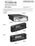
TK-890 or TK-890(B) with KCH-10
Panel assy
(A62-0606-13)
Cabinet (Upper)
(A01-2161-02)
Cabinet (Lower)
(A01-2162-02)
Knob
(K29-4664-04) x 2
KCH-11
Knob
(K29-4664-04) x 2
Panel assy
(A62-0607-13)
Cabinet (Upper)
(A01-2163-01)
TK-890H(B)
Cabinet (Lower)
(A01-2164-01)
TK-890/(B)/H(B)
CONTENTS / GENERAL
GENERAL ......................................................................................................................... 2
SYSTEM SET-UP ............................................................................................................. 4
OPERATING FEATURES ................................................................................................. 5
INSTALLATION .............................................................................................................. 16
DISASSEMBLY FOR REPAIR ........................................................................................ 22
CIRCUIT DESCRIPTION ................................................................................................. 26
SEMICONDUCTOR DATA ............................................................................................. 32
DESCRIPTION OF COMPONENTS ............................................................................... 36
PARTS LIST .................................................................................................................... 39
EXPLODED VIEW .......................................................................................................... 58
PACKING ........................................................................................................................ 62
ADJUSTMENT ............................................................................................................... 66
TERMINAL FUNCTION ................................................................................................. 76
WIRING .......................................................................................................................... 79
PC BOARD VIEWS / CIRCUIT DIAGRAMS
DISPLAY UNIT (X54-3190-20) : KCH-10 .................................................................. 81
DISPLAY UNIT (X54-3200-20) : KCH-11 .................................................................. 83
CONTROL UNIT (X57-5620-XX) (B/3) ..................................................................... 89
FINAL UNIT (X57-5620-XX) (C/3) : TK-890/(B) ....................................................... 99
TX-RX UNIT (X57-5620-XX) (A/3) ......................................................................... 103
FINAL UNIT (X45-3570-10) : TK-890H(B) .............................................................. 115
BLOCK DIAGRAM ........................................................................................................ 119
SPECIFICATIONS ......................................................................................................... 121
GENERAL
INTRODUCTION
PERSONNEL SAFETY
SCOPE OF THIS MANUAL
The following precautions are recommended for personnel safety :
• DO NOT transmit if someone is within two feet (0.6
meter) of the antenna.
• DO NOT transmit until all RF connectors are secure and
any open connectors are properly terminated.
• SHUT OFF this equipment when near electrical blasting
caps or while in an explosive atmosphere.
• All equipment should be properly grounded before
power-up for safe operation.
• This equipment should be serviced by only qualified technicians.
This manual is intended for use by experienced technicians familiar with similar types of commercial grade communications equipment. It contains all required service information for the equipment and is current as of this publication date. Changes which may occur after publication are
covered by either Service Bulletins or Manual Revisions,
which are issued as required.
ORDERING REPLACEMENT PARTS
When ordering replacement parts or equipment information, the full part identification number should be included.
This applies to all parts : components, kits, and chassis. If
the part number is not known, include the chassis or kit
number of which it is a part and a sufficient description of
the required component, for proper identification.
2
TK-890/(B)/H(B)
GENERAL
PRE-INSTALLATION CONSIDERATIONS
1. UNPACKING
Unpack the radio from its shipping container and check
for accessory items. If any item is missing, please contact
KENWOOD immediately.
2. LICENSING REQUIREMENTS
Federal regulations require a station license for each radio installation (mobile or base) be obtained by the equipment owner. The licensee is responsible for ensuring transmitter power, frequency, and deviation are within the limits
permitted by the station license.
Transmitter adjustments may be performed only by a licensed technician holding an FCC first, second or general
class commercial radiotelephone operator’s license. There
is no license required to install or operate the radio.
3. PRE-INSTALLATION CHECKOUT
3-1. Introduction
Each radio is adjusted and tested before shipment. However, it is recommended that receiver and transmitter operation be checked for proper operation before installation.
3-2. Testing
The radio should be tested complete with all cabling and
accessories as they will be connected in the final installation. Transmitter frequency, deviation, and power output
should be checked, as should receiver sensitivity, squelch
operation, and audio output. QT equipment operation
should be verified.
4. PLANNING THE INSTALLATION
4-1. General
Inspect the vehicle and determine how and where the
radio antenna and accessories will be mounted.
Plan cable runs for protection against pinching or crushing wiring, and radio installation to prevent overheating.
4-2. Antenna
The favored location for an antenna is in the center of a
large, flat conductive area, usually at the roof center. The
trunk lid is preferred, bond the trunk lid and vehicle chassis
using ground straps to ensure the lid is at chassis ground.
4-3. Radio
The universal mount bracket allows the radio to be
mounted in a variety of ways. Be sure the mounting surface
is adequate to support the radio’s weight. Allow sufficient
space around the radio for air cooling. Position the radio
close enough to the vehicle operator to permit easy access
to the controls when driving.
4-4. DC Power and wiring
1. This radio may be installed in negative ground electrical
systems only. Reverse polarity will cause the cable fuse
to blow. Check the vehicle ground polarity before installation to prevent wasted time and effort.
2. Connect the positive power lead directly to the vehicle
battery positive terminal. Connecting the Positive lead to
any other positive voltage source in the vehicle is not recommended.
3. The cable provided with the radio is sufficient to handle
the maximum radio current demand. If the cable must be
extended, be sure the additional wire is sufficient for the
current to be carried and length of the added lead.
5. INSTALLATION PLANNING – CONTROL STATIONS
5-1. Antenna system
Control station. The antenna system selection depends
on many factors and is beyond the scope of this manual.
Your KENWOOD dealer can help you select an antenna system that will best serve your particular needs.
5-2. Radio location
Select a convenient location for your control station radio
which is as close as practical to the antenna cable entry
point. Secondly, use your system’s power supply (which
supplies the voltage and current required for your system).
Make sure sufficient air can flow around the radio and
power supply to allow adequate cooling.
SERVICE
This radio is designed for easy servicing. Refer to the
schematic diagrams, printed circuit board views, and alignment procedures contained in this manual.
3
TK-890/(B)/H(B)
SYSTEM SET-UP
Before Reading About System Set-up
The TK-890(B)/H(B) is a transceiver main unit (without a
panel or speaker) that you complete by adding options.
The options are classified into three types according to
operation and function.
1. Install the front panel kit (controller) directly on a radio to
operate it. (Form : Radio + KCH-10/11)
2. Remotely control one radio with one controller. (Form
: Radio + KRK-5 + KCH-10/11 + KCT-22M/M2/M3)
3. Remotely control one radio with two controllers. (Form
: Radio + KRK-6DH + KCH-10/11 (two) + KCT-22M/M2/
M3 (two))
4. Remotely control two radios with one controller. (Form
: Radios (two) + KRK-7DB + KCH-10/11 + KCT-22M/M2/
M3)
5. Remotely control two radios with two controllers. (Form
: Radio (two) + KRK-8DBH + KCH-10/11 (two) + KCT22M/M2/M3 (two))
Frequency range RF power
40W
450~490MHz
480~512MHz
40W
403~430MHz
40W
100W
450~470MHz
75W
470~480MHz
Merchandise received
License and frequency allocated by FCC
Choose the type of transceiver
Type
TK-890/(B) F1
TK-890(B) F2
TK-890(B) F3
TK-890H(B) F1
TK-890/(B), TK-890H(B) (Radio 1)
TK-890(B) or TK-890H(B) is complete by combining
options with only the transceiver body (without panel)
Are you using two radios with two controllers?
YES
Are you using two radios with one controller?
TK-890 : Contain (KCH-10)
Are you using the remote kit?
NO
See
page 16
See page 16
KCH-10 (Basic model)
Front panel kit
YES
*See Remote
kit service
manual
KCH-11 (Full featured
model) Front panel kit
YES
Are you using one radio with two controllers?
YES
Are you using one radio
with one controller?
YES
KRK-5
Single control head kit
Are you using the printed keytops?
See page 16
KRK-6DH
Dual control head kit
KRK-7DB
Dual band remote kit
KRK-8DBH
Dual band dual control head kit
NO
or
YES
KCH-10
or
KCH-11
Supplied accessory knob
KCH-10
+
KCH-10
or
or
KCH-10
+
KCH-11
KCH-11
+
KCH-11
KCH-10
or
KCH-11
KCH-10
+
KCH-10
or
KCH-10
+
KCH-11
KCH-11
+
KCH-11
KCT-22M/M2/M3 *See Remote kit
service manual
Control cable
See page 17
Are you using the voice scrambler?
YES
Modified of control unit
NO
Transceiver programming (option)
Are you using the external speaker?
See page 13
A personal computer (IBM PC or compatible), programming interface (KPG-43),
and programming software (KPG-44D) are required for programming.
(The frequency and signalling data are programmed for the transceiver.)
YES
KES-4 (EXT. SP)
See page 18
NO
KCT-23 (DC cable)
Are you using the ignition sense cable?
See Installation manual
KCT-23 M,M3 : TK-890/(B), KCT-23 M2,M4 : TK-890H(B)
YES
KCT-18
See page 18
NO
Delivery
*Service manual parts No. list
Model
4
Parts No.
KRK-5/6DH
B51-8445-00
KRK-7DB/8DBH
B51-8452-00
TK-890/(B)/H(B)
OPERATING FEATURES
(1) POWER Switch
Press to turn the power ON and OFF.
(2) TX/BUSY Indicator
The TX Indicator (Red LED) shows that you are transmitting.
The BUSY Indicator (Green LED) shows that the channel
is in use.
(3) Microphone Connector
(4) Volume Knob
To increase the volume level, turn clockwise (CW).
To decrease the volume level, turn counterclockwise
(CCW).
(5) UP/DOWN Knob
The function of this Knob can be programmed by the
FPU.
1. Controls and Functions
1-1. Basic Function Panel
(1)
(6) (7)
(19)
POWER
GRP
TX BUSY
VOL
(2) (3)
CH
(4)
(5)
(10)
(11)
(12)
(13)
(14)
Function
(31)
(29)
(24) (26) (28)
(25) (27)
(20) (21) (22)(23)
Description
Note
Channel
Channel selector.
Default
UP/DOWN
To increase the channel, turn CW.
setting.
To decrease the channel, turn CCW.
Group
Group selector.
UP/DOWN
To increase the group, turn CW.
To decrease the group, turn CCW.
(32)
(6) GR UP Key, (7) GR DW Key, (8) MON Key, (9) SCN Key,
(10)~(18) PF1-9 Key
The function of these Keys can be programmed by the
FPU.
(30)
1-2. Full Function Panel
(1)
Function
(6) (7)
(19)
(9) (8)(17) (15) (16)
(18)
Description
No
No function.
Function
POWER
MON
CALL
MON
SCAN
SP
OPT
A
B
C
OST
GRP
SCN
Note
[ ] : Key top name
Default setting
of PF1~9.
Monitor
If [MON] is pressed once while
Default setting
[MON]
the RADIO is waiting for reception, of MON. (Full
TX BUSY
all signalling* squelch is canceled.
VOL
function panel)
CH
If [MON] is held down for 2 seconds, all singalling;
(2) (3)
(29) (31)
(4)
(20)
CALL
(5)
(21)
MON
(10)
(11)
(22) (23)
SCAN
SP
(12)
(13)
(14)
(26)
(24) (25) (27) (28)(30)
OPT
A
B
C
OST
noise squelch is canceled and the
QT/DQT &
audio is unmuted.
2 TONE/DTMF
Scan
Start and stop the scanning
Default setting
[SCN]
sequence.
of SCN. (Full
function panel)
Public
The RADIO works as a PUBLIC
Address [PA]
ADDRESS amplifier.
Horn Alert
When the RADIO receives a
[HA]
the optional signalling calls that
are assigned to the channel, the
HA relay turns on.
(32)
Talk Around
Use this function to communicate
[TA]
with other operators directry,
without using a repeater.
Intercom
Use this function to communicate Dual HEAD
[IC]
between the HEAD1 and HEAD2
configuration
operator without transmitting.
only.
5
TK-890/(B)/H(B)
OPERATING FEATURES
Function
Description
Note
[ ] : Key top name
Function
Description
Note
[ ] : Key top name
Channel
Switches the display between
Speaker 1-2 Each speaker audio can be
Dual HEAD
Name [AN]
Group-Channel No. and Group
Mute [SPM] manually disabled from the
configuration
other control head.
Channel UP If [
Internal/
Internal speaker and PA speaker.
[
>
Switch the audio output between
]
>
channel name.
Speaker
increases by one step.
If [
than 2 seconds
If [
DOWN [ ]
decreases by one step.
to toggle a
If [
Group DEL
and ADD.
<
Channel
] is pressed once, the channel
<
setting of each channel or group. [D/A] for more
] is held down for 1 second,
the channel decreases continuously.
Group UP
If [
[
increases by one step.
] is pressed once, the group
Squelch
Press to enter Squelch Level Adjust
Level
Mode. The Squelch level can be
If [
[SQL]
adjusted by using the UP/DOWN
the group increases continuously.
If [
DOWN [ ]
decreases by one step.
Operator
Select signalling from the pre-
Selectable
programmed QT/DQT list.
] is held down for 1 second,
the group decreases continuously.
Mobile Relay The RADIO works as a repeater. Dual BAND
Tone [OST]
Station [RPT]
The optional board on and off.
[OPT]
configuration
Install the
Scrambler board.
AUX A [AUXA] Turns AUX A port on and off.
AUX B [AUXB]
] is pressed once, the group
<
If [
<
Group
channel Up/Down key or Group
<
Knob, or the preprogrammed
Up/Down key.
Scrambler
] is held down for 1 second,
>
>
]
>
Add [D/A]
] is held down for 1 second,
the channel increases continuously.
<
Changes the Scan DELETE/ADD Press and hold
>
External [SP]
Delete/
only.
] is pressed once, the channel
only.
Emergency To start an Emergency Call,
This function
Call [EMG]
needs the ANI
press [EMG].
Turns AUX B port on and off.
board.
AUX C [AUXC] Turns AUX C port on and off.
Home Channel
(19) LCD Display
Switches to the pre-programmed
(Fixed) [HC] Home Channel.
Home Channel
Description
When pressed once, switches to
(20) CALL
(Toggle) [HC] the Home Channel. Press again
to returns to the previous channel.
CH1 Direct
by proper Optional Signalling
has been set
(DTMF or 2Tone).
“AND”, CALL
Switches to the GR1-CH1 directry.
lights after
[CH1]
CH2 Direct
transmitting.
Switches to the GR1-CH2 directry.
(21) MON
Switches to the GR1-CH3 directry.
(22) SCN
[CH2]
CH3 Direct
Switches to the GR1-CH4 directry.
(23) SP
6
Lights when “PA speaker” is
selected for audio output.
Switches to the GR1-CH5 directry.
(24) OPT
[CH5]
Channel
Indicates when scan mode is
enabled.
[CH4]
CH5 Direct
Lights when [MON] is pressed.
Signalling squelch is disabled.
[CH3]
CH4 Direct
Note
Flashes when the RADIO is called If Signalling
When pressed once, switches to
The [RCL] Key
Recall [RCL] the last called channel. Press again
works in Scan
(25) A
Lights when the optional board*, Optional
that is installed inside the RADIO,
Board :
is enabled.
· Scrambler
Lights when [AUXA] is pressed.
to return to the previous channel. Mode only.
The PF Port that is programmed
Dimmer
Use this function to adjust the LCD
with “AUX A” is ON.
[DIM]
backlight brightness, Key backlight,
(26) B
Lights when [AUXB] is pressed.
TX/BUSY LED, and DTMF Mic Key
The PF Port that is programmed
backlight ON/OFF.
with “AUX B” is ON.
TK-890/(B)/H(B)
OPERATING FEATURES
Description
(27) C
Note
Lights when [AUXC] is pressed.
The PF Port that is programmed
with “AUX C” is ON.
(28) OST
Lights when [OST] is pressed,
Operator Selectable Tone is
enabled.
(29) ▼
If the selected group is in the
(Group
multi group scan sequence,
Add Status) the indicator appears at the
group.
(30) ▼
If the selected channel is in the
(Channel
scan sequence, the indicator
Add Status) appears at the channel.
(31)
Displays the channel status.
• BASIC
P1 : Lights when a PRIORITY 1
FUNCTION channel is shown on the display.
PANEL 7
P2 : Lights when a PRIORITY 2
SEGMENT
channel is shown on the display.
display
PP : Lights when a PRIORITY 1
• FULL
& 2 channel is shown on the display.
2. Receive
(1) To turn on the RADIO:
Press the Power Switch. The display and graphics illuminate to indicate the RADIO is ON.
(2) To adjust the volume level:
Turn the Volume Knob CW to increase the volume level.
Turn the Volume Knob CCW to decrease the volume
level.
(3) To select a Group:
Select a Group by rotating the UP/DOWN Knob which
has been programmed with “Group UP/DOWN” or by
pressing the Keys which have been programmed with
“Group UP” and “Group DOWN”.
If the “Channel Tracking Function” is enabled, the channel number will not change.
(4) To Select a Channel:
Select a Channel by rotaing the UP/DOWN Knob which
has been programmed with “Channel UP/DOWN” or by
pressing the keys which have been programmed with
“Channel UP” and “Channel DOWN”.
(5) To enter carrier squelch mode:
If you want to monitor a channel, press [MON] Key. If the
“OFF HOOK Decode” function has been disabled, you
can also enter monitor mode by taking the microphone
off HOOK.
FUNCTION HC : Lights when a Home
PANEL
Channel is selected by [HC] key.
DOT
TA : Lights when the RADIO is
MATRIX (S) in Talk Around mode.
display
RCL : Lights when recall
channel is selected by [RCL] key.
R1-R15 : Lights when remote
channel is selected by PF port.
(32)
Displays the operating Group-
• BASIC
Channel number (Channel display),
FUNCTION or name (Alphanumeric display)
PANEL 13
programmed by the FPU. Also
SEGMENT
displays the status of some
display
features.
• FULL
FUNCTION
PANEL DOT
3. Transmit
(1) Normal ON HOOK Scan Mode
First, lift the microphone from the HOOK. The scanning
stops temporarily and the OFF HOOK revert channel is
displayed. Listen for a few seconds to make certain the
channel is not being used.
OFF HOOK Scan MODE
If scanning, pressing the PTT switch will stop the RADIO
on the OFF HOOK revert channel and begin transmission immediately.
Not Scan Mode
Pressing PTT starts transmission at the selected channel.
(2) Press PTT and start speaking. For best results, hold the
microphone 1 to 1.5 inches from your mouth. Release
PTT when your message is complete. Listen for a response.
(3) When your conversation is finished, replace the microphone on its hook.
MATRIX (L)
display
4. Scan Operation
4-1. General
1-3. Microphone
Press PTT (Push To Talk) to transmit, then speak into the
microphone.
There are two “Mic HOOK” scan modes in which the
RADIO can be programmed to operate.
• ON HOOK Scan
Normal method of scanning that requires the microphone
to be ON HOOK (hanged on the Mic Hanger) to initiate
scan.
• OFF HOOK Scan
The microphone does not have to be ON HOOK to initiate
scan or to scan channels.
7
TK-890/(B)/H(B)
OPERATING FEATURES
(1) The scan feature is initiated by pressing the [SCN] Key.
(2) A single confirmation tone sounds, and scanning starts. If
there is only one or no added channels, an error tone will
sound and scanning will not start.
(3) The display shows “SCN” icon, and “SCAN” or the OFF
HOOK Revert Channel Number (FPU setting).
(4) If the RADIO receives a proper signal while scanning,
scanning stops temporarily, audio is unmuted, and the
channel number or name is displayed.
If either “Priority1” or “Priority2” is programmed and
scanning stops at a Normal Channel by receiving a signal,
the RADIO watches for a signal on the Priority Channel
periodically. When a signal exists on the Priority Channel,
the channel will change from the Normal Channel to Priority Channel.
If both “Priority1” and “Priority2” are programmed and
scanning stops at the Priority2 Channel by receiving a signal, the RADIO watches a signal on the Priority1 Channel
periodically. When a signal exists on the Priority1 Channel, the channel will change from the Priority2 Channel to
the Priority1 Channel.
If there is no Priority Channel programmed, the scanning
stops at a channel and receives only that channel.
(5) If the [SCN] Key pressed again, Scan Mode ends at the
revert channel, and two confirmation tones sound.
4-2. To Delete Undesired Channels
To temporarily delete undesirable channels, press [D/A]
Key while the channel is displayed, and scanning resumes.
(To temporarily delete Priority Channel 1 or 2, set the “Priority Temporary D/A” function to “YES”.)
You can’t delete a channel in Scan Mode under the following conditions:
• Priority Scan
There is only channel beside the Priority Channel in the
scan sequence.
• Non-priority Scan
There are only 2 channels in the scan sequence. To restore the original scan sequence, either turn scan off and
on or turn the RADIO off and on.
4-3. To Enter Carrier Squelch Scan While Scan is On
If you have pressed the [MON] Key, the MON indicator is
turned on and the RADIO operates in carrier squelch scan.
5. Adding Channels and Groups to the
Scan Sequence
(1) Channels
To add the currently displayed channel to the scan sequence, press [D/A] Key. The CH ADD indicator (▼)
lights, and the channel is added to the scan sequence.
(2) Groups
To add the currently displayed group of channels to the
scan sequence, hold down the [D/A] Key for 2 seconds.
The GR ADD indicator (▼) lights, and the group is added
to the scan sequence.
8
6. Deleting Channels and Groups from the
Scan Sequence
(1) Channels
To delete a channel from the scan sequence press [D/A]
Key. The CH ADD indicator (▼) goes off, and the channel
is deleted from the scan sequence.
(2) Groups
To delete the currently displayed group of channels from
the scan sequence, hold down [D/A] Key for 2 seconds.
The GR ADD indicator (▼) goes off, and all the channels
in the group are deleted from the multi group scan sequence.
7. Operator Selectable Priority
(1) Operator Selectable Priority1
If Priority1 has been set to “Operator Selectable”, you
can set the currently displayed channel as Priority1.
To set the currently displayed channel as Priority1, hold
down the [SCN] Key and press the [MON] Key three
times.
(2) Operator Selectable Priority2
If Priority2 has been set to “Operator Selectable” you
can set the currently displayed channel as Priority2.
To set the currently displayed channel as Priority2, hold
down the [SCN] Key and press the [MON] Key twice.
8. Talk Around (TA)
Talk Around is useful when you are close to other mobiles you want to talk to, or are outside the range of your
repeater system.
Press the [TA] Key. A confirmation tone sounds, and
“TA” (BASIC Panel : 7 segment, FULL Panel : DOT MATRIX
(S)) is displayed. You can communicate without using a repeater.
To use a repeater, press [TA] again. A confirmation tone
sounds, and “TA” goes off.
9. Horn Alert (HA)
If you are called from the base station using 2Tone/DTMF
while you are away from your transceiver, you will be
alerted by the vehicle horn or some other type of external
alert. To turn the horn alert function on, press the [HA] Key.
A confirmation tone sounds, and the display shows HORN
ALERT (or HA).
If [HA] is pressed again, the horn alert function is turned
off.
TK-890/(B)/H(B)
OPERATING FEATURES
10. Public Address (PA)
CASE1 : HC has been set as “HC (Fixed)”
Public Address amplifies the microphone audio, and outputs it through a PA speaker. PA is activated by pressing the
[PA] Key. A confirmation tone sounds, and the display
shows PUBLIC ADDRESS (or PA). PA can be activated at
anytime (scanning or non-scanning).
The RADIO continues to scan & receive calls while in PA
mode. Pressing PTT activates PA, and will override an incoming call at anytime ; however, no RADIO transmission
takes place. If [PA] is pressed again, a confirmation tone will
sound, the display will return to the normal channel or
SCAN display, and the PA function will turn off.
Non-Scan
12. Channel Name (AN)
This function switches the 13-segment display (BASIC
Panel) or DOT MATRIX (L) display (FULL Panel) between alphanumeric and Group-Channel number.
If you want to change from alphanumeric display to channel display, press [AN] Key. A confirmation tone sounds, and
the alphanumeric display changes to the channel display.
If [AN] is pressed again, a confirmation tone sounds, and
the channel display changes back to the alphanumeric display.
stopping
press [HC] once
Change to Home Channel
press [HC] again
No effect
CASE2 : HC has been set as “HC (Toggle)”
Non-Scan
Scanning
Scan
Mode
temporary
stopping
press [HC] once
Change to Home Channel
press [HC] again
Return to
Change to
Return to
current channel
Revert Channel
current channel
15. Squelch Level (SQL)
This function allows the radio operator to manually adjust
the squelch threshold in 16 steps (Level 0~15) via the front
panel controls. To adjust the squelch level:
(1) Press the [SQL] Key. A confirmation tone sounds, and
the RADIO enters Squelch Level Adjust Mode. In this
mode, all signallings are canceled and audio is unmuted.
The display shows SQUELCH XX (or SQL XX). (XX=
squelch level)
(2) Change the squelch level by pressing [ ] and [ ] Keys,
or rotating the UP/DOWN Knob.
(3) Press [SQL] again. A confirmation tone sounds, the display returns to the normal channel, the level setting is
memorized, and Squelch Level Adjust Mode will turn off.
<
SP amplifies the received audio from the RADIO and outputs it through a PA speaker. SP is activated by pressing the
[SP] Key. A confirmation tone sounds and the SP icon is displayed. SP can be activated at anytime (scanning or nonscanning).
The RADIO transmits and operates normally while SP is
activated, but all received calls will be output through the PA
speaker. If [SP] is pressed again, a confirmation tone
sounds, the SP icon goes off and the SP function will turn
off.
Scan
temporary
>
11. Speaker Internal/External (SP)
Scanning
Mode
* This feature can be initiated when the RADIO is not in
scanning mode.
16. Operator Selectable Tone (OST)
(1) Press the [OST] Key. A confirmation tone sounds, and
the display shows the OST Name which is memorized in
the channel for 2 seconds. The “OST” icon lights, and
OST is enabled.
Press [OST] again, and the OST icon goes off and OST is
disabled.
(2) When the [OST] Key is held down, a confirmation tone
sounds and the RADIO enters OST Select Mode.
(3) Select the Dec/Enc pair by pressing the [ ] and [ ]
Keys, or rotating the UP/DOWN Knob. The display shows
TONE XX (XX=Dec/Enc pair number) or the OST Name.
(4) Press [OST] again, a confirmation tone sounds, the display returns to the normal channel, the pair is memorized
and OST Mode will turn off.
>
Intercom (IC) allows one control head operator to talk to
the another control head operator. IC mode is activated by
pressing the [IC] Key. A confirmation tone sounds and
the display shows INTERCOM. IC can be activated at anytime (scanning or non-scanning).
The RADIO continues to scan & receive calls while in IC
mode. Pressing PTT activates IC and will override an incoming call at anytime ; however, no RADIO transmission takes
place. If [IC] is pressed again, a confirmation tone sounds,
the display returns to the normal channel or SCAN display,
and the IC function will turn off.
This function allows the radio operator to change the preset decode QT/DQT, encode QT/DQT. You can select Dec/
Enc OFF or from up to 16 decode/encode pairs (Pair No.
1~16) programmed by the FPU. To select the Dec/Enc pairs:
14. Home Channel (HC)
This feature allows the radio operator to immediately select a pre-determined “Home Channel” by pressing the [HC]
Key. HC can be activated as follows.
<
13. Intercom (IC) ; Dual Head Configuration only
* You can select a Dec/Enc pair on each channel.
9
TK-890/(B)/H(B)
OPERATING FEATURES
17. Option Board (OPT)
<
>
If an optional Scrambler board has been installed in the
RADIO, Scrambler is activated by pressing the [OPT] Key. A
confirmation tone sounds, and the OPT icon is displayed. If
[OPT] is pressed again, a confirmation tone sounds, the OPT
icon goes off and the Scrambler will turn off.
If [OPT] is held down, the RADIO enters SCR Code Set
Mode. A confirmation tone sounds, and the display shows
CODE XX (XX=SCR Code). Change the SCR Code by pressing the [ ] and [ ] Keys, or rotating the UP/DOWN Knob.
Press [OPT] again, a confirmation tone sounds, the display returns to channel (SCR is ON), the SCR Code setting is
memorized, then SCR Code Set Mode will turn off.
18. AUX A, AUX B, AUX C
This function switches the accessory PF Output ports
which have been programmed with AUX A, AUX B and AUX
C.
Press [AUXA] Key. A confirmation tone sounds, the A
icon is displayed, and the AUX A Port is switched on (Low
level). If [AUXA] is pressed again, a confirmation tone
sounds, the A icon goes off and the AUX A Port is switched
off (open collector).
In the same way, [AUXB] Key controls the AUX B Port,
and [AUXC] Key controls the AUX C Port.
Display
Default
Press [DIM]
TX/BUSY
Panel Keys Microphone
backlight
LED
backlight
Keys backlight
High
High
High
High
Medium
↓
↓
↓
once
Press again
Low
↓
↓
↓
Press again
OFF
OFF
OFF
OFF
Press again
return to
return to
return to
return to
High
High
High
High
* The brightness setting is memorized.
22. Speaker 1-2 Mute (SPM)
; Dual Head Configuration only
This feature allows the radio operator to manually disable
the speaker audio of another control head.
Press the [SPM] Key, a confirmation tone sounds, and
the other head speaker is muted. Both head displays shows
X MUTE (X=Muted HEAD number).
This muted condition is canceled by both head keys without PTT and Mic HOOK which is connected to Un-muted
head.
23. Mobile Relay Station (RPT)
19. Direct Channel Access
This feature allows the radio operator to immediately select CHANNELs 1~5 which are contained in GROUP 1. To
select GR1-CH1, press [CH1]. To select GR1-CH2~5, press
[CH2] ~ [CH5],
20. Channel Recall (RCL)
This feature is enabled in scan mode.
This feature allows the radio operator to immediately access the last called (Unmuted) channel by pressing [RCL].
The 3-digit display shows “RCL”. Press [RCL] again, and the
radio returns to the previous channel.
21. Dimmer (DIM)
To adjust the brightness of the display backlight, TX/
BUSY LED, panel Keys backlight and microphone keys backlight, press the [DIM] Key.
[DIM] controls the brightness at the same time as follows.
10
; Dual Band Configuration only
This function allows the radio operator to use the RADIO
as a repeater.
(1) Both “Repeater Channel 1” and “Repeater Channel 2”
must be pre-programmed by the FPU. Each channels
must be on diferent bands.
(2) Press the [RPT] Key, then both the VHF and UHF units
move to the repeater channel, and enter Repeater mode.
Displays of both heads show “REPEATER”.
(3) If one unit receives a proper signal, the other unit will
start transmitting (repeating).
(4) If the signal stops, the repeat action will stop. If one of
the units detects another signal, the repeat action will restart.
(5) Press [RPT] again, both units return to their previous
channels, and exit the Repeater mode. However, during
the repeating mode, pressing [RPT] has no effect.
24. Emargency Call (EMG)
If the [EMG] Key is held down, the RADIO enters the
Emergency Mode. In the Emergency Mode, the channel
changes to the “Emergency Channel (set by the FPU)” internally. The display depends on “Emergency Channel Display” setting, and the Emergency Call (None, DTMF, MSK or
ANI board) is transmitted.
If “ANI Board” is selected for the Emergency Type, turn
the transceiver off, then turn it on again to recover “Normal
Mode”.
If “ANI Board” is not selected for the Emergency Type,
press and hold [EMG] key to recover “Normal Mode”.
TK-890/(B)/H(B)
OPERATING FEATURES
2Tone signalling opens the squelch only when the RADIO receives a proper 2Tone code that is the same as the
pre-programmed 2Tone for the channel. When the RADIO
receives a 2Tone code, the CALL icon flashes.
If Transpond has been programmed, the RADIO will return an acknowledgment signal automatically after receiving
the 2Tone code.
If Call Alert has been programmed, an Alert Tone sounds
after receiving a 2Tone code. You can configure “Normal”
(an alert tone beeps once) or “Continuous” (an alert tone
beeps every 5 seconds) for the Call Alert. Unmute condition
is canceled and the CALL icon goes off when ; (1) pressing
the [MON] Key, (2) hanging the microphone on its hook, (3)
muting continues for 10 seconds. (If “Auto Reset” has been
programmed)
27. DTMF Signalling
29-1. AND
The audio is unmuted when the RADIO receives the correct QT/DQT and 2Tone/DTMF. After transmitting, 2Tone/
DTMF will be canceled.
29-2. OR
The audio is unmuted when the RADIO receives the correct QT/DQT. 2Tone/DTMF is used just as an individual call
or group call.
30. Off Hook Decode
If the OFF HOOK Decode function has been enabled, removing and replacing the microphone on the HOOK has no
effect for decoding QT/DQT and 2Tone/DTMF.
31. TX Audio Monitor
; Dual Head Configuration only
This function allows the radio operator to hear another
operator’s voice which is transmitted through another control head.
If the TX Audio Monitor function is set to “w/Talk Interrupt” and one operator is transmitting, the other operator’s
control head displays “INTERCOM” and he/she can speak
to the transmitting control head by pressing PTT.
32. Roll Over/Dead End
32-1. Roll Over
When [ ] (CH UP) is pressed, or the CH UP/DOWN Knob
is turned CW from the Maximum channel, the channel
changes to the Minimum channel.
When [ ] (CH DOWN) is pressed, or the CH UP/DOWN
Knob is turned CCW from the Minimum channel, the channel changes to the Maximum channel.
32-2. Dead End
When [ ] (GR UP) is pressed, or the GR UP/DOWN Knob
is turned CW from the Maximum group, the group doesn’t
change.
When [ ] (CH UP) is pressed, or the CH UP/DOWN Knob
is turned CW from the Maximum channel, the channel
doesn’t change.
When [ ] (GR DOWN) is pressed, or the GR UP/DOWN
Knob is turned CCW from the Minimum group, the group
doesn’t change.
When [ ] (CH DOWN) is pressed, or the CH UP/DOWN
Knob is turned CCW from the Minimum channel, the channel doesn’t change.
The Time Out Timer function interrupts continuous transmission after a specified time elapses.
Holding down PTT for longer than the programmed time
causes the RADIO to stop transmitting and sound a warning
tone. To stop the warning tone, release PTT.
<
28. Time Out Timer
(Possible to configure to each group)
<
>
DTMF Signalling opens the squelch only when the RADIO receives a proper DTMF code that is the same as the
pre-programmed “Primary Code (Individual ; 1~7digits)” or
“Secondary Code (Group ; 1~7digits)”. When the RADIO receives a correct code, the CALL icon flashes.
If Transpond has been programmed, the RADIO will return an acknowledgment signal automatically after receiving
the DTMF code.
If Call Alert has been programmed, an Alert Tone sounds
after receiving a DTMF code. You can configure “Normal”
(an alert tone beeps once) or “Continuous” (an alert tone
beeps every 5 seconds) for the Call Alert. Unmute condition
is canceled and the CALL icon goes off when ; (1) pressing
the [MON] Key, (2) hanging the microphone on its hook, (3)
muting continues for 10 seconds (If “Auto Reset” has been
programmed), and (4) receiving reset code. (Primary code +
“#” or secondary code + “#”)
The RADIO will be unmuted with a combination of QT/
DQT and 2Tone/DTMF. The AND/OR setting works as follows.
>
26. 2Tone Signalling
29. Signalling AND/OR
(Possible to configure to each group)
<
The Busy Channel Lockout function prevents
interferance with other stations that may be using the same
channel.
While the selected channel is in use, pressing PTT
causes the RADIO to sound a warning tone, and transmission is inhibited. To stop the warning tone, release PTT.
If BCL Override has been enabled, pressing PTT within
500msec again will cancel BCL, and transmission is enabled.
>
25. Busy Channel Lockout (BCL), BCL Override
11
TK-890/(B)/H(B)
OPERATING FEATURES
36-2. PF Output Port
33. Minimum Volume
When the Volume Knob is adjusted fully counterclockwise, the audio level is set to the Minimum Volume level
which is programmed by the FPU.
AUX A
Pressing [AUXA] once → Low, Pressing [A]
AUX B
Pressing [AUXB] once → Low, Pressing [B]
34. Dead Beat Disable (DBD)
AUX C
Pressing [AUXC] once → Low, Pressing [C]
[AUXA] again → OPEN-COLLECTOR
[AUXB] again → OPEN-COLLECTOR
If the RADIO receives a DBD Code (1~7digits), the RADIO returns an acknowledgment signal automatically, and
transmission is disabled. This TX INHIBIT condition is
memorized.
If the RADIO receives a DBD Reset Code (DBD Code +
#), the RADIO returns an acknowledgment signal automatically, and transmission is Enabled.
35. ANI Board
The ANI board contains functions which you can use. To
use the function, you select that function on the ANI board.
36. Accessory Programmable Function
Port (PF Port)
The RADIO has 13 PF Ports.
HEAD (12 pin) : PF Input Port 2, PF Output Port 2
DECK (Dsub 25 pin) : PF Input Port 5, PF Output Port 4
Each Port can be programmed with a function from next
Table.
36-1. PF Input Port
External HOOK
Receiving correct QT/DQT → Low, Not receiving correct QT/DQT → OPEN-COLLECTOR
COR
BUSY → Low, Not BUSY → OPEN-COLLECTOR
37. Timed Power Off
This function works as “Automatic Power Switch Off”.
Timed Power Off timer starts from the ignition-off. After
the timer expires, the RADIO will automatically turn off. The
timer will be reset if the ignition is turned on and off.
This function requires ignition-sense. Connect the ignition-line to the 9-pin connector which is located at the rear of
the RADIO.
After the timer expires, you can turn the transceiver on
again with 2 methods below.
1) Timed power off function (Default)
Press the power switch.
2) Ignition function & Timed power off function
Turn the ignition on.
38. Emergency
• Active tome
Automatic transmission period in the emergency mode.
Open → OFF HOOK, Low → ON HOOK
1~15. If CH Select A~D are set “H” or “Open”,
CH Select C
the channel is selected by using the [
CH Select D
keys or UP/DOWN Knob. (User Channel)
• Duration of Locator Tone 1
External PTT
Open → PTT OFF, Low → PTT ON
Scan
Open → Scan OFF, Low → Scan ON
Duration of an alert tone before the automatic transmission is performed.
Home Channel
Open → Current Channel, Low → Home Channel
• Duration of Locator Tone 2
Light Sense
Open → LCD Backlight is controlled by [DIM],
Duration of an alert tone after the automatic transmission
is performed.
]/[
<
The Channel changes to Remote Channel
CH Select B
>
CH Select A
Open → Repeater inactive, Low → Repeater Active
* Dual BAND configuration only
External Monitor
Open → Monitor OFF, Low → Monitor ON
• Interval Time
Interval time between the automatic tansmissions.
]
Low → LCD Backlight is set “Low”
Repeater SW
12
[AUXC] again → OPEN-COLLECTOR
TOR
• Emergency Channel Display
Setting for the display in the emergency mode.
The transceiver can be programmed to display “EMERGENCY” channel name when it is in emergency mode.
If you set to “off” by KPG-44D the transceiver shows
selected group/channel/status before entering to the emergency mode however the transceiver is in an emergency
mode.
TK-890/(B)/H(B)
OPERATING FEATURES
• Emergency Mode Type
Speaker mute on or off in the emergency mode.
41-2. Programming Interface Cable KPG-43 Description
Select an Emergency code format from DTMF, MSK, ANI
board or OFF (Disabled).
The KPG-43 is required to interface TK-890 to the computer. It has a circuit in its D-sub 25 pin connector case that
converts RS-232C logic level to TTL level.
KPG-43 is used to connect between TK-890 microphone
connector and RS-232C serial port of computer.
• Emergency DTMF ID
41-3. Programming Software KPG-44D Description
The emergency DTMF ID code when you select DTMF in
the emergency type.
KPG-44D is the programming software for TK-890 supplied on a 3.5" floppy disk. This software runs under MSDOS version 3.1 or later on an IBM-PC/XT, AT, or PS2 or
compatible machine.
The data can be input to or read from TK-890 and edited
on the screen. The programmed or edited data can be
printed out. It is also possible to tune the transceiver.
We recommend that install KPG-44D for example to
harddisk first then use it.
KPG-44D instruction manual part No. : B62-1011-XX.
• Emergency Type
• Emergency Call Fleet
The emergency fleet number when you select MSK in
the emergency type.
• Emergency Call ID
The ID number when you select MSK in the above emergency type.
IBM-PC
39. MSK PTT ID
• Side Tone
A tone to notify the voice transmission is allowed after
sending the MSK PTT ID (Connect ID).
KPG-43
• Fleet (Own)
• ID (Own)
Configure the Fleet/ID of the MSK PTT ID (Fleet Sync
Format).
• Data TX Mod. Delay
Delay time of transmitting the MSK ID after the transceiver enters the transmission mode.
KPG-44D
Fig. 1
40. Power On Text
To display the Power on text for approximately 2 seconds
when the transceiver is turned on.
42. Mode
41. Data Programming (PC Mode)
41-1. Preparation and Connection
TK-890 transceiver is programmed by using a personal
computer, programming interface cable KPG-43, and programming software KPG-44D.
The programming software can be used with an IBM-PC
or compatible machine. Figure 1 shows the setup for programming.
User mode
PC mode
PC programming mode
* PC test mode
* PC tuning mode
Panel test mode
Panel tune mode
Clone mode
All clone mode
Group clone mode
Firmware programming mode
19200 bps
38400 bps
[PF4]
57600 bps
* : Single band only
115200 bps
13
TK-890/(B)/H(B)
OPERATING FEATURES
Mode
Function
User mode
Customer use this mode
PC mode
Communication between the radio and
PC (IBM compatiible). It requires the
KPG-44D.
Panel test mode
Dealer uses to check the fundamental
(Refer to ADJUSTMENT)
characteristics.
Panel tune mode
Dealer uses to tune the radio.
43. PC Tuning Mode
When making adjustment while in PC tuning mode,
modify the KPG-43 programming interface cable as described below.
1. Remove the two screws from the plug cover, then lift the
cover from the plug.
(Refer to ADJUSTMENT)
Clone mode
Programmed data is transferred from
one transceiver to another by using a
cloning cable.
Firmware program-
Re-write the firmware of the flash ROM.
ming mode
Note : When programming the firmware,
it is best to copy the data from the
floppy disk to your hard disk, then from
the hard disk to the CPU.
2. Solder the lead wire onto the MIC tab on the PCB, and
the ground wire onto the ME tab.
Directly copying from the floppy disk to
the CPU may not work because the
+ +
C5
access speed is too slow.
Q1
C4
Connect the PC and turn the power on.
IC1
Power on
PC mode
MAXIM
User mode
MAX232C
Operation
C7
SB
GND
TRD
Mode
MICME
42-1. How to Enter Each Mode
+
Then the radio can be controlled by the FPU.
Panel test mode
Hold down the [PF1] key, turn the radio
Panel tune mode
Press the [GR
>
power on.
] key from the panel test
mode.
Clone mode
Hold down the [PF5] key, turn the radio
Firmware
Hold down the [PF2] key, turn the radio
programming mode
power on.
3. Create a hole in the casing (as shown in the illustration)
then fit the cable into the hole. Replace the cover and
secure it using the two screws.
power on.
Create a hole
MIC
14
Cable
ME
TK-890/(B)/H(B)
OPERATING FEATURES
44-3. Group Clone
44. Clone Modes
There are two clone modes : "All Clone Mode", in which
all data programmed in one transceiver with the "FPU" is
copied to another transceiver, and "Group Clone Mode", in
which group data in one transceiver is copied to a group in
another transceiver.
The cloning operation is performed from the master side
transceiver.
1. Enter the group clone mode from the clone mode with
[Up/Down] knob.
2. Press the [PF5] key to enter the master group select
mode. Select the master group with [Up/Down] knob.
Master side display
Data cloning
A CLONE / ALL CLONE
TX LED on
[PF5]
– PC –
Busy LED on
User mode
END
[PF5] + Power on
Slave side display
Busy LED off
TX LED off
All clone/Group clone selection
All clone mode
[Up/Down]
Group clone mode
[PF5]
Master group selection
[PF5]
[Up/Down]
Slave group selection
[UP/Down]
[PF5]
Cloning
[PF5]
3. Press the [PF5] key to enter the slave group select mode.
Select the slave group with [Up/Down] knob.
4. Press the [PF5] key to start cloning.
Note : The transceiver does not enter the clone mode if it is
disabled with the FPU. To clone the transceiver both transceivers must be same. If the panels, frequency ranges, optional board are different, they cannot be cloned.
END
[PF5]
Master side display
Slave side display
G CLONE / GROUP CLONE
User mode
Power off
[PF5]
GRP
1M / GROUP
1M
[Up/Down]
44-1. To Enter the Clone Mode and Connect
Transceivers
GRP 160M / GROUP 160M
(1) Hold down the [PF5] key and turn on the power switch on
the master side transceiver.
Turn on the power switch on the slave side transceiver as
usual.
(2) Connect the master and slave side transceivers with a
cloning cable.
GRP
[PF5]
1S / GROUP
1S
[Up/Down]
GRP 100S / GROUP 100S
TX LED on
END
TX LED off
Data cloning
[PF5]
– PC –
Busy LED on
User mode
Busy LED off
44-2. All Clone
1. Enter the All Clone Mode from the clone mode with the
[Up/down] knob.
2. Press the [PF5] key to start cloning.
Cloning cable
(Part No. E30-3370-05)
Fig. 2
15
TK-890/(B)/H(B)
INSTALLATION
2-3. Install the accessory knobs
When a function is set by the programming software
(KPG-44D), the key legend can be changed by inserting the
accessory knobs into PF1 to PF9 of the KCH-11 (PF1 to PF5
: KCH-10). The accessory contains a set of 30 knobs : AN, D/
A, DIM, HA, HC, IC, MON, OPT, OST, PA, RCL, RPT, SCN,
SP, SPM, SQ, TA, , , CH1, CH2, CH3, CH4, CH5, AUX A,
AUX B, AUX C, EMG, and blank.
1
2
3
4
<
5
6
7
8
9
10
Fig. 2
K29-5276-*3
K29-5277-*3
K29-5305-*3
1
AN
RCL
CH1
2
D/A
RPT
CH2
3
DIM
SCN
CH3
2. Front Panel Kit (KCH-10, KCH-11)
4
HA
SP
CH4
2-2. Connection with TK-890(B)/H(B)
5
HC
SPM
CH5
1. Remove the upper and lower halves of the case of the
TK-890(B)/H(B).
2. Connect the lead (W501) with a connector of the control
unit (X57-562 B/3) to CN1 of the KCH-10 or KCH-11.
3. Install the KCH-10 or KCH-11 on the radio using the
screws (N32-3006-46) ( 1 ) supplied with the front panel
kit. Take care not to get the lead between the KCH-10 or
KCH-11 and an edge of the case. (You can install the
panel upside down if necessary to install the radio.)
4. Reinstall the upper and lower halves of the case.
5. Connection the short plug for the accessory connector
(9-pins) on the rear of the radio.
6
IC
SQ
AUX A
7
MON
TA
AUX B
8
OPT
>
No.
AUX C
9
OST
<
• Front panel kit (KCH-10, KCH-11)
Description and use of the knob supplied with the KCH10/11
• Optional voice scrambler function
Voice scrambler use and connection
• Optional ANI function
ANI board connection
• Ignition sense cable (KCT-18)
Description of the ignition function and timed power off
function and connection
• External speaker (KES-4)
KES-4 connection method and modification for increasing the speaker output of the control head
• Horn alert function
Modification for changing the function of the ACC terminal for horn alert
• Accessory terminal function
Description and use of D-SUB 25-pin ACC terminals, “MI/
DI” and “SB”
• Connection with remote kit
Modification of the radio to use KRK-5, KRK-6DH, KRK7DB, or KRK-8DBH
>
1. Contents
EMG
10
PA
No printing
KCH-10
POWER
GRP
TX BUSY
VOL
CH
PF1
PF2
PF3
PF4
PF5
KCH-11
1
PF6
PF7
PF8
PF9
POWER
MON
CALL
MON
SCAN
SP
OPT
A
B
C
OST
GRP
SCN
TX BUSY
VOL
KCH-10 or
KCH-11
1
Fig. 1
16
CH
PF1
Fig. 3
PF2
PF3
PF4
PF5
TK-890/(B)/H(B)
INSTALLATION
3-2. Voice scrambler board connection
• Modification
1. Remove the upper half of the case of the TK-890.
2. Remove R515 and R604 on the control unit (X57-562 B/
3) (Refer to page 21).
• Connection
The functions of pins of CN508 on the control unit (X57562 B/3) are shown in the figure.
Join the CN508 connector to the voice scrambler board
via the E37-0808-05 connector cable.
Fig. 4-1 Knob insertion
Voice
scrambler
CN508
1
MCI (MIC signal input)
MCO (MIC signal output)
DEI (Detection signal input)
AC (Audio control signal output)
BC1 (Scramble code output 1)
BC2 (Scramble code output 2)
BC3 (Scramble code output 3)
BC4 (Scramble code output 4)
TXD2
RXD2
DEO (Detection signal output)
PTO (PTT signal output)
8C (8V output)
E (Earth)
14
Fig. 5
4. Optional ANI Function
• Connection
Fig. 4-2 Knob removal
3. Optional Voice Scrambler Function
The optional voice scrambler function can be used by two
methods.
1. Assign this function to the OPT key by using the programming software (KPG-44D).
When the OPT key is pressed, the OPT indicator comes
on, and the optional (scrambler) function is enabled.
When the key is pressed again, the OPT indicator goes
off and the function is disabled.
2. Assign the optional scrambler function to each channel
by using the programming software (KPG-44D). The optional scrambler function can be used without pressing
the OPT key.
3-1. Code setting
The code can be set by two methods.
1. Hold down the OPT key to enter the code setting mode.
Codes 1 to 16 will be displayed. Set a code by turning the
[Up/Down] knob. When the OPT key is pressed again,
the code setting mode terminates.
2. Set a code for each channel by using the programming
software (KPG-44D).
Join the CN507 connector to the ANI board via the E370809-05 connector cable, and the CN508 connector to the
ANI board via the E37-0808-05 connector cable.
CN507
1
SQ (Squelch signal output)
EMG (Emergency signal output)
EPT (External PTT signal input)
I/O (Auxiliary input/output)
SEL (Non connection)
AS2 (Audio mute input)
MCM (MIC mute input)
TON (Side tone input)
TCN (Speaker mute input)
DTI (Data input)
E (Earth)
8C (Common 8V output)
PTO (PTT signal output)
DEO (Detection signal output)
ANI board
10
14
11
CN508
Fig. 6
17
TK-890/(B)/H(B)
INSTALLATION
5. Ignition Sense Cable (KCT-18)
Available function when KCT-18 is
The KCT-18 is an optional cable to use the following functions:
connected
5-1. Ignition function
Horn alert function OFF during
5-2. Timed power off function
turned on.)
The timed power off function turns the transceiver's
power off the time specified with the programming software (KPG-44D) after the ignition key is turned off. When
you are driving with the ignition key on, the horn alert function is disabled.
The ignition sense function and the timed power off function can be used at the same time.
HA function OFF during driving,
Horn alert function OFF during
Note : If the KCT-18 is used for the KRK-8DBH, use the 9-pin
plug on the back of radio 1 or the 12-pin plug on the back of
head 1. The plugs on radio 2 and head 2 cannot be used.
If the KCT-18 is used for the KRK-7DB, use the 9-pin plug on
the back of radio 1 or the 12-pin plug on the back of the
head. The plug on radio 2 cannot be used.
18
R743
Absent Present Present Absent
driving, Ignition function
None (The transceiver cannot be
Absent Absent Present Absent
Present Absent Absent Present
Ignition function & Timed power
off function
Table 1 R504, R506, R742 and R743 setup chart
(Refer to page 21)
5-3. Modification
• If the TK-890 and KCH-10 or KCH-11 are used
If the accessory connector (9 pins) on the rear of the
transceiver is available, use the method described above. (If
the KRK-7DB or KRK-8DBH is used, use the accessory connector (9 pins) on the back of radio 1.)
If the accessory connector (12 pins) on the back of the
control head is used:
1. Remove the plug from the accessory connector (12 pins)
on the back of the control head.
2. Cut off the end of the rubber cap (accessory), insert the
KCT-18 into the cap, and insert it into pin 1 (IGN) of the
short plug.
3. Install the short plug and rubber cap on the connector on
the rear of the control head, then clamp the bottom of the
rubber cap with the supplied tie wrap.
4. Remove the upper half of the case of the TK-890.
5. Set jumper resistors (0 ohm), R504, R506, R742 and
R743, on the control unit (X57-562 B/3) as shown in
Table 1 (Refer to page 21).
6. Reinstall the upper half of the case.
R742
driving, Timed power off function
(Default)
• When the remote kit is used
R506
Present Absent Present Absent
The ignition function allows you to turn the transceiver's
power on and off with the ignition key of your car. When
you are driving with the ignition key on, the horn alert function is disabled.
1. Remove the short plug from the accessory connector (9
pins) on the back of the transceiver.
2. Insert the KCT-18 into pin 1 (IGN).
3. Remove the upper half of the case of the TK-890.
4. Set jumper resistors (0 ohm), R504, R506, R742 and
R743, on the control unit (X57-562 B/3) as shown in
Table 1 (Refer to page 21).
5. Reinstall the upper half of the case.
R504
Accessory
connector (12P)
1
3
Rubber cap
12
10
Tie wrap
Accessory
connector (9P)
Cut
1
7
3
KCT-18
KCT-18
9
Fig. 7
6. External Speaker (KES-4)
The speaker output from the TK-890 is as follows:
1. The KCH-10 has a built-in speaker (3W/8 ohms).
2. The KCH-11 does not have a built-in speaker.
3. The external speaker output from the accessory connector (9 pins) on the back of the transceiver is 13W/4 ohms.
Use the KES-4.
4. The speaker output from the accessory connector (12
pins) on the back of the control head is 2W/4 ohms. If the
remote kit (KRK-5, KRK-6DH, KRK-7DB or KRK-8DBH) is
used, use the KSP-1A or KES-4. If the KSP-1A is used, do
not attempt to modify the transceiver to increase the audio output.
Note : Since the TK-890 uses a BTL audio amplifier, do not
ground the speaker output pin.
TK-890/(B)/H(B)
INSTALLATION
6-1. Connection for the KES-4 with the TK-890
• When taking the AF output from the accessory
connector (9-pin) on the rear of the radio
The following tools are required for changing the connector.
Extracting tool
the following extracting tool is recommended :
Molex Inc. Order No. : 11-03-0002
1. Remove the connector with jumper from the external
speaker connector on the rear panel of the radio (Fig. 81).
Note : Save the jumper, which is required when the radio
is used without the external speaker.
2. Remove the terminals with the jumper from the connector housing holes number 3 and 6 using the extracting
tool.
Removing the jumper lead (Fig. 8-2)
1) Insert the extracting tool (11-03-0002) into the connector while pushing the jumper lead in the direction
of (a).
2) Push the extracting tool into collapse the barbs of the
crimp terminal.
3) Pull out the lead while continuing to push the extracting tool in the direction (b).
3. Reinsert the terminal with the black and white stripe lead
into hole number 2, and the terminal with the black lead
into hole number 6 (Fig. 8-3).
4. Attach the connector to the external speaker connector
on the radio.
(a)
(b)
Square-type plug
(E37-0733-05)
Extracting tool
(11-03-0002)
Jumper lead
6-2. Connection for the KES-4 with the remote kit
(KRK-5, KRK-6DH, KRK-7DB, KRK-8DBH)
(When output is from the 12-pin accessory connector on the rear of the control head : remote
operation)
• Modification of plug (12-pin)
1. Remove the plug from the accessory connector (12-pins)
on the rear of the control head.
2. Cut off the end of the rubber cap, insert the KES-4
speaker cable into the cap, and insert it into pins 10 and
11.
3. Install the plug and rubber cap on the accessory connector on the rear of the control head, then clamp the bottom
of the rubber cap with the supplied tie wrap.
Plug (12P)
Rubber cap
11
Tie wrap
10
Cut
Speaker cable
(To KES-4)
Fig. 9
• If the KCH-10 is used
If the KSP-1A or KES-4 is connected to the 12-pin accessory connector, cut the internal speaker wire at the base of
the speaker.
If the internal speaker is used, cut the wire connected to
pins 10 and 11 of the 12-pins accessory connector at the
base of the connector (Fig. 10).
KCH-10
CN3
CN1
Barbs
Crimp terminal
Fig. 8-1
CN2
SP
Fig. 8-2
1
7
9
2
6
Fig. 8-3
Black lead
Black/White lead
Rear of the control head
Fig. 10
19
TK-890/(B)/H(B)
INSTALLATION
6-3. Modification to increase the audio output of
the control head
The speaker output can be increased to 13W by moving
jumper resistor (0 ohm) R628 on the control unit (X57-562
B/3) to R627. In this case, the KCH-10 internal speaker cannot be used because the maximum input (3W) of the internal speaker is exceeded. Therefore, use the KES-4.
Default
Modification 1
R690
Present
Present
Absent
R691
Present
Absent
Absent
R692
Absent
Present
Present
State
Note : Even if the KRK-6DH is modified in this way, the audio output of head 2 cannot be increased.
To increase the audio output of head 2 of the KRK-8DBH,
modify radio 2 in the same manner.
6-4. Use as public address speaker
1. Remove the short plug from the 9-pin accessory connector on the rear of the radio. (Remove the jumpers as described in Section 5-1.)
2. Insert the KES-4 speaker leads into pins 7 and 8.
3. If you remove jumper shorting pins 3 and 6, the 20W PA
(public address) voice signal is output from pins 7 and 8.
(Only when the PA or SP switch is on.)
4. If you use the radio with pins 3 and 6 shorted, the internal
speaker is available (when the KCH-10 is used). The KCH11 does not contain a speaker.
Note : Relation ship between accessory connector (9-pins)
connection and speaker output.
When pins 3 and 6 are shorted ; The 3W internal speaker is
used (KCH-10 only).
When pins 3 and 6 are open and output is from pins 7 and 8
; The 20W external speaker is used.
Plug (9P)
7
8
Crimp terminal
(E23-0613-05)
To KES-4
Black lead
Black/White lead
Fig. 11
Modification 2
HR1
HR1
HR1
HR2
HR2
HR2
Table 2 (Refer to page 21)
8. Accessory Terminal Function
8-1. 25-pin accessory terminal
• Pin 13
MI/DI (MIC Signal Input/Output or Data Audio Input)
This pin has one of the two functions listed in Table 3 by
setting jumper resistors (0 ohm) R640 and R641 on the
control unit (X57-562 B/3) (Refer to page 21).
1) MIC signal input/output
This pin is directly connected to the MIC input pin of the
transceiver, so it has the same function as the MIC input
pin. When the input is 5mV/3 kHz, DEV (600 ohms)
modulation is obtained. The MIC input is output from the
transceiver panel as it is.
2) Data audio input
The signal from this pin passes through the LPF (fc: about
10kHz), is summed with the MIC AMP output, and goes
to the modulator. Therefore, it is not preemphasized.
• Pin 14
SB (DC Power Output After Power Switch)
The maximum output (13.6V : TK-890/(B), 13.4V : TK890H(B) / 0.5A) can be obtained by modifying the control
unit as follows:
Short the land of the print pattern near CN505 of the control unit (X57-562 B/3).
R640
R641
Present
Absent
MIC signal input/output
Function
Absent
Present
DATA audio input : Default
Table3 (Refer to page 21)
7. Horn Alert Function
The HR1 pin of the accessory connector (9-pin) on the
rear of the transceiver is an open collector and the maximum current is 100mA. The maximum available current can
be increased to 1A by installing a relay.
1. Remove the upper half of the case of the TK-890.
2. Move jumper resistor (0 ohm) R691 on the control unit
(X57-562 B/3) to R692. To make the HR2 pin, remove
R692 (Refer to page 21).
3. Remove screws and erect the PC board. Install and solder relay K501 (Part No. : S76-0407-05).
4. Reinstall the PC board and the upper half of the case.
20
9. Connection with the Remote Kit
When the KRK-5, KRK-6DH, KRK-7DB or KRK-8DBH is
used, set chip resistors and transistors as shown in the table
below.
KRK-5
KRK-6DH
Radio 1
Radio 2
KRK-7DB
KRK-8DBH
Unnecessary
–
Remove R546 and R661
Move R602 to R705.
Table 4 (Refer to page 21)
TK-890/(B)/H(B)
INSTALLATION
2
1
3
1
R661
CONTROL UNIT (X57 B/3)
Component side view
5
Connection with
the remote kit
(Page 20)
R743
Ignition sense
cable (KCT-18) R742
(Page 18)
4
Ignition sense R504
cable (KCT-18)
(Page 18)
R506
R546
2
3
Connection with
the remote kit
(Page 20)
R705
SB
R602
Connection with
the remote kit
(Page 20)
Accessory terminal
function (Page 20)
5
4
R604
R627 R628 External speaker
(Page 18)
Horn alert (Page 20)
R640
R690
R515 R641
R691
K501
R692
Voice Scrambler
(Page 17)
R515 : Voice Scrambler
(Page 17)
R640,641 : Accessory terminal
function (Page 20)
21
TK-890/(B)/H(B)
DISASSEMBLY FOR REPAIR (TK-890/(B))
1. Removing the Case and Shield Cover
3. Removing the Final Unit (X57-562 C/3)
1. Remove the 9 screws ( 1 ), and remove the upper and
lower halves of the case. (Remove the 4 screws holding
the upper half and the 5 screws holding the lower half.)
2. Remove the shield cover ( 2 ).
1. Remove the 2 screws ( 5 ) holding the power module to
the frame.
2. With a screwdriver, remove the leaf spring ( 6 ) holding
the Q2 to the frame.
3. Desolder the power module.
4. Remove the 2 screws holding the lead terminal from DC
connector (2P) on the rear.
5. Remove the 8 screws ( 7 ) holding the PC board.
6. Desolder CN4 on the antenna connector.
2. Removing the TX-RX Unit (X57-562 A/3)
1. Remove the 7 screws ( 3 ), and remove the PLL shield
case.
2. Remove the connector (CN201) and coaxial plugs
(CN104, CN203) from the final unit, and remove the flat
cable (CN202) upwards from the control unit (CN502).
3. Remove the 5 screws ( 4 ).
1
1
1
1
2
7
7
7
7
5
7
5
7
7
6
CN203
3
3 3
Final
unit
CN104
3
3
3
4
3
4
4
CN201
4 4
TX-RX
unit
Control
unit
1
1
1
1
22
1
TK-890/(B)/H(B)
DISASSEMBLY FOR REPAIR (TK-890H(B))
1. Removing the Case and Shield Cover
3. Removing the Final Unit (X45-357)
1. Remove the 12 screws ( 1 ), and remove the upper and
lower halves of the case. (Remove the 6 screws holding
the upper half and the 6 screws holding the lower half.)
2. Remove the 2 screws ( 2 ), and remove the shield cover.
1. Remove the 2 hexagonal bosses ( 5 ).
2. Remove the 3 screws ( 6 ) holding the power module
and transistor to the frame.
3. Desolder the power module.
4. Remove the 1 screw ( 7 ) holding TH1.
5. Remove the 4 screws ( 7 ) holding the final transistor.
6. Remove the 2 screws ( 8 ) holding the lead terminal
from DC connector (4P) on the rear.
7. Remove the 13 screws ( 9 ) holding the PC board.
8. Desolder W3 on the antenna connector.
2. Removing the TX-RX Unit (X57-562 A/3)
1. Remove the 7 screws ( 3 ), and remove the PLL shield
case.
2. Remove the connector (CN201) and coaxial plugs
(CN104, CN203) from the final unit, and remove the flat
cable (CN202) upwards from the control unit (CN502).
3. Remove the 5 screws ( 4 ).
1
1
1
1
1
2
8
8
9
5
9
9
9
9
6
9
9
7
9
9
6
Final
unit
6
CN203
3
3
3
CN104
CN201
3
3
3
4
3
4
4 4
TX-RX
unit
4
Control
unit
1
1
1
1
23
TK-890/(B)/H(B)
DISASSEMBLY FOR REPAIR
4. Removing the Control Unit (X57-562 B/3)
1. Remove the 8 screws ( 1 ).
2. With a screwdriver, remove the 2 leaf springs holding the
ICs to the frame ( 2 ).
3. Remove the flat cable (CN502).
4. Remove the 2 connectors CN501 and CN506.
5. Remove the connector (CN505) from D-sub connector
(25P) on the rear.
5. Removing the Accessory Connector on
the Rear
1. Confirm that the screw holding +DC cable (red) and the
screw holding –DC cable (black) of the final unit are removed, and that CN506 of the control unit (X57-562 B/3)
is disconnected. Remove the 4 screws on the rear ( 3 ).
2. Pull out the connector. (Take the connector terminals out
through the opening in the frame.)
1
3
3
1
CN501
CN506
3
CN505
CN502
2
Leaf spring
Screwdriver
IC
24
TK-890/(B)/H(B)
DISASSEMBLY FOR REPAIR
6. Disassembly of the Display Unit
(X54-3190) : KCH-10
7. Disassembly of the Display Unit
(X54-3200) : KCH-11
1. Pull out the VOL and UP/DOWN knobs ( 1 ).
2. Remove the 2 hexagnal nuts ( 2 ).
3. Disconnect the 2 connectors (CN2 and CN4) of the display unit (X54-3190 A/3). You can remove the UP/
DOWN encoder ( 3 ).
4. Remove the waterproof seal ( 4 ).
5. Remove the 4 screws ( 5 ) holding the speaker and PC
board fitting.
6. Remove the 3 screws ( 6 ). You can remove the display
units (X54-3190 A/3 and C/3) ( 7 and 8 ).
7. Remove the 3 screws ( 9 ), and remove the sub-panel
( 10 ) and keytop ( 11 ).
1.
2.
3.
4.
Pull out the VOL and UP/DOWN knobs ( 1 ).
Remove the 2 hexagnal nuts ( 2 ).
Remove the waterproof seal ( 3 ).
Disconnect the connector (CN4) of the display unit (X543200 A/2), and remove the 5 screws ( 4 ). you can
remove the up/down encoder ( 5 ) and display unit.
5. Remove the 4 screws ( 6 ), and remove the sub-panel
( 7 ) and keytop ( 8 ).
B/2
4
5
CN4
A/2
B/3
6
4
3
7
CN2
6
5
CN4
6
A/3
6
C/3
9
8
9
7
9
8
10
3
11
2
2
4
1
2
2
1
25
TK-890/(B)/H(B)
CIRCUIT DESCRIPTION
FINAL UNIT (X57 C/3)
1. Transmitter Circuit
1-1. Microphone amplifier section (X57 B/3)
DO
The audio input from the microphone is attenuated by
VR501 and passes through the active high-pass filter (preemphasis circuit) in IC505, the compressor circuit in IC504,
the IDC (limiter circuit) in IC505, the summing amplifier circuit in IC510, the active low-pass filter in IC510, the summing amplifier circuit in IC513, and the D/A converter in
IC512, and is output from the CN502 to the CN202. Q504 is
used as a microphone mute switch.
DB
D3~5
ANT
SW
POWER
MODULE
CM
coupler
LPF
Q1
APC
DRIVE
Q3
DC
AMP
IC513 IC510
SUM
LPF
AMP
VR1
+B
Q5
Differential
AMP
IC505
IC504
IC505
IDC
COMP
HPF
Q504 VR501
MUTE
SW
PC
MIC
CONTROL UNIT X57 B/3
Fig. 1
1-2. Modulation section (X57 A/3)
The signal from the MO terminal of the CN202 goes to
D307 in the VCO, and the VCO is directly modulated. The
transmit signal output from the VCO passes through switch
D308, is amplified by Q201, Q204 and Q205, and is output
from the CN203 to the CN1.
TX-RX UNIT X57 A/3
Q204
Q205
AMP
AMP
DO
APC
Q201
D308
SW
AMP
TX-VCO
MO
Fig. 2
1-3. Final amplifier section (X57 C/3) : TK-890/(B)
The signal from the DO terminal of the CN1 is applied to
drive the power module and the output is fed through transmit/receive switching diode ; D3~D5, low-pass filter, and
CM coupler to the antenna connector.
CM coupler is a line for detecting traveling and reflected
waves. Traveling waves are detected by D6 and fed through
the APC control to differential amplifiers Q5, which compare
the signal level with the reference voltage of PC tuned.
The output is amplified by DC amplifier Q1 to control APC
DC amplifier Q2. Q1 controls the power supply voltage for
the power module, keeping the transmitter output constant.
To protect the transmitter power amplifier stages, there is
protection circuit, against abnormal antenna loading.
If an abnormal antenna load is connected the reflected
wave level increases. Reflected waves are detected by D7
and the output level is fed to the differential amplifier, leading to the transmitter output power being reduced in the
way already described.
26
Q6
DC
AMP
Fig. 3
PC
IC510
SUM
AMP
D7
REF
DET
D6
FWD
DET
8T
to TX VCO
MO
IC512
DAC
LPF
B
1-4. Final amplifier section (X45) : TK-890H(B)
The signal from the DO terminal of the CN1 is applied to
drive the power module, and the output is divided into two
signals which are amplified by Q6 and Q7. The signals are
mixed and the resulting signal is fed through CM coupler,
transmit/receive switching relay ; K1, and the low-pass filter
to the antenna connector.
CM coupler is a line for detecting traveling and reflected
waves. Traveling waves are detected by D1, D3 and fed
through the APC control to differential amplifiers Q5, which
compare the signal level with the reference voltage of PC
tuned.
The output is amplified by DC amplifier Q4 to control APC
DC amplifier Q3. Q4 controls the power supply voltage for
the power module, keeping the transmitter output constant.
To protect the transmitter power amplifier stages, there are
two protection circuits which one is against abnormal antenna loading and the other is against overheating.
If an abnormal antenna load is connected, the reflected
wave level increases. Reflected waves are detected by D2,
D3 and the output level is fed to the differential amplifier Q5,
leading to the transmitter output power being reduced in the
way already described. If an abnormal high temperature is
detected by the thermistor TH1, DC SW Q1 is made to reduce the reference voltage of the PC tuned. This also leads
to the transmitter output power being reduced. Antenna
switching is done by a relay K1 with 8R.
FINAL UNIT (X45)
DO
DB
IC1
POWER
MODULE
Q6
CM
coupler
AMP
K1
ANT
SW
LPF
Q9
DC
SW
Q8
DC
SW
B
Q3
APC
DRIVE
Q4
DC
AMP
Q7
D1
FWD
DET
AMP
VR1
+B
D2
REF
DET
D3
Rectified
Diode
Q5
Differential
AMP
Q1
DC
SW
Q2
DC
AMP
FIg. 4
8R
8T
TH1
PC
TK-890/(B)/H(B)
CIRCUIT DESCRIPTION
2. Receiver Circuit
Item
Incoming signals from the antenna pass through a lowpass filter in the final unit of the transmitter system, and are
switched to the front-end of the receiver system via a receive/transmit switch (switching diode D3, D4 and D5 : TK890/(B), switching relay K1 : TK-890H(B)).
The signal is then passed through an antenna matching
coil. After passing through the 2-pole BPF (L101), the signal
is amplified by the RF amplifier (Q101). The 3-pole BPF
(L104) is then passed, and it enters the 1st mixer.
The 1st mixer use a double balanced mixer (A101). The
DBM is an excellent IM (intermodulation distortion) and image. The 1st mixer mixes the signal with the 1st local oscillator frequency and converts it to the 1st IF (73.05MHz).
The signal is amplified by the 1st IF amplifier 1 (Q102).
The signal then passes through two monolithic crystal filters (XF101 : Wide, XF102 : Narrow) to remove unnecessary
nearby frequency components. The signal from the XF101
or XF102 is used as the 1st IF signal.
The 1st IF signal is amplified by 1st IF amplifier 2 (Q107)
and fed into IC101 in the FM IF IC. The IF signal is then
mixed with the 2nd local oscillator frequency of 73.505MHz
to generate the 2nd IF of 455kHz. The 455kHz signal is then
passed through a ceramic filter (CF101, CF103 : Wide,
CF102, CF104 : Narrow) and fed back into IC101 for additional amplification.
The AF signal output from IC101 then passes through
the control unit's HPF and D/A converter IC. After entering
the AF power amplifier (IC522), the signal is output from the
speaker.
FINAL UNIT : TK-890/(B)
FINAL UNIT : TK-890H(B)
ANT
ANT
LPF
L7,6,5
LPF
L7,5,4
K1
D3,4,5
ANT
SW
Rating
Nominal center frequency
73.05MHz
Pass bandwidth
± 7.5kHz or more at 3dB
Attenuation bandwidth
± 30kHz or less at 40dB
Ripple
1.0dB or less
Insertion loss
3.0dB or less
Guaranteed attenuation
85dB or more at fo+400~+1000kHz
Terminating impedance
2.0kΩ / –0.5pF
fo–200~–1000kHz
Table 1
Crystal filter (L71-0514-05) : Wide
(TX-RX unit XF101)
Item
Rating
Nominal center frequency
73.05MHz
Pass bandwidth
± 3.75kHz or more at 3dB
Attenuation bandwidth
± 20kHz or less at 40dB
Ripple
1.0dB or less
Insertion loss
4.0dB or less
Guaranteed attenuation
85dB or more at fo+400~+1000kHz
fo–200~–1000kHz
Terminating impedance
Table 2
2.0kΩ / –0.5pF
Crystal filter (L71-0515-05) : Narrow
(TX-RX unit XF102)
TX-RX UNIT
RA
fRX–73.05MHz
BPF
L101
BPF 1st MIX
A101
L104
RF AMP
Q101
RF AMP RF AMP
Q104
Q103
LPF
D308
T/R
SW
VCO
RX VCO
73.05MHz
IC101
RSSI
DET
RSSI
DET
D107
SQ NOISE
DET
1st IF AMP2
Q107
MCF
XF101
1st IF AMP1
Q102
FM SYSTEM IC
Q109
WIDE
NOISE
AMP
WIDE
CF103 CF101
NARROW
455kHz
X101
73.505
MHz
MCF
XF102
Ceramic
filter
NARROW
CF104 CF102
Ceramic
filter
CONTROL UNIT
LO GND
1
2
6
GND
GND
3
5
4
IF
IC504
IC518
(2/2)
IC524
(1/2)
IC524
(2/2)
IC515
IC512
AMP
HPF
BEF
DE-EMP
EXP
VOL
IC516
CPU
27
ASQ
26
RSSI
BUFF
AF PA
DISPLAY UNIT
VOL
IC518
(1/2)
IC522
SP
RF
Fig. 6 Double balanced mixer
Fig. 5 Receiver circuit
27
TK-890/(B)/H(B)
CIRCUIT DESCRIPTION
The VCO of TK-890 consists of three VCO circuits which
one oscillates the transmit signal with Q305 and the others
do the first local receive signal with two RX-VCO. RX band
range is divided into two range which lower band oscillates
the RXL-VCO with Q306 and higher band does the RXH-VCO
with Q307.
Each oscillators are switched by turning the source line
for Q308, Q309, Q310, Q311 and Q312 on and off. The
signal output of the VCO is amplified by the buffer amplifier
Q313 and divided into two signals which one is amplified by
Q314 and the other is done by Q315. The signal from Q314
passes through D308 which is transmit/receive switch, is
amplified by Q201, Q204 and Q205, and is output from the
CN203.
The signal from Q315 passes through the low-pass filter
and is applied to IC301 which is PLL frequency synthesizer
with VCXO ; X301. The VCXO of which the frequency stability is within 2.0ppm (temperature range of –30 to +60°C)
generates 16.8MHz. The PLL-IC consists of three modulus
prescaler, fractional divider, reference divider, digital phase
comparator with charge pump output.
This PLL-IC is Fractional-N type synthesizer and performs
is 40 or 50kHz reference signal which is eighth of the channel step (5 or 6.25kHz). The input signal from the pins 5 and
8 of the PLL-IC is divided down to the 40 or 50kHz and compared at digital phase comparator.
The pulsed output signal of the digital phase comparator
is applied to the charge pump and transformed into DC signal. The DC signal from the pin 14 of the PLL-IC passes
through the active low-pass filter (loop filter), is applied to
the VCO and controls to keep the frequency of the VCO.
The serial data (DT, CP, EP) from the microprocessor
IC516 is input to the PLL-IC. And PLL lock condition is always monitored by the pin 28 (UL) of IC516.
SQ close
SQ open
Preset
value
RSSI voltage
5. VCO/PLL Circuit
The output from IC101 enters FM IC again, then passed
through a band-pass filter. The noise component output
from IC101 is amplified by Q109 and rectified by D103 to
produce a DC voltage corresponding to the nose level.
The DC voltage is sent to the analog port of the CPU
(IC516/pin 27). And IC101 output a DC voltage (RSSI) corresponding to the input of the IF amplifier. The CPU reads the
RSSI signal via pin 26. IC101 determines whether to output
sounds from the speaker by comparing the input voltage of
pin 27 with the present value.
Only during scan, the RSSI DC voltage is used together
with the noise wave detection pin's DC voltage (pin 27).
SQ voltage
3. Squelch Circuit
Preset value
ANT input level
Fig. 7
ANT input level
Squelch and RSSI voltage vs ANT input level
4. RX BPF (L101, L104)
The signal’s BPF bandwidth is 20MHz (see the table below)
Destination
Allowable range of
market
Default setting
operation
K : TK-890/(B)
450~490MHz
450~470MHz
K : TK-890H(B)
450~480MHz
450~470MHz
K2 : TK-890(B)
480~512MHz
480~500MHz
K3 : TK-890(B)
403~430MHz
410~430MHz
TX-RX UNIT
8CL
MO
ex) When using 470~490MHz (TK-890/(B)), 470~480MHz
(TK-890H(B)), tune L101 and L104 as needed while comparing with the chart below. (Refer to Adjustment)
TX VCO
STR
Q312 SW
TK-890/(B)
TK-890H(B)
10dB/
450
490
470
470
450
8CL
8C
8T
Q313
D308
Q314
TX
BUFF
AMP
SW
AMP
RX
SW Q308
8R
8CL
Q306
RX VCO
10dB/
470
Q305
SW Q309
480
470
Q311 SW
8CL
Q307
SRR
X301
Q315
RX VCO
AMP
5C
VCXO
5C
SW Q310
9CL
5C
IC301
LPF
PLL-IC
DT
CP
EP
UL
Q303,304
Center
470.000MHz
Span
100MHz
Fig. 8
28
Center
470.000MHz
Span
100MHz
IC516
µ-com
MB
MO
CONTROL UNIT
Fig. 9 VCO/PLL circuit
TK-890/(B)/H(B)
CIRCUIT DESCRIPTION
6. Control Circuit
The control unit consists of microprocessor IC and its
peripheral circuits. It controls the TX-RX unit and transfers
data to and from the control unit. The CPU (IC516) mainly
performs the following :
1) Switching between transmission and reception according to the PTT signal input.
2) Reading channel, frequency, and program data from the
memory circuit.
3) Sending frequency data to the PLL.
4) Turning the squelch on and off according to the voltage
from the squelch circuit.
5) Controlling the audio mute circuit according to input decode data.
6) Sending encode data (QT, DQT).
7) Sending data to the D/A converter.
IGN
+B
Q519
SW
D507
AVR
Q543
SW
Q544
SW
POF
Q507
SW
Q506
SW
PS
Q518
SW
IC501
D-FF
SB
Q503
SW
D501
SW
Q501
SW
Q542
SW
Q502
SW
Fig. 10
Q541
SW
Power supply circuit
7. Signalling Circuit
6-1. Memory circuit
A flash memory (IC519) with a capacity of 2Mbits contains the transceiver control program for the CPU (IC516)
and data such as transceiver channels and operating features.
This program can be easily written from an external devices. Data, such as DTMF memories and operating status,
tuning data are programmed into the EEPROM (IC514).
6-2. Shift register
IC517 and IC523 are an interface IC for I/O port expansion. It is used to expand the CPU (IC516) output ports.
6-3. D/A converter
IC512 is used as a conventional semi-fixed-resistor converter. It sets the following :
1) RX sensitivity
2) Transmission power
3) Modulation level
4) Audio power
5) Frequency
6-4. Power supply circuit
D507 is a protection diode for the excess voltage
1) Turning the transceiver on/off with a power switch. Each
time you press the power switch, the IC501 output is alternated. The output is feed through Q501, Q503 to turn
Q519 on. The power source is always supplied to the
IGN terminal. If 24V DC is supplied to the transceiver by
mistake, Q502 is turned on then Q503 and Q519 are
turned off to protect the transceiver (turned off).
2) Turning the transceiver on with a power switch, then
turning the transceiver off with the Timed Power Off
(TPO) function. POF is controlled by CPU’s TPO function.
POF is to turn the transceiver off. The POF logic signal is
feed through Q507 and Q506 then 8 pin of IC501 to turn
the transceiver off.
3) Turning the transceiver on with IGN SENS, then turning
the transceiver off with TPO function. If IGN is turned on,
Q543 and Q542 are turned on then the IC501 detects the
change. IC501 outputs the signal to turn Q541 off, then
Q503 and Q519 are turned on. When POF is detected by
6 pin of IC501, Q541 is turned on then Q503 and Q519
are turned off.
7-1. Encode
• QT, DQT
The CPU (IC516) transmits the encode data selected by
the program. The data items are output from CPU pin 34.
The signal from this pin passes though the CR low-pass
filter and goes to the summing amplifier (IC510) in the microphone amplifier.
• DTMF
The DTMF-encoder (IC511) transmits the encode data.
The encode data is passed to the D/A convertor (IC512) for
DTMF deviation adjustment, and goes to IC505 in the IDC
circuit of the microphone amplifier.
7-2. Decode
• QT, DQT
The demodulated signal from CN502 pin 5 is amplified by
IC521 and passes through a low-pass filter (IC502) to remove audio components. The signal is input to pin 25 of the
CPU. The CPU digitizes this signal, and decodes the signal.
• 2 TONE
The demodulated signal from CN502 pin 5 is amplified by
IC504 and passes through a high-pass filter (IC518) and a
band-elimination filter (IC524) to remove QT and DQT.
This signal is amplified by IC521 and inputs pin 91 of the
CPU.
• DTMF
The demodulated signal from CN502 pin 5 is amplified by
IC504 and passes through a high-pass filter (IC518) and
band-elimination filter (IC524) to remove QT and DQT.
This signal inputs pin 1 of the DTMF decoder (IC525).
CN502
DET
5
IC521
IC502
IC516
CPU
IC502
25
AMP
LPF
LPF
IC504
IC518
IC524
IC521
AMP
HPF
BEF
AMP
IC525
1 DTMF
decoder
Fig. 11 Decode
91
QT·DQT
2TONE
SD
29
TK-890/(B)/H(B)
CIRCUIT DESCRIPTION
• CPU (containing LCD driver)
8. Display Unit
The on/off signals of keys other than the power switch,
and the PTT and HOOK signals, are converted to serial data
and sent to the control unit. Data is displayed on the 13segments, 8-digits LCD and 7-segments, 3-digits LCD by
the built-in LCD driver.
The optional display unit (front panel unit) for the TK890(B)/H(B) comes in two models : KCH-10 and KCH-11
8-1. KCH-10 (Contain : TK-890)
This display unit consists of a CPU (IC4) containing the
LCD driver, a reset IC (IC2), 5V AVR (IC1), EEPROM (IC3),
and other components.
• Dimmer function
From the control of the CPU’s DM1/DM2 port, you can
switch the LCD/KEY backlight, busy/TX LED, or the optional
KMC-28 key backlight as shown in the following table.
• Encoder
Channels are changed by the rotary encoder (ENC). The
up/down pulses from the rotary encoder enter the CPU
(IC4), and converted to a serial data signal, and are sent to
the control unit.
Dimmer
Power is supplied to the CPU by converting SB from the
control unit to 5V by IC1. And SB is supplied to the LED for
backlight.
Busy/TX
KMC-28
H
H
ON
ON
ON
M
M
ON
ON
ON
L
L
ON
ON
ON
OFF
OFF
OFF
OFF
OFF
5V
LCD
PTT
HK
ED1
IC4
78064GCXXX8EU
D13
RX
RST
Microprocessor
AVR
SB
S1
IC1
NJM78L05UA POWER
D25
RST
PS
IC2
RH5VL42C
RST
D17
TX
S5
PF1
S6
PF2
S2
S3
S7
PF3
S8
PF4
S9
PF5
IC3
AT24C64N10SI27 EEPROM
SW
SW
SW
SW
AF VR
REF
SW
SW
MIC
1/2
TRD
RS1
RS2
SW
DM1 DM2
DM1 DM2 DM1 DM2
LCD BACK LAMP
KEY BACK LAMP
Fig. 12
SB
HK
ME
MIC
E
TRD
DM
BLC
PTT
SB
30
KEY
setting
• Power supply
SW
LCD
ENCODER
KCH-10 block diagram
INT SP
TK-890/(B)/H(B)
CIRCUIT DESCRIPTION
8-2. KCH-11
• Dimmer function
This display unit consists of a CPU (IC4) a reset IC (IC2),
5V AVR (IC1), EEPROM (IC3), and other components.
From the control of the CPU’s DM1/DM2 port, you can
switch the LCD/KEY backlight, busy/TX LED, or the optional
KMC-28 key backlight as shown in the following table.
• Encoder
Dimmer
Channels are changed by the rotary encoder (ENC). The
up/down pulses from the rotary encoder enter the CPU
(IC4), and converted to a serial data signal, and are sent to
the control unit.
LCD
KEY
Busy/TX
KMC-28
H
H
ON
ON
ON
M
M
ON
ON
ON
setting
• Power supply
Power is supplied to the CPU by converting SB from the
control unit to 5V by IC1. And SB is supplied for the LED of
backlight.
L
L
ON
ON
ON
OFF
OFF
OFF
OFF
OFF
• CPU
The on/off signals of keys other than the power switch,
and the PTT and HOOK signals, are converted to serial data
and sent to the control unit. Data is displayed on the 14digits and 3-digits dot matrix alphanumeric display.
5V
LCD ASSY
Containing
LCD driver IC
ED1
PTT
HK
IC4
78064GCXXX8EU
D13
RX
Microprocessor
RST
PS
IC2
RH5VL42C
S5
PF1
S6
PF2
S7
PF3
S8
PF4
S9
PF5
S12
PF7
S13
SCN
S14
PF8
S15
PF9
S2
S10 S11
MON PF6
IC3
AT24C64N10SI27 EEPROM
SW
SW
SW
DM1 DM2
KEY BACK LAMP
SW
SW
REF
AF VR
MIC
1/2
TRD
RS1
RS2
SW
DM1 DM2
LCD BACK LAMP
S3
SB
HK
ME
MIC
E
TRD
DM
BLC
PTT
SB
SW
SB
S1
POWER
IC1
NJM78L05UA
RST
D12
TX
SW
AVR
RST D19
ENCODER
Fig. 13 KCH-11 block diagram
31
TK-890/(B)/H(B)
SEMICONDUCTOR DATA
Microprocessor : 784214GCXXX8EU (Control Unit IC516)
• Terminal function
Pin No.
32
Pin name
I/O
Action
Pin No.
Pin name
I/O
Action
1
FCLR
O
Modem FCLR
40
RXD1
I
Serial interface RXD
2
CK
O
Common CLOCK
41
TXD1
O
Serial interface TXD
3
EM
O
D/A converter CS
42
STB
O
Modem STB
4
MSKE
O
Modem MSKE
43
EC1
O
Shift registerl (Control) CS
5
DIN
O
Modem DIN
44
EI
O
Shift register (Interface) CS
6
EP
O
PLL LE
45
SEL
I/O
GE-STAR I/O
7
SCL
O
DTMF encoder CLOCK
46
EPT
I
GE-STAR EPT
8
SDT
O
DTMF encoder DATA
47
EMG
O
GE-STAR EMG
9
VDD
+5V
48~71
10,11
X2, X1
X’tal
72
Flash ROM access port
12
VSS
GND
73~74
Flash ROM access port
13
XT2
Open
75
Flash ROM (4Mbit) access port
14
XT1
GND
76
Not used.
15
RESET
CPU reset
77~78
Flash ROM access port
VSS
16
TEST
I
Serial interface TEST
79
17
TRD
I
Modem TRD
80
POF
18
RTM
I
Modem RTM
81
VDD
19
STD
I
DTMF decoder STD
82
EN2
20
EC2
O
Shift register 2 (Control) CS
83
21
DT
O
Common DATA
84
22
ACK
O
23
AVDD
24
AVREF0
25
TI
I
26
RSI
27
ASQ
GND
O
Timed Power OFF.
Not used.
+5V
O
D/A converter (Interface) CS
CLK
O
EEPROM CLOCK
SDA
I/O
EEPROM DATA
DTMF decoder CLOCK
85
RSV1
O
Reserved
+5V
86
AI1
I
Acc PF Input 1
+5V
87
AI2
I
Acc PF Input 2
QT/DQT IN
88
AI4
I
Acc PF Input 4
I
RSSI IN
89
AI3
I
Acc PF Input 3
I
Analog squelch IN
90
AI5
I
Acc PF Input 5
28
UL
I
PLL UNLOCK
91
2TN
I
2tone pulse IN
29
SD
I
DTMF decoder SD
92
KEY
O
TX power SW
30
RDT
I
Modem RDT
93
SQ
O
Acc SQ OUT
31
RSV2
I
Reserved
32
IGN
I
Ignition IN
94
TEST
33
AVSS
GND
95
AO1
O
Acc PF Output 1
L : BUSY, H : Not BUSY
GND
34
TO
O
QT/DQT OUT
96
AO2
O
Acc PF Output 2
35
CP
O
PLL CLOCK
97
AO3
O
Acc PF Output 3
36
AVREF1
+5V
98
AO4
O
Acc PF Output 4
37
RXD2
I
Acc RXD
99
1/2
I
Deck 1/2
38
TXD2
O
Acc TXD
39
ES
O
Shift register (TX/RX) CS
100
SFT
O
Beat shift
L : Deck 1, H : Deck 2
TK-890/(B)/H(B)
SEMICONDUCTOR DATA
Microprocessor : 78064GCXXX8EU (Display Unit IC4)
• Terminal function
Pin No.
1
Pin name
I/O
PTT
I
Action
MIC PTT
Pin No.
L : ON, H : OFF
74
Pin name
I/O
Action
Not used
2
K5
I
[MON] key
L : ON, H : OFF
75
RXD
I
Serial interface RXD
3
K6
I
[PF6] key
L : ON, H : OFF
76
TXD
O
Serial interface TXD
4
K7
I
[PF1] key
L : ON, H : OFF
77
5
K8
I
[PF2] key (Full)
L : ON, H : OFF
78
–
GND
Not used
6
K9
I
[PF3] key (Full)
L : ON, H : OFF
79
X2
–
X’tal 4.19MHz
7
K10
I
[PF7] key (Full)
L : ON, H : OFF
80
X1
–
X’tal 4.19MHz
VDD
–
8
AVDD
–
+5V
81
9
AVREF
–
+5V
82,83
10
RED
O
TX LED (Red)
11
GRN
O
BUSY LED (Green)
L : ON, H : OFF
L : ON, H : OFF
+5V
Not used
84
RST
–
Reset
85
END
I
Encoder data
E
–
GND
86
K3
I
[GR ] Key
L : ON, H : OFF
13
DM1
O
Backlight (Dimmer)
87
K4
I
[GR ] Key
L : ON, H : OFF
14
DM2
O
Backlight (Dimmer)
88
ENI
I
Encoder interrupt
I
Not used
89
TEST
I
Serial interface test
15
<
>
12
16
K11
I
[SCN] key (Full)
L : ON, H : OFF
90
AO2
O
Programable AUX output B
17
K12
I
[PF8] key (Full)
L : ON, H : OFF
91
AO1
O
Programable AUX output A
18
K13
I
[PF9] key (Full)
L : ON, H : OFF
92
AI2
I
Programable AUX input B
19
K1
I
[PF4] key
L : ON, H : OFF
93
AI1
I
Programable AUX input A
20
K2
I
[PF5] key
L : ON, H : OFF
94
BLC
O
MIC backlight ON/OFF
21
1/2
I
HEAD 1/2 jumper
22
23~26
27
28~30
31
32~67
68
B/F
COM0~3
I
O
BIAS
VSS
S36
O
S38
Not used
DM
I
DTMF MIC key pad data input
Panel type Jumper
98
HK
I
MIC hook
Basic panel : Jumper installed.
99
AVSS
–
GND
Full panel : Jumper removed
100
VOL
I
AF volume
L : ON, H : OFF
LCD drive common 0~3
LCD drive segment 0~35
Shift Register Output
LCD drive segment 36 (Basic)
• Shift register 1 on control unit (IC523)
DOT matrix driver CE (Full)
O
O
DI
71
97
GND
O
CL
70
95,96
HEAD 2 : Jumper removed
LCD drive power suply
S0~35
S37
HEAD 1 : Jumper installed,
LCD drive bias
VLC0~2
CE
69
L : ON, H : OFF
Pin No.
Port
Name
Action
LCD drive segment 37 (Basic)
4
Q1
PTO
GE-STAR/Scrambler PTO
DOT matrix driver CL (Full)
5
Q2
BC4
Scrambler BC4
LCD drive segment 38 (Basic)
6
Q3
BC3
Scrambler BC3
DOT matrix driver DI (Full)
7
Q4
BC2
Scrambler BC2
S39
O
LCD drive segment 39 (Basic)
14
Q5
AC
Scrambler AC
DO
I
DOT matrix driver DO (Full)
13
Q6
BC1
Scrambler BC1
72
SCK
O
EEPROM serial clock
12
Q7
HR
73
SDT
I/O
EEPROM serial data
11
Q8
CMP
Acc HR
Compander
H : ON, L : OFF
33
TK-890/(B)/H(B)
SEMICONDUCTOR DATA
• Block diagram
• Shift register 2 on control unit (IC517)
Pin No.
Port
Name
4
Q1
MM
MIC mute
Action
5
Q2
AS
Audio line SW RX BPF←→DE-EMP
VP1
5
H : Mute, L : Unmute
–INV 1
1
mute switch Cm
Q3
DS
DET line SW
7
Q4
AM1
Audio mute 1
14
Q5
RG1
Modem RG1
13
Q6
RG2
Modem RG2
12
Q7
MS
MOD line SW MIC AMP←→RX BPF
11
Q8
AM2
+
60
kΩ
DET←→RX BPF
6
_
power stage
18kΩ
mute switch Cm
+
60
kΩ
INV 2
Pin No.
Port
Name
4
Q1
STR
TX/RX VCO SW
5
Q2
SRR
RX VCO SW
6
Q3
Not used
7
Q4
Not used
14
Q5
_
3
Q7
W/N
Not used
11
Q8
Not used
power stage
18kΩ
VP
VA
PROTECTIONS
thermal
short-circuit
15kΩ
–INV 4
4
17
–INV1
Non-inverting input 1
2
GND (S)
Signal ground
3
INV 2
Inverting input 2
4
RR
Supply voltage ripple rejection
5
VP1
60
kΩ
34
Output 1
7
GND1
Power ground 1
8
OUT 2
Output 2
9
NC
Not connected
10
OUT 3
Output 3
11
GND2
Power ground 2
12
OUT 4
Output 4
13
VP2
Supply voltage
14
MODE
Mode select switch input
15
INV 3
Inverting input 3
16
VDIAG
Diagnostic output
17
–INV 4
Non-inverting input 4
mute
reference
voltage
_
12
OUT 4
2
kΩ
power stage
18kΩ
mute switch Cm
INV 3
OUT 1
VDIAG
+
VA
Supply voltage
6
16
+
Description
1
mute
switch
mute switch Cm
• Terminal description
Symbol
+ stand-by
reference
voltage
+
+
_
15kΩ
Audio Power Amplifier
: TDA8561Q (Control Unit IC522)
MODE
_
Wide/Narrow SW H : Narrow, L : Wide
RR
14
+
stand-by
switch
×1
Pin No.
OUT2
2
kΩ
8R SW
Q6
8
VA
Action
12
OUT1
2
kΩ
• Shift register on TX-RX (IC201)
13
6
VA
Audio mute 2
8R
VP2
13
60
kΩ
15
+
_
10
VA
2
+ kΩ
power stage
18kΩ
2
GND (S)
input
reference
voltage
9
NC
7
GND1
11
GND2
OUT 3
TK-890/(B)/H(B)
SEMICONDUCTOR DATA
Flash ROM : AT29C020-90TI (Control Unit IC519)
• Terminal description
Pin Name
• Block diagram
Function
A0~A17
Addresses
CE
Chip enable
OE
Output enable
WE
Write enable
Data inputs/outputs
I/O0~I/O7
Vcc
GND
OE
WE
CE
I/O0~I/O7
Data inputs/outputs
NC
No connect
Address
input
OE, CE, AND WE
LOGIC
DATA LATCH
INPUT/OUTPUT
BUFFERS
Y DECODER
Y-GATING
X DECODER
OPTIONAL BOOT
BLOCK (8K BYTES)
MAIN MEMORY
(240K BYTES)
OPTIONAL BOOT
BLOCK (8K BYTES)
Power Amplifier : M68769H (Final Unit IC1) TK-890/(B) K type
: M68769SH (Final Unit IC1) TK-890(B) K2 type
: M68769L (Final Unit IC1) TK-890(B) K3 type
• Equivalent circuit
2
3
4
1
5
6
Final Amplifier : 2SC4989 (Final Unit Q6, Q7)
1 : Input
2 : 1st stage power supply
3 : Drive stage power supply
4 : Final stage power supply
5 : Output
6 : Fin (Earth)
TK-890H(B)
• Absolute maximum ratings
Tc= 25°C unless otherwise noted
Symbol
Parameter
VCBO
Collector-base voltage
VEBO
Emitter-base voltage
VCEO
Collector-emitter voltage
Ic
Collector current
Conditiona
Rating
35V
4V
RBE = ∞
17V
18A
Pc
Collector dissipation
150W
Tj
Junction temperature
175°C
Tstg
Storage temperature
–55 to 175°C
35
TK-890/(B)/H(B)
DESCRIPTION OF COMPONENTS
General : TK-890/(B)
Ref. No.
IC1
Use/Function
Ref. No.
Operation/Condition
Power amplifier
Use/Function
Operation/Condition
IC203
AVR
Input : SB
IC301
PLL IC
1 : CP
4 : Vss
Output : 9V
2 : DT
5 : Fin
3 : EP
7 : Vcc
8 : REFin (16.8MHz)
General : TK-890H(B)
Ref. No.
Use/Function
IC1
TX drive amplifier
Q6,7
Final amplifier
14 : Charge pump output
Operation/Condition
20 : VDD (5V)
Q101
Final Unit (X45-3570-10) : TK-890H(B)
Ref. No.
Use/Function
Q1
DC amplifier
Q2
DC switch
Q3
APC controller
Q4
DC amplifier
Operation/Condition
APC controller
APC controller
Q5
APC comparator
APC controller
Q8
TX/RX switch
On when RX
Q9
TX/RX switch
Q10,11
DC switch
D1
ON when RX
Forward wave
rectification
D2
Reflected wave
rectification
D3
Combiner
D4
Surge absorption
D5
Voltage reference
D6
Surge absorption
D7
Protect of reverse
connection
TX-RX Unit (X57-5620-XX) (A/3)
-10 : TK-890/(B) K -11 : TK-890(B) K2
-12 : TK-890(B) K3 -13 : TK-890H(B) K
Ref. No.
IC101
36
Use/Function
FM IC
IC201
Shift register
IC202
AVR
18 : UL ("H" when lock)
Operation/Condition
1st amplifier
RX frequency
Q102
IF amplifier
73.05MHz
Q103,104
Mix local amplifier
(RX frequency – 73.05)MHz
Q105
DC switch
ON when wide
Q106
DC switch
On when narrow
Q107
IF amplifier
73.05MHz
Q108
DC switch
On when wide
Q109
SQL amplifier
(Noise amplifier)
Q201
TX pre-drive amplifier
Q202
8T switch
8V when TX
Q203
8T switch
On when TX
Q204,205
TX pre-drive amplifier
Q206
8R switch
Q207
8R switch
8V when RX
Q301
Ripple filter
8CL
Q302
Ripple filter
9CL
Q303,304
Loop filter
Q305
OSC
TX-VCO
Q306
OSC
RX low-VCO
Q307
OSC
RX high-VCO
Q308
DC switch
On when TX
Q309
DC switch
On when RX low
Q310,311
DC switch
On when RX high
Q312
DC switch
Off when RX low or RX high
Q313
Buffer amplifier
Q314,315
Amplifier
D102~105
IF switch
D107
Noise detector
1, 2 : Oscillator (73.505MHz)
D108
DC switch
3 : Mixer output
Wide/Narrow
On when TX
D201
TX pre-drive bias
5 : IF input (455kHz)
D301
Frequency controller
TX-VCO
7 : Noise filter output
D302
Frequency controller
RX low-VCO
8 : Noise filter input
D303
Frequency controller
RX high-VCO
9 : DET output (AF OUT)
D304
Frequency controller
TX-VCO
10 : Quad input
D305
Frequency controller
RX low-VCO
12 : RSSI output
D306
Frequency controller
RX high-VCO
16 : Input (73.05MHz)
D307
Modulator
Input : 8V
4 : Vcc
On when RX
Output : 5V
D308
RF switch
A101
DBM
TX/RX
TK-890/(B)/H(B)
DESCRIPTION OF COMPONENTS
Control Unit (X57-5620-XX) (B/3)
-10 : TK-890/(B) K -11 : TK-890(B) K2
-12 : TK-890(B) K3 -13 : TK-890H(B) K
Ref. No.
IC501
Use/Function
Operation/Condition
D FF
Ref. No.
Use/Function
Operation/Condition
Q522
Beat shift switch
On when beat shift
Q523
DC switch
Serial data inverter
Q524
DC switch
Serial data transmitter
Q525
DC switch
Q526,527
DC switch
On when compander on
Q528,529
DC switch
On when compander off
IC502
LPF
IC503
AVR
IC504
Audio processor
Q530~532 DC switch
On when compander on
IC505
HPF/IDC
Q533~540 DC switch
On when output port on
Input : SB, Output : 8V
IC506
AVR
Q541
DC switch
On when timed power off
IC508
Limiter/Buffer amplifier
Q542,543
DC switch
IGN switch
IC509
Buffer amplifier
Q544
DC switch
Timed power off switch
IC510
Summing amplifier/LPF
D501
Voltage reference
Protection of high voltage
IC511
DTMF encoder
D502
IC512
D/A converter
IC513
LPF/Summing amplifier
D503
Surge absorption
IC514
EEPROM
D504
Voltage reference
IC515
Analog switch
D505,506
DC switch
IC516
CPU
D507
Voltage reference
IC517
Shift register
D508
DCswitch
IC518
Buffer amplifier
D511
DC switch
IC519
Flash ROM
D512
Reverse current
IC520
NOR gate
IC521
Input : 8V, Output : 5V
Reverse current
prevention
prevention
Buffer amplifier/
D513~517 Surge absorption
Amplifier
D519
IC522
Audio power amplifier
D521
Surge absorption
IC523
Shift register
D523,524
Surge absorption
Buffer amplifier/
D526,527
Surge absorption
De-emphasis
D528,529
Reverse current
IC524
IC525
DTMF decoder
IC526
Compander amplifier
Q501
DC switch
Q502
DC switch
Q503
DC switch
On when the power switch on
Ref. No.
Q504
Muting switch
MIC mute
Q1
Surge absorption
prevention
Final Unit (X57-5620-XX) (C/3)
On when 18V or more
-10 : TK-890/(B) K -11 : TK-890(B) K2 -12 : TK-890(B) K3
Use/Function
DC amplifier
Q505
DC switch
Q2
APC controller
Q506,507
DC switch
Timed power off switch
Q3,4
DC switch
Q509
DC switch
Off when P/A
Q5
APC comparator
Q510
DC switch
Off when EXT SP
Q6
DC switch
D1
Q511
DC switch
Off when INT SP
Q512
DC switch
Off when RX busy
Q513
DC switch
Q514
Muting switch
Q516,517
Q518
Pretection of
D2
Surge absorption
D3~5
ANT switch
DC switch
On when on signalling code
D6
DC switch
On when push the power switch
Power switch
On when the power switch on
Q520
DC switch
On when horn alert
APC controller
reverse connection
On when AF mute
Q519
Operation/Condition
APC controller
Forward wave
rectification
D7
Reflected wave
rectification
37
TK-890/(B)/H(B)
DESCRIPTION OF COMPONENTS
Display Unit (X54-3190-20) : KCH-10
Ref. No.
38
Use/Function
AVR
IC2
IC3
Operation/Condition
Input : SB
Output : 5V
Ref. No.
Use/Function
IC1
AVR
Reset
IC2
Reset
EEPROM
IC3
EEPROM
IC4
CPU/LCD driver
IC4
CPU
Q1
9V AVR
Q1
9V AVR
Q3
DC switch
Q4
DC switch
Dimmer “Hi”, “Low” : ON
Q5
DC switch
Dimmer “Hi”, “Mid” : ON
Q6
DC switch
Dimmer “Hi”, “Low” : ON
Q7
DC switch
Dimmer “Hi”, “Mid” : ON
Q9
DC switch
“PF1”, “PF2”, “PF3” key
Q11
DC switch
>
<
,
key lighting : ON
DC switch
Q3
DC switch
Dimmer “Hi”, “Low” : ON
Q4
DC switch
Q5
DC switch
Q6
DC switch
Dimmer “Hi”, “Mid” : ON
“PF4”, “PF5” key lighting : ON
Q7
DC switch
“SCN”, “PF8”, “PF9” key
On when output port on
Q8
DC switch
D1,2
Surge absorption
Q9,10
TRD switch
D5
Voltage reference
Q14,15
DC switch
D6~11
LCD backlight
D1,2
Surge absorption
D12
BUSY LED
D5
Voltage reference
D13
TX LED
D6
BUSY LED
D16,17
Surge absorption
D7
TX LED
D11,12
Surge absorption
D14~16
Surge absorption
D18
DC switch
D19
DC switch
D25
DC switch
“PF1”, “PF2”, “PF3” key
lighting : ON
TRD switch
Surge absorption
“MON”, “PF6”, “PF7” key
lighting : ON
DC switch
DC switch
key lighting : ON
lighting : ON
Q14,15
D24
,
Output : 5V
Q2
Q12,13
D19~21
Operation/Condition
Input : SB
>
<
IC1
Display Unit (X54-3200-20) : KCH-11
lighting : ON
Key lighting : ON
“PF4”, “PF5” key lighting : ON
On when output port on
Key lighting : ON
TK-890/(B)/H(B)
PARTS LIST
CAPACITORS
CC
1
45 TH
2
1H 220
3
4
1 = Type … ceramic, electrolytic, etc.
2 = Shape … round, square, ect.
3 = Temp. coefficient
5
J
4 = Voltage rating
5 = Value
6 = Tolerance
• Temperature coefficient
1st Word
C
L
P
R
S
Color*
Black
Red Orange Yellow Green
ppm/°C
0
–80
–150
–220
–330
• Tolerance (More than 10pF)
Code C
D
G
J
(%) ±0.25 ± 0.5 ±2
±5
• Voltage rating
2nd word
1st word
0
1
2
3
A
B
K
± 10
M
± 20
X
+40
–20
C
D
E
T
Blue
–470
U
Violet
–750
Z
P
No code
+80 +100 More than 10µF – 10 ~ +50
–20
–0 Less than 4.7µF –10 ~ +75
F
G
S L 1 H 0 0 0
H
J
J
Refer to the table above.
2
3
4
5
6
7
(Chip) (CH, RH, UJ, SL)
(EX)
C K 7 3
1
2
F
F
3
4
1 H 0 0 0
5
6
Z
7
(Chip) (B, F)
1 = Type
2 = Shape
3 = Dimension
4 = Temp. coefficient
5 = Voltage rating
6 = Value
7 = Tolerance
RESISTORS
2
K
2
0 = 22pF
Multiplier
2nd number
1st number
L
±500
(Less than 10pF)
Code B
C
D
(pF) ± 0.1 ±0.25 ± 0.5
F
±1
G
±2
V
–
35
–
–
Dimension (Chip capacitors)
Dimension code
L
Empty
5.6 ± 0.5
A
4.5 ± 0.5
B
4.5 ± 0.5
C
4.5 ± 0.5
D
3.2 ± 0.4
E
3.2 ± 0.2
F
2.0 ± 0.3
G
1.6 ± 0.2
H
1.0 ± 0.05
W
T
5.0 ± 0.5 Less than 2.0
3.2 ± 0.4 Less than 2.0
2.0 ± 0.3 Less than 2.0
1.25 ± 0.2 Less than 1.25
2.5 ± 0.3 Less than 1.5
1.6 ± 0.2 Less than 1.25
1.25 ± 0.2 Less than 1.25
0.8 ± 0.2 Less than 1.0
0.5 ± 0.05
0.5 ± 0.05
Dimension
• Chip resistor (Carbon)
(EX)
R D 7 3 E
B
1
2
2nd Word
G
H
J
K
ppm/°C
± 30
± 60
±120 ±250
Example : CC45TH = –470 ± 60ppm/°C
1.0 1.25 1.6
2.0
2.5 3.15 4.0
5.0
6.3
8.0
10 12.5 16
20
25 31.5 40
50
63
80
100 125 160 200 250 315 400 500 630 800
1000 1250 1600 2000 2500 3150 4000 5000 6300 8000
• Chip capacitors
(EX)
C C 7 3 F
1
• Capacitor value
010 = 1pF
100 = 10pF
101 = 100pF
102 = 1000pF = 0.001µF
103 = 0.01µF
Color*
CC45
6
3
4
L
2 B
0 0 0
J
5
6
7
T
(Chip) (B,F)
W
• Carbon resistor (Normal type)
(EX)
R D 1 4 B
B 2 C 0 0 0
1
2
3
4
5
6
1 = Type … ceramic, electrolytic, etc.
2 = Shape … round, square, ect.
3 = Dimension
4 = Temp. coefficient
J
7
5 = Voltage rating
6 = Value
7 = Tolerance
Dimension (Chip resistor)
Dimension code
L
W
E
3.2 ± 0.2 1.6 ± 0.2
F
2.0 ± 0.3 1.25 ± 0.2
G
1.6 ± 0.2 0.8 ± 0.2
H
1.0 ± 0.05 0.5 ± 0.05
T
1.0
1.0
0.5 ± 0.1
0.35 ± 0.05
Rating wattage
Code Wattage Code Wattage Code Wattage
1J
1/16W
2C
1/6W
3A
1W
2A
1/10W
2E
1/4W
3D
2W
2B
1/8W
2H
1/2W
39
TK-890/(B)/H(B)
PARTS LIST
✽ New Parts.
indicates safety critical components.
Parts without Parts No. are not supplied.
Les articles non mentionnes dans le Parts No. ne sont pas fournis.
Teile ohne Parts No. werden nicht geliefert.
L : Scandinavia
Y : PX (Far East, Hawaii)
Y : AAFES (Europe)
K : USA
T : England
X: Australia
P : Canada
E : Europe
M: Other Areas
TK-890
TK-890(B)
Ref. No.
New
Address parts
Parts No.
Destination
Description
A
B
C
D
E
TK-890
1
2
3
4
3A
1A
2B
2A
6
7
8
-
3A,3B
1J
1J
11
12
13
14
15
2B
1I
2A
2B
1B
✽
✽
A01-2161-02
A01-2162-02
A10-1388-11
A62-0606-13
CABINET (UPPER)
CABINET (LOWER)
CHASSIS
PANEL ASSY (KCH-10)
✽
✽
B42-2455-04
B46-0470-00
B62-0970-10
B72-1454-24
STICKER (M4X8 MAX)
WARRANTY CARD
ACSY
INSTRUCTION MANUAL
MODEL NAME PLATE
E04-0167-05
E30-3318-15
E31-3269-05
E37-0708-05
E37-0728-05
RF COAXIAL PECEPTACLE (M)
DC CORD ASSY
ACSY
LEAD WIRE WITH MINIPIN PLUG (RA/DO)
LEAD WIRE WITH CONNECTOR (ACC:9P)
LEAD WIRE WITH CONNECTOR (DC:2P)
16
17
18
-
1B,2I
2B
3A
E37-0733-05
E37-0772-15
E37-0776-05
E37-0787-05
SHORT PLUG (SP)
ACSY
LEAD WIRE WITH CONNECTOR (D-SUB:25P)
FLAT CABLE (CONT-TX:18P)
LEAD WIRE WITH CONNECTOR (KCH-10)
21
23
24
22
2I
2B
1B
2I
F05-1537-05
F09-0445-05
F10-1479-03
F29-0472-04
FUSE (BLADE) (15A/32V) ACSY
CAP (D-SUB)
SHIELDING PLATE (FINAL)
INSULATING COVER
ACSY
26
27
28
29
-
2A
3A
3A
2B
G02-0599-04
G02-0709-04
G02-0715-04
G53-0712-03
G53-0838-03
FLAT SPRING (APC)
FLAT SPRING (AUDIO AMP)
FLAT SPRING (AVR)
PACKING (DC,ACC)
PACKING (KCH-10:PANEL ASSY)
G53-0839-14
G53-0869-03
G53-0900-03
G53-1523-04
PACKING (KCH-10:SP)
PACKING (CABINET UPPER)
PACKING (CABINET LOWER)
PACKING (KCH-10:VOL)
✽
✽
Ref. No.
G
J
-
New
Address parts
2B
2A,2B
1A,3B
1A,2A
2B
2A,3B
1A
L
59
1B,2B
2I
62
1I
3B
1A
36
35
38
39
40
2J
1J
1I
2J
2I
H10-6621-02
H11-0896-04
H12-1403-04
H13-1066-04
H25-0029-04
POLYSTYRENE FOAMED FIXTURE
POLYSTYRENE FOAMED BOARD
PACKING FIXTURE
CARTON BOARD
PROTECTION BAG (60/110/0.07)
42
43
44
41
45
2I
2I
1J
2I
3J
H25-0103-04
H25-0117-04
H25-0194-04
H25-2063-04
H52-1230-02
PROTECTION BAG (125/250/0.07)
PROTECTION BAG (80/250/0.07)
PROTECTION BAG (280/400/0.07)
PROTECTION BAG (80/120/0.03)
ITEM CARTON CASE
46
47
48
-
2I
1B
J19-1584-05
J21-8346-04
J21-8417-04
J29-0422-13
J39-0625-04
HOLDER (MIC)
ACSY
HARDWARE FIXTURE (DC,ACC)
HARDWARE FIXTURE (KCH-10:MIC CONNECTOR)
BRACKET
ACSY
SPACER (KCH-10:TX-BUSY)
50
2I
J61-0307-05
BAND
2I
2I
K29-4664-04
K29-4704-04
K29-5251-12
K29-5276-03
K29-5277-03
KNOB (KCH-10:VOL,UP/DOWN)
KNOB
ACSY
KEY TOP (KCH-10)
KNOB
ACSY
KNOB
ACSY
2I
K29-5305-03
KNOB
53
55
56
57
40
✽
✽
✽
✽
2I
2I
ACSY
ACSY
Description
N09-2292-05
N32-3006-46
N33-3006-45
N35-3006-46
N67-3008-46
HEXAGON HEAD SCREW
FLAT HEAD MACHINE SCREW
OVAL HEAD MACHINE SCREW
BINDING HEAD MACHINE SCREW
PAN HEAD SEMS SCREW W
N87-2605-46
N87-2606-46
N87-2608-46
N87-2612-46
N87-3006-46
BRAZIER HEAD TAPTITE SCREW (KCH-10)
BRAZIER HEAD TAPTITE SCREW
BRAZIER HEAD TAPTITE SCREW (KCH-10)
BRAZIER HEAD TAPTITE SCREW
BRAZIER HEAD TAPTITE SCREW (KCH-10)
N87-3008-46
N99-0321-05
BRAZIER HEAD TAPTITE SCREW
SCREW SET
ACSY
T07-0265-05
T91-0587-25
SPEAKER (KCH-10)
MICROPHONE (KMC-27) ACSY
Destination
TK-890(B)
1
2
3
3A
1A
2B
6
7
8
-
3A,3B
1J
1J
32
33
-
✽
Parts No.
✽
A01-2161-02
A01-2162-02
A10-1388-11
CABINET (UPPER)
CABINET (LOWER)
CHASSIS
✽
✽
✽
B42-2455-04
B46-0470-00
B62-0970-10
B72-1454-24
B72-1456-14
STICKER (M4X8 MAX)
WARRANTY CARD
ACSY
INSTRUCTION MANUAL
MODEL NAME PLATE
MODEL NAME PLATE
K
K2
✽
B72-1457-24
MODEL NAME PLATE
K3
E04-0167-05
E31-3269-05
E37-0708-05
E37-0728-05
E37-0733-05
RF COAXIAL PECEPTACLE (M)
LEAD WIRE WITH MINIPIN PLUG (RA/DO)
LEAD WIRE WITH CONNECTOR (ACC:9P)
LEAD WIRE WITH CONNECTOR (DC:2P)
SHORT PLUG (SP)
ACSY
E37-0772-15
E37-0776-05
LEAD WIRE WITH CONNECTOR (D-SUB:25P)
FLAT CABLE (CONT-TX:18P)
11
13
14
15
16
2B
2A
2B
1B
1B,2I
17
18
2B
3A
23
24
22
2B
1B
2I
F09-0445-05
F10-1479-03
F29-0472-04
CAP (D-SUB)
SHIELDING PLATE (FINAL)
INSULATING COVER
ACSY
26
27
28
29
32
2A
3A
3A
2B
3B
G02-0599-04
G02-0709-04
G02-0715-04
G53-0712-03
G53-0869-03
FLAT SPRING (APC)
FLAT SPRING (AUDIO AMP)
FLAT SPRING (AVR)
PACKING (DC,ACC)
PACKING (CABINET UPPER)
33
1A
G53-0900-03
PACKING (CABINET LOWER)
36
37
35
38
39
2J
2J
1J
1I
2J
H10-6621-02
H11-0892-04
H11-0896-04
H12-1403-04
H13-1066-04
POLYSTYRENE FOAMED FIXTURE
POLYSTYRENE FOAMED BOARD
POLYSTYRENE FOAMED BOARD
PACKING FIXTURE
CARTON BOARD
42
44
41
45
2I
1J
2I
3J
H25-0103-04
H25-0194-04
H25-2063-04
H52-1231-12
PROTECTION BAG (125/250/0.07)
PROTECTION BAG (280/400/0.07)
PROTECTION BAG (80/120/0.03)
ITEM CARTON CASE
✽
✽
✽
TK-890/(B)/H(B)
PARTS LIST
TK-890(B)
TX-RX UNIT (X57-5620-XX) : TK-890/(B)
Ref. No.
New
Address parts
Parts No.
Description
47
50
1B
2I
J21-8346-04
J61-0307-05
HARDWARE FIXTURE (DC,ACC)
BAND
ACSY
A
C
D
E
G
2B
1A,3B
1A,2A
2B
2A,3B
N09-2292-05
N33-3006-45
N35-3006-46
N67-3008-46
N87-2606-46
HEXAGON HEAD SCREW
OVAL HEAD MACHINE SCREW
BINDING HEAD MACHINE SCREW
PAN HEAD SEMS SCREW W
BRAZIER HEAD TAPTITE SCREW
J
L
59
1A
1B,2B
2I
N87-2612-46
N87-3008-46
N99-0365-05
BRAZIER HEAD TAPTITE SCREW
BRAZIER HEAD TAPTITE SCREW
SCREW SET
ACSY
Destination
Ref. No.
New
Address parts
Parts No.
Description
Destination
C40
C41
C42,43
C101
C103
C92-0720-05
C92-0760-05
CK73FB1H103K
CC73GCH1H101J
CC73GCH1H070D
ELECTRO
ELECTRO
CHIP C
CHIP C
CHIP C
100UF
22UF
0.010UF
100PF
7.0PF
25WV
20WV
K
J
D
K3
K3
K3
C103
C103
C104,105
C106
C106
CC73GCH1H080D
CC73GCH1H090D
CK73GB1H471K
CC73GCH1H020C
CC73GCH1H030C
CHIP C
CHIP C
CHIP C
CHIP C
CHIP C
8.0PF
9.0PF
470PF
2.0PF
3.0PF
D
D
K
C
C
K
K3
C107
C107
C108
C109
C110
CC73GCH1H050C
CC73GCH1H060D
CK73GB1H471K
CC73GCH1H390J
CK73GB1H471K
CHIP C
CHIP C
CHIP C
CHIP C
CHIP C
5.0PF
6.0PF
470PF
39PF
470PF
C
D
K
J
K
K,K2
C112
C113
C114,115
C116
C117
CK73GB1H103K
CC73GCH1H120J
CK73GB1H103K
CC73GCH1H120J
CK73GB1H471K
CHIP C
CHIP C
CHIP C
CHIP C
CHIP C
0.010UF
12PF
0.010UF
12PF
470PF
K
J
K
J
K
K,K2
C118,119
C120
C121
C122,123
C124
CC73GCH1H101J
CC73GCH1H220J
CK73GB1H471K
CK73GB1H103K
CC73GCH1H120J
CHIP C
CHIP C
CHIP C
CHIP C
CHIP C
100PF
22PF
470PF
0.010UF
12PF
J
J
K
K
J
K,K2
C125
C126
C126
C127
C128
CK73GB1H471K
CC73GCH1H050C
CC73GCH1H060D
CK73GB1H471K
CC73GCH1H030C
CHIP C
CHIP C
CHIP C
CHIP C
CHIP C
470PF
5.0PF
6.0PF
470PF
3.0PF
K
C
D
K
C
K2
K
K3
C129-131
C132
C132
C133
C134
CC73GCH1H040C
CC73FCH1H060D
CC73FCH1H090D
CK73GB1H471K
CC73GCH1H030C
CHIP C
CHIP C
CHIP C
CHIP C
CHIP C
4.0PF
6.0PF
9.0PF
470PF
3.0PF
C
D
D
K
C
CC73GCH1H040C
CK73GB1H102K
CK73GB1H103K
CC73GCH1H100D
CK73FB1E104K
CHIP C
CHIP C
CHIP C
CHIP C
CHIP C
4.0PF
1000PF
0.010UF
10PF
0.10UF
C
K
K
D
K
TX-RX UNIT (X57-5620-XX)
-10 : TK-890/(B) K -11 : TK-890(B) K2 -12 : TK-890(B) K3
C1
C2
C3
C4
C5
CK73GB1H471K
C92-0721-05
C92-0725-05
C92-0721-05
CK73FB1H472K
CHIP C
ELECTRO
ELECTRO
ELECTRO
CHIP C
470PF
330UF
10UF
330UF
4700PF
K
25WV
35WV
25WV
K
C6
C7
C8
C9
C10
CK73GB1H471K
CK73FB1H472K
C92-0725-05
CK73GB1H471K
C92-0724-05
CHIP C
CHIP C
ELECTRO
CHIP C
ELECTRO
470PF
4700PF
10UF
470PF
10UF
K
K
35WV
K
50WV
C11
C12
C13
C14
C15
C92-0725-05
CK73FB1H472K
C93-0552-05
C92-0725-05
C92-0720-05
ELECTRO
CHIP C
CHIP C
ELECTRO
ELECTRO
10UF
4700PF
2.0PF
10UF
100UF
35WV
K
C
35WV
25WV
C16
C17
C19
C19
C19
C93-0553-05
CK73GB1H471K
C93-0553-05
C93-0554-05
C93-0555-05
CHIP C
CHIP C
CHIP C
CHIP C
CHIP C
3.0PF
470PF
3.0PF
4.0PF
5.0PF
C
K
C
C
C
C20
C22
C23
C24
C24
CK73GB1H471K
CK73FB1H471K
C93-0603-05
C93-0554-05
C93-0556-05
CHIP C
CHIP C
CHIP C
CHIP C
CHIP C
470PF
470PF
1000PF
4.0PF
6.0PF
K
K
K
C
D
K,K2
K3
C135
C136
C138-141
C142
C143
C25,26
C27
C27,28
C27,28
C28
CK73GB1H471K
C93-0553-05
C93-0555-05
C93-0557-05
C93-0555-05
CHIP C
CHIP C
CHIP C
CHIP C
CHIP C
470PF
3.0PF
5.0PF
7.0PF
5.0PF
K
C
C
D
C
K2
K
K3
K2
C144
C145
C146
C147
C148-150
CC73GCH1H090D
CC73GCH1H101J
CC73GCH1H220J
CK73GB1H102K
CK73GB1H103K
CHIP C
CHIP C
CHIP C
CHIP C
CHIP C
9.0PF
100PF
22PF
1000PF
0.010UF
D
J
J
K
K
C29
C30
C30
C30
C31
CC73FCH1H030C
C93-0554-05
C93-0555-05
C93-0556-05
CK73GB1H471K
CHIP C
CHIP C
CHIP C
CHIP C
CHIP C
3.0PF
4.0PF
5.0PF
6.0PF
470PF
C
C
C
D
K
K2
K
K3
C152
C153
C154
C155
C156
C92-0560-05
CK73GB1H102K
CC73GCH1H270J
CK73FB1E104K
CK73GB1H103K
CHIP-TAN
CHIP C
CHIP C
CHIP C
CHIP C
10UF
1000PF
27PF
0.10UF
0.010UF
6.3WV
K
J
K
K
C32
C33
C33
C33
C34
CK73FB1H471K
CC73FCH1H050C
CC73FCH1H070D
CC73FCH1H090D
CK73FB1H471K
CHIP C
CHIP C
CHIP C
CHIP C
CHIP C
470PF
5.0PF
7.0PF
9.0PF
470PF
K
C
D
D
K
K2
K
K3
C157,158
C159
C160
C161
C162
CC73GCH1H221J
CK73GB1H472K
CK73GB1H103K
CK73FB1E104K
CK73GB1C333K
CHIP C
CHIP C
CHIP C
CHIP C
CHIP C
220PF
4700PF
0.010UF
0.10UF
0.033UF
J
K
K
K
K
C35,36
C37
C37,38
C38
C39
CK73GB1H471K
C93-0556-05
C93-0555-05
C93-0557-05
C92-0760-05
CHIP C
CHIP C
CHIP C
CHIP C
ELECTRO
470PF
6.0PF
5.0PF
7.0PF
22UF
K
D
C
D
20WV
C163
C164
C166
C167
C173
C92-0003-05
CK73GB1H102K
CC73GCH1H101J
CK73GB1H103K
CK73GB1E223K
CHIP-TAN
CHIP C
CHIP C
CHIP C
CHIP C
0.47UF
1000PF
100PF
0.010UF
0.022UF
25WV
K
J
K
K
K,K2
K3
K,K2
K3
K3
K2
K
K2,K3
K,K2
K3
K2,K3
K
K2,K3
K
41
TK-890/(B)/H(B)
PARTS LIST
TX-RX UNIT (X57-5620-XX) : TK-890/(B)
Ref. No.
Address New
parts
Parts No.
Description
Destination
Ref. No.
Address New
parts
Parts No.
Description
Destination
K2
K3
K
C174
C175
C176
C177
C178
CK73GB1H102K
CK73GB1E223K
CK73FB1C334K
CK73GB1H103K
C92-0560-05
CHIP C
CHIP C
CHIP C
CHIP C
CHIP-TAN
1000PF
0.022UF
0.33UF
0.010UF
10UF
K
K
K
K
6.3WV
C329
C329
C329
C330
C331
CC73GCH1H010C
CC73GCH1H020C
CC73GCH1H1R5C
CK73GB1H471K
CC73GCH1H100D
CHIP C
CHIP C
CHIP C
CHIP C
CHIP C
1.0PF
2.0PF
1.5PF
470PF
10PF
C
C
C
K
D
C179
C201
C202
C203
C204
CC73GCH1H101J
CC73GCH1H030C
CC73GCH1H101J
CK73FB1E104K
CK73GB1H471K
CHIP C
CHIP C
CHIP C
CHIP C
CHIP C
100PF
3.0PF
100PF
0.10UF
470PF
J
C
J
K
K
C331
C331
C332
C333
C333
CC73GCH1H120J
CC73GCH1H220J
CK73GB1H471K
CC73GCH1H050C
CC73GCH1H060D
CHIP C
CHIP C
CHIP C
CHIP C
CHIP C
12PF
22PF
470PF
5.0PF
6.0PF
J
J
K
C
D
C206
C207
C208
C209
C210
CK73GB1H471K
CK73GB1H102K
CK73GB1H471K
CK73GB1H103K
CC73GCH1H040C
CHIP C
CHIP C
CHIP C
CHIP C
CHIP C
470PF
1000PF
470PF
0.010UF
4.0PF
K
K
K
K
C
C333
C334
C335
C335
C335
CC73GCH1H100D
CK73GB1H471K
CC73GCH1H040B
CC73GCH1H050C
CC73GCH1H090D
CHIP C
CHIP C
CHIP C
CHIP C
CHIP C
10PF
470PF
4.0PF
5.0PF
9.0PF
D
K
B
C
D
C210
C211,212
C213
C214,215
C216
CC73GCH1H050C
C92-0044-05
CK73GB1H102K
CK73GB1H471K
CK73GB1H102K
CHIP C
CHIP-ELE
CHIP C
CHIP C
CHIP C
5.0PF
47UF
1000PF
470PF
1000PF
C
10WV
K
K
K
C336
C337
C337
C337,338
C338
CC73GCH1H0R5C
CC73GCH1H220J
CC73GCH1H270J
CC73GCH1H470J
CC73GCH1H150J
CHIP C
CHIP C
CHIP C
CHIP C
CHIP C
0.5PF
22PF
27PF
47PF
15PF
C
J
J
J
J
K2
K
K3
K2
C217
C218
C219
C219
C220
CK73FB1E104K
CK73GB1H471K
CC73GCH1H050C
CC73GCH1H070D
C92-0008-05
CHIP C
CHIP C
CHIP C
CHIP C
CHIP-TAN
0.10UF
470PF
5.0PF
7.0PF
3.3UF
K
K
C
D
16WV
C338
C339
C339
C339
C340
CC73GCH1H180J
CC73GCH1H100D
CC73GCH1H150J
CC73GCH1H270J
CC73GCH1H060D
CHIP C
CHIP C
CHIP C
CHIP C
CHIP C
18PF
10PF
15PF
27PF
6.0PF
J
D
J
J
D
K
K2
K
K3
K2
C221
C222
C223
C224
C225
CK73GB1H471K
CK73GB1H102K
CK73GB1H471K
C92-0044-05
CK73GB1H471K
CHIP C
CHIP C
CHIP C
CHIP-ELE
CHIP C
470PF
1000PF
470PF
47UF
470PF
K
K
K
10WV
K
C340
C340-342
C341,342
C341,342
C343
CC73GCH1H070D
CC73GCH1H070D
CC73GCH1H070D
CC73GCH1H090D
CK73GB1H471K
CHIP C
CHIP C
CHIP C
CHIP C
CHIP C
7.0PF
7.0PF
7.0PF
9.0PF
470PF
D
D
D
D
K
K3
K
K2
K3
C226
C227
C228
C229
C230-232
CK73GB1H102K
CK73FB1E104K
CK73GB1H103K
CC73FCH1H390J
CK73GB1H471K
CHIP C
CHIP C
CHIP C
CHIP C
CHIP C
1000PF
0.10UF
0.010UF
39PF
470PF
K
K
K
J
K
C344
C344
C345
C346
C346
CC73GCH1H060D
CC73GCH1H070D
CK73GB1H471K
CC73GCH1H070D
CC73GCH1H090D
CHIP C
CHIP C
CHIP C
CHIP C
CHIP C
6.0PF
7.0PF
470PF
7.0PF
9.0PF
D
D
K
D
D
K2
K,K3
C233-236
C301,302
C303
C304,305
C306
CC73GCH1H220J
CK73GB1H102K
CK73GB1H103K
CK73GB1H471K
CK73FB1E104K
CHIP C
CHIP C
CHIP C
CHIP C
CHIP C
22PF
1000PF
0.010UF
470PF
0.10UF
J
K
K
K
K
C347
C348
C348
C348,349
C349
CK73GB1H471K
CC73GCH1H070D
CC73GCH1H090D
CC73GCH1H070D
CC73GCH1H060D
CHIP C
CHIP C
CHIP C
CHIP C
CHIP C
470PF
7.0PF
9.0PF
7.0PF
6.0PF
K
D
D
D
D
C307
C308,309
C310,311
C312
C313
CK73GB1H102K
CK73GB1H103K
CK73FB1E104K
C92-0633-05
C90-4016-05
CHIP C
CHIP C
CHIP C
CHIP-TAN
ELECTRO
1000PF
0.010UF
0.10UF
22UF
47UF
K
K
K
10WV
16WV
C349
C350,351
C350,351
C352-354
C355-357
CC73GCH1H070D
CC73GCH1H100D
CC73GCH1H120J
CK73GB1H471K
CC73GCH1H0R5C
CHIP C
CHIP C
CHIP C
CHIP C
CHIP C
7.0PF
10PF
12PF
470PF
0.5PF
D
D
J
K
C
C314
C315
C316
C318,319
C320
C92-0001-05
C92-1341-05
C90-4016-05
CK73GB1H103K
C92-0514-05
CHIP C
ELECTRO
ELECTRO
CHIP C
CHIP-TAN
0.1UF
100UF
47UF
0.010UF
2.2UF
35WV
16WV
16WV
K
10WV
C358,359
C360
C361
C363
C363
CK73GB1H471K
CC73GCH1H040C
CK73GB1H471K
CC73GCH1H040C
CC73GCH1H100D
CHIP C
CHIP C
CHIP C
CHIP C
CHIP C
470PF
4.0PF
470PF
4.0PF
10PF
K
C
K
C
D
C321,322
C323
C324
C325
C326
CK73GB1H471K
CK73FB1E224K
C92-0514-05
C92-0002-05
C92-0606-05
CHIP C
CHIP C
CHIP-TAN
CHIP-TAN
CHIP-TAN
470PF
0.22UF
2.2UF
0.22UF
4.7UF
K
K
10WV
35WV
10WV
C364,365
C366
C367
C369,370
C371
CK73GB1H471K
CK73GB1H102K
CK73GB1H471K
CC73GCH1H040C
CK73GB1H102K
CHIP C
CHIP C
CHIP C
CHIP C
CHIP C
470PF
1000PF
470PF
4.0PF
1000PF
K
K
K
C
K
C327
C327
C327,328
C328
C328
CC73GCH1H020C
CC73GCH1H100D
CC73GCH1H030C
CC73GCH1H050C
CC73GCH1H1R5C
CHIP C
CHIP C
CHIP C
CHIP C
CHIP C
2.0PF
10PF
3.0PF
5.0PF
1.5PF
C
D
C
C
C
C372
C373
C374-376
C377-379
C380,381
C92-0560-05
CK73GB1H102K
CC73GCH1H101J
CK73FB1E104K
CC73GCH1H120J
CHIP-TAN
CHIP C
CHIP C
CHIP C
CHIP C
10UF
1000PF
100PF
0.10UF
12PF
6.3WV
K
J
K
J
42
K2
K,K3
K2
K,K3
K2
K3
K
K3
K2
K2
K
K3
K2
K
K3
K2
K
K3
K,K2
K3
K2
K3
K
K2
K3
K,K2
K3
K,K2
K3
TK-890/(B)/H(B)
PARTS LIST
C592
C593
C594
C595-597
C598,599
CK73GB1H102K
C92-0633-05
CK73GB1E103K
CK73GB1H102K
CK73FB1E104K
TX-RX UNIT (X57-5620-XX) : TK-890/(B)
DestiDescription
nation
CHIP C
1000PF K
CHIP-TAN
22UF
10WV
CHIP C
0.010UF K
CHIP C
1000PF K
CHIP C
0.10UF
K
K
K
J
16WV
K
C600
C601
C602
C603
C604,605
C92-0507-05
CK73GB1H102K
CK73GB1H562K
CK73GB1H102K
CK73GB1H562K
CHIP-TAN
CHIP C
CHIP C
CHIP C
CHIP C
4.7UF
1000PF
5600PF
1000PF
5600PF
6.3WV
K
K
K
K
10UF
2200PF
10UF
0.10UF
10UF
6.3WV
K
6.3WV
K
6.3WV
C606
C607
C608
C609
C610
C92-0507-05
CK73GB1H102K
CK73GB1H332J
CK73GB1H272J
CK73FB1E104K
CHIP-TAN
CHIP C
CHIP C
CHIP C
CHIP C
4.7UF
1000PF
3300PF
2700PF
0.10UF
6.3WV
K
J
J
K
CHIP C
CHIP C
CHIP C
CHIP C
CHIP C
0.10UF
0.022UF
47PF
0.10UF
1000PF
K
K
J
K
K
C611
C612
C613
C614
C615
CK73GB1H272J
C92-1341-05
C92-0040-05
CK73GB1H102K
CK73GB1H272J
CHIP C
ELECTRO
CHIP-ELE
CHIP C
CHIP C
2700PF
100UF
47UF
1000PF
2700PF
J
16WV
16WV
K
J
CK73FB1E104K
CK73GB1H102K
CC73GCH1H121J
CK73GB1E103K
CK73FB1E104K
CHIP C
CHIP C
CHIP C
CHIP C
CHIP C
0.10UF
1000PF
120PF
0.010UF
0.10UF
K
K
J
K
K
C616
C617
C618
C619
C620
CK73GB1E103K
CK73FB1E104K
CK73GB1H272J
C92-0721-05
CK73GB1E103K
CHIP C
CHIP C
CHIP C
ELECTRO
CHIP C
0.010UF
0.10UF
2700PF
330UF
0.010UF
K
K
J
25WV
K
C547
C548
C549
C550
C551
CK73GB1E223K
C92-0507-05
CK73GB1H222K
CK73FB1E104K
CK73FB1E333K
CHIP C
CHIP-TAN
CHIP C
CHIP C
CHIP C
0.022UF
4.7UF
2200PF
0.10UF
0.033UF
K
6.3WV
K
K
K
C621
C622
C623
C624
C625
CK73FB1E104K
CK73GB1H102K
C92-0040-05
CK73GB1H102K
CK73GB1E103K
CHIP C
CHIP C
CHIP-ELE
CHIP C
CHIP C
0.10UF
1000PF
47UF
1000PF
0.010UF
K
K
16WV
K
K
C552
C553,554
C555
C557
C558
CC73GCH1H470J
CK73FB1E104K
CK73GB1H102K
CK73GB1E223K
C92-0507-05
CHIP C
CHIP C
CHIP C
CHIP C
CHIP-TAN
47PF
0.10UF
1000PF
0.022UF
4.7UF
J
K
K
K
6.3WV
C626
C627,628
C629,630
C631
C632-639
C92-0004-05
CK73FB1E104K
CK73GB1H102K
CC73GCH1H101J
CK73GB1H102K
CHIP-TAN
CHIP C
CHIP C
CHIP C
CHIP C
1.0UF
0.10UF
1000PF
100PF
1000PF
16WV
K
K
J
K
C559
C562
C563
C565
C566
C92-0036-05
CK73GB1E103K
CK73GB1H102K
C92-0003-05
CC73GCH1H100D
CHIP-ELE
CHIP C
CHIP C
CHIP-TAN
CHIP C
4.7UF
0.010UF
1000PF
0.47UF
10PF
16WV
K
K
25WV
D
C640
C641,642
C666-680
C681
C682,683
C92-0560-05
CK73FB1E104K
CC73GCH1H101J
CK73GB1H102K
CC73GCH1H101J
CHIP-TAN
CHIP C
CHIP C
CHIP C
CHIP C
10UF
0.10UF
100PF
1000PF
100PF
6.3WV
K
J
K
J
C567
C568
C570
C571
C572,573
CK73GB1E223K
CK73GB1H102K
C92-0036-05
C92-0585-05
CC73GCH1H030C
CHIP C
CHIP C
CHIP-ELE
CHIP-TAN
CHIP C
0.022UF
1000PF
4.7UF
4.7UF
3.0PF
K
K
16WV
16WV
C
C684
C685
C686
C687
C688,689
CK73GB1H102K
CC73GCH1H101J
CK73GB1H102K
CK73GB1E103K
CC73GCH1H101J
CHIP C
CHIP C
CHIP C
CHIP C
CHIP C
1000PF
100PF
1000PF
0.010UF
100PF
K
J
K
K
J
C574
C575
C576
C578
C579
CK73GB1H472K
C92-0628-05
CC73GCH1H470J
C92-0507-05
CK73GB1H472K
CHIP C
CHIP-TAN
CHIP C
CHIP-TAN
CHIP C
4700PF
10UF
47PF
4.7UF
4700PF
K
10WV
J
6.3WV
K
C690
C691,692
C693
C694
C695
CK73FB1E104K
CC73GCH1H101J
CK73GB1E103K
C92-0633-05
CC73GCH1H101J
CHIP C
CHIP C
CHIP C
CHIP-TAN
CHIP C
0.10UF
100PF
0.010UF
22UF
100PF
K
J
K
10WV
J
C580-582
C583
C584
C585
C586
CK73GB1H102K
C92-0546-05
CK73FB1E104K
CC73FCH1H751J
CC73GCH1H180J
CHIP C
CHIP-TAN
CHIP C
CHIP C
CHIP C
1000PF
68UF
0.10UF
750PF
18PF
K
6.3WV
K
J
J
C696
C697
C698-700
C701
C703-705
C92-0628-05
CK73GB1E103K
C92-0560-05
C92-0566-05
CK73FB1E104K
CHIP-TAN
CHIP C
CHIP-TAN
CHIP-TAN
CHIP C
10UF
0.010UF
10UF
10UF
0.10UF
10WV
K
6.3WV
6.3WV
K
C587
C588
C589
C590
C591
CK73GB1H122K
CC73GCH1H070D
CC73GCH1H181J
CK73GB1H332K
CC73GCH1H180J
CHIP C
CHIP C
CHIP C
CHIP C
CHIP C
1200PF
7.0PF
180PF
3300PF
18PF
K
D
J
K
J
C706
C707
C708
C709
C710
C92-0507-05
CC73GCH1H560J
CK73FB1E104K
CC73GCH1H560J
CK73GB1E123K
CHIP-TAN
CHIP C
CHIP C
CHIP C
CHIP C
4.7UF
56PF
0.10UF
56PF
0.012UF
6.3WV
J
K
J
K
Ref. No.
Address New
parts
Parts No.
Description
C382
C382
C382
C501
C524
CK73FB1H183K
CK73FB1H223K
CK73FB1H473K
CC73GCH1H101J
CK73GB1H102K
CHIP C
CHIP C
CHIP C
CHIP C
CHIP C
0.018UF
0.022UF
0.047UF
100PF
1000PF
K
K
K
J
K
C525
C526,527
C528
C529
C530
CK73FB1E683K
CK73GB1H471K
CC73GCH1H101J
C92-0585-05
CK73GB1E123K
CHIP C
CHIP C
CHIP C
CHIP-TAN
CHIP C
0.068UF
470PF
100PF
4.7UF
0.012UF
C531
C532
C533
C534
C535
C92-0560-05
CK73GB1H222K
C92-0560-05
CK73FB1E104K
C92-0560-05
CHIP-TAN
CHIP C
CHIP-TAN
CHIP C
CHIP-TAN
C536,537
C538
C539
C540
C541
CK73FB1E104K
CK73GB1E223K
CC73GCH1H470J
CK73FB1E104K
CK73GB1H102K
C542
C543
C544
C545
C546
Destination
K3
K2
K
Ref. No.
Address New
parts
Parts No.
43
TK-890/(B)/H(B)
PARTS LIST
TX-RX UNIT (X57-5620-XX) : TK-890/(B)
Ref. No. Address New
Parts No.
Description
parts
C711
CC73GCH1H101J
CHIP C
100PF
J
C712
CK73GB1E473J
CHIP C
0.047UF J
TC301-303
C05-0393-05
CERAMIC TRIMMER CAP (8PF)
Destination
CN1
CN2
CN3
CN4
CN101
E04-0154-05
E23-0902-05
E04-0154-05
E23-1118-05
E04-0154-05
PIN SOCKET
TERMINAL
PIN SOCKET
TERMINAL
PIN SOCKET
CN102,103
CN104
CN201
CN202
CN203
E40-5538-05
E04-0154-05
E40-5752-05
E40-5978-05
E04-0154-05
PIN ASSY
PIN SOCKET
PIN ASSY
FLAT CABLE CONNECTOR
PIN SOCKET
CN501
CN504
CN505
CN506
CN507
E40-5703-05
E40-5661-05
E40-5960-05
E40-5066-05
E40-5751-05
PIN ASSY
PIN ASSY SOCKET
PIN ASSY
PIN ASSY
PIN ASSY
CN508
W1
W2
W501
E40-5701-05
E37-0705-05
E37-0704-05
E37-0707-05
PIN ASSY
LEAD WIRE WITH CONNECTOR
LEAD WIRE WITH CONNECTOR
LEAD WIRE WITH CONNECTOR
A102
F501
F502
F10-2278-04
F53-0128-05
F53-0108-05
SHIELDING PLATE (MCF)
FUSE (0.5A)
FUSE (1.8A)
CF101
CF102
CF103
CF104
L1
L72-0916-05
L72-0939-05
L72-0916-05
L72-0939-05
L34-4556-05
CERAMIC FILTER (455KHZ)
CERAMIC FILTER (455KHZ)
CERAMIC FILTER (455KHZ)
CERAMIC FILTER (455KHZ)
AIR-CORE COIL
L2
L3-5
L6
L7
L101
L34-4523-05
L34-4517-05
L34-4523-05
L34-4517-05
L79-1530-05
AIR-CORE COIL
AIR-CORE COIL
AIR-CORE COIL
AIR-CORE COIL
HELICAL BLOCK
K
L101
L101
L102
L102
L103
L79-1531-05
L79-1532-05
L40-1075-34
L40-1575-34
L40-1575-34
HELICAL BLOCK
HELICAL BLOCK
SMALL FIXED INDUCTOR (10NH)
SMALL FIXED INDUCTOR (15NH)
SMALL FIXED INDUCTOR (15NH)
K2
K3
K,K2
K3
K,K2
L103
L104
L104
L104
L105
L40-1875-34
L79-1533-05
L79-1534-05
L79-1535-05
L40-1281-37
SMALL FIXED INDUCTOR (18NH)
HELICAL BLOCK
HELICAL BLOCK
HELICAL BLOCK
SMALL FIXED INDUCTOR (0.120UH)
K3
K
K2
K3
L106
L107,108
L107,108
L107,108
L109
L40-2781-37
L40-1271-34
L40-1575-34
L40-1875-34
L40-1875-34
SMALL FIXED INDUCTOR (0.270UH)
SMALL FIXED INDUCTOR (12NH)
SMALL FIXED INDUCTOR (15NH)
SMALL FIXED INDUCTOR (18NH)
SMALL FIXED INDUCTOR (18NH)
L109
L109,110
L110
L110
L111
L40-2275-34
L40-1875-34
L40-2275-34
L40-2775-34
L34-4529-05
SMALL FIXED INDUCTOR (22NH)
SMALL FIXED INDUCTOR (18NH)
SMALL FIXED INDUCTOR (22NH)
SMALL FIXED INDUCTOR (27NH)
COIL
L112,113
L114
L115
L116
L34-4528-05
L34-4529-05
L34-4528-05
L34-4529-05
COIL
COIL
COIL
COIL
44
K2
K
K3
K
K3
K2
K
K3
Ref. No.
Address New
parts
Parts No.
Destination
Description
L117,118
L119
L120
L123
L201
L40-1005-34
L40-4785-34
L34-4530-05
L40-4772-37
L40-1875-34
SMALL FIXED INDUCTOR (10UH)
SMALL FIXED INDUCTOR (470NH)
COIL
SMALL FIXED INDUCTOR (0.047UH)
SMALL FIXED INDUCTOR (18NH)
L202
L203
L204
L301-306
L307
L40-1271-34
L40-8271-34
L40-1875-34
L40-1095-34
L34-4556-05
SMALL FIXED INDUCTOR (12NH)
SMALL FIXED INDUCTOR (82NH)
SMALL FIXED INDUCTOR (18NH)
SMALL FIXED INDUCTOR (1UH)
AIR-CORE COIL
L308,309
L310
L310-315
L311,312
L313
L34-4518-05
L40-1095-34
L40-1595-34
L40-1595-34
L40-1095-34
AIR-CORE COIL
SMALL FIXED INDUCTOR (1UH)
SMALL FIXED INDUCTOR (1.5UH)
SMALL FIXED INDUCTOR (1.5UH)
SMALL FIXED INDUCTOR (1UH)
L314,315
L316
L317
L318
L319
L40-1595-34
L40-3375-34
L40-2275-34
L92-0148-05
L40-1575-34
SMALL FIXED INDUCTOR (1.5UH)
SMALL FIXED INDUCTOR (33NH)
SMALL FIXED INDUCTOR (22NH)
FERRITE CHIP
SMALL FIXED INDUCTOR (15NH)
L501,502
X101
X301
X501
X502
L40-1005-34
L77-1737-05
L77-1766-15
L77-1708-05
L77-1863-05
SMALL FIXED INDUCTOR (10UH)
CRYSTAL RESONATOR (73.505MHZ)
VCXO(16.8MHZ)
CRYSTAL RESONATOR (3.579545MHZ)
CRYSTAL RESONATOR (12.0MHZ)
XF101
XF102
L71-0514-05
L71-0515-05
MCF (73.05MHZ WIDE)
MCF (73.05MHZ NARROW)
R1
R2
R2,3
R4
R5
RK73FB2A821J
R92-0670-05
RK73FB2A100J
RK73FB2A821J
RK73GB1J104J
CHIP R
CHIP R
CHIP R
CHIP R
CHIP R
820
0 OHM
10
820
100K
J
K
J
J
J
1/10W
K2,K3
1/10W
1/10W
1/16W
K2,K3
K2,K3
R6
R7,8
R9
R10
R10
R92-1214-05
RK73GB1J472J
RK73GB1J103J
RK73GB1J102J
RK73GB1J331J
CHIP R
CHIP R
CHIP R
CHIP R
CHIP R
120
4.7K
10K
1.0K
330
J
J
J
J
J
1/2W
1/16W
1/16W
1/16W
1/16W
K2
K,K3
R11
R12
R13
R14
R14
RK73GB1J103J
RK73FB2A101J
RK73GB1J223J
RK73FB2A101J
RK73FB2A820J
CHIP R
CHIP R
CHIP R
CHIP R
CHIP R
10K
100
22K
100
82
J
J
J
J
J
1/16W
1/10W
1/16W
1/10W
1/10W
K,K2
K3
R15
R101
R102
R103
R104,105
RK73GB1J103J
RK73GB1J470J
RK73GB1J332J
RK73GB1J102J
RK73GB1J470J
CHIP R
CHIP R
CHIP R
CHIP R
CHIP R
10K
47
3.3K
1.0K
47
J
J
J
J
J
1/16W
1/16W
1/16W
1/16W
1/16W
R106
R107
R108
R108
R109
RK73GB1J102J
R92-1252-05
RK73GB1J151J
RK73GB1J821J
RK73GB1J223J
CHIP R
CHIP R
CHIP R
CHIP R
CHIP R
1.0K
0 OHM
150
820
22K
J
1/16W
J
J
J
1/16W
1/16W
1/16W
R110
R111
R112
R113
R114
R92-1252-05
RK73GB1J102J
RK73FB2A821J
RK73FB2A5R6J
RK73GB1J270J
CHIP R
CHIP R
CHIP R
CHIP R
CHIP R
0 OHM
1.0K
820
5.6
27
J
J
J
J
1/16W
1/10W
1/10W
1/16W
R115
R116
RK73FB2A821J
RK73GB1J222J
CHIP R
CHIP R
820
2.2K
J
J
1/10W
1/16W
✽
K,K2
K3
K,K2
K,K2
K,K2
K
K2,K3
TK-890/(B)/H(B)
PARTS LIST
TX-RX UNIT (X57-5620-XX) : TK-890/(B)
Ref. No.
New
Address parts
Parts No.
Destination
Description
Ref. No.
New
Address parts
Parts No.
Destination
Description
R117
R118
R119
R120
R121,122
RK73GB1J332J
RK73GB1J102J
RK73GB1J330J
RK73GB1J680J
RK73GB1J222J
CHIP R
CHIP R
CHIP R
CHIP R
CHIP R
3.3K
1.0K
33
68
2.2K
J
J
J
J
J
1/16W
1/16W
1/16W
1/16W
1/16W
R223
R224,225
R226
R301-304
R305
RK73FB2A821J
RK73FB2A100J
RK73FB2A821J
RK73GB1J103J
R92-1252-05
CHIP R
CHIP R
CHIP R
CHIP R
CHIP R
820
10
820
10K
0 OHM
J
J
J
J
1/10W
1/10W
1/10W
1/16W
R123
R124
R125,126
R127-129
R130
RK73GB1J332J
RK73GB1J102J
RK73GB1J220J
RK73GB1J222J
RK73GB1J473J
CHIP R
CHIP R
CHIP R
CHIP R
CHIP R
3.3K
1.0K
22
2.2K
47K
J
J
J
J
J
1/16W
1/16W
1/16W
1/16W
1/16W
R306
R307,308
R309
R310,311
R312
RK73GB1J560J
RK73GB1J100J
RK73GB1J102J
RK73GB1J152J
RK73GB1J102J
CHIP R
CHIP R
CHIP R
CHIP R
CHIP R
56
10
1.0K
1.5K
1.0K
J
J
J
J
J
1/16W
1/16W
1/16W
1/16W
1/16W
R132
R133
R134-137
R139
R140
RK73GB1J102J
RK73GB1J472J
RK73GB1J223J
RK73GB1J223J
RK73GB1J274J
CHIP R
CHIP R
CHIP R
CHIP R
CHIP R
1.0K
4.7K
22K
22K
270K
J
J
J
J
J
1/16W
1/16W
1/16W
1/16W
1/16W
R312
R313
R313
R314,315
R316
RK73GB1J332J
RK73GB1J103J
RK73GB1J562J
RK73GB1J331J
RK73GB1J222J
CHIP R
CHIP R
CHIP R
CHIP R
CHIP R
3.3K
10K
5.6K
330
2.2K
J
J
J
J
J
1/16W
1/16W
1/16W
1/16W
1/16W
R141,142
R143
R144
R145
R146
RK73GB1J223J
RK73GB1J183J
RK73GB1J182J
RK73GB1J334J
RK73GB1J472J
CHIP R
CHIP R
CHIP R
CHIP R
CHIP R
22K
18K
1.8K
330K
4.7K
J
J
J
J
J
1/16W
1/16W
1/16W
1/16W
1/16W
R317
R318
R319
R320-325
R326,327
RK73GB1J474J
RK73FB2A152J
RK73GB1J222J
R92-1252-05
RK73GB1J104J
CHIP R
CHIP R
CHIP R
CHIP R
CHIP R
470K
1.5K
2.2K
0 OHM
100K
J
J
J
1/16W
1/10W
1/16W
J
1/16W
R147,148
R149
R150
R151
R152
RK73GB1J332J
RK73GB1J470J
RK73GB1J821J
RK73GB1J5R6J
RK73GB1J821J
CHIP R
CHIP R
CHIP R
CHIP R
CHIP R
3.3K
47
820
5.6
820
J
J
J
J
J
1/16W
1/16W
1/16W
1/16W
1/16W
R328-330
R331
R331
R331,332
R332
RK73GB1J330J
RK73GB1J151J
RK73GB1J181J
RK73GB1J181J
RK73GB1J221J
CHIP R
CHIP R
CHIP R
CHIP R
CHIP R
33
150
180
180
220
J
J
J
J
J
1/16W
1/16W
1/16W
1/16W
1/16W
R153
R154,155
R156
R157
R158
RK73GB1J220J
RK73GB1J271J
RK73GB1J180J
RK73GB1J332J
RK73GB1J102J
CHIP R
CHIP R
CHIP R
CHIP R
CHIP R
22
270
18
3.3K
1.0K
J
J
J
J
J
1/16W
1/16W
1/16W
1/16W
1/16W
R332
R333
R333
R333
R334-336
RK73GB1J271J
RK73GB1J151J
RK73GB1J181J
RK73GB1J221J
RK73GB1J472J
CHIP R
CHIP R
CHIP R
CHIP R
CHIP R
270
150
180
220
4.7K
J
J
J
J
J
1/16W
1/16W
1/16W
1/16W
1/16W
R159,160
R161
R162
R163
R164
RK73GB1J104J
RK73GB1J393J
R92-1252-05
RK73GB1J682J
RK73GB1J182J
CHIP R
CHIP R
CHIP R
CHIP R
CHIP R
100K
39K
0 OHM
6.8K
1.8K
J
J
1/16W
1/16W
J
J
1/16W
1/16W
R337
R338
R339
R340
R341
RK73GB1J470J
RK73GB1J472J
RK73GB1J470J
RK73GB1J472J
RK73GB1J470J
CHIP R
CHIP R
CHIP R
CHIP R
CHIP R
47
4.7K
47
4.7K
47
J
J
J
J
J
1/16W
1/16W
1/16W
1/16W
1/16W
R164
R165
R166
R201
R202
RK73GB1J222J
RK73GB1J101J
RK73GB1J102J
RK73GB1J102J
RK73GB1J271J
CHIP R
CHIP R
CHIP R
CHIP R
CHIP R
2.2K
100
1.0K
1.0K
270
J
J
J
J
J
1/16W
1/16W
1/16W
1/16W
1/16W
R342,343
R344
R345
R346
R347
RK73GB1J472J
RK73GB1J330J
RK73GB1J333J
RK73GB1J103J
RK73GB1J101J
CHIP R
CHIP R
CHIP R
CHIP R
CHIP R
4.7K
33
33K
10K
100
J
J
J
J
J
1/16W
1/16W
1/16W
1/16W
1/16W
R203
R204
R205
R206
R207
RK73GB1J180J
RK73GB1J271J
RK73GB1J682J
RK73GB1J103J
RK73GB1J101J
CHIP R
CHIP R
CHIP R
CHIP R
CHIP R
18
270
6.8K
10K
100
J
J
J
J
J
1/16W
1/16W
1/16W
1/16W
1/16W
R348
R349
R350
R351
R352
RK73GB1J330J
RK73GB1J223J
RK73GB1J103J
RK73GB1J330J
RK73GB1J273J
CHIP R
CHIP R
CHIP R
CHIP R
CHIP R
33
22K
10K
33
27K
J
J
J
J
J
1/16W
1/16W
1/16W
1/16W
1/16W
R208
R209
R210
R211
R212
RK73GB1J470J
RK73GB1J102J
RK73GB1J471J
RK73GB1J221J
RK73GB1J472J
CHIP R
CHIP R
CHIP R
CHIP R
CHIP R
47
1.0K
470
220
4.7K
J
J
J
J
J
1/16W
1/16W
1/16W
1/16W
1/16W
R353
R354
R355
R356
R357,358
RK73GB1J103J
RK73GB1J101J
RK73GB1J471J
RK73GB1J151J
RK73GB1J102J
CHIP R
CHIP R
CHIP R
CHIP R
CHIP R
10K
100
470
150
1.0K
J
J
J
J
J
1/16W
1/16W
1/16W
1/16W
1/16W
R213
R214
R215
R216
R217
RK73GB1J100J
RK73GB1J473J
RK73GB1J100J
RK73GB1J681J
RK73GB1J222J
CHIP R
CHIP R
CHIP R
CHIP R
CHIP R
10
47K
10
680
2.2K
J
J
J
J
J
1/16W
1/16W
1/16W
1/16W
1/16W
R359
R361
R363-366
R501
R502
RK73GB1J220J
RK73GB1J220J
R92-1252-05
RK73GB1J333J
RK73GB1J471J
CHIP R
CHIP R
CHIP R
CHIP R
CHIP R
22
22
0 OHM
33K
470
J
J
1/16W
1/16W
J
J
1/16W
1/16W
R218
R219
R220
R221
R222
RK73GB1J473J
RK73GB1J331J
RK73GB1J152J
RK73GB1J472J
R92-0685-05
CHIP R
CHIP R
CHIP R
CHIP R
CHIP R
47K
330
1.5K
4.7K
22
J
J
J
J
J
1/16W
1/16W
1/16W
1/16W
1/2W
R504
R505
R507
R508
R509-511
R92-0670-05
RK73GB1J103J
RK73GB1J223J
RK73GB1J102J
RK73GB1J473J
CHIP R
CHIP R
CHIP R
CHIP R
CHIP R
0 OHM
10K
22K
1.0K
47K
J
J
J
J
1/16W
1/16W
1/16W
1/16W
K2,K3
K
K3
K,K2
K,K2
K3
K
K3
K2
K
K3
K2
K
K3
45
TK-890/(B)/H(B)
PARTS LIST
TX-RX UNIT (X57-5620-XX) : TK-890/(B)
Ref. No. Address New
Parts No.
parts
R512
RK73GB1J184J
CHIP R
R513
RK73GB1J223J
CHIP R
R514
RK73GB1J184J
CHIP R
R515
R92-0670-05
CHIP R
R516
RK73GB1J104J
CHIP R
✽
Destination
Description
180K
22K
180K
0 OHM
100K
J
J
J
1/16W
1/16W
1/16W
J
1/16W
Ref. No.
Address New
parts
Parts No.
Destination
Description
R589
R591,592
R594-597
R598
R599,600
RK73GB1J223J
RK73GB1J124J
RK73GB1J473J
RK73GB1J332J
RK73GB1J473J
CHIP R
CHIP R
CHIP R
CHIP R
CHIP R
22K
120K
47K
3.3K
47K
J
J
J
J
J
1/16W
1/16W
1/16W
1/16W
1/16W
RK73GB1J472J
RK73FB2A473J
RK73GB1J103J
R92-0670-05
RK73GB1J333J
CHIP R
CHIP R
CHIP R
CHIP R
CHIP R
4.7K
47K
10K
0 OHM
33K
J
J
J
1/16W
1/10W
1/16W
J
1/16W
RK73GH1J104D
R92-1252-05
RK73GB1J104J
RK73GH1J334D
RK73GB1J102J
CHIP R
CHIP R
CHIP R
CHIP R
CHIP R
100K
0 OHM
100K
330K
1.0K
D
1/16W
J
D
J
1/16W
1/16W
1/16W
R601
R602
R603
R604
R605
R522
R523
R524
R525
R526
RK73GH1J913D
RK73GB1J474J
RK73GH1J224D
RK73GB1J472J
RK73GB1J104J
CHIP R
CHIP R
CHIP R
CHIP R
CHIP R
91K
470K
220K
4.7K
100K
D
J
D
J
J
1/16W
1/16W
1/16W
1/16W
1/16W
R606
R607
R608
R609
R611
RK73GB1J154J
R92-1252-05
RK73GB1J123J
RK73GB1J153J
RK73GB1J474J
CHIP R
CHIP R
CHIP R
CHIP R
CHIP R
150K
0 OHM
12K
15K
470K
J
1/16W
J
J
J
1/16W
1/16W
1/16W
R527
R528
R529,530
R531
R532
RK73GB1J223J
RK73GB1J104J
RK73GB1J334J
RK73GB1J154J
RK73GB1J474J
CHIP R
CHIP R
CHIP R
CHIP R
CHIP R
22K
100K
330K
150K
470K
J
J
J
J
J
1/16W
1/16W
1/16W
1/16W
1/16W
R612
R613
R615
R616
R617
RK73GB1J823J
RK73GB1J393J
RK73GB1J122J
RK73GB1J152J
RN73GH1J274D
CHIP R
CHIP R
CHIP R
CHIP R
CHIP R
82K
39K
1.2K
1.5K
270K
J
J
J
J
D
1/16W
1/16W
1/16W
1/16W
1/16W
R533
R534
R535
R536
R537
RN73GH1J473D
RN73GH1J563D
RK73GB1J103J
RK73GB1J681J
RK73GB1J472J
CHIP R
CHIP R
CHIP R
CHIP R
CHIP R
47K
56K
10K
680
4.7K
D
D
J
J
J
1/16W
1/16W
1/16W
1/16W
1/16W
R618
R619,620
R621
R622
R623
RN73GH1J334D
RN73GH1J274D
RK73GB1J472J
RK73GB1J473J
RN73GH1J274D
CHIP R
CHIP R
CHIP R
CHIP R
CHIP R
330K
270K
4.7K
47K
270K
D
D
J
J
D
1/16W
1/16W
1/16W
1/16W
1/16W
R539
R541
R542
R543
R545
RK73GB1J561J
R92-0670-05
RK73GB1J470J
RK73GB1J220J
RK73GB1J564J
CHIP R
CHIP R
CHIP R
CHIP R
CHIP R
560
0 OHM
47
22
560K
J
1/16W
J
J
J
1/16W
1/16W
1/16W
R624
R625
R626
R627
R628
RK73GB1J103J
RK73GB1J684J
RK73GB1J822J
RN73GH1J274D
R92-0670-05
CHIP R
CHIP R
CHIP R
CHIP R
CHIP R
10K
680K
8.2K
270K
0 OHM
J
J
J
D
1/16W
1/16W
1/16W
1/16W
R546
R547
R549
R550
R552
R92-0670-05
R92-1252-05
RK73GB1J153J
RK73GB1J683J
RK73GB1J101J
CHIP R
CHIP R
CHIP R
CHIP R
CHIP R
0 OHM
0 OHM
15K
J
68K
J
100
J
1/16W
1/16W
1/16W
R629
R630
R631
R632
R633,634
RN73GH1J563D
RN73GH1J473D
RK73GB1J104J
RK73GB1J102J
RK73GB1J103J
CHIP R
CHIP R
CHIP R
CHIP R
CHIP R
56K
47K
100K
1.0K
10K
D
D
J
J
J
1/16W
1/16W
1/16W
1/16W
1/16W
R553
R557,558
R559
R561
R562
RK73GB1J822J
RK73GB1J104J
RK73GB1J224J
RK73GB1J102J
RK73GB1J274J
CHIP R
CHIP R
CHIP R
CHIP R
CHIP R
8.2K
100K
220K
1.0K
270K
J
J
J
J
J
1/16W
1/16W
1/16W
1/16W
1/16W
R635
R636
R638
R639
R641
R92-0670-05
RK73GH1J104D
RK73GH1J223D
RK73GB1J473J
R92-0670-05
CHIP R
CHIP R
CHIP R
CHIP R
CHIP R
0 OHM
100K D
22K
D
47K
J
0 OHM
1/16W
1/16W
1/16W
R563
R564
R565
R566
R567
RK73GB1J104J
RK73GB1J474J
RK73GB1J123J
RK73GB1J153J
RK73GB1J224J
CHIP R
CHIP R
CHIP R
CHIP R
CHIP R
100K
470K
12K
15K
220K
J
J
J
J
J
1/16W
1/16W
1/16W
1/16W
1/16W
R642-648
R652
R654-656
R657
R658
RK73FB2A102J
RK73FB2A102J
RK73FB2A102J
R92-0670-05
RK73GB1J473J
CHIP R
CHIP R
CHIP R
CHIP R
CHIP R
1.0K
1.0K
1.0K
0 OHM
47K
J
J
J
1/10W
1/10W
1/10W
J
1/16W
R568
R570
R572
R573
R574
R92-1252-05
RK73GB1J223J
RK73GB1J104J
RK73GB1J274J
RK73GB1J102J
CHIP R
CHIP R
CHIP R
CHIP R
CHIP R
0 OHM
22K
100K
270K
1.0K
RK73GB1J563J
R92-0670-05
RK73GB1J472J
RK73GB1J473J
RK73GB1J333J
CHIP R
CHIP R
CHIP R
CHIP R
CHIP R
56K
0 OHM
4.7K
47K
33K
1/16W
1/16W
1/16W
1/16W
1/16W
R659
R661
R662
R663
R664
J
J
J
J
J
J
J
J
1/16W
1/16W
1/16W
R575,576
R577
R578
R579,580
R581,582
RK73GB1J104J
RK73GB1J122J
RK73GB1J102J
RK73GB1J823J
RK73GB1J683J
CHIP R
CHIP R
CHIP R
CHIP R
CHIP R
100K
1.2K
1.0K
82K
68K
J
J
J
J
J
1/16W
1/16W
1/16W
1/16W
1/16W
R665
R666,667
R668
R670
R671
RK73GB1J104J
R92-0670-05
R92-1252-05
R92-0670-05
RK73GB1J683J
CHIP R
CHIP R
CHIP R
CHIP R
CHIP R
100K J
0 OHM
0 OHM
0 OHM
68K
J
1/16W
1/16W
R583
R584
R586
R587
R588
R92-0670-05
RK73GB1J333J
RK73GB1J104J
R92-0670-05
RK73GB1J473J
CHIP R
CHIP R
CHIP R
CHIP R
CHIP R
0 OHM
33K
J
100K J
0 OHM
47K
J
R672
R674,675
R676
R677
R678,679
RK73GB1J473J
RK73GB1J472J
RK73GB1J473J
RK73GB1J472J
RK73GB1J332J
CHIP R
CHIP R
CHIP R
CHIP R
CHIP R
47K
4.7K
47K
4.7K
3.3K
1/16W
1/16W
1/16W
1/16W
1/16W
R517
R518
R519
R520
R521
46
✽
1/16W
1/16W
1/16W
✽
J
J
J
J
J
TK-890/(B)/H(B)
PARTS LIST
Ref. No.
Address New
parts
Parts No.
Destination
Description
R680
R690,691
R693
R695
R697
RK73GB1J104J
R92-0670-05
RK73GB1J103J
R92-1252-05
R92-1252-05
CHIP R
CHIP R
CHIP R
CHIP R
CHIP R
100K J
0 OHM
10K
J
0 OHM
0 OHM
R698
R699
R700
R701
R702
RK73GB1J472J
R92-1252-05
RK73GB1J220J
RK73GB1J103J
RK73GB1J472J
CHIP R
CHIP R
CHIP R
CHIP R
CHIP R
4.7K
0 OHM
22
10K
4.7K
R703
R706
R707-713
R714
R715
RK73GB1J473J
R92-0670-05
RK73GB1J474J
RK73GB1J104J
RK73GB1J474J
CHIP R
CHIP R
CHIP R
CHIP R
CHIP R
47K
0 OHM
470K
100K
470K
R716
R717
R718
R719
R720
RK73GB1J104J
RK73GB1J102J
RK73GB1J333J
RS14DB3D2R2J
R92-0670-05
CHIP R
CHIP R
CHIP R
FL-PROOF RS
CHIP R
R721
R722
R723
R724
R725
RK73GB1J393J
RK73GB1J184J
R92-0670-05
RK73GB1J683J
RK73GB1J333J
R726
R727
R728
R729-736
R740,741
1/16W
1/16W
D513-517
D519
D521
D523,524
D526,527
DA204U
DA204U
DA204U
DA204U
DA204U
TX-RX UNIT (X57-5620-XX) : TK-890/(B)
DestiDescription
nation
DIODE
DIODE
DIODE
DIODE
DIODE
D528,529
IC1
IC1
IC1
IC101
1SS355
M68769H
M68769L
M68769SH
TA31136FN
DIODE
IC (RF POWER MODULE)
IC (RF POWER MODULE)
IC (RF POWER MODULE)
IC (FM IC)
IC201
IC202
IC203
IC301
IC501
BU4094BCF
NJM78L05UA
AN8009M
SA7025DK
TC4013BF(N)
IC (SHIFT REGISTER)
IC (AVR)
IC (AVR)
IC (PLL IC)
IC (D FF)
Ref. No.
Address New
parts
Parts No.
J
1/16W
J
J
J
1/16W
1/16W
1/16W
J
1/16W
J
J
J
1/16W
1/16W
1/16W
100K
1.0K
33K
2.2
0 OHM
J
J
J
J
1/16W
1/16W
1/16W
2W
IC502
IC503
IC504
IC505
IC506
NJM4558M
TA7808S
TC35453F
NJM4558M
L78LR05B-FA
IC (LPF)
IC (AVR)
IC (AUDIO PROCESSOR)
IC (HPF/IDC)
IC (AVR)
CHIP R
CHIP R
CHIP R
CHIP R
CHIP R
39K
180K
0 OHM
68K
33K
J
J
1/16W
1/16W
J
J
1/16W
1/16W
IC508
IC509
IC510
IC511
IC512
NJM4558M
MC33172D
NJM4558M
PCD3312CT
M62364FP
IC (LIMITER/BUFFER AMP)
IC (BUFFER AMP)
IC (SUMMING AMP/LPF)
IC (DTMF ENCODER)
IC (D/A CONVERTER)
RK73GB1J122J
RK73GB1J473J
R92-0670-05
RK73GB1J472J
RK73GB1J103J
CHIP R
CHIP R
CHIP R
CHIP R
CHIP R
1.2K
47K
0 OHM
4.7K
10K
J
J
1/16W
1/16W
J
J
1/16W
1/16W
IC513
IC514
IC515
IC516
IC517
NJM4558M
AT24C64N10SI27
BU4066BCF
784214GC0518EU
BU4094BCF
IC (LPF/SUMMING AMP)
IC (EEPROM)
IC (ANALOG SWITCH)
IC (CPU)
IC (SHIFT REGISTER)
R742
R744
R746
R747
R748
R92-0670-05
RK73GB1J104J
R92-1252-05
R92-0670-05
R92-1252-05
CHIP R
CHIP R
CHIP R
CHIP R
CHIP R
0 OHM
100K J
0 OHM
0 OHM
0 OHM
IC518
IC519
IC520
IC521
IC522
NJM4558M
AT29C020-90TI
TC7S02F
NJM4558M
TDA8561Q
IC (BUFFER AMP)
IC (FLASH ROM)
IC (NOR GATE)
IC (BUFFER AMP)
IC (AUDIO POWER AMP)
VR1
VR501
R12-6427-05
R12-6417-05
TRIMMING POT. (47K)
TRIMMING POT. (1K)
D1
D2
D3
D4,5
D4,5
DSA3A1-FK
22ZR-10D
MA4PH633
MI809
XB15A709
DIODE
SURGE ABSORBER
DIODE
DIODE
DIODE
IC523
IC524
IC525
IC526
Q1
BU4094BCF
NJM4558M
LC73872M
TA75S01F
2SA1162(Y)
IC (SHIFT REGISTER)
IC (BUFFER AMP/DE-EMPHASIS)
IC (DTMF DECODER)
IC (COMPANDER AMP)
TRANSISTOR
D6,7
D102-105
D107
D108
D201
HSM88AS
DAN235K
MA742
1SS355
DA204K
DIODE
DIODE
DIODE
DIODE
DIODE
Q2
Q3
Q4
Q5
Q6
2SD2399
2SC2712(Y)
DTC144EUA
FMW1
2SC2712(Y)
TRANSISTOR
TRANSISTOR
DIGITAL TRANSISTOR
TRANSISTOR
TRANSISTOR
D301-306
D307
D308
D501
D502,503
1SV282
1SV214
DAN235K
02CZ18(X,Y)
1SS355
VARIABLE CAPACITANCE DIODE
VARIABLE CAPACITANCE DIODE
DIODE
ZENER DIODE
DIODE
Q101,102
Q103
Q104
Q105
Q106
2SC3357
2SC3356
2SC3357
DTA144EUA
DTC144EUA
TRANSISTOR
TRANSISTOR
TRANSISTOR
DIGITAL TRANSISTOR
DIGITAL TRANSISTOR
D504
D505
D506
D507
D508
02CZ5.6(X,Y)
1SS355
1SS301
02CZ15(X,Y)
1SS355
ZENER DIODE
DIODE
DIODE
ZENER DIODE
DIODE
Q107
Q108
Q109
Q201
Q202
2SC4215(Y)
DTC144EUA
2SC4617(S)
2SC4226(R24)
2SB1132(Q,R)
TRANSISTOR
DIGITAL TRANSISTOR
TRANSISTOR
TRANSISTOR
TRANSISTOR
D511
D512
1SS301
1SS355
DIODE
DIODE
Q203
Q204
Q205
Q206
Q207
DTC114EUA
2SC3357
2SC2954
DTC114EUA
2SB1132(Q,R)
DIGITAL TRANSISTOR
TRANSISTOR
TRANSISTOR
DIGITAL TRANSISTOR
TRANSISTOR
1/16W
✽
K
K3
K2
47
TK-890/(B)/H(B)
PARTS LIST
TX-RX UNIT (X57-5620-XX) : TK-890/(B)
TK-890H(B)
FINAL UNIT (X45-3570-10) : TK-890H(B)
Ref. No.
Address New
parts
Parts No.
Description
Q301,302
Q303,304
Q305-307
Q308-310
Q311,312
2SC4116(GR)
2SC3722K(S)
2SK508NV(K52)
2SC4116(Y)
DTC114EUA
TRANSISTOR
TRANSISTOR
FET
TRANSISTOR
DIGITAL TRANSISTOR
Q313
Q314
Q315
Q501
Q502,503
2SC4226(R24)
2SC3356
2SC4226(R24)
DTA114EUA
DTC114EUA
TRANSISTOR
TRANSISTOR
TRANSISTOR
DIGITAL TRANSISTOR
DIGITAL TRANSISTOR
Q504
Q505
Q506
Q507
Q509-513
DTC363EK
DTC144EUA
DTA114YUA
DTC114YUA
DTC144EUA
DIGITAL TRANSISTOR
DIGITAL TRANSISTOR
DIGITAL TRANSISTOR
DIGITAL TRANSISTOR
DIGITAL TRANSISTOR
Q514
Q516
Q517
Q518
Q519
DTA144TKA
DTA114TUA
DTC144EUA
DTA114EUA
2SJ506(S)
DIGITAL TRANSISTOR
DIGITAL TRANSISTOR
DIGITAL TRANSISTOR
DIGITAL TRANSISTOR
FET
Q520
Q522
Q523,524
Q525
Q526
DTD114EK
2SC4215(Y)
DTC114TU
DTC144EUA
DTA114TUA
DIGITAL TRANSISTOR
TRANSISTOR
DIGITAL TRANSISTOR
DIGITAL TRANSISTOR
DIGITAL TRANSISTOR
Q527
Q528
Q529,530
Q531
Q532-536
DTC144EUA
DTA114TUA
DTC144EUA
DTA114TUA
DTC144EUA
DIGITAL TRANSISTOR
DIGITAL TRANSISTOR
DIGITAL TRANSISTOR
DIGITAL TRANSISTOR
DIGITAL TRANSISTOR
Q537-540
Q541
Q542
Q543,544
TH101
DTD114EK
DTC114EUA
DTA114EUA
DTC114EUA
157-503-53006
DIGITAL TRANSISTOR
DIGITAL TRANSISTOR
DIGITAL TRANSISTOR
DIGITAL TRANSISTOR
THERMISTOR
TH501
157-302-53008
THERMISTOR
A101
W02-1939-05
DBM
TK-890H(B)
101
102
103
3D
1C
2D
A01-2163-01
A01-2164-01
A10-1389-01
CABINET (UPPER)
CABINET (LOWER)
CHASSIS
106
107
108
-
3C,3D
1K
1K
B42-2455-04
B46-0470-00
B62-0970-10
B72-1458-34
STICKER (M4X8 MAX)
WARRANTY CARD
ACSY
INSTRUCTION MANUAL
MODEL NAME PLATE
111
113
114
115
116
2D
2C
2D
2D
2D,1L
E04-0167-05
E31-3301-05
E37-0709-05
E37-0731-05
E37-0733-05
RF COAXIAL PECEPTACLE (M)
LEAD WIRE WITH MINIPIN PLUG (RA/DO)
LEAD WIRE WITH CONNECTOR (ACC:9P)
LEAD WIRE WITH CONNECTOR (DC:2P)
SHORT PLUG (SP)
ACSY
117
118
2D
3C
E37-0773-25
E37-0776-05
LEAD WIRE WITH CONNECTOR (D-SUB:25P)
FLAT CABLE (CONT-TX:18P)
123
124
2D
1D
F09-0445-05
F10-1488-02
CAP (D-SUB)
SHIELDING PLATE (FINAL)
48
✽
✽
✽
Destination
Ref. No.
New
Address parts
Parts No.
Destination
Description
122
1L
F29-0472-04
INSULATING COVER
127
128
129
132
133
3C
3C
2D
3D
1C
G02-0709-04
G02-0715-04
G53-0715-03
G53-0871-03
G53-1501-03
FLAT SPRING (AUDIO AMP)
FLAT SPRING (AVR)
PACKING (DC,ACC)
PACKING (CABINET UPPER)
PACKING (CABINET LOWER)
135
136
137
138
139
1K
2L
1L
2L
2K
H02-0604-03
H10-6617-11
H11-0815-04
H11-0853-04
H11-0892-04
INNER PACKING CASE
POLYSTYRENE FOAMED FIXTURE
POLYSTYRENE FOAMED BOARD
POLYSTYRENE FOAMED BOARD
POLYSTYRENE FOAMED BOARD
140
141
142
144
145
2K
2L
2K
1L
1K
H12-1410-04
H12-1442-04
H13-1066-04
H25-0103-04
H25-0724-04
PACKING FIXTURE
PACKING FIXTURE
CARTON BOARD
PROTECTION BAG (125/250/0.07)
PROTECTION BAG (300/500/0.07)
143
146
1L
3L
H25-2063-04
H52-1232-12
PROTECTION BAG (80/120/0.03)
ITEM CARTON CASE
147
148
150
2D
1D
1L
J21-8347-04
J32-0919-04
J61-0307-05
HARDWARE FIXTURE (DC,ACC)
HEXAGON BOSS (FINAL)
BAND
ACSY
M
N
O
P
Q
2D
1C,3D
1D
2C,2D
1C,1D
N09-2292-05
N33-3006-45
N35-3006-46
N67-3008-46
N68-4006-46
HEXAGON HEAD SCREW
OVAL HEAD MACHINE SCREW
BINDING HEAD MACHINE SCREW
PAN HEAD SEMS SCREW W
PAN HEAD SEMS SCREW A
R
S
T
159
2C,3D
2C
2D
2L
N87-2606-46
N87-2612-46
N87-3008-46
N99-0365-05
BRAZIER HEAD TAPTITE SCREW
BRAZIER HEAD TAPTITE SCREW
BRAZIER HEAD TAPTITE SCREW
SCREW SET
ACSY
✽
✽
ACSY
FINAL UNIT (X45-3570-10) : TK-890H(B)
C3
C5
C7
C8
C9
CK73FB1H471K
CK73FB1H471K
C92-0736-05
CK73FB1E104K
C90-2020-05
CHIP C
CHIP C
ELECTRO
CHIP C
ELECTRO
470PF
470PF
10UF
0.10UF
15UF
K
K
50WV
K
25WV
C10
C11
C12
C13
C14
C92-0727-05
CK73FB1H471K
CK73FB1H102K
C92-0736-05
CK73FB1H471K
ELECTRO
CHIP C
CHIP C
ELECTRO
CHIP C
220UF
470PF
1000PF
10UF
470PF
35WV
K
K
50WV
K
C15
C16
C17
C18
C19
CM73F2H101J
CK73FB1H471K
C92-0726-05
CK73FB1H471K
CM73F2H100D
CHIP C
CHIP C
ELECTRO
CHIP C
CHIP C
100PF
470PF
47UF
470PF
10PF
J
K
25WV
K
D
C20,21
C22,23
C28-31
C32-35
C36
CM73F2H101J
CK73FB1H471K
CM73F2H330J
CM73F2H300J
CK73FB1H471K
CHIP C
CHIP C
CHIP C
CHIP C
CHIP C
100PF
470PF
33PF
30PF
470PF
J
K
J
J
K
C37-40
C41,42
C43,44
C45,46
CM73F2H150J
CK73FB1H471K
CM73F2H101J
CK73FB1H103K
CHIP C
CHIP C
CHIP C
CHIP C
15PF
470PF
100PF
0.010UF
J
K
J
K
TK-890/(B)/H(B)
PARTS LIST
FINAL UNIT (X45-3570-10) : TK-890H(B)
TX-RX UNIT (X57-5620-13) : TK-890H(B)
Ref. No.
New
Address parts
Parts No.
Destination
Description
Ref. No.
New
Address parts
Parts No.
Description
C47
C48,49
C50,51
C52
C53
CM73F2H100D
CK73FB1E104K
C92-0736-05
CK73FB1H471K
CC73FCH1H060D
CHIP C
CHIP C
ELECTRO
CHIP C
CHIP C
10PF
0.10UF
10UF
470PF
6.0PF
D
K
50WV
K
D
Q3
Q4
Q5
Q6,7
Q8
2SD2531
2SA1162(Y)
FMW1
2SC4989
FMC2
TRANSISTOR
TRANSISTOR
TRANSISTOR
TRANSISTOR
DIGITAL TRANSISTOR
C54-61
C62
C63
C64
C65,66
CK73FB1H471K
CM73F2H040D
C92-0729-05
CM73F2H150J
CK73FB1H471K
CHIP C
CHIP C
ELECTRO
CHIP C
CHIP C
470PF
4.0PF
330UF
15PF
470PF
K
D
25WV
J
K
Q9
Q10
Q11
TH1
2SD1624(S)
2SC2712(Y)
DTC144EUA
PTH9M04BC471TS
TRANSISTOR
TRANSISTOR
DIGITAL TRANSISTOR
THERMISTOR
C67
C68
C69
C70,71
C72
CM73F2H180J
C92-0729-05
CM73F2H090D
CK73FB1H471K
CM73F2H040D
CHIP C
ELECTRO
CHIP C
CHIP C
CHIP C
18PF
330UF
9.0PF
470PF
4.0PF
J
25WV
D
K
D
C73
CM73F2H020C
CHIP C
2.0PF
C
CN1,2
CN3,4
W1,2
W4
W5
E04-0154-05
E23-1116-05
E37-0183-05
E37-0706-05
E37-0701-05
PIN SOCKET
RELAY TERMINAL
PROCESSED LEAD WIRE
LEAD WIRE WITH CONNECTOR
LEAD WIRE WITH CONNECTOR
F10-2277-04
L1,2
L3,4
L5
L6,7
L8
TX-RX UNIT (X57-5620-13) : TK-890H(B)
C101
C103
C104,105
C106
C107
CC73GCH1H101J
CC73GCH1H080D
CK73GB1H471K
CC73GCH1H020C
CC73GCH1H050C
CHIP C
CHIP C
CHIP C
CHIP C
CHIP C
100PF
8.0PF
470PF
2.0PF
5.0PF
J
D
K
C
C
SHIELDING PLATE (LPF)
C108
C109
C110
C112
C113
CK73GB1H471K
CC73GCH1H390J
CK73GB1H471K
CK73GB1H103K
CC73GCH1H120J
CHIP C
CHIP C
CHIP C
CHIP C
CHIP C
470PF
39PF
470PF
0.010UF
12PF
K
J
K
K
J
L33-0715-05
L34-1233-05
L34-4537-05
L34-4538-05
L34-1236-05
CHOKE COIL
AIR-CORE COIL
AIR-CORE COIL
AIR-CORE COIL
AIR-CORE COIL
C114,115
C116
C117
C118,119
C120
CK73GB1H103K
CC73GCH1H120J
CK73GB1H471K
CC73GCH1H101J
CC73GCH1H220J
CHIP C
CHIP C
CHIP C
CHIP C
CHIP C
0.010UF
12PF
470PF
100PF
22PF
K
J
K
J
J
L9
L40-1081-34
SMALL FIXED INDUCTOR (100NH)
R1
R2
R3
R4,5
R6,7
RK73FB2A473J
RK73FB2A104J
RK73FB2A152J
RK73FB2A392J
RK73FB2A102J
CHIP R
CHIP R
CHIP R
CHIP R
CHIP R
47K
100K
1.5K
3.9K
1.0K
J
J
J
J
J
1/10W
1/10W
1/10W
1/10W
1/10W
C121
C122,123
C124
C125
C126
CK73GB1H471K
CK73GB1H103K
CC73GCH1H120J
CK73GB1H471K
CC73GCH1H060D
CHIP C
CHIP C
CHIP C
CHIP C
CHIP C
470PF
0.010UF
12PF
470PF
6.0PF
K
K
J
K
D
R8
R9
R10
R11
R12
RK73FB2A103J
R92-1221-05
R92-1204-05
RK73FB2A103J
RK73FB2A122J
CHIP R
CHIP R
CHIP R
CHIP R
CHIP R
10K
82
100
10K
1.2K
J
J
J
J
J
1/10W
1/4W
1/4W
1/10W
1/10W
C127
C128
C129-131
C132
C133
CK73GB1H471K
CC73GCH1H030C
CC73GCH1H040C
CC73FCH1H090D
CK73GB1H471K
CHIP C
CHIP C
CHIP C
CHIP C
CHIP C
470PF
3.0PF
4.0PF
9.0PF
470PF
K
C
C
D
K
R13
R14
R15
R16
R17
RK73FB2A103J
RK73FB2A100J
RK73FB2A821J
RK73FB2A100J
RK73FB2A821J
CHIP R
CHIP R
CHIP R
CHIP R
CHIP R
10K
10
820
10
820
J
J
J
J
J
1/10W
1/10W
1/10W
1/10W
1/10W
C134
C135
C136
C138-141
C142
CC73GCH1H030C
CC73GCH1H040C
CK73GB1H102K
CK73GB1H103K
CC73GCH1H100D
CHIP C
CHIP C
CHIP C
CHIP C
CHIP C
3.0PF
4.0PF
1000PF
0.010UF
10PF
C
C
K
K
D
R18
R19
R20
R21
VR1
RK73FB2A104J
RK73FB2A182J
RK73FB2A122J
R92-1061-05
R12-6425-05
CHIP R
100K J
1/10W
CHIP R
1.8K
J
1/10W
CHIP R
1.2K
J
1/10W
JUMPER REST
0 OHM
TRIMMING POT. (22K)
C143
C144
C145
C146
C147
CK73FB1E104K
CC73GCH1H090D
CC73GCH1H101J
CC73GCH1H220J
CK73GB1H102K
CHIP C
CHIP C
CHIP C
CHIP C
CHIP C
0.10UF
9.0PF
100PF
22PF
1000PF
K
D
J
J
K
K1
S51-1437-05
RELAY
D1,2
D3
D4
D5
D6
HSM88AS
1SS184
1SS193
02CZ10(X,Y)
ZSA5A27
DIODE
DIODE
DIODE
ZENER DIODE
ZENER DIODE
C148-150
C152
C153
C154
C155
CK73GB1H103K
C92-0560-05
CK73GB1H102K
CC73GCH1H270J
CK73FB1E104K
CHIP C
CHIP-TAN
CHIP C
CHIP C
CHIP C
0.010UF
10UF
1000PF
27PF
0.10UF
K
6.3WV
K
J
K
D7
IC1
Q1,2
SG-5L(R)
M57788H-32
2SC2712(Y)
DIODE
IC (RF POWER MODULE)
TRANSISTOR
C156
C157,158
C159
C160
C161
CK73GB1H103K
CC73GCH1H221J
CK73GB1H472K
CK73GB1H103K
CK73FB1E104K
CHIP C
CHIP C
CHIP C
CHIP C
CHIP C
0.010UF
220PF
4700PF
0.010UF
0.10UF
K
J
K
K
K
C162
CK73GB1C333K
CHIP C
0.033UF
K
A1
1D
Destination
49
TK-890/(B)/H(B)
PARTS LIST
TX-RX UNIT (X57-5620-13) : TK-890H(B)
Ref. No. Address New
Parts No.
parts
C163
C92-0003-05
CHIP-TAN
C164
CK73GB1H102K
CHIP C
C166
CC73GCH1H101J
CHIP C
C167
CK73GB1H103K
CHIP C
C173
CK73GB1E223K
CHIP C
Description
Destination
Ref. No.
Address New
parts
Parts No.
Description
0.47UF
1000PF
100PF
0.010UF
0.022UF
25WV
K
J
K
K
C330
C331
C332
C333
C334
CK73GB1H471K
CC73GCH1H120J
CK73GB1H471K
CC73GCH1H060D
CK73GB1H471K
CHIP C
CHIP C
CHIP C
CHIP C
CHIP C
470PF
12PF
470PF
6.0PF
470PF
K
J
K
D
K
C174
C175
C176
C177
C178
CK73GB1H102K
CK73GB1E223K
CK73FB1C334K
CK73GB1H103K
C92-0560-05
CHIP C
CHIP C
CHIP C
CHIP C
CHIP-TAN
1000PF
0.022UF
0.33UF
0.010UF
10UF
K
K
K
K
6.3WV
C335
C336
C337
C338
C339
CC73GCH1H050C
CC73GCH1H0R5C
CC73GCH1H270J
CC73GCH1H180J
CC73GCH1H150J
CHIP C
CHIP C
CHIP C
CHIP C
CHIP C
5.0PF
0.5PF
27PF
18PF
15PF
C
C
J
J
J
C179
C201
C202
C203
C204
CC73GCH1H101J
CC73GCH1H030C
CC73GCH1H101J
CK73FB1E104K
CK73GB1H471K
CHIP C
CHIP C
CHIP C
CHIP C
CHIP C
100PF
3.0PF
100PF
0.10UF
470PF
J
C
J
K
K
C340-342
C343
C344
C345
C346
CC73GCH1H070D
CK73GB1H471K
CC73GCH1H070D
CK73GB1H471K
CC73GCH1H070D
CHIP C
CHIP C
CHIP C
CHIP C
CHIP C
7.0PF
470PF
7.0PF
470PF
7.0PF
D
K
D
K
D
C206
C207
C208
C209
C210
CK73GB1H471K
CK73GB1H102K
CK73GB1H471K
CK73GB1H103K
CC73GCH1H050C
CHIP C
CHIP C
CHIP C
CHIP C
CHIP C
470PF
1000PF
470PF
0.010UF
5.0PF
K
K
K
K
C
C347
C348,349
C350,351
C352-354
C355-357
CK73GB1H471K
CC73GCH1H070D
CC73GCH1H100D
CK73GB1H471K
CC73GCH1H0R5C
CHIP C
CHIP C
CHIP C
CHIP C
CHIP C
470PF
7.0PF
10PF
470PF
0.5PF
K
D
D
K
C
C211,212
C213
C214,215
C216
C217
C92-0044-05
CK73GB1H102K
CK73GB1H471K
CK73GB1H102K
CK73FB1E104K
CHIP-ELE
CHIP C
CHIP C
CHIP C
CHIP C
47UF
1000PF
470PF
1000PF
0.10UF
10WV
K
K
K
K
C358,359
C360
C361
C363
C364,365
CK73GB1H471K
CC73GCH1H040C
CK73GB1H471K
CC73GCH1H040C
CK73GB1H471K
CHIP C
CHIP C
CHIP C
CHIP C
CHIP C
470PF
4.0PF
470PF
4.0PF
470PF
K
C
K
C
K
C218
C219
C220
C221
C222
CK73GB1H471K
CC73GCH1H070D
C92-0008-05
CK73GB1H471K
CK73GB1H102K
CHIP C
CHIP C
CHIP-TAN
CHIP C
CHIP C
470PF
7.0PF
3.3UF
470PF
1000PF
K
D
16WV
K
K
C366
C367
C369,370
C371
C372
CK73GB1H102K
CK73GB1H471K
CC73GCH1H040C
CK73GB1H102K
C92-0560-05
CHIP C
CHIP C
CHIP C
CHIP C
CHIP-TAN
1000PF
470PF
4.0PF
1000PF
10UF
K
K
C
K
6.3WV
C223
C224
C225
C226
C227
CK73GB1H471K
C92-0044-05
CK73GB1H471K
CK73GB1H102K
CK73FB1E104K
CHIP C
CHIP-ELE
CHIP C
CHIP C
CHIP C
470PF
47UF
470PF
1000PF
0.10UF
K
10WV
K
K
K
C373
C374-376
C377-379
C380,381
C382
CK73GB1H102K
CC73GCH1H101J
CK73FB1E104K
CC73GCH1H120J
CK73FB1H473K
CHIP C
CHIP C
CHIP C
CHIP C
CHIP C
1000PF
100PF
0.10UF
12PF
0.047UF
K
J
K
J
K
C228
C229
C230-232
C233-236
C301,302
CK73GB1H103K
CC73FCH1H390J
CK73GB1H471K
CC73GCH1H220J
CK73GB1H102K
CHIP C
CHIP C
CHIP C
CHIP C
CHIP C
0.010UF
39PF
470PF
22PF
1000PF
K
J
K
J
K
C501
C524
C525
C526,527
C528
CC73GCH1H101J
CK73GB1H102K
CK73FB1E683K
CK73GB1H471K
CC73GCH1H101J
CHIP C
CHIP C
CHIP C
CHIP C
CHIP C
100PF
1000PF
0.068UF
470PF
100PF
J
K
K
K
J
C303
C304,305
C306
C307
C308,309
CK73GB1H103K
CK73GB1H471K
CK73FB1E104K
CK73GB1H102K
CK73GB1H103K
CHIP C
CHIP C
CHIP C
CHIP C
CHIP C
0.010UF
470PF
0.10UF
1000PF
0.010UF
K
K
K
K
K
C529
C530
C531
C532
C533
C92-0585-05
CK73GB1E123K
C92-0560-05
CK73GB1H222K
C92-0560-05
CHIP-TAN
CHIP C
CHIP-TAN
CHIP C
CHIP-TAN
4.7UF
0.012UF
10UF
2200PF
10UF
16WV
K
6.3WV
K
6.3WV
C310,311
C312
C313
C314
C315
CK73FB1E104K
C92-0633-05
C90-4016-05
C92-0001-05
C92-1341-05
CHIP C
CHIP-TAN
ELECTRO
CHIP C
ELECTRO
0.10UF
22UF
47UF
0.1UF
100UF
K
10WV
16WV
35WV
16WV
C534
C535
C536,537
C538
C539
CK73FB1E104K
C92-0560-05
CK73FB1E104K
CK73GB1E223K
CC73GCH1H470J
CHIP C
CHIP-TAN
CHIP C
CHIP C
CHIP C
0.10UF
10UF
0.10UF
0.022UF
47PF
K
6.3WV
K
K
J
C316
C318,319
C320
C321,322
C323
C90-4016-05
CK73GB1H103K
C92-0514-05
CK73GB1H471K
CK73FB1E224K
ELECTRO
CHIP C
CHIP-TAN
CHIP C
CHIP C
47UF
0.010UF
2.2UF
470PF
0.22UF
16WV
K
10WV
K
K
C540
C541
C542
C543
C544
CK73FB1E104K
CK73GB1H102K
CK73FB1E104K
CK73GB1H102K
CC73GCH1H121J
CHIP C
CHIP C
CHIP C
CHIP C
CHIP C
0.10UF
1000PF
0.10UF
1000PF
120PF
K
K
K
K
J
C324
C325
C326
C327,328
C329
C92-0514-05
C92-0002-05
C92-0606-05
CC73GCH1H030C
CC73GCH1H1R5C
CHIP-TAN
CHIP-TAN
CHIP-TAN
CHIP C
CHIP C
2.2UF
0.22UF
4.7UF
3.0PF
1.5PF
10WV
35WV
10WV
C
C
C545
C546
C547
C548
C549
CK73GB1E103K
CK73FB1E104K
CK73GB1E223K
C92-0507-05
CK73GB1H222K
CHIP C
CHIP C
CHIP C
CHIP-TAN
CHIP C
0.010UF
0.10UF
0.022UF
4.7UF
2200PF
K
K
K
6.3WV
K
50
Destination
TK-890/(B)/H(B)
PARTS LIST
C550
C551
C552
C553,554
C555
CK73FB1E104K
CK73FB1E333K
CC73GCH1H470J
CK73FB1E104K
CK73GB1H102K
CHIP C
CHIP C
CHIP C
CHIP C
CHIP C
0.10UF
0.033UF
47PF
0.10UF
1000PF
K
K
J
K
K
C624
C625
C626
C627,628
C629,630
CK73GB1H102K
CK73GB1E103K
C92-0004-05
CK73FB1E104K
CK73GB1H102K
TX-RX UNIT (X57-5620-13) : TK-890H(B)
DestiDescription
nation
CHIP C
1000PF K
CHIP C
0.010UF K
CHIP-TAN
1.0UF
16WV
CHIP C
0.10UF
K
CHIP C
1000PF K
C557
C558
C559
C562
C563
CK73GB1E223K
C92-0507-05
C92-0036-05
CK73GB1E103K
CK73GB1H102K
CHIP C
CHIP-TAN
CHIP-ELE
CHIP C
CHIP C
0.022UF
4.7UF
4.7UF
0.010UF
1000PF
K
6.3WV
16WV
K
K
C631
C632-639
C640
C641,642
C666-680
CC73GCH1H101J
CK73GB1H102K
C92-0560-05
CK73FB1E104K
CC73GCH1H101J
CHIP C
CHIP C
CHIP-TAN
CHIP C
CHIP C
100PF
1000PF
10UF
0.10UF
100PF
J
K
6.3WV
K
J
C565
C566
C567
C568
C570
C92-0003-05
CC73GCH1H100D
CK73GB1E223K
CK73GB1H102K
C92-0036-05
CHIP-TAN
CHIP C
CHIP C
CHIP C
CHIP-ELE
0.47UF
10PF
0.022UF
1000PF
4.7UF
25WV
D
K
K
16WV
C681
C682,683
C684
C685
C686
CK73GB1H102K
CC73GCH1H101J
CK73GB1H102K
CC73GCH1H101J
CK73GB1H102K
CHIP C
CHIP C
CHIP C
CHIP C
CHIP C
1000PF
100PF
1000PF
100PF
1000PF
K
J
K
J
K
C571
C572,573
C574
C575
C576
C92-0585-05
CC73GCH1H030C
CK73GB1H472K
C92-0628-05
CC73GCH1H470J
CHIP-TAN
CHIP C
CHIP C
CHIP-TAN
CHIP C
4.7UF
3.0PF
4700PF
10UF
47PF
16WV
C
K
10WV
J
C687
C688,689
C690
C691,692
C693
CK73GB1E103K
CC73GCH1H101J
CK73FB1E104K
CC73GCH1H101J
CK73GB1E103K
CHIP C
CHIP C
CHIP C
CHIP C
CHIP C
0.010UF
100PF
0.10UF
100PF
0.010UF
K
J
K
J
K
C578
C579
C580-582
C583
C584
C92-0507-05
CK73GB1H472K
CK73GB1H102K
C92-0546-05
CK73FB1E104K
CHIP-TAN
CHIP C
CHIP C
CHIP-TAN
CHIP C
4.7UF
4700PF
1000PF
68UF
0.10UF
6.3WV
K
K
6.3WV
K
C694
C695
C696
C697
C698-700
C92-0633-05
CC73GCH1H101J
C92-0628-05
CK73GB1E103K
C92-0560-05
CHIP-TAN
CHIP C
CHIP-TAN
CHIP C
CHIP-TAN
22UF
100PF
10UF
0.010UF
10UF
10WV
J
10WV
K
6.3WV
C585
C586
C587
C588
C589
CC73FCH1H751J
CC73GCH1H180J
CK73GB1H122K
CC73GCH1H070D
CC73GCH1H181J
CHIP C
CHIP C
CHIP C
CHIP C
CHIP C
750PF
18PF
1200PF
7.0PF
180PF
J
J
K
D
J
C701
C703-705
C706
C707
C708
C92-0566-05
CK73FB1E104K
C92-0507-05
CC73GCH1H560J
CK73FB1E104K
CHIP-TAN
CHIP C
CHIP-TAN
CHIP C
CHIP C
10UF
0.10UF
4.7UF
56PF
0.10UF
6.3WV
K
6.3WV
J
K
C590
C591
C592
C593
C594
CK73GB1H332K
CC73GCH1H180J
CK73GB1H102K
C92-0633-05
CK73GB1E103K
CHIP C
CHIP C
CHIP C
CHIP-TAN
CHIP C
3300PF
18PF
1000PF
22UF
0.010UF
K
J
K
10WV
K
C709
C710
C711
C712
TC301-303
CC73GCH1H560J
CK73GB1E123K
CC73GCH1H101J
CK73GB1E473J
C05-0393-05
CHIP C
56PF
J
CHIP C
0.012UF K
CHIP C
100PF
J
CHIP C
0.047UF J
CERAMIC TRIMMER CAP (8PF)
C595-597
C598,599
C600
C601
C602
CK73GB1H102K
CK73FB1E104K
C92-0507-05
CK73GB1H102K
CK73GB1H562K
CHIP C
CHIP C
CHIP-TAN
CHIP C
CHIP C
1000PF
0.10UF
4.7UF
1000PF
5600PF
K
K
6.3WV
K
K
CN101
CN102,103
CN104
CN201
CN202
E04-0154-05
E40-5538-05
E04-0154-05
E40-5752-05
E40-5978-05
PIN SOCKET
PIN ASSY
PIN SOCKET
PIN ASSY
FLAT CABLE CONNECTOR
C603
C604,605
C606
C607
C608
CK73GB1H102K
CK73GB1H562K
C92-0507-05
CK73GB1H102K
CK73GB1H332J
CHIP C
CHIP C
CHIP-TAN
CHIP C
CHIP C
1000PF
5600PF
4.7UF
1000PF
3300PF
K
K
6.3WV
K
J
CN203
CN501
CN504
CN505
CN506
E04-0154-05
E40-5703-05
E40-5661-05
E40-5960-05
E40-5066-05
PIN SOCKET
PIN ASSY
PIN ASSY SOCKET
PIN ASSY
PIN ASSY
C609
C610
C611
C612
C613
CK73GB1H272J
CK73FB1E104K
CK73GB1H272J
C92-1341-05
C92-0040-05
CHIP C
CHIP C
CHIP C
ELECTRO
CHIP-ELE
2700PF
0.10UF
2700PF
100UF
47UF
J
K
J
16WV
16WV
CN507
CN508
W501
E40-5751-05
E40-5701-05
E37-0707-05
PIN ASSY
PIN ASSY
LEAD WIRE WITH CONNECTOR
C614
C615
C616
C617
C618
CK73GB1H102K
CK73GB1H272J
CK73GB1E103K
CK73FB1E104K
CK73GB1H272J
CHIP C
CHIP C
CHIP C
CHIP C
CHIP C
1000PF
2700PF
0.010UF
0.10UF
2700PF
K
J
K
K
J
A102
F501
F502
F10-2278-04
F53-0128-05
F53-0108-05
SHIELDING PLATE (MCF)
FUSE (0.5A)
FUSE (1.8A)
C619
C620
C621
C622
C623
C92-0721-05
CK73GB1E103K
CK73FB1E104K
CK73GB1H102K
C92-0040-05
ELECTRO
CHIP C
CHIP C
CHIP C
CHIP-ELE
330UF
0.010UF
0.10UF
1000PF
47UF
25WV
K
K
K
16WV
CF101
CF102
CF103
CF104
L101
L72-0916-05
L72-0939-05
L72-0916-05
L72-0939-05
L79-1530-05
CERAMIC FILTER (455KHZ)
CERAMIC FILTER (455KHZ)
CERAMIC FILTER (455KHZ)
CERAMIC FILTER (455KHZ)
HELICAL BLOCK
L102
L103
L104
L40-1075-34
L40-1575-34
L79-1533-05
SMALL FIXED INDUCTOR (10NH)
SMALL FIXED INDUCTOR (15NH)
HELICAL BLOCK
Ref. No.
Address New
parts
Parts No.
Description
Destination
Ref. No.
Address New
parts
Parts No.
51
TK-890/(B)/H(B)
PARTS LIST
TX-RX UNIT (X57-5620-13) : TK-890H(B)
Ref. No. Address New
Parts No.
Description
parts
L105
L40-1281-37
SMALL FIXED INDUCTOR (0.120UH)
L106
L40-2781-37
SMALL FIXED INDUCTOR (0.270UH)
L107,108
L40-1575-34
SMALL FIXED INDUCTOR (15NH)
L109
L40-1875-34
SMALL FIXED INDUCTOR (18NH)
L110
L40-2275-34
SMALL FIXED INDUCTOR (22NH)
Destination
Ref. No.
Address New
parts
Parts No.
Destination
Description
R127-129
R130
R132
R133
R134-137
RK73GB1J222J
RK73GB1J473J
RK73GB1J102J
RK73GB1J472J
RK73GB1J223J
CHIP R
CHIP R
CHIP R
CHIP R
CHIP R
2.2K
47K
1.0K
4.7K
22K
J
J
J
J
J
1/16W
1/16W
1/16W
1/16W
1/16W
L111
L112,113
L114
L115
L116
L34-4529-05
L34-4528-05
L34-4529-05
L34-4528-05
L34-4529-05
COIL
COIL
COIL
COIL
COIL
R139
R140
R141,142
R143
R144
RK73GB1J223J
RK73GB1J274J
RK73GB1J223J
RK73GB1J183J
RK73GB1J182J
CHIP R
CHIP R
CHIP R
CHIP R
CHIP R
22K
270K
22K
18K
1.8K
J
J
J
J
J
1/16W
1/16W
1/16W
1/16W
1/16W
L117,118
L119
L120
L123
L201
L40-1005-34
L40-4785-34
L34-4530-05
L40-4772-37
L40-1875-34
SMALL FIXED INDUCTOR (10UH)
SMALL FIXED INDUCTOR (470NH)
COIL
SMALL FIXED INDUCTOR (0.047UH)
SMALL FIXED INDUCTOR (18NH)
R145
R146
R147,148
R149
R150
RK73GB1J334J
RK73GB1J472J
RK73GB1J332J
RK73GB1J470J
RK73GB1J821J
CHIP R
CHIP R
CHIP R
CHIP R
CHIP R
330K
4.7K
3.3K
47
820
J
J
J
J
J
1/16W
1/16W
1/16W
1/16W
1/16W
L202
L203
L204
L301-306
L307
L40-1271-34
L40-8271-34
L40-1875-34
L40-1095-34
L34-4556-05
SMALL FIXED INDUCTOR (12NH)
SMALL FIXED INDUCTOR (82NH)
SMALL FIXED INDUCTOR (18NH)
SMALL FIXED INDUCTOR (1UH)
AIR-CORE COIL
R151
R152
R153
R154,155
R156
RK73GB1J5R6J
RK73GB1J821J
RK73GB1J220J
RK73GB1J271J
RK73GB1J180J
CHIP R
CHIP R
CHIP R
CHIP R
CHIP R
5.6
820
22
270
18
J
J
J
J
J
1/16W
1/16W
1/16W
1/16W
1/16W
L308,309
L310
L311,312
L313
L314,315
L34-4518-05
L40-1095-34
L40-1595-34
L40-1095-34
L40-1595-34
AIR-CORE COIL
SMALL FIXED INDUCTOR (1UH)
SMALL FIXED INDUCTOR (1.5UH)
SMALL FIXED INDUCTOR (1UH)
SMALL FIXED INDUCTOR (1.5UH)
R157
R158
R159,160
R161
R162
RK73GB1J332J
RK73GB1J102J
RK73GB1J104J
RK73GB1J393J
R92-1252-05
CHIP R
CHIP R
CHIP R
CHIP R
CHIP R
3.3K
1.0K
100K
39K
0 OHM
J
J
J
J
1/16W
1/16W
1/16W
1/16W
L316
L317
L318
L319
L501,502
L40-3375-34
L40-2275-34
L92-0148-05
L40-1575-34
L40-1005-34
SMALL FIXED INDUCTOR (33NH)
SMALL FIXED INDUCTOR (22NH)
FERRITE CHIP
SMALL FIXED INDUCTOR (15NH)
SMALL FIXED INDUCTOR (10UH)
R163
R164
R165
R166
R201
RK73GB1J682J
RK73GB1J222J
RK73GB1J101J
RK73GB1J102J
RK73GB1J102J
CHIP R
CHIP R
CHIP R
CHIP R
CHIP R
6.8K
2.2K
100
1.0K
1.0K
J
J
J
J
J
1/16W
1/16W
1/16W
1/16W
1/16W
L77-1737-05
L77-1766-15
L77-1708-05
L77-1863-05
L71-0514-05
CRYSTAL RESONATOR (73.505MHZ)
VCXO (16.8MHZ)
CRYSTAL RESONATOR (3.579545MHZ)
CRYSTAL RESONATOR (12.0MHZ)
MCF (73.05MHZ WIDE)
R202
R203
R204
R205
R206
RK73GB1J271J
RK73GB1J180J
RK73GB1J271J
RK73GB1J682J
RK73GB1J103J
CHIP R
CHIP R
CHIP R
CHIP R
CHIP R
270
18
270
6.8K
10K
J
J
J
J
J
1/16W
1/16W
1/16W
1/16W
1/16W
XF102
L71-0515-05
MCF (73.05MHZ NARROW)
R101
R102
R103
R104,105
R106
RK73GB1J470J
RK73GB1J332J
RK73GB1J102J
RK73GB1J470J
RK73GB1J102J
CHIP R
CHIP R
CHIP R
CHIP R
CHIP R
47
3.3K
1.0K
47
1.0K
R207
R208
R209
R210
R211
RK73GB1J101J
RK73GB1J470J
RK73GB1J102J
RK73GB1J471J
RK73GB1J221J
CHIP R
CHIP R
CHIP R
CHIP R
CHIP R
100
47
1.0K
470
220
J
J
J
J
J
1/16W
1/16W
1/16W
1/16W
1/16W
R107
R108
R109
R110
R111
R92-1252-05
RK73GB1J151J
RK73GB1J223J
R92-1252-05
RK73GB1J102J
CHIP R
CHIP R
CHIP R
CHIP R
CHIP R
0 OHM
150
J
22K
J
0 OHM
1.0K
J
R212
R213
R214
R215
R216
RK73GB1J472J
RK73GB1J100J
RK73GB1J473J
RK73GB1J100J
RK73GB1J681J
CHIP R
CHIP R
CHIP R
CHIP R
CHIP R
4.7K
10
47K
10
680
J
J
J
J
J
1/16W
1/16W
1/16W
1/16W
1/16W
R112
R113
R114
R115
R116
RK73FB2A821J
RK73FB2A5R6J
RK73GB1J270J
RK73FB2A821J
RK73GB1J222J
CHIP R
CHIP R
CHIP R
CHIP R
CHIP R
820
5.6
27
820
2.2K
J
J
J
J
J
1/10W
1/10W
1/16W
1/10W
1/16W
R217
R218
R219
R220
R221
RK73GB1J222J
RK73GB1J473J
RK73GB1J331J
RK73GB1J152J
RK73GB1J472J
CHIP R
CHIP R
CHIP R
CHIP R
CHIP R
2.2K
47K
330
1.5K
4.7K
J
J
J
J
J
1/16W
1/16W
1/16W
1/16W
1/16W
R117
R118
R119
R120
R121,122
RK73GB1J332J
RK73GB1J102J
RK73GB1J330J
RK73GB1J680J
RK73GB1J222J
CHIP R
CHIP R
CHIP R
CHIP R
CHIP R
3.3K
1.0K
33
68
2.2K
J
J
J
J
J
1/16W
1/16W
1/16W
1/16W
1/16W
R222
R223
R224,225
R226
R301-304
R92-0685-05
RK73FB2A821J
RK73FB2A100J
RK73FB2A821J
RK73GB1J103J
CHIP R
CHIP R
CHIP R
CHIP R
CHIP R
22
820
10
820
10K
J
J
J
J
J
1/2W
1/10W
1/10W
1/10W
1/16W
R123
R124
R125,126
RK73GB1J332J
RK73GB1J102J
RK73GB1J220J
CHIP R
CHIP R
CHIP R
3.3K
1.0K
22
J
J
J
1/16W
1/16W
1/16W
R305
R306
R307,308
R309
R310,311
R92-1252-05
RK73GB1J560J
RK73GB1J100J
RK73GB1J102J
RK73GB1J152J
CHIP R
CHIP R
CHIP R
CHIP R
CHIP R
0 OHM
56
10
1.0K
1.5K
J
J
J
J
1/16W
1/16W
1/16W
1/16W
X101
X301
X501
X502
XF101
52
✽
J
J
J
J
J
1/16W
1/16W
1/16W
1/16W
1/16W
1/16W
1/16W
1/16W
TK-890/(B)/H(B)
PARTS LIST
R312
R313
R314,315
R316
R317
RK73GB1J332J
RK73GB1J103J
RK73GB1J331J
RK73GB1J222J
RK73GB1J474J
CHIP R
CHIP R
CHIP R
CHIP R
CHIP R
3.3K
10K
330
2.2K
470K
J
J
J
J
J
1/16W
1/16W
1/16W
1/16W
1/16W
R528
R529,530
R531
R532
R533
RK73GB1J104J
RK73GB1J334J
RK73GB1J154J
RK73GB1J474J
RN73GH1J473D
TX-RX UNIT (X57-5620-13) : TK-890H(B)
DestiDescription
nation
CHIP R
100K J
1/16W
CHIP R
330K J
1/16W
CHIP R
150K J
1/16W
CHIP R
470K J
1/16W
CHIP R
47K
D
1/16W
R318
R319
R320-325
R326,327
R328-330
RK73FB2A152J
RK73GB1J222J
R92-1252-05
RK73GB1J104J
RK73GB1J330J
CHIP R
CHIP R
CHIP R
CHIP R
CHIP R
1.5K
2.2K
0 OHM
100K
33
J
J
1/10W
1/16W
J
J
1/16W
1/16W
R534
R535
R536
R537
R539
RN73GH1J563D
RK73GB1J103J
RK73GB1J681J
RK73GB1J472J
RK73GB1J561J
CHIP R
CHIP R
CHIP R
CHIP R
CHIP R
56K
10K
680
4.7K
560
D
J
J
J
J
1/16W
1/16W
1/16W
1/16W
1/16W
R331
R332
R333
R334-336
R337
RK73GB1J151J
RK73GB1J221J
RK73GB1J181J
RK73GB1J472J
RK73GB1J470J
CHIP R
CHIP R
CHIP R
CHIP R
CHIP R
150
220
180
4.7K
47
J
J
J
J
J
1/16W
1/16W
1/16W
1/16W
1/16W
R541
R542
R543
R545
R546
R92-0670-05
RK73GB1J470J
RK73GB1J220J
RK73GB1J564J
R92-0670-05
CHIP R
CHIP R
CHIP R
CHIP R
CHIP R
0 OHM
47
J
22
J
560K J
0 OHM
1/16W
1/16W
1/16W
R338
R339
R340
R341
R342,343
RK73GB1J472J
RK73GB1J470J
RK73GB1J472J
RK73GB1J470J
RK73GB1J472J
CHIP R
CHIP R
CHIP R
CHIP R
CHIP R
4.7K
47
4.7K
47
4.7K
J
J
J
J
J
1/16W
1/16W
1/16W
1/16W
1/16W
R547
R549
R550
R552
R553
R92-1252-05
RK73GB1J153J
RK73GB1J683J
RK73GB1J101J
RK73GB1J822J
CHIP R
CHIP R
CHIP R
CHIP R
CHIP R
0 OHM
15K
68K
100
8.2K
J
J
J
J
1/16W
1/16W
1/16W
1/16W
R344
R345
R346
R347
R348
RK73GB1J330J
RK73GB1J333J
RK73GB1J103J
RK73GB1J101J
RK73GB1J330J
CHIP R
CHIP R
CHIP R
CHIP R
CHIP R
33
33K
10K
100
33
J
J
J
J
J
1/16W
1/16W
1/16W
1/16W
1/16W
R557,558
R559
R561
R562
R563
RK73GB1J104J
RK73GB1J224J
RK73GB1J102J
RK73GB1J274J
RK73GB1J104J
CHIP R
CHIP R
CHIP R
CHIP R
CHIP R
100K
220K
1.0K
270K
100K
J
J
J
J
J
1/16W
1/16W
1/16W
1/16W
1/16W
R349
R350
R351
R352
R353
RK73GB1J223J
RK73GB1J103J
RK73GB1J330J
RK73GB1J273J
RK73GB1J103J
CHIP R
CHIP R
CHIP R
CHIP R
CHIP R
22K
10K
33
27K
10K
J
J
J
J
J
1/16W
1/16W
1/16W
1/16W
1/16W
R564
R565
R566
R567
R568
RK73GB1J474J
RK73GB1J123J
RK73GB1J153J
RK73GB1J224J
R92-1252-05
CHIP R
CHIP R
CHIP R
CHIP R
CHIP R
470K
12K
15K
220K
0 OHM
J
J
J
J
1/16W
1/16W
1/16W
1/16W
R354
R355
R356
R357,358
R359
RK73GB1J101J
RK73GB1J471J
RK73GB1J151J
RK73GB1J102J
RK73GB1J220J
CHIP R
CHIP R
CHIP R
CHIP R
CHIP R
100
470
150
1.0K
22
J
J
J
J
J
1/16W
1/16W
1/16W
1/16W
1/16W
R570
R572
R573
R574
R575,576
RK73GB1J223J
RK73GB1J104J
RK73GB1J274J
RK73GB1J102J
RK73GB1J104J
CHIP R
CHIP R
CHIP R
CHIP R
CHIP R
22K
100K
270K
1.0K
100K
J
J
J
J
J
1/16W
1/16W
1/16W
1/16W
1/16W
R361
R363-366
R501
R502
R504
RK73GB1J220J
R92-1252-05
RK73GB1J333J
RK73GB1J471J
R92-0670-05
CHIP R
CHIP R
CHIP R
CHIP R
CHIP R
22
J
0 OHM
33K
J
470
J
0 OHM
1/16W
R577
R578
R579,580
R581,582
R583
RK73GB1J122J
RK73GB1J102J
RK73GB1J823J
RK73GB1J683J
R92-0670-05
CHIP R
CHIP R
CHIP R
CHIP R
CHIP R
1.2K
1.0K
82K
68K
0 OHM
J
J
J
J
1/16W
1/16W
1/16W
1/16W
R505
R507
R508
R509-511
R512
RK73GB1J103J
RK73GB1J223J
RK73GB1J102J
RK73GB1J473J
RK73GB1J184J
CHIP R
CHIP R
CHIP R
CHIP R
CHIP R
10K
22K
1.0K
47K
180K
J
J
J
J
J
1/16W
1/16W
1/16W
1/16W
1/16W
R584
R586
R587
R588
R589
RK73GB1J333J
RK73GB1J104J
R92-0670-05
RK73GB1J473J
RK73GB1J223J
CHIP R
CHIP R
CHIP R
CHIP R
CHIP R
33K
100K
0 OHM
47K
22K
J
J
1/16W
1/16W
J
J
1/16W
1/16W
R513
R514
R515
R516
R517
RK73GB1J223J
RK73GB1J184J
R92-0670-05
RK73GB1J104J
RK73GH1J104D
CHIP R
CHIP R
CHIP R
CHIP R
CHIP R
22K
180K
0 OHM
100K
100K
J
J
1/16W
1/16W
J
D
1/16W
1/16W
R591,592
R594-597
R598
R599,600
R601
RK73GB1J124J
RK73GB1J473J
RK73GB1J332J
RK73GB1J473J
RK73GB1J472J
CHIP R
CHIP R
CHIP R
CHIP R
CHIP R
120K
47K
3.3K
47K
4.7K
J
J
J
J
J
1/16W
1/16W
1/16W
1/16W
1/16W
R92-1252-05
RK73GB1J104J
RK73GH1J334D
RK73GB1J102J
RK73GH1J913D
CHIP R
CHIP R
CHIP R
CHIP R
CHIP R
0 OHM
100K
330K
1.0K
91K
J
D
J
D
1/16W
1/16W
1/16W
1/16W
R602
R603
R604
R605
R606
RK73FB2A473J
RK73GB1J103J
R92-0670-05
RK73GB1J333J
RK73GB1J154J
CHIP R
CHIP R
CHIP R
CHIP R
CHIP R
47K
10K
0 OHM
33K
150K
J
J
1/10W
1/16W
J
J
1/16W
1/16W
RK73GB1J474J
RK73GH1J224D
RK73GB1J472J
RK73GB1J104J
RK73GB1J223J
CHIP R
CHIP R
CHIP R
CHIP R
CHIP R
470K
220K
4.7K
100K
22K
J
D
J
J
J
1/16W
1/16W
1/16W
1/16W
1/16W
R607
R608
R609
R611
R612
R92-1252-05
RK73GB1J123J
RK73GB1J153J
RK73GB1J474J
RK73GB1J823J
CHIP R
CHIP R
CHIP R
CHIP R
CHIP R
0 OHM
12K
15K
470K
82K
J
J
J
J
1/16W
1/16W
1/16W
1/16W
Ref. No.
R518
R519
R520
R521
R522
R523
R524
R525
R526
R527
Address New
parts
✽
✽
Parts No.
Destination
Description
1/16W
1/16W
Ref. No.
Address New
parts
Parts No.
53
TK-890/(B)/H(B)
PARTS LIST
TX-RX UNIT (X57-5620-13) : TK-890H(B)
Ref. No. Address New
Parts No.
parts
R613
RK73GB1J393J
CHIP R
R615
RK73GB1J122J
CHIP R
R616
RK73GB1J152J
CHIP R
R617
RN73GH1J274D
CHIP R
R618
RN73GH1J334D
CHIP R
Destination
Description
Ref. No.
Address New
parts
Parts No.
Destination
Description
39K
1.2K
1.5K
270K
330K
J
J
J
D
D
1/16W
1/16W
1/16W
1/16W
1/16W
R717
R718
R719
R720
R721
RK73GB1J102J
RK73GB1J333J
RS14DB3D2R2J
R92-0670-05
RK73GB1J393J
CHIP R
CHIP R
FL-PROOF RS
CHIP R
CHIP R
1.0K
33K
2.2
0 OHM
39K
J
J
J
1/16W
1/16W
2W
J
1/16W
J
1/16W
R619,620
R621
R622
R623
R624
RN73GH1J274D
RK73GB1J472J
RK73GB1J473J
RN73GH1J274D
RK73GB1J103J
CHIP R
CHIP R
CHIP R
CHIP R
CHIP R
270K
4.7K
47K
270K
10K
D
J
J
D
J
1/16W
1/16W
1/16W
1/16W
1/16W
R722
R723
R724
R725
R726
RK73GB1J184J
R92-0670-05
RK73GB1J683J
RK73GB1J333J
RK73GB1J122J
CHIP R
CHIP R
CHIP R
CHIP R
CHIP R
180K
0 OHM
68K
33K
1.2K
J
J
J
1/16W
1/16W
1/16W
R625
R626
R627
R628
R629
RK73GB1J684J
RK73GB1J822J
RN73GH1J274D
R92-0670-05
RN73GH1J563D
CHIP R
CHIP R
CHIP R
CHIP R
CHIP R
680K
8.2K
270K
0 OHM
56K
J
J
D
1/16W
1/16W
1/16W
1/16W
RK73GB1J473J
R92-0670-05
RK73GB1J472J
RK73GB1J103J
R92-0670-05
CHIP R
CHIP R
CHIP R
CHIP R
CHIP R
47K
J
0 OHM
4.7K
J
10K
J
0 OHM
1/16W
D
R727
R728
R729-736
R740,741
R742
R630
R631
R632
R633,634
R635
RN73GH1J473D
RK73GB1J104J
RK73GB1J102J
RK73GB1J103J
R92-0670-05
CHIP R
CHIP R
CHIP R
CHIP R
CHIP R
47K
100K
1.0K
10K
0 OHM
D
J
J
J
1/16W
1/16W
1/16W
1/16W
R744
R746
R747
R748
VR501
RK73GB1J104J
R92-1252-05
R92-0670-05
R92-1252-05
R12-6417-05
CHIP R
100K J
CHIP R
0 OHM
CHIP R
0 OHM
CHIP R
0 OHM
TRIMMING POT. (1K)
RK73GH1J104D
RK73GH1J223D
RK73GB1J473J
R92-0670-05
RK73FB2A102J
CHIP R
CHIP R
CHIP R
CHIP R
CHIP R
100K
22K
47K
0 OHM
1.0K
D
D
J
1/16W
1/16W
1/16W
J
1/10W
D102-105
D107
D108
D201
D301-306
DAN235K
MA742
1SS355
DA204K
1SV282
DIODE
DIODE
DIODE
DIODE
VARIABLE CAPACITANCE DIODE
R652
R654-656
R657
R658
R659
RK73FB2A102J
RK73FB2A102J
R92-0670-05
RK73GB1J473J
RK73GB1J563J
CHIP R
CHIP R
CHIP R
CHIP R
CHIP R
1.0K
1.0K
0 OHM
47K
56K
J
J
1/10W
1/10W
J
J
1/16W
1/16W
D307
D308
D501
D502,503
D504
1SV214
DAN235K
02CZ18(X,Y)
1SS355
02CZ5.6(X,Y)
VARIABLE CAPACITANCE DIODE
DIODE
ZENER DIODE
DIODE
ZENER DIODE
R661
R662
R663
R664
R665
R92-0670-05
RK73GB1J472J
RK73GB1J473J
RK73GB1J333J
RK73GB1J104J
CHIP R
CHIP R
CHIP R
CHIP R
CHIP R
0 OHM
4.7K
47K
33K
100K
J
J
J
J
1/16W
1/16W
1/16W
1/16W
D505
D506
D507
D508
D511
1SS355
1SS301
02CZ15(X,Y)
1SS355
1SS301
DIODE
DIODE
ZENER DIODE
DIODE
DIODE
R666,667
R668
R670
R671
R672
R92-0670-05
R92-1252-05
R92-0670-05
RK73GB1J683J
RK73GB1J473J
CHIP R
CHIP R
CHIP R
CHIP R
CHIP R
0 OHM
0 OHM
0 OHM
68K
J
47K
J
1/16W
1/16W
D512
D513-517
D519
D521
D523,524
1SS355
DA204U
DA204U
DA204U
DA204U
DIODE
DIODE
DIODE
DIODE
DIODE
R674,675
R676
R677
R678,679
R680
RK73GB1J472J
RK73GB1J473J
RK73GB1J472J
RK73GB1J332J
RK73GB1J104J
CHIP R
CHIP R
CHIP R
CHIP R
CHIP R
4.7K
47K
4.7K
3.3K
100K
1/16W
1/16W
1/16W
1/16W
1/16W
D526,527
D528,529
IC101
IC201
IC202
DA204U
1SS355
TA31136FN
BU4094BCF
NJM78L05UA
DIODE
DIODE
IC (FM IC)
IC (SHIFT REGISTER)
IC (AVR)
R690,691
R693
R695
R697
R698
R92-0670-05
RK73GB1J103J
R92-1252-05
R92-1252-05
RK73GB1J472J
CHIP R
CHIP R
CHIP R
CHIP R
CHIP R
0 OHM
10K
J
0 OHM
0 OHM
4.7K
J
1/16W
IC203
IC301
IC501
IC502
IC503
AN8009M
SA7025DK
TC4013BF(N)
NJM4558M
TA7808S
IC (AVR)
IC (PLL IC)
IC (D FF)
IC (LPF)
IC (AVR)
R699
R700
R701
R702
R703
R92-1252-05
RK73GB1J220J
RK73GB1J103J
RK73GB1J472J
RK73GB1J473J
CHIP R
CHIP R
CHIP R
CHIP R
CHIP R
0 OHM
22
10K
4.7K
47K
J
J
J
J
1/16W
1/16W
1/16W
1/16W
IC504
IC505
IC506
IC508
IC509
TC35453F
NJM4558M
L78LR05B-FA
NJM4558M
MC33172D
IC (AUDIO PROCESSOR)
IC (HPF/IDC)
IC (AVR)
IC (LIMITER/BUFFER AMP)
IC (BUFFER AMP)
R706
R707-713
R714
R715
R716
R92-0670-05
RK73GB1J474J
RK73GB1J104J
RK73GB1J474J
RK73GB1J104J
CHIP R
CHIP R
CHIP R
CHIP R
CHIP R
0 OHM
470K
100K
470K
100K
J
J
J
J
1/16W
1/16W
1/16W
1/16W
IC510
IC511
IC512
IC513
IC514
NJM4558M
PCD3312CT
M62364FP
NJM4558M
AT24C64N10SI27
IC (SUMMING AMP/LPF)
IC (DTMF ENCODER)
IC (D/A CONVERTER)
IC (LPF/SUMMING AMP)
IC (EEPROM)
R636
R638
R639
R641
R642-648
54
✽
J
J
J
J
J
1/16W
1/16W
1/16W
1/16W
TK-890/(B)/H(B)
PARTS LIST
Ref. No.
IC515
IC516
IC517
IC518
IC519
New
Address parts
Parts No.
Description
BU4066BCF
784214GC0518EU
BU4094BCF
NJM4558M
AT29C020-90TI
IC (ANALOG SWITCH)
IC (CPU)
IC (SHIFT REGISTER)
IC (BUFFER AMP)
IC (FLASH ROM)
IC520
IC521
IC522
IC523
IC524
TC7S02F
NJM4558M
TDA8561Q
BU4094BCF
NJM4558M
IC (NOR GATE)
IC (BUFFER AMP)
IC (AUDIO POWER AMP)
IC (SHIFT REGISTER)
IC (BUFFER AMP/DE-EMPHASIS)
IC525
IC526
Q101,102
Q103
Q104
LC73872M
TA75S01F
2SC3357
2SC3356
2SC3357
IC (DTMF DECODER)
IC (COMPANDER AMP)
TRANSISTOR
TRANSISTOR
TRANSISTOR
Q105
Q106
Q107
Q108
Q109
DTA144EUA
DTC144EUA
2SC4215(Y)
DTC144EUA
2SC4617(S)
DIGITAL TRANSISTOR
DIGITAL TRANSISTOR
TRANSISTOR
DIGITAL TRANSISTOR
TRANSISTOR
Q201
Q202
Q203
Q204
Q205
2SC4226(R24)
2SB1132(Q,R)
DTC114EUA
2SC3357
2SC2954
TRANSISTOR
TRANSISTOR
DIGITAL TRANSISTOR
TRANSISTOR
TRANSISTOR
Q206
Q207
Q301,302
Q303,304
Q305-307
DTC114EUA
2SB1132(Q,R)
2SC4116(GR)
2SC3722K(S)
2SK508NV(K52)
DIGITAL TRANSISTOR
TRANSISTOR
TRANSISTOR
TRANSISTOR
FET
Q308-310
Q311,312
Q313
Q314
Q315
2SC4116(Y)
DTC114EUA
2SC4226(R24)
2SC3356
2SC4226(R24)
TRANSISTOR
DIGITAL TRANSISTOR
TRANSISTOR
TRANSISTOR
TRANSISTOR
Q501
Q502,503
Q504
Q505
Q506
DTA114EUA
DTC114EUA
DTC363EK
DTC144EUA
DTA114YUA
DIGITAL TRANSISTOR
DIGITAL TRANSISTOR
DIGITAL TRANSISTOR
DIGITAL TRANSISTOR
DIGITAL TRANSISTOR
Q507
Q509-513
Q514
Q516
Q517
DTC114YUA
DTC144EUA
DTA144TKA
DTA114TUA
DTC144EUA
DIGITAL TRANSISTOR
DIGITAL TRANSISTOR
DIGITAL TRANSISTOR
DIGITAL TRANSISTOR
DIGITAL TRANSISTOR
Q518
Q519
Q520
Q522
Q523,524
DTA114EUA
2SJ506(S)
DTD114EK
2SC4215(Y)
DTC114TU
DIGITAL TRANSISTOR
FET
DIGITAL TRANSISTOR
TRANSISTOR
DIGITAL TRANSISTOR
Q525
Q526
Q527
Q528
Q529,530
DTC144EUA
DTA114TUA
DTC144EUA
DTA114TUA
DTC144EUA
Q531
Q532-536
Q537-540
Q541
Q542
DTA114TUA
DTC144EUA
DTD114EK
DTC114EUA
DTA114EUA
✽
Destination
Ref. No.
TX-RX UNIT (X57-5620-13) : TK-890H(B)
KCH-10
DISPLAY UNIT (X54-3190-20) : KCH-10
Address New
parts
Parts No.
Destination
Description
Q543,544
TH101
TH501
DTC114EUA
157-503-53006
157-302-53008
DIGITAL TRANSISTOR
THERMISTOR
THERMISTOR
A101
W02-1939-05
DBM
KCH-10
201
3E
203
✽
A62-0606-13
PANEL ASSY
1F
E37-0787-05
LEAD WIRE WITH CONNECTOR (SP)
205
206
207
3F
1E
3E
G53-0838-03
G53-0839-14
G53-1523-04
PACKING (PANEL ASSY)
PACKING (SP)
PACKING (VOL)
208
209
210
211
212
2N
1M
1N
1N
2M
H10-6622-02
H11-0894-04
H13-1059-04
H25-0029-04
H25-0103-04
POLYSTYRENE FOAMED FIXTURE
POLYSTYRENE FOAMED BOARD
CARTON BOARD
PROTECTION BAG (60/110/0.07)
PROTECTION BAG (125/250/0.07)
213
214
2N
3M
H25-0117-04
H52-1271-02
PROTECTION BAG (80/250/0.07)
ITEM CARTON CASE
217
216
2E
2E
J21-8417-04
J39-0625-04
HARDWARE FIXTURE (MIC CONNECTOR)
SPACER (TX-BUSY)
218
219
220
221
222
3E
2N
2E
2N
2N
K29-4664-04
K29-4704-04
K29-5251-12
K29-5276-03
K29-5277-03
KNOB (VOL,UP/DOWN)
KNOB
KEY TOP
KNOB
KNOB
223
2N
K29-5305-03
KNOB
U
V
W
225
1E
1E,1F
2E,2F
1N
N87-2605-46
N87-2608-46
N87-3006-46
N99-0364-05
BRAZIER HEAD TAPTITE SCREW
BRAZIER HEAD TAPTITE SCREW
BRAZIER HEAD TAPTITE SCREW
SCREW SET
ACSY
227
2F
T07-0265-05
SPEAKER
✽
✽
ACSY
ACSY
ACSY
ACSY
DISPLAY UNIT (X54-3190-20) : KCH-10
D6-11
D12
D13
B11-1148-14
B11-1149-04
B30-2140-05
B30-2194-05
B30-2193-05
ILLUMINATION GUIDE
FILTER
LED (YEL)
LED (GREEN)
LED (RED)
ED1
B38-0800-05
LCD
DIGITAL TRANSISTOR
DIGITAL TRANSISTOR
DIGITAL TRANSISTOR
DIGITAL TRANSISTOR
DIGITAL TRANSISTOR
C11
C17
C20
C22
C23,24
CC73GCH1H101J
CC73GCH1H101J
CK73GB1H102K
CK73GB1E103K
CC73GCH1H101J
CHIP C
CHIP C
CHIP C
CHIP C
CHIP C
100PF
100PF
1000PF
0.010UF
100PF
J
J
K
K
J
DIGITAL TRANSISTOR
DIGITAL TRANSISTOR
DIGITAL TRANSISTOR
DIGITAL TRANSISTOR
DIGITAL TRANSISTOR
C25
C27
C28,29
C30
C32
CK73GB1E103K
CK73GB1E223K
CK73GB1E103K
CC73GCH1H101J
CC73GCH1H101J
CHIP C
CHIP C
CHIP C
CHIP C
CHIP C
0.010UF
0.022UF
0.010UF
100PF
100PF
K
K
K
J
J
55
TK-890/(B)/H(B)
PARTS LIST
DISPLAY UNIT (X54-3190-20) : KCH-10
KCH-11
DISPLAY UNIT (X54-3200-20) : KCH-11
Ref. No.
Address New
parts
C35-37
C43-47
C48-50
Parts No.
Destination
Description
CK73GB1E103K
CC73GCH1H101J
CK73GB1H102K
CHIP C
CHIP C
CHIP C
E29-1192-04
E40-5953-05
E40-5704-05
E40-5952-05
E40-5738-05
INTER CONNECTOR
PIN ASSY
PIN ASSY
PIN ASSY
PIN ASSY
E40-5957-05
E40-5958-05
E56-0410-15
E37-0703-05
PIN ASSY SOCKET
PIN ASSY
RF COAXIAL RECEPTACLE (MIC CONNECTOR)
LEAD WIRE WITH CONNECTOR
X1
L78-0043-05
RESONATOR (4.19MHZ)
R1,2
R5
R7
R8
R9
RK73GB1J102J
RK73FB2A561J
RK73FB2A331J
R92-2023-05
RK73FB2A181J
CHIP R
CHIP R
CHIP R
CHIP R
CHIP R
1.0K
560
330
820
180
J
J
J
J
J
1/16W
1/10W
1/10W
1/2W
1/10W
R10
R11
R12
R13,14
R15
R92-0670-05
RK73FB2A331J
RK73FB2A181J
RK73GB1J102J
RK73FB2A151J
CHIP R
CHIP R
CHIP R
CHIP R
CHIP R
0 OHM
330
180
1.0K
150
J
J
J
J
1/10W
1/10W
1/16W
1/10W
R16
R17
R18
R21
R23
RK73GB1J103J
RK73GB1J331J
R92-1281-05
RK73GB1J473J
RK73GB1J473J
CHIP R
CHIP R
FUSE R
CHIP R
CHIP R
10K
330
4.7
47K
47K
J
J
J
J
J
1/16W
1/16W
1/4W
1/16W
1/16W
R24
R26
R29-33
R34,35
R36
RK73GB1J101J
RK73GB1J102J
RK73GB1J102J
RK73GB1J473J
RK73GB1J102J
CHIP R
CHIP R
CHIP R
CHIP R
CHIP R
100
1.0K
1.0K
47K
1.0K
J
J
J
J
J
1/16W
1/16W
1/16W
1/16W
1/16W
R38
R39,40
R41-43
R45
R47
R92-1252-05
RK73GB1J102J
RK73GB1J473J
R92-2063-05
R92-2023-05
CHIP R
CHIP R
CHIP R
CHIP R
CHIP R
0 OHM
1.0K
47K
680
820
R48
R49-51
R52
R54
R55
R67
VR1
RK73GB1J472J
RK73GB1J473J
RK73GB1J822J
RK73GB1J103J
RK73GB1J682J
R92-1252-05
R31-0607-05
CHIP R
4.7K
J
1/16W
CHIP R
47K
J
1/16W
CHIP R
8.2K
J
1/16W
CHIP R
10K
J
1/16W
CHIP R
6.8K
J
1/16W
CHIP R
0 OHM
VARIABLE RESISTOR (10K)
S1
S2,3
S5-9
S40-1420-05
S70-0410-15
S70-0410-15
TACT SWITCH
TACT SWITCH
TACT SWITCH
D1,2
D5
D16,17
D19-21
D24
DA204U
02CZ9.1(X,Y)
DA204U
DA204U
1SS301
DIODE
ZENER DIODE
DIODE
DIODE
DIODE
D25
IC1
IC2
IC3
IC4
MA2S111
NJM78L05UA
RH5VL42C
AT24C64N10SI27
78064GCA458EU
DIODE
IC (AVR)
IC (RESET)
IC (EEPROM)
IC (CPU/LCD DRIVER)
CN1
CN2
CN3
CN4
CN5
CN6
J1
W1
56
✽
✽
✽
0.010UF
100PF
1000PF
J
J
J
J
K
J
K
1/16W
1/16W
1/2W
1/2W
Ref. No.
New
Address parts
Parts No.
Destination
Description
Q1
Q3-7
Q9
Q11
Q12,13
2SC2873(Y)
DTC144EU
DTC144EU
DTC144EU
DTC114TU
TRANSISTOR
DIGITAL TRANSISTOR
DIGITAL TRANSISTOR
DIGITAL TRANSISTOR
DIGITAL TRANSISTOR
Q14,15
DTD114EK
DIGITAL TRANSISTOR
S4
W02-0393-05
ENCODER
KCH-11
301
3G
✽
A62-0607-13
PANEL ASSY
303
304
3H
3G
✽
G53-0838-03
G53-1523-04
PACKING (PANEL ASSY)
PACKING (VOL)
305
306
307
308
309
2P
1O
1P
2P
2O
H10-6622-02
H11-0894-04
H13-1059-04
H25-0029-04
H25-0103-04
POLYSTYRENE FOAMED FIXTURE
POLYSTYRENE FOAMED BOARD
CARTON BOARD
PROTECTION BAG (60/110/0.07)
PROTECTION BAG (125/250/0.07)
310
311
2P
3O
H25-0117-04
H52-1271-02
PROTECTION BAG (80/250/0.07)
ITEM CARTON CASE
312
313
1G
1G
J21-8417-04
J39-0625-04
HARDWARE FIXTURE (MIC CONNECTOR)
SPACER (TX-BUSY)
315
316
317
318
319
3G
2P
2H
2P
2P
K29-4664-04
K29-4704-04
K29-5252-12
K29-5276-03
K29-5277-03
KNOB (VOL,UP/DOWN)
KNOB
KEY TOP
KNOB
KNOB
320
2P
K29-5305-03
KNOB
X
Y
Z
322
1G
1G,1H
1G,2H
1P
N87-2605-46
N87-2608-46
N87-3008-46
N99-0364-05
BRAZIER HEAD TAPTITE SCREW
BRAZIER HEAD TAPTITE SCREW
BRAZIER HEAD TAPTITE SCREW
SCREW SET
ACSY
✽
ACSY
ACSY
ACSY
ACSY
DISPLAY UNIT (X54-3200-20) : KCH-11
D6
D7
ED1
B30-2194-05
B30-2193-05
B38-0801-15
LED (GREEN)
LED (RED)
LCD ASSY
C9
C14
C20
C22
C23,24
CC73GCH1H101J
CC73GCH1H101J
CK73GB1H102K
CK73GB1E103K
CC73GCH1H101J
CHIP C
CHIP C
CHIP C
CHIP C
CHIP C
100PF
100PF
1000PF
0.010UF
100PF
J
J
K
K
J
C25
C27
C28,29
C30
C32
CK73GB1E103K
CK73GB1E223K
CK73GB1E103K
CC73GCH1H101J
CC73GCH1H101J
CHIP C
CHIP C
CHIP C
CHIP C
CHIP C
0.010UF
0.022UF
0.010UF
100PF
100PF
K
K
K
J
J
C35,36
C40
C50-60
C61-67
CK73GB1E103K
CK73GB1E103K
CC73GCH1H101J
CK73GB1H102K
CHIP C
CHIP C
CHIP C
CHIP C
0.010UF
0.010UF
100PF
1000PF
K
K
J
K
✽
TK-890/(B)/H(B)
PARTS LIST
DISPLAY UNIT (X54-3200-20) : KCH-11
Ref. No.
Address New
parts
CN1
CN2
CN3
CN4
CN5
Parts No.
Destination
Description
S4
E40-5953-05
E40-5704-05
E40-5952-05
E40-5738-05
E40-5823-05
PIN ASSY
PIN ASSY
PIN ASSY
PIN ASSY
FLAT CABLE CONNECTOR
E56-0410-15
E37-0703-05
RF COAXIAL RECEPTACLE (MIC CONNECTOR)
LEAD WIRE WITH CONNECTOR
X1
L78-0043-05
RESONATOR (4.19MHZ)
R1,2
R5
R6
R7
R8,9
RK73GB1J102J
RK73FB2A561J
R92-2023-05
R92-0670-05
RK73GB1J102J
CHIP R
CHIP R
CHIP R
CHIP R
CHIP R
1.0K
560
820
0 OHM
1.0K
J
J
J
1/16W
1/10W
1/2W
J
1/16W
R10
R11
R12
R13
R14
RK73FB2A151J
RK73GB1J103J
RK73GB1J331J
R92-1281-05
RK73GB1J473J
CHIP R
CHIP R
CHIP R
FUSE R
CHIP R
150
10K
330
4.7
47K
J
J
J
J
J
1/10W
1/16W
1/16W
1/4W
1/16W
R16
R19,20
R21
R22
R24
RK73GB1J473J
RK73GB1J473J
RK73GB1J102J
RK73GB1J101J
RK73GB1J102J
CHIP R
CHIP R
CHIP R
CHIP R
CHIP R
47K
47K
1.0K
100
1.0K
J
J
J
J
J
1/16W
1/16W
1/16W
1/16W
1/16W
R26
R28-32
R33,34
R35
R37,38
RK73GB1J472J
RK73GB1J102J
RK73GB1J473J
RK73GB1J102J
RK73GB1J102J
CHIP R
CHIP R
CHIP R
CHIP R
CHIP R
4.7K
1.0K
47K
1.0K
1.0K
J
J
J
J
J
1/16W
1/16W
1/16W
1/16W
1/16W
R39
R40,41
R42
R43
R44
RK73FB2A331J
R92-2063-05
RK73FB2A181J
R92-2063-05
R92-2023-05
CHIP R
CHIP R
CHIP R
CHIP R
CHIP R
330
680
180
680
820
J
J
J
J
J
1/10W
1/2W
1/10W
1/2W
1/2W
R45-56
R57-62
R63
R65
R66
RK73GB1J473J
RK73GB1J102J
RK73GB1J473J
RK73GB1J103J
RK73GB1J682J
CHIP R
CHIP R
CHIP R
CHIP R
CHIP R
47K
1.0K
47K
10K
6.8K
J
J
J
J
J
1/16W
1/16W
1/16W
1/16W
1/16W
R67
VR1
R92-1252-05
R31-0607-05
CHIP R
0 OHM
VARIABLE RESISTOR (10K)
S1
S2,3
S5-15
S40-1420-05
S70-0410-15
S70-0410-15
TACT SWITCH
TACT SWITCH
TACT SWITCH
D1,2
D5
D11,12
D14-16
D18
DA204U
02CZ9.1(X,Y)
DA204U
DA204U
1SS301
DIODE
ZENER DIODE
DIODE
DIODE
DIODE
D19
IC1
IC2
IC3
IC4
MA2S111
NJM78L05UA
RH5VL42C
AT24C64N10SI27
78064GCA458EU
DIODE
IC (AVR)
IC (RESET)
IC (EEPROM)
IC (CPU)
2SC2873(Y)
DTC144EU
DTC114TU
DTD114EK
TRANSISTOR
DIGITAL TRANSISTOR
DIGITAL TRANSISTOR
DIGITAL TRANSISTOR
J1
W1
Q1
Q2-8
Q9,10
Q14,15
✽
✽
Ref. No.
Address New
parts
Parts No.
W02-0393-05
Description
Destination
ENCODER
57
TK-890/(B)/H(B)
EXPLODED VIEW (TK-890/(B))
A
B
Cx2
2
A
B
C
D
E
G
J
L
Cx2
Jx2
1
Jx2
M3 x 6 (F)
M3 x 6 (OC) BLK
M3 x 6 (Bi)
M3 x 8
M2.6 x 6 (Br-Tap)
M2.6 x 12 (Br-Tap)
M3 x 8 (Br-Tap)
33
Jx2
700
16
24
D
J
Lx2
47
G
Gx2 Gx2
13
13
Lx2
15
Ex2
Gx2
14
Gx2
Gx2
TX-RX
(A/3)
26
Gx2
Final
(C/3)
D
29
11
2
Lx2
17
4
: N09-2292-05
: N32-3006-46
: N33-3006-45
: N35-3006-46
: N67-3008-46
: N87-2606-46
: N87-2612-46
: N87-3008-46
Bx2
23
Ax2
3
Bx2
KCH-10
Control
(B/3)
G
KCH-11
Gx5
27
28
3
G
18
6
32
1
6 C
Cx2
Cx2
58
Parts with the exploded numbers larger than 700 are not supplied.
TK-890/(B)/H(B)
EXPLODED VIEW (TK-890H(B))
C
D
Nx2
102
1
M
N
O
P
Q
R
S
T
M3 x 6 (OC) BLK
M3 x 6 (Bi)
M3 x 8
M4 X 8
M2.6 x 6 (Br-Tap)
M2.6 x 12 (Br-Tap)
M3 x 8 (Br-Tap)
Nx2
: N09-2292-05
: N33-3006-45
: N35-3006-46
: N67-3008-46
: N68-4006-46
: N87-2606-46
: N87-2612-46
: N87-3008-46
Nx2
124
133
A1
Q
Ox2
Q
Sx2
148x2
Sx2
Px5
Sx2
701
Rx4
S
R
113
2
147 Tx2
Rx3
Rx6
115
Tx2
116
P
113
114
Final
P
P
Rx2
129
TX-RX
(A/3)
Tx2
111
117
Rx2
103
KCH-10
123
Mx2
Control
(B/3)
R
3
KCH-11
128
127
106
Rx5
132
118
R
101
Nx3
Nx3
106
Parts with the exploded numbers larger than 700 are not supplied.
59
TK-890/(B)/H(B)
EXPLODED VIEW (KCH-10)
E
F
X54 (B/3)
Vx2
1
203
206
Vx4
X54 (A/3)
702
216
U
Wx2
X54 (C/3)
217
W
227
2
220
703
201
205
3
207
218x2
60
U M2.6 x 5 (Br-Tap)
V M2.6 x 8 (Br-Tap)
W M3 x 6 (Br-Tap)
: N87-2605-46
: N87-2608-46
: N87-3006-46
Parts with the exploded numbers larger than 700 are not supplied.
TK-890/(B)/H(B)
EXPLODED VIEW (KCH-11)
G
H
X54 (B/2)
Yx2
1
Yx3
X
312
313
X54 (A/2)
Zx2
Zx2
704
2
317
301
303
3
304
315x2
Parts with the exploded numbers larger than 700 are not supplied.
X
Y
Z
M2.6 x 5 (Br-Tap)
M2.6 x 8 (Br-Tap)
M3 x 8 (Br-Tap)
: N87-2605-46
: N87-2608-46
: N87-3008-46
61
TK-890/(B)/H(B)
PACKING (TK-890/(B))
I
J
35 Polystyrene foamed fixture
(H11-0896-04)
38 Packing fixture
(H12-1403-04)
1
12 DC cord assy
(E30-3318-15) : TK-890
7 Warranty card
(B46-0470-00)
8 Instruction manual
(B62-0970-10)
62 Microphone
(T91-0587-25) : TK-890
44 Protection bag
(H25-0194-04)
(3)
(1)
40 Protection bag
(H25-0029-04) : TK-890
21 Fuse (Blade)
(F05-1537-05) x 3
: TK-890
37 Polystyrene
foamed board
(H11-0892-04)
: TK-890(B)
39 Carton board
(H13-1066-04)
(2)
59 Screw set
(N99-0321-05) : TK-890
(N99-0365-05) : TK-890(B)
2
41 Protection bag
(H25-2063-04)
16 Short plug (SP)
(E37-0733-05)
22 Insulating cover
(F29-0472-04)
50 Band
(J61-0307-05)
46 Holder (MIC)
(J19-1584-05) : TK-890
36 Polystyrene foamed fixture
(H10-6621-02)
42 Protection bag
(H25-0103-04)
3
62
(1) : TK-890
(2) : TK-890
43 Protection bag
(H25-0117-04)
55 Knob
(K29-5276-03)
56 Knob
(K29-5277-03)
57 Knob
(K29-5305-03)
48 Bracket
(J29-0422-13)
45 Item carton case
(H52-1230-02) : TK-890
(H52-1231-12) : TK-890(B)
(3) : TK-890
40 Protection bag
(H25-0029-04)
53 Knob
(K29-4704-04) x 5
UPC code label
Parts with the exploded numbers larger than 700 are not supplied.
TK-890/(B)/H(B)
PACKING (TK-890H(B))
K
L
107 Warranty card
(B46-0470-00)
108 Instruction manual
(B62-0970-10)
1
137 Polystyrene foamed board
(H11-0815-04)
135 Inner packing case
(H02-0604-03)
144 Protection bag
(H25-0103-04)
145 Protection bag
(H25-0724-04)
143 Protection bag
(H25-2063-04)
116 Short plug (SP)
(E37-0733-05)
122 Insulating cover
(F29-0472-04)
150 Band
(J61-0307-05)
159 Screw set
(N99-0365-05)
142 Carton board
(H13-1066-04)
138 Polystyrene
foamed board
(H11-0853-04)
140 Packing fixture
(H12-1410-04)
141 Packing fixture
(H12-1422-04)
2
139 Polystyrene
foamed board
(H11-0892-04)
136 Polystyrene foamed fixture
(H10-6617-11)
3
146 Item carton case
(H52-1232-12)
UPC code label
Parts with the exploded numbers larger than 700 are not supplied.
63
TK-890/(B)/H(B)
PACKING (KCH-10)
M
N
210 Carton board
(H13-1059-04)
1
209 Polystyrene foamed board
(H11-0894-04)
225 Screw set
(N99-0364-05)
212 Protection bag
(H25-0103-04)
213 Protection bag
(H25-0117-04)
221 Knob
(K29-5276-03)
222 Knob
(K29-5277-03)
223 Knob
(K29-5305-03)
211 Protection bag
(H25-0029-04)
219 Knob
(K29-4704-04) x 5
2
208 Polystyrene foamed fixture
(H10-6622-02)
214 Item carton case
(H52-1271-02)
3
64
Parts with the exploded numbers larger than 700 are not supplied.
TK-890/(B)/H(B)
PACKING (KCH-11)
O
P
307 Carton board
(H13-1059-04)
1
306 Polystyrene foamed board
(H11-0894-04)
322 Screw set
(N99-0364-05)
309 Protection bag
(H25-0103-04)
310 Protection bag
(H25-0117-04)
318 Knob
(K29-5276-03)
319 Knob
(K29-5277-03)
320 Knob
(K29-5305-03)
308 Protection bag
(H25-0029-04)
316 Knob
(K29-4704-04) x 5
2
305 Polystyrene foamed fixture
(H10-6622-02)
311 Item carton case
(H52-1271-02)
3
Parts with the exploded numbers larger than 700 are not supplied.
65
TK-890/(B)/H(B)
ADJUSTMENT
Test signalling CH
Key Functions in Panel Test Mode and
Panel Tune Mode
Knob/Key
Test mode
GRP UP
Narrow
Test frequency CH
Tune mode
Test mode/Tune mode changeover
GRP DOWN
Monitor ON/OFF
UP/DOWN
Narrow/Wide changeover
PF1
Frequency CH down
Tuning item down
PF2
Frequency CH up
TUning item up
PF3
Signalling CH down
Tuning value down
PF4
Signalling CH up
Tuning value up
PF5
Not used
Tuning value backup
Basic function panel
GRP UP
GRP DOWN
POWER
POWER
GRP
TX BUSY
VOL
CH
VOL
UP/DOWN
PF1
PF2
PF3
PF4
PF5
Full function panel
GRP UP
POWER
GRP DOWN
Note : When a key other than GRP down is pressed, the
optional signalling is reset.
• Test frequency channel (MHz)
K : TK-890/(B), 890H(B)
CH
TX
K2 : TK-890(B)
RX
TX
K3 : TK-890(B)
RX
TX
RX
1
470.0000 460.1000 496.0000 490.1000 416.5000 420.1000
2
450.0000 450.1000 480.0000 480.1000 403.0000 410.0000
3
490.0000 469.9000 512.0000 499.9000 430.0000 429.9000
4
460.0000 460.0000 490.0000 490.0000 420.0000 420.0000
5
460.2000 460.2000 490.2000 490.2000 420.2000 420.2000
6
460.4000 460.4000 490.4000 490.4000 420.4000 420.4000
7
470.0000 470.1000 492.0000 492.1000 403.0000 403.1000
8
480.0000 480.1000 502.0000 502.1000 413.0000 413.1000
9
490.0000 489.9000 512.0000 511.9000 423.0000 422.9000
10
490.0000 489.9000 420.0000 419.9000
11
470.0000 470.1000 440.0000 439.9000
• Test signalling channel
CH No.
Encode tone
Decode tone
1
None
None
2
100Hz square wave
None
3
QT 67.0Hz
QT 67.0Hz
4
QT 151.4Hz
QT 151.4Hz
5
QT 250.3Hz
QT 250.3Hz
POWER
MON
CALL
MON
SCAN
SP
OPT
A
B
C
OST
6
DQT 023N
DQT 023N
7
Single tone 1633Hz
2 tone 321.7/928.1Hz
8
DTMF [9]
DTMF [159]
9
MSK
None
GRP
SCN
TX BUSY
VOL
CH
VOL
UP/DOWN
PF1
PF2
PF3
PF4
PF5
Panel Tune Mode
The transceiver is adjusted in this mode.
• To enter the panel tune mode
Press the [GR ] key in the panel test mode.
In this mode, QT and DQT signalling is decoded, but
2tone and DTMF signalling is not decoded.
The adjustment items, the frequency and signalling,
other than the maximum deviation and sensitivity, return to
the values that were effective for the test frequency channel and test signalling channel before entering the panel
tune mode.
The RF High Power adjustment item of only the TK-890H
K type can be adjusted by switching the frequency between
460MHz and 475MHz.
>
Panel Test Mode
The transceiver’s transmission output, receive sensitivity, and other items are measured and QT, DQT, 2tone and
DTMF signaling is decoded in this mode.
• To enter the panel test mode
Hold down [PF1] and turn the power switch on to enter
this mode. The test frequency channel and test signalling
channel will be displayed.
66
TK-890/(B)/H(B)
ADJUSTMENT
• Tuning item and display (XXX : 0~255)
Tuning item
Frequency
Basic display
Full display
FREQ_XXX
FREQUENCY_XXX_
Note
RF power
_POW_XXX
POWER_ _ _ _ _XXX_
RF power
_POW_XXX
POWER_ _ _ _ _XXX_
Three digits on the upper left side: “_ _ L”.
_POW_XXX
POWER_ _ _ _ _XXX_
Three digits on the upper left side: “_ _ H”
RF low power
LPOW_XXX
LOW_POWER_XXX_
Max. deviation
MXDV_XXX
MAX_DEV_ _ _XXX_
Wide/Narrow item
Max. deviation
MXDV_XXX
MAX_DEV_ _ _XXX_
Three digits on the upper left side: “_ _ L”
MXDV_XXX
MAX_DEV_ _ _XXX_
Three digits on the upper left side: “_ _ C”
MXDV_XXX
MAX_DEV_ _ _XXX_
Three digits on the upper left side: “_ _ H”
BLNC_XXX
DQT_BLNCE_XXX_
Wide/Narrow item
QT deviation
QTDV_XXX
QT_DEV_ _ _ _XXX_
Wide/Narrow item
DQT deviation
DQDV_XXX
DQT_DEV_ _ _XXX_
Wide/Narrow item
(450~470MHz)
Transmission and reception at the low edge. TK-890H(B) only
RF power
(470~480MHz)
Transmission and reception at the high edge. TK-890H(B) only
(Low)
Transmission and reception at the low edge
Max. deviation
(Center)
Transmission and reception at the center
Max. deviation
(High)
Transmission and reception at the high edge
DQT balance
DTMF deviation
DTDV_XXX
DTMF_DEV_ _XXX_
Wide/Narrow item
MSK deviation
MSDV_XXX
MSK_DEV_ _ _XXX_
Wide/Narrow item
Sensitivity
SENS_XXX
RX_SENSE_ _XXX_
Wide/Narrow item
Sensitivity
SENS_XXX
RX_SENSE_ _XXX_
Three digits on the upper left side: “_ _ L”
SENS_XXX
RX_SENSE_ _XXX_
Three digits on the upper left side: “_ _ C”
SENS_XXX
RX_SENSE_ _XXX_
Three digits on the upper left side: “_ _ H”
Squelch tight point
SQ_T_XXX
SQL_TIGHT_XXX_
Wide/Narrow item
Squelch open point
SQ_O_XXX
SQL_OPEN_ _XXX_
Wide/Narrow item
(Low)
Transmission and reception at the low edge
Sencitivity
(Center)
Transmission and reception at the center
Sensitivity
(High)
Transmission and reception at the high edge
[PF1] + Power ON
Basic display
Panel test mode
[GRP ]
Frequency
TK-890H
RF power (450~470MHz)
RF power
RF power (470~480MHz)
Full display
CALL
RF low power
MON
SCAN
SP
OPT
A
B
C
Max. deviation
OST
Max. deviation (Low)
Max. deviation (Center)
DQT balance
Max. deviation (High)
QT deviation
DQT deviation
DTMF deviation
MSK deviation
Sensitivity
Sensitivity (Low)
: Use the [PF1] and [PF2] keys.
: Use the [PF5] key.
Use the [PF3] or [PF4] key to set an
adjustment value (0 to 255) for each
adjustment item.
Use the [PF5] key to move to the next
item.
Sensitivity (Center)
Squelch tight
Sensitivity (High)
Squelch open
67
TK-890/(B)/H(B)
ADJUSTMENT
Test Equipment Required for Alignment
No.
1
Test Equipment
Standard Signal Generator
(SSG)
2
Power Meter
3
4
9
Deviation Meter
Digital Volt Meter
(DVM)
Oscilloscope
High sensitivity
Frequency Counter
Ammeter
AF Volt Meter
(AF VTVM)
Audio Generator (AG)
10
Distortion Meter
11
Voltmeter
12
13
4Ω Dummy Load
Regulated Power Supply
5
6
7
8
Frequency Range
Modulation
Output
Input Impedance
Operation Frequency
Measurement Capability
Frequency Range
Measuring Range
Accuracy
Frequency Range
Frequency Stability
Frequency Range
Voltage Range
Frequency Range
Output
Capability
Input Level
Measuring Range
Input Impedance
Major Specifications
400 to 512MHz.
Frequency modulation and external modulation.
0.1µV to greater than 1mV.
50Ω.
400 to 512MHz or more.
Vicinity of 200W.
400 to 512MHz.
1 to 20V DC.
High input impedance for minimum circuit loading.
DC through 30MHz.
10Hz to 600MHz.
0.2ppm or less.
30A.
50Hz to 10kHz.
3mV to 3V.
50Hz to 5kHz or more.
0 to 1V.
3% or less at 1kHz.
50mV to 10Vrms.
10 to 1.5V DC or less.
50kΩ/V or greater.
Approx. 4Ω 30W.
(Adjustable from 9 to 17V, 30A).
Useful if ammeter equipped.
Caution
Since the RX AF output is a BTL output, there is a DC
Component. Isolate this with a capacitor or transformer as
shown in the figure.
MIC connector
(Front view)
Test cable for microphone input
Test cable for speaker output
E30-3313-08
1
2
12
11
9
3
4
10
6
8
5
7
2 : HOOK (GRY)
1 : SB
2 : HOOK
3 : MICG
4 : MIC
5 : Earth
6 : TRD
7 : NC
8 : DM
9 : BLC
10 : PTT
11 : NC
12 : NC
68
To AG
AF VTVM
4 : MIC (WHT)
3 : MICG (Shield)
Cut
10 : PTT (BLU)
PTT SW
5 : PTT (BLK)
TK-890/(B)/H(B)
ADJUSTMENT
Adjustment Points
• TK-890/(B)
• TK-890H(B)
ANT
ANT
CN4
Power module
FINAL UNIT
X57-562 C/3
W3
CN1
W2
VR1
CN3
W1
FIANL UNIT
X45-357
Q6
TX-RX UNIT
X57-562 A/3
L101
L104
CN101
Q7
A
B
CN104
CN201
CN203
CN102
CV
L113
L112
K1
L115
VR1
TH1
CN103
CN2
C
L111
L114
L116
L120
CN1
W4
W5
CN202
Power module
CN102
CV
L113
L112
L114
CN508
VR501
MIC SENS
CN504
CN103
L111
CN501
CN502
L115
C
CN505
CONTROL UNIT
X57-562 B/3
L101
L104
CN101
A
B
CN104
CN201
CN203
TX-RX UNIT
X57-562 A/3
Q3
L116
L120
CN202
CN507
CN506
W501
CN505
CN501
CN508
CONTROL UNIT
X57-562 B/3
VR501
MIC SENS
CN502
CN504
CN507
CN506
W501
69
TK-890/(B)/H(B)
ADJUSTMENT
Common Section
Measurement
Item
1. Frequency
list
Condition
Testequipment
Unit
Terminal
Adjustment
Unit
Specifications/Remarks
Method
• Frequency range (MHz)
K : 450~490 (TK-890/(B), 890H(B))
K2 : 480~512 (TK-890(B))
K3 : 403~430 (TK-890(B))
• Adjustment frequency (MHz)
K
CH
1
2
3
4
5
6
7
8
9
10
11
2. Setting
Parts
TX
470.000
450.000
490.000
460.000
460.200
460.400
470.000
480.000
490.000
RX
460.100
450.100
469.900
460.000
460.200
460.400
470.100
480.100
489.900
• Signalling
K2
TX
RX
496.000 490.100
480.000 480.100
512.000 499.900
490.000 490.000
490.200 490.200
490.400 490.400
492.000 492.100
502.000 502.100
512.000 511.900
490.000 489.900
470.000 470.100
K3
TX
RX
416.500 420.100
403.000 410.100
430.000 429.900
420.000 420.000
420.200 420.200
420.400 420.400
403.000 403.100
413.000 413.100
423.000 422.900
420.000 419.900
440.000 439.900
• Receiver section
The indicated SSG output level are for maximum output.
Whenever there is no modulation desingnation,
standard modulation (MOD : 1kHz, DEV : 3kHz (Wide),
DEV : 1.5kHz (Narrow)) is indicated.
CH No.
1
2
3
4
5
6
7
8
9
Encode tone
None
100Hz square wave
QT 67.0Hz
QT 151.4Hz
QT 250.3Hz
DQT 023N
Single tone 1633Hz
DTMF [9]
MSK
Decode tone
None
None
QT 67.0Hz
QT 151.4Hz
QT 250.3Hz
DQT 023N
2 tone 321.7/928.1Hz
DTMF [159]
None
• Transmitter section
Power meter
Coupler
Deviation
meter
4Ω dummy load
SSG
ANT
Frequency
counter
AF VTVM
ANT
AG
Oscilloscope
AF VTVM
Power
supply
Distortion meter
ACC
(SP)
MIC
DC IN
–
Connect the front panel (KCH-10) to the transceiver's body.
1) CH-SIG : 3-1 K
CH-SIG : 10-1 K2,K3
CV
TX-RX
(A/3)
A (TC302) 1.5V
2) CH-SIG : 9-1 K,K2
CH-SIG : 11-1 K3
B (TC303)
3) CH-SIG : 3-1 K,K2
CH-SIG : 11-1 K3
PTT : ON
C (TC301)
4) CH-SIG : 2-1 K
CH-SIG : 11-1 K2
CH-SIG : 7-1 K3
5) CH-SIG : 7-1 K
CH-SIG : 1-1 K2,K3
6) CH-SIG : 2-1 K,K3
CH-SIG : 11-1 K2
PTT : ON
70
DC VM
TX-RX
Power meter (A/3)
Check
+
–
PTT
3. PLL lock
voltage
Ammeter
± 0.1V
8.0V or less
–
+
+
TK-890/(B)/H(B)
ADJUSTMENT
Measurement
Item
Condition
Testequipment
Unit
Terminal
Power meter Rear
f. counter
ANT
Adjustment
Unit
Panel
Parts
Specifications/Remarks
Method
PF3 key CH-1 frequency
PF4 key
± 70Hz
4. Transmit
frequency
1) CH-SIG : 1-1
Select FREQ_XXX
in tune mode
PTT : ON
5. BPF
BPF (L101, L104) bandwidth is 20MHz. The BPF bandwidth can be revised to the following depending on your operating frequency.
• TK-890/(B) K type
BPF bandwidth 450~470MHz (Default) ←→ 470~490MHz (Revised)
Channel allocation and frequency of test mode
Default
Revised
Low
CH-SIG 2-1 : 450.1MHz
CH-SIG 7-1 : 470.1MHz
Center
CH-SIG 1-1 : 460.1MHz
CH-SIG 8-1 : 480.1MHz
High
CH-SIG 3-1 : 469.9MHz
CH-SIG 9-1 : 489.1MHz
• TK-890(B) K2 type
BPF bandwidth 480~500MHz (Default) ←→ 492~512MHz (Revised)
Channel allocation and frequency of test mode
Default
Revised
Low
CH-SIG 2-1 : 480.1MHz
CH-SIG 7-1 : 492.1MHz
Center
CH-SIG 1-1 : 490.1MHz
CH-SIG 8-1 : 502.1MHz
High
CH-SIG 3-1 : 499.9MHz
CH-SIG 9-1 : 511.9MHz
• TK-890(B) K3 type
BPF bandwidth 410~430MHz (Default) ←→ 403~423MHz (Revised)
Channel allocation and frequency of test mode
Default
Revised
Low
Center
High
CH-SIG 2-1 : 410.1MHz
CH-SIG 1-1 : 420.1MHz
CH-SIG 3-1 : 429.9MHz
CH-SIG 7-1 : 403.1MHz
CH-SIG 8-1 : 413.1MHz
CH-SIG 9-1 : 422.9MHz
• TK-890H(B) K type
BPF bandwidth 450~470MHz (Default) ←→ 460~480MHz (Revised)
Channel allocation and frequency of test mode
Default
Revised
Low
CH-SIG 2-1 : 450.1MHz
CH-SIG 7-1 : 460.1MHz
Center
CH-SIG 1-1 : 460.1MHz
CH-SIG 8-1 : 469.1MHz
High
CH-SIG 3-1 : 469.9MHz
CH-SIG 9-1 : 479.1MHz
1) CH-SIG : Center - 1
Spectrum analyzer
Span : 50MHz
Scale : 5dB div
Tracking generator
Output : –20dBm
Spectrum TX-RX
analyzer
(A/3)
CN101
Tracking
Rear
generator
ANT
TX-RX
(A/3)
L101
L104
Note : When revising the BPF bandwidth from the default settings, ensure
the sensitivity and the point of closing and opening the squelch in
accordance with adjusting procedures 16, 17 and 18.
Adjust waveform
to figure at below.
REF –10.0dBm
2dB/
ATT 10dB
2.0dB max.
MARKER
10.00MHz
–0.94dB
–10MHz +10MHz
RBW
300kHz
VBW
100kHz
DL
–12.02dBm
SWP
50ms
SPAN 50.0MHz
CENTER 460.0MHz (K)
490.0MHz (K2)
420.0MHz (K3)
71
TK-890/(B)/H(B)
ADJUSTMENT
Measurement
Item
6. MCF
• Wide
Condition
1) CH-SIG : 1-1
Spectrum analyzer
Span : 25kHz
Scale : 2dB div
Center frequency : 73.050MHz
Tracking generator
Output : –20dBm
Testequipment
Unit
Terminal
Spectrum TX-RX
analyzer
(A/3)
CN103
Tracking
generator
CN102
Adjustment
Unit
TX-RX
(A/3)
Parts
L112
L113
L115
Specifications/Remarks
Method
Adjust it to make gain maximum, and make the
band flat as shown in the below.
ATT 10dB
REF –20.0dBm
2dB/
1.5dB max.
–6kHz
MARKER
6.00kHz
–0.68dB
3dB or more
(±10kHz)
RBW
300Hz
VBW
300Hz
DL
–22.02dBm
SWP
1.3s
–10kHz
SPAN 25.0kHz
• Narrow
1) Up/down knob : Set the narrow
“n_ _” appear on the LCD
L111
L114
L116
–3kHz +3kHz
3dB or more
(±7kHz)
–7kHz
SPAN 20.0kHz
8. RF power
1) Select _ _L
• High power
_POW_XXX
model
in tune mode
(High power)
PTT : ON
SSG
Rear
Distortion
meter
AF VTVM
Oscilloscope
4Ω dummy
load
ANT
EXT.SP
Power meter Rear
Ammeter
ANT
Check
Final
VR1
2) Select _ _H
_POW_XXX
in tune mode
PTT : ON
PF3 key 100W Check
PF4 key
75W adj.
(Low power) 1) CH-SIG : 1-1
Select LPOW_XXX
in tune mode
PTT : ON
• Med power 1) CH-SIG : 1-1
model
Select _POW_XXX
(High power)
in tune mode
PTT : ON
40W adj.
TX-RX
(C/3)
72
CENTER 73.0500MHz
3% or less
If the distortion value
exceeds 3%, you must
adjust L120 to obtain a
minimum distortion value.
100W±5W, 28A or less
100W ± 5W
75W±1W
28A or less
40W±1W
Maximum clockwise 42W or less
40W adj.
Panel
(Low power) 1) CH-SIG : 1-1
Select LPOW_XXX
in tune mode
PTT : ON
VR1
+7kHz
Maximum clockwise 105W or more
100W adj.
Panel
CENTER 73.0500MHz
1.5dB max.
RBW
300Hz
VBW
300Hz
DL
–22.02dBm
SWP
1.0s
1) CH-SIG : 1-1 (Wide)
SSG output : –53dBm/501µV
AF output : 2V/4Ω
+10kHz
ATT 10dB
REF –20.0dBm
2dB/
MARKER
3.00kHz
–0.16dB
7. Distortion
+6kHz
PF3 key 40W check
PF4 key
5W adj.
40W±1W, 12A or less
40W±1W
5W±1W
TK-890/(B)/H(B)
ADJUSTMENT
Measurement
Item
9. Maximum
deviation
• Wide
Condition
1) Select _ _L
MXDV_XXX
in tune mode
PTT : ON
Deviation meter filter
HPF : OFF
LPF : 15kHz
De-emphasis : OFF
AG : 1kHz/50mV
Testequipment
Unit
Power meter Rear
Deviation
meter
AF VTVM Panel
AG
Oscilloscope
Terminal
ANT
Adjustment
Unit
Panel
Parts
Method
PF3 key Wide ±4.1kHz
PF4 key
Specifications/Remarks
± 0.1kHz
MIC
2) Select _ _C
MXDV_XXX
in tune mode
PTT : ON
3) Select _ _H
MXDV_XXX
in tune mode
PTT : ON
• Narrow
Narrow ±2.05kHz
1) Up/down knob : Set the narrow
n_L
MXDV_XXX in tune mode
PTT : ON
± 0.05kHz
2) Select n_C
MXDV_XXX
in tune mode
PTT : ON
3) Select n_H
MXDV_XXX
in tune mode
PTT : ON
10. MIC
sensitivity
Wide only
1) CH-SIG : 1-1
PTT : ON
Deviation meter filter
HPF : OFF
LPF : 15kHz
De-emphasis : OFF
AG : 1kHz/5mV
TX-RX
(B/3)
VR501 Check
2.75~3.25kHz
11. DQT
balance
1) CH-SIG : 1-2
Select BLNC_XXX
in tune mode
PTT : ON
Deviation meter filter
HPF : OFF
LPF : 3kHz
De-emphasis : OFF
Panel
PF3 key Wide/Narrow
Flat the a parts.
PF4 key Make the
A
demodulation waveform neat.
A
2) Up/down knob : Set the narrow
n_ _
BLNC_XXX in tune mode
PTT : ON
73
TK-890/(B)/H(B)
ADJUSTMENT
Measurement
Item
12. QT
deviation
13. DQT
deviation
14. DTMF
deviation
15. MSK
deviation
74
Condition
1) CH-SIG : 1-4
Select QTDV_XXX
in tune mode
PTT : ON
Deviation meter filter
HPF : OFF
LPF : 3kHz
De-emphasis : OFF
Testequipment
Unit
Power meter Rear
Deviation
meter
AF VTVM Panel
AG
Oscilloscope
Terminal
ANT
Adjustment
Unit
Panel
Parts
Method
PF3 key Wide ±0.75kHz
PF4 key
Specifications/Remarks
± 0.05kHz
MIC
2) Up/down knob : Set the narrow
n_ _
QTDV_XXX in tune mode
PTT : ON
Narrow ±0.35kHz
± 0.025kHz
1) CH-SIG : 1-6
Select DQDV_XXX
in tune mode
PTT : ON
Deviation meter filter
HPF : OFF
LPF : 3kHz
De-emphasis : OFF
Wide ±0.75kHz
± 0.05kHz
2) Up/down knob : Set the narrow
n_ _
DQDV_XXX in tune mode
PTT : ON
Narrow ±0.35kHz
± 0.025kHz
1) CH-SIG : 1-8
Select DTDV_XXX
in tune mode
PTT : ON
Deviation meter filter
HPF : OFF
LPF : 15kHz
De-emphasis : OFF
Wide ±3.0kHz
± 0.1kHz
2) Up/down knob : Set the narrow
n_ _
DTDV_XXX in tune mode
PTT : ON
Narrow ±1.5kHz
± 0.05kHz
1) CH-SIG : 1-9
Select MSDV_XXX
in tune mode
PTT : ON
Deviation meter filter
HPF : OFF
LPF : 15kHz
De-emphasis : OFF
Wide ±3.0kHz
± 0.1kHz
2) Up/down knob : Set the narrow
n_ _
MSDV_XXX in tune mode
PTT : ON
Narrow ±1.5kHz
± 0.05kHz
TK-890/(B)/H(B)
ADJUSTMENT
Measurement
Item
16. Sensitivity
17. Squelch
tight point
Condition
Testequipment
Unit
1) Test mode
SSG
Rear
CH-SIG : Low - 1
SSG output : –116dBm/0.35µV AF VTVM
AF output : 2V/4Ω
Distortion
meter
2) Test mode
Oscilloscope
CH-SIG : Center - 1
4Ω dummy
load
3) Test mode
CH-SIG : High - 1
Terminal
ANT
Adjustment
Unit
Parts
Method
Wide low check
Specifications/Remarks
SINAD 12dB or more
EXT.SP
Wide center check
Wide high check
4) Up/down knob : Set the narrow
n_C
CH-SIG : Center - 1
Narrow center check
1) CH-SIG : Center - 1
Select SQ_T_XXX
in tune mode
SSG output : Value when 6dB
is added from the sensitivity
value of 12dB SINAD.
Adjust to point of
opening squelch
Set the value to 255.
Adjust the SSG output to
“Condition”.
Then, decrease the value to
the point of opening the
squelch.
2) Up/down knob : Set the narrow
n_ _
SQ_T_XXX in tune mode
18. Squelch
open point
1) CH-SIG : Center - 1
Select SQ_O_XXX
in tune mode
SSG output : Value when 3dB
is subtracted from the
sensitivity value of 12dB
SINAD.
2) Up/down knob : Set the narrow
n_ _
SQ_O_XXX in tune mode
3) SSG output : OFF
Wide/Narrow check Squelch must be closed.
Remarks : When revising the BPF bandwidth, ensure that squelch is adjusted to the *Center CH of the bandwidth.
(*see adjusting procedure 5.)
75
TK-890/(B)/H(B)
TERMINAL FUNCTION
Connector Terminal Terminal
I/O
No.
No.
Name
Terminal Function
Connector Terminal Terminal
I/O
No.
No.
Name
FINAL UNIT (X45-3570-10) : TK-890H(B)
CN1
To
TX-RX
unit
CN2
To
TX-RX
unit
CN3
CN4
W4
To
Control
unit
W5
To
TX-RX
unit
1
DO
I
Transmission drive input.
Coaxial connector.
1
RA
O
Receiver signal output.
Coaxial connector.
1
1
1
2
3
+B
E
E
+B
+B
I
–
–
O
O
Power supply input (13.4V±15%).
Earth.
Earth.
Power supply output (13.4V±15%).
Power supply output (13.4V±15%).
1
DB
O
2
3
4
5
E
8R
8T
PC
–
I
I
I
Transmission drive control
voltage output (APC).
Earth.
8V input during reception.
8V input during transmission.
TX power control signal input.
CONTROL UNIT (X57-5620-XX) (B/3)
W501
To
Display
unit
CN501
To
Final
unit
CN502
To
TX-RX
unit
TX-RX UNIT (X57-5620-XX) (A/3)
CN104
To
Final
unit
CN201
To
Final
unit
CN202
To
Control
unit
CN203
To
Final
unit
76
1
RA
I
Receiver signal input.
Coaxial connector.
1
2
3
4
5
PC
8T
8R
E
DB
O
O
O
–
I
1
2
NC
UL
–
O
3
4
5
6
EP
CP
MO
MB
I
I
I
I
7
SB
I
8
9
10
11
12
13
14
15
16
17
18
1
DT
ES
CK
KEY
8C
E
DET
SQL
RSI
TV
PC
DO
I
I
I
I
I
–
O
O
O
–
I
O
TX power control signal output.
8V output during transmissioin.
8V output during reception.
Earth.
Tranmission drive control voltage
input (APC).
Not used.
Lock detect output for PLL.
“H” : Lock, “L” : Unlock
ENABLE input for PLL.
CLOCK input for PLL.
Modulation signal input for VCO.
Modulation and frequency control
signal input for VCXO.
Power output after power switch
(13.6V or 13.4V± 15%).
DATA input.
ENABLE input for shift register.
CLOCK input for shift register.
KEY signal input. “H” : TX
Common 8V (8V±5%).
Earth.
Detection signal output.
Squelch signal output.
RSSI signal output.
Not used.
TX power control signal input.
Transmission drive output.
Coaxial connector.
Terminal Function
CN504
To
Control
cable
(Remote
kit)
CN505
To Acc
25 pin
D-sub
connector
1
2
3
RS2
RS1
SB
O
O
O
4
5
6
7
8
9
10
11
1
2
3
IGN
PS
TRD
1/2
RST
E
MIC
ME
+B
+B
E
I
I
I/O
O
O
–
I
–
I
I
–
1
2
3
4
5
6
7
8
9
10
11
12
PC
TV
RSI
SQL
DET
E
8C
KEY
CK
ES
DT
SB
O
–
I
I
I
–
O
O
O
O
O
O
13
MB
O
14
15
16
17
MO
CP
EP
UL
O
O
O
I
18
1
2
3
4
5
6
7
8
9
NC
AFO
DE3
E
EI
CK
DT
RST
5C
PSC
–
O
I/O
–
O
O
O
I/O
O
I/O
10
1
2
3
4
5
6
7
8
9
10
11
12
13
CS
RSI
NC (SB)
AI1
RSV1
AI2
RSV2
AI3
AFO
AI4
E
AI5
DEO
E
O
O
O
I
O
I
I
I
O
I
–
I
O
–
Output for remote speaker.
Output for remote speaker.
Power output after power switch
(13.6V or 13.4V± 15%).
Ignition input.
Power swith control signal input.
TX data output/RX data input.
Remote head 1 signal output.
RESET signal output.
Earth.
MIC signal input.
MIC earth.
Power supply input (13.6V or 13.4V± 15%).
Power supply input (13.6V or 13.4V± 15%).
Earth.
TX power control signal output.
Not used.
RSSI signal input.
Squelch signal input.
Detection signal input.
Earth
Common 8V (8V±5%).
KEY signal output. “H” : TX
CLOCK output for shift register.
ENABLE output for shift register.
DATA output.
Power output after power switch
(13.6V or 13.4V± 15%).
Modulation and frequency control
signal output for VCXO.
Modulation signal output for VCO.
CLOCK output for PLL.
ENABLE output for PLL.
Lock detect input for PLL.
“H” : Lock, “L” : Unlock.
Not used.
RX audio signal output for head 2.
Detection signal input from Radio 2.
Earth
ENABLE output for shift register.
CLOCK output for shift register.
DATA output for shift register.
RESET signal output for Radio 2.
Common 5V (5V±5%).
Power switch control signal
input/output.
Chip select output for D/A converter.
RSSI signal output.
Non connection.
Auxiliary input 1 (FPU selectable).
Reserved
Auxiliary input 2 (FPU selectable).
Reserved.
Auxiliary input 3 (FPU selectable).
RX audio signal output.
Auxiliary input 4 (FPU selectable).
Earth.
Auxiliary input 5 (FPU selectable).
Detector signal output.
Earth.
TK-890/(B)/H(B)
TERMINAL FUNCTION
Connector Terminal Terminal
I/O
No.
No.
Name
14
AO1
O
15
AO2
O
16
AO3
O
17
TXD2
O
18
AO4
O
19
RXD2
I
20
SQ
O
21
TXS
O
22
SPM
I
MCM
ME
MI/DI
–
IGN
E
HR1
HR2
OS1
OS2
ES2
ES1
RS1
I
–
I
–
I
–
O
O
O
O
O
O
I
1
SQ
O
2
3
4
5
6
EMG
EPT
IO
SEL
AS2
O
I
I/O
–
I
7
MCM
I
8
9
TON
TCN
I
I
10
1
2
3
4
DTI
MCI
MCO
DEI
AC
I
I
O
I
O
5
6
7
8
9
10
11
12
13
14
BC1
BC2
BC3
BC4
TXD2
RXD2
DEO
PTO
8C
E
O
O
O
O
O
I
O
O
O
–
23
24
25
26~30
CN506
1
To Acc
2
9 pin
3
connector
4
5
6
7
8
9
CN507
To
ANI
board
CN508
To
voice
scrambler
Terminal Function
Auxiliary output 1 (FPU selectale).
Auxiliary output 2 (FPU selectale).
Auxiliary output 3 (FPU selectale).
Serial data output.
Auxiliary output 4 (FPU selectale).
Serial data input.
Squelch signal output.
“H” : Busy, “L” : Not busy
TX sense signal output.
“H” : TX, “L” : Another
Speaker mute signal input.
“H” : Mute on
MIC mute signal input. “H” : Mute on
MIC earth.
Mic/Data signal input 1. (Default : DI)
Non connection.
Ignition sense input.
Earth.
Horn alert signal output 1.
Horn alert signal output 2.
BTL output for external speaker B (PA).
BTL output for external speaker B (PA).
BTL output for external speaker A.
BTL output for external speaker A.
Remote speaker switch.
Squelch signal output.
“H” : Busy, “L” : No signal
Emergency signal output.
External PTT signal input.
Auxiliary input/output.
Non connection.
Audio mute input.
“HiZ” : No change, “L” : Mute
MIC mute input.
“HiZ” : No change, “L” : Mute
Sidetone input.
Speaker mute input.
“HiZ” : No change, “L” : Unmute
Data input.
MIC signal input.
MIC signal output.
Detection signal input.
Audio control signal output.
“H” : OPT SW off, “L” : On
Scramble code output.
Scramble code output.
Scramble code output.
Scramble code output.
TX data output 2.
RX data input 2.
Detection signal output.
PTT signal output.
Common 8V output.
Earth.
FINAL UNIT (X57-5620-XX) (C/3) : TK-890/(B)
CN1
To
TX-RX
unit
CN2
1
1
DO
+B
I
I
Transmission drive input.
Coaxial connector.
Connector Terminal Terminal
I/O
No.
No.
Name
CN3
1
RA
O
To
TX-RX
unit
W1
1
E
–
To
2
+B
O
Control
3
+B
O
unit
W2
1
DB
O
To
TX-RX
2
E
–
unit
3
8T
I
4
PC
I
Terminal Function
Receiver signal output.
Coaxial connector.
Earth.
Power supply output (13.6V± 15%).
Power supply output (13.6V± 15%).
Transmission drive control
voltage output (APC).
Earth
8V input during transmission.
TX power control signal input.
DISPLAY UNIT (X54-3190-20) : KCH-10
(X54-3200-20) : KCH-11
CN1
To
Control
unit
CN2
To
Remote
speaker
CN3
To Acc
12 pin
connector
J1
(MIC
jack)
1
2
3
4
5
ME
MIC
E
RST
1/2
–
O
–
I
I
6
7
8
9
TRD
PS
IGN
SB
I/O
O
O
I
10
11
1
2
RS1
RS2
RS1
RS2
I
I
O
O
1
2
IGN
SB
I
O
3
4
5
6
7
8
9
1
E
MIC
ME
AI1
AI2
AO1
AO2
SB
–
I
–
I
I
O
O
O
2
HK
I
3
4
5
6
7
8
9
ME
MIC
E
TRD
NC
DM
BLC
–
I
–
I/O
–
I/O
O
10
PTT
I
11
12
NC
NC
–
–
MIC earth.
MIC signal output.
Earth.
RESET signal input.
Remote head 1/2 signal input.
“L” : Head 1, “H” : Head 2
TX data output/RX data input.
Power switch control signal output.
Ignition sense output.
Power input after power switch
(13.6V or 13.4V± 15%).
Remote speaker input.
Remote speaker input.
Remote speaker output.
Remote speaker output.
Ignition sense input.
Power output after power switch
(13.6V or 13.4V± 15%).
Earth.
MIC signal input.
MIC earth.
Auxiliary input 1 (FPU selectable).
Auxiliary input 2 (FPU selectable).
Auxiliary output 1 (FPU selectable).
Auxiliary output 2 (FPU selectable).
Power output after power switch
(13.6V or 13.4V± 15%)
Hook signal input.
“L” : On hook, “H” : Off hook
MIC eearth.
MIC signal input.
Earth.
TX data output/RX data input.
Not used.
Serial data input/output for keypad MIC.
MIC backlight control signal output.
“H” : On, “L” : Off
PTT signal input.
“L” : TX, “OPEN” : RX
Not used.
Not used.
Power supply input (13.6V± 15%).
77
TK-890/(B)/H(B)
TERMINAL FUNCTION
Connector Terminal Terminal
I/O
No.
No.
Name
Connector Terminal Terminal
I/O
No.
No.
Name
Terminal Function
Acc 25 pin D-sub connector
1
RSI
O
RSSI signal output.
1.6
RSSI vs ANT input (Typical value)
Wide
Narrow
1.4
RSSI [V]
1.2
1.0
0.8
20
21
22
23
AO1
AO3
AO4
SQ
O
O
O
O
24
SPM
I
25
ME
–
0.6
0.4
0.2
–130
–120
–110
–100
–90
Terminal Function
Output frequency response :
Wide : 300~4.8kHz +1/–2dB
4.8~9.6kHz +1/–24dB
Narrow : 300~4.8kHz +1/–10dB
(1kHz=0dB)
Auxiliary output 1 (FPU selectable).
Auxiliary output 3 (FPU selectable).
Auxiliary output 4 (FPU selectable).
Squelch signal output.
“L” : Busy, “H” : Not busy
Speaker mute signal input.
“L” : Mute on
MIC earth.
ANT input level [dBm]
78
2
3
4
5
6
7
8
9
10
11
AI1
AI2
AI3
AI4
AI5
E
AO2
TXD2
RXD2
TXS
I
I
I
I
I
–
O
O
I
O
12
MCM
I
13
MI/DI
I
14
NC (SB)
O
15
16
17
RSV1
RSV2
AFO
–
–
O
18
19
E
DEO
–
O
Auxiliary input 1 (FPU selectable).
Auxiliary input 2 (FPU selectable).
Auxiliary input 3 (FPU selectable).
Auxiliary input 4 (FPU selectable).
Auxiliary input 5 (FPU selectable).
Earth
Auxiliary output 1 (FPU selectable).
Serial data output.
Serial data input.
TX sense signal output.
“H” : TX, “L” : Another
MIC mute signal imput.
“L” : Mute on, “H” : No change
MIC/Data signal input 1. (Default : DI)
Input impedance
DI : 10kΩ or more
MI : 600Ω
Coupling
DI : DC coupling
MI : DC coupling
Frequency response
DI : ~9.6kHz +1/–3dB (1kHz=0dB)
MI : Compliance with TIA/EIA-603
Deviation
DI : 60% deviation or more.
(1kHz 2.5Vp-p input)
MI : 60% deviation
(1kHz 5mV± 1.5mV input)
Non connection.
(SB : 13.6V or 13.4V 0.5A max.
Refer to page 20)
Reserved.
Reserved.
RX audio signal output (Same as
CN504 pin No.1)
RX condition : RX audio output.
Output level 125mVrms.
(Standard modulation)
PA copndion : MIC output.
Output level 300mVrms.
(1kHz 5mV input)
Earth
Detector signal output.
Output impedance
1kΩ or less
Coupling
DC coupling
Output level : 100mVrms
(Standard modulation)
Acc 9 pin connector
1
2
3
4
5
6
7
8
9
IGN
ES2
RS1
HR1
HR2
ES1
OS1
OS2
E
I
O
I
O
O
O
O
O
–
Ignition sense input.
BTL output for external speaker A.
Remote speaker switch
Horn alert signal output 1.
Horn alert signal output 2.
BTL output for external speaker A.
BTL output for external speaker B (PA).
BTL output for external speaker B (PA).
Earth.
3
6
9
2
5
8
1
4
7
Acc 12 pin connector (Remote kit)
1
2
IGN
SB
I
O
3
4
5
6
7
8
9
10
11
12
E
MIC
ME
AI1
AI2
AO1
AO2
RS1
RS2
–
–
I
–
I
I
O
O
O
O
–
Ignition sense input.
Power output after power switch
(13.6V or 13.4V± 15%).
Earth.
MIC signal input.
MIC earth.
Auxiliary input 1 (FPU selectable).
Auxiliary input 2 (FPU selectable).
Auxiliary output 1 (FPU selectable).
Auxiliary output 2 (FPU selectable).
Remote speaker output.
Remote speaker output.
Non connection.
3
6
9
12
2
5
8
11
1
4
7
10
TK-890/(B)/H(B)
TK-890/(B)/H(B)
WIRING
79
D
C
B
A
F
E
I
H
G
TK-890/(B)/H(B)
PC BOARD VIEWS
DISPLAY UNIT (X54-3190-20) Component side view : KCH-10
J
1
E
8
5
C35
100
R12
D11
D10
R11
Q6
Q7
R39
R36
1
J72-0561-22 (C/3)
D24
R33
26 R52 R41 R42 R43 R31
R38
25
2
1
IC3
R23
R50 R49
R21
(B/3)
D9
R51
R40
4
Q13
D2 Q14
D7
IC4
X1
S4
D16
D21
R5
D20
I
G
O
CN4
C25
D5
CN5
1
8
IC1
1
C28
R48
R10
VR1
J72-0561-22 (A/3)
3
BLC
DM
TRD
D8
NC
PTT
C36
3
3
D17 R55
J1
MIC
51
50
1
C29
C22
R26
R29
NC
C20
R18
C32 MIC
C37
HK
ME
R2
R54
W1
C48
E
R30
C
B
D19
SB
C30
C24
R14
Q15
1
ME
R24
Q1
R32
RS2
R34
2
Q4
R8
R35
CN2
RS1
R1
S3
DOWN
D12
D13
1
MIC
E
RST
1/2
R15
CN1
TRD
IGN
R17
PS
RS1
SB
11
RS2
Q3
S1
POW
D25
Q12
R7
75
76
R16
C27
R67
IC2
O
I
G
D1
CN3
Q5
9
S2
UP
D6
R9
AO2
AI2
ED1
AO1
ME
C23 R13
AI1
E
MIC
SB
C17
1
IGN
C11
NC
Q9
S5
PF1
S6
PF2
C45
C46
Q11
R45
S7
PF3
S8
PF4
C47
S9
PF5
R47
C44
C43
C50
8
C49
CN6
1
Component side
Foil side
1
CN6
8
R47
R45
C45
C46
S9
PF5
C50
C43
S8
PF4
C49
DISPLAY UNIT (X54-3190-20) Foil side view : KCH-10
S7
PF3
S6
PF2
C44
S5
PF1
Q11
4
C47
5
Q9
NC
C11
C17
C28
IC1
I
G
O
CN4
C25
D16
D21
R5
1
R10
8
CN5
C29
D6
R9
Q5
R16
X1
D24
J72-0561-22 (C/3)
Q6
25
R38
26 R52 R41 R42 R43 R31
R33
R36
R40
R39
1
Q7
8
100
D9
1
4
5
6
R12
D10
R11
IC4
C36
76
75
50
51
D11
D25
C27
R67
G
I
O
IC2
R54
IC3
R21
R50 R49
R23
R51
C35
Q12
Q13
Q3
9
C23 R13
AO2
AO1
AI2
S2
UP
AI1
ME
MIC
E
SB
1
CN3
Q14 D2
1
R2
D7
E
RST
1/2
TRD
IGN
R17
PS
R15
CN1
R1
R7
IGN
RS1
SB
RS2
11
S1
POW
D8
S3
DOWN
D1
Q4
D12
C22
C48
RS1
D13
C24
R14
Q15
1
R8
ME
RS2
MIC
CN2
Q1
D5
B
C
R30
E
R24
3
C20
R18
D19
J72-0561-22 (A/3)
1
R26
R32
SB
2
R55 D17
NC
NC
VR1
D20
PTT
R29
HK
BLC
R48
J1
MIC
R34
ME
C30
DM
R35
C32 MIC
C37
TRD
E
(B/3)
S4
7
ED1
W1
1
3
82
A
C
B
TK-890/(B)/H(B)
1
E
D
G
F
I
H
J
PC BOARD VIEWS
Component side
Foil side
DISPLAY UNIT (X54-3200-20) Component side view : KCH-11
C67
R40
R62 C58
C66
R20
R16
R14
C36
Q10
76
75
R19
4
S14
PF8
S13
SCN
S15
PF9
Q4
R63
D15
D12
D14
R61 C57
IC4
Q3
C62
50
51
5
R43
C63
R53
R55
R56
C65
R38 C59
R37 C60
Q8
Q5
R54
R51
R52
R41
R50
R49
R47
C55 R35
R48
R46
C54 R32
C64
S4
W1
B/2
S5
PF1
S6
PF2
S7
PF3
S8
PF4
S5
PF1
S6
PF2
S7
PF3
S8
PF4
R44
G
O
C53 R30
Q7
S9
PF5
R44
1
R7
NC
C29
3
C20
CN4
VR1
R45
8
C35
1
I
IC1 C28
NC
C25
TRD
D16
D11
R13
DM
S12
PF7
S11
PF6
R60 C56
X1
3
B
BLC
R59 C52
R65
R28
R31
R29
E
C27
R67
D5
C
PTT
100
S10
MON
25
26
1
Q9
1
Q1
E
R5
J1
MIC
R39
R34
R58 C51
IC3
R66
MIC
C30
C40
C32
ME
NC
D18
R21
SB
D19
G
Q6
R22
3
HK
CN5
R11
I
E
VCC
CE
CL
DI
DO
NC
LEDA
LEDK
NC
1
MIC
ME
R26
R24
RS2
E
RST
1/2
TRD R6
PS
OGN
2
CN2
RS1
R9
S3
DOWN
R10
R12
1
R1
R42
D6
D7
IC2
O
10
C24
ED1
1
Q2
R2
CN1
SB
RS1
11
RS2
S1
POW
D1
D2
C61
2
R33
Q14
Q15
9
S2
UP
AO2
AI2
AO1
AI1
E
MIC
SB
R57 C50
C23
R8
C14
CN3
1
IGN
C9
ME
J72-0562-12 A/2
S9
PF5
C22
4
R8
R56
Q8
R38 C59
R37 C60
C65
Q7
C63
R55
R53
R54
Q5
R41
R50
R52
R51
R48
R49
R46
R45
R47
8
I
C28 IC1
Q10
51
50
C66
S14
PF8
S15
PF9
C67
R65
IC4
Q9
D18
G
R67
C27
I
R60 C56
D19
R11
C36
10
1
CN5
Q6
S13
SCN
X1
R16
R14
R39
C62
100
1
R34
R33
26
25
S10
MON
R57 C50
R61 C57
S11
PF6
R58 C51
R40
D15
D12
D14
R19
O
IC2
D1
75
76
Q3
ED1
D2
R43
5
Q4
4
R20
R1
Q14
Q15
9
C23
AO2
AO1
AI2
AI1
ME
C14
C55 R35
C35
E
VCC
CE
CL
DI
DO
NC
LEDA
LEDK
NC
1
R2
MIC
E
3
R42
Q2
SB
1
IGN
83
D11
R26
S2
UP
C54 R32
C64
IC3
R9
C24
CN3
C9
C53 R30
R63
RST
1/2
R6 TRD
PS
OGN
RS1
SB
RS2
11
CN1
J72-0562-12 A/2
1
1
D16
S3
DOWN
C61
7
S4
R21
D6
S1
POW
W1
D5
E
Q1
ME
RS1
B/2
R22
MIC
1
R12
R31
R29
R13
C
E
RS2
CN2
2
G
B
C29
NC
R10
6
C20
3
R5
SB
D7
1
CN4
PTT
NC
HK
VR1
R24
ME
J1
MIC
BLC
R28
MIC
C30
C40
C32
5
DM
R66
TRD
E
C22
O
NC
R7
C25
DISPLAY UNIT (X54-3200-20) Foil side view : KCH-11
R62 C58
S12
PF7
R59 C52
A
B
C
Note : Components marked with a dot (·) are parts of pattern 1.
D
E
F
G
H
I
J
K
L
M
N
O
P
Q
R
CIRCUIT DIAGRAM
S
T
TK-890/(B)/H(B)
1
2
3
4
5
6
7
88
A
B
TK-890/(B)/H(B)
1
2
3
4
5
6
7
89
C
D
CIRCUIT DIAGRAM
E
F
G
H
I
J
K
L
M
N
O
P
Q
R
Note : Components marked with a dot (·) are parts of pattern 1.
S
T
A
B
E
D
C
F
G
H
J
I
K
L
M
O
N
P
Q
S
R
TK-890/(B)/H(B)
PC BOARD VIEW
1
C703
R676
Q541
1
R509
C526
3
R742
+B
E
+B
IC520
1 5
Q522
C594
I
IC503
G
O
C559
OS1
10
DTI
TCN
TON
MCM
AS2
NC
IO
EPT
EMG
SQ
1
MCI
MCO
DEI
AC
BC1
BC2
BC3
BC4
TXD2
RXD2
DEO
PTO
8C
E
14
1
RST R546
6
ES2
1
4
C570
C620
C584
R543
IC511
C558
C613
+
1
2
R747
8
5
7
R727
Q527
Q530
Q526
+
C619
IC522
8
R720
R536
R518
R690
C711
5C
+
R641
C612
16
+
17
9
R691
R524
R728
C693
R667
+ C535
OS2
CN507
+
5
R719
R515
R516
C536
HR1
IN2
C710 R726
MIC SENS
R519
4
E
R628
Q531
1
S
C527
R504
IGN 1
51
50
+ C706
VR501
+ C531
12
11
25
26
D
Q519
C524
R583
30
CN506
3
RS1 9
Q532
+ C533
44
IN1
8
+
R723
C598
R604
C625
R713
R522
C539
C546
C708 R722 C707
C709 R721
C553
R537
C591
R718
G
Q503
CN501
IC516
C586
C673
C675
C677
C679
C680
2 SB
SID
SIH
SIA
SIE
DEO
AO1
AO3
AO4
SQ
SPM
ME
C637
C667
C669
C681
C684
R668
R661
ES1
5 1
IC504
R695
R697
CN508
R724
C705
R725
C562
DE3
C691
C704
C550
+
C690
76
75
100
1
3 4
C687
29
C631
C666
C668
C670
C671
C672
R657
C674
C676
C678
C682
C683
C685
X502
14
7
4 3
23
22
C689
C630
C628
R632
R714
33
34
5C
R574
C640
TP
+ C626
R636
R542
R552
2
R594
HR2
IC526
R658
1
IC521
8
C617
C700
R638
R639
Q516
1
8
C624
IC524
R700
R595
IC525
C621
X501
5
C629
1
R631
Q517
R629
C572
+
R517
C688
R520
R620
4
4
5
R618
5
R634
R621
R619 R617
C608
C573
R602
C588
R659
R625
R624
R587
C611
F501
R635
R615 R616
C616
8
5
C615 C609
R630
C618
R627
RSSI 1
AI1
AI2
AI3
AI4
AI5
E
AO2
TXD2
RXD2
TXS
MCM
MI/DI
C541
R565
C551
1
R716
C602
C604 R613 C605
R623
+ C606
C603 R612
IC518
4
C600
R609
+
8C
R717
R605 R606
C599
R611
R507
SB
4
R662
R607
CN505
R626
R514 R512
R608
R566
C525
C530 C532
+
C578
5
4
1
IC502
R531
8
R529 C544 R530
R663
R674
L501
R746
TI
8
IC514
C601
1
J72-0569-42 B/3
C595
CONTROL UNIT (X57-5620-XX) (B/3) -10 : TK-890/(B) K -11 : TK-890(B) K2 -12 : TK-890(B) K3 -13 : TK-890H(B) K Component side view
C528
R508
R633
Q520
C623
R748
10
18
Q514
F502
ME
E
MIC
RST
1/2
TRD
PS
SB
IGN
RS1
RS2
11
1
10
AFO
DE3
E
EI
CK
DT
RST
5C
PSC
CS
W501
1
11
PC
TV
RSI
SQL
DET
E
8C
KEY
CK
ES
DT
SB
MB
MO
CP
EP
UL
NC
1
CN502
+
CN504
Component side
Pattern 1
Pattern 2
Pattern 3
Pattern 4
Ref No. Address Ref No. Address Ref No. Address Ref No. Address Ref No. Address
IC502
3B
Q532
9H
IC526
8G
Q520
10O
IC518
5B
IC503
5R
Q541
3R
Q503
4Q
Q522
3K
IC520
3N
IC504
7F
Q514
10R
Q526
9G
IC521
5C
IC511
7H
Q516
7B
Q527
9G
IC522
8R
IC514
2L
Q517
7C
Q530
9H
IC524
7B
IC516
4M
Q519
4R
Q531
8H
IC525
5H
12
Foil side
13
93
94
14
A
1
C
B
D
E
TK-890/(B)/H(B)
F
G
I
H
J
K
L
N
M
O
P
Q
S
R
PC BOARD VIEW
CONTROL UNIT (X57-5620-XX) (B/3) -10 : TK-890/(B) K -11 : TK-890(B) K2 -12 : TK-890(B) K3 -13 : TK-890H(B) K Foil side view
R646
R647
R644
R642
R643
Q538
R648
R656
R645
C597
C641
D528
R678
R715
R597
R707
R596
C596
R712
R665
R679
R599 R600
C583
R577 R578
24
+
4
IC509
C582
1
R562 R558
R575 R576
5
R573
13
C571
+
5
8
4
C694
IC512
R561
1
12
R581
IC508
8
IC513
5
R579
C589
4
C587 R580 C585
C592 R591
1
4
IC510
8
5
+ C593
+
R559 R572
8
C696 +
1
C692
R586
C580
+ C575
R706
R701
R584
R592
R564
C574
R567
1
Q529
C576
R582
C547
R527
C538
R532
C555 R553
1
8
IC505
4
5
C543
C548
R534
Q504
C552
C549
R703
+
R533 C581
R545
R541
R563
C590
R539 C557
Q528
C566
TH501 R550 R549
R671
C534
R664
R568
C567
D506
1
C622 R702
16
IC523
8
9
C701
R570
Q505
C642
R675
R525
R535
C638
C579
Q525
C634
R708
1
D529
C568
16
C614
R680
Q510
R709
Q512
C697
R557
R588 R589
C695
D503
C501
R699
Component side
Ref No. Address Ref No. Address Ref No. Address Ref No. Address Ref No. Address Ref No. Address Ref No. Address Ref No. Address Ref No. Address Ref No. Address Ref No. Address
Q501
4D
Q509
5O
Q523
5F
Q540
3J
IC512
7Q
D511
5N
IC501
3B
Q534
2I
D503
10E
D527
4K
D517
2M
Q502
4D
Q510
6O
Q524
5F
Q542
2B
IC513
8O
D512
2J
IC505
8L
Q535
3I
D504
4C
D528
6R
D519
2L
Q504
9L
Q511
5O
Q525
7H
Q543
2B
IC515
5P
D513
2M
IC506
5D
Q536
3I
D505
5C
D529
6G
D521
2K
Q505
7J
Q512
6O
Q528
8M
Q544
2B
IC517
6N
D514
4L
IC508
9Q
Q537
3J
D506
7K
D523
2K
Q506
3A
Q513
5N
Q529
8M
D501
4D
IC519
4G
D515
2J
IC509
8R
Q538
2K
D507
4B
D524
4J
Q507
3A
Q518
3C
Q533
3I
D502
4D
IC523
7H
D516
2L
IC510
8M
Q539
4J
D508
4C
D526
5K
95
R711 R710
D511
Q509
R698
9
14
Q511
IC517
C627
13
8
Q524
C633
8
12
R677
IC515
9
+
11
R601
7
D526
Q513
D514
R652
1
D527
14
Q536
Q533
D524
R655
R654
Q523
R547
2
1
C563
5
4
Q539
17
16
7
10
J72-0569-42 B/3
C636
+ C565
C610
D513
C632
C635
6
D517
8
IC506
R672
3
C686
D519
R603
C639
D516
Q537
R693
R598
C607
IC519
D505
R513
D502
R670
D501
R505
R521
R502
32
1
D521
Q540
Q535
R732
R666
C699 +
R731
R735
L502
Q501
R510
Q502
R523
C537
C712
R501
D508
14
C542
C554
5
D504
D507
R526
C545
R729
R733
Q518
1
7
C540
4
R511
IC501
R528
Q506
3
D523
R734
R736
R741
R744
8
Q507
+ C529
Q542
Q544
D515
R622
R730
+ C698
D512
R740
2
Q534
Q543
96
Pattern 1
Pattern 2
Pattern 3
Pattern 4
Foil side
A
B
E
D
C
F
G
H
J
I
K
L
M
O
N
P
Q
S
R
TK-890/(B)/H(B)
PC BOARD VIEW
1
C595
Q525
R535
ES2
C633
ES1
C634
Q507
C703
8
R528
7
IC501
C540
I
C542
D507
5
IC503
G
O
C554
C559
Q506
R676
Q541
1
14
C526
R546
5C
R742
Q542
C636
R672
3
IC506
C635
+
4
C563
OS1
C537
R523
R509
D508
R521
C524
R505
D501
D505
R513
R510
Q502
+B
OS2
+
RST
C565 +
C613
6
+
1
2
C610
RS1 9C638
C614
9
C701
IC523
8
1
C622 R702
R570
R568
R628
+
+
C619
IC522
R719
R703
8
R690
R641
C627
16
+
17
9
R691
C528
R508
R633
C697
18
Q520
R699
ME
E
MIC
RST
1/2
TRD
PS
IGN
SB
RS1
RS2
W501
1
10
AFO
DE3
E
EI
CK
DT
RST
5C
PSC
CS
10
Q514
11
PC
TV
RSI
SQL
DET
E
8C
KEY
CK
ES
DT
SB
MB
MO
CP
EP
UL
NC
F502
+
R680
C623
R748
CN502
1
Q501 +B
1
C632
D
3
4
5
R547
HR2
R718
Q519
S
R526
C527
D504
R744
7
16
C579
C686
C570
Q523
10
D529 DTI
TCN
TON
MCM
AS2
NC
IO
EPT
EMG
SQ
1
MCI
MCO
DEI
AC
BC1
BC2
BC3
BC4
TXD2
RXD2
DEO
PTO
8C
E
14
HR1
D503
1
R502
R504
C529 +
R741
G
R537
R501
C612
R515
C548
R698
C538
CN504
R511
E
IN2
CN507
R661
C545
Q503
D502
IGN 1C639
1
2
C693
16
51
50
CN506
C568
17
25
26
C607
IC519
C712
CN501
+ C699
R670
C591
1
R525
R747
R664
D506
8
C534
R527
L502
E
3
R666
1
IC516
R536
C552
R532
3 4
IC520
1 5
Q522
C594
32
R720
R518
C601
L501R730
R735
R731
R668
R541
5
VR501
C543
MIC SENS
R534
Q504
Q532
IC505
8
R727
Q505
Q518
R697
+
4
1
Q531
R545
C710 R726
Q526
R695
R598
R693
30
Q544
76
75
100
1
1
IC511
R671
C566
C547 Q530
C585 R580 C587
C588
R667
C673
C675
C677
C679
C680
C637
C667
C669
C681
C684
4
5
R539
C711
C549
5
4
+ C535
C687
R733 R732
R729
Q533
2 SB
SID
SIH
SIA R645
SIE
DEO
AO1
AO3
AO4
SQ
SPM
ME
C620
C584
+ C706
12
11R567
C536
R579
C689
R581
IC510
C708 R722 C707
8
C709 R721C574
R533
C581
R725
R723
R724
C555 R553 4 3
IC526
Q529
TH501 R550 R549
5 1
R564
R592
4
R516
C576
C553
C557
R563 Q528
Q527
C695
R519
5
R524
R701
1
R586
C590
R589 R588
C575 +
C589
R728
+
44
+
IC504
R582
+ C531
C692
+
C705
C567
X502
2
R594
Q524
8
C558
C691
R602
R607
D526
IN1
R595
R662
CN508
R543
C690
23
22
C704
R604
C592 R591
R517
1
8
C688
IC513 R520
C598
C593
+ C533
C694
C580
C539
DE3
C546
C696
+
R522
R574
IC515
R603
R632
C597
7
1
R712
14
C640
R714
R675
33
34
R706 R584
R561
C571
8
R552
D527
5
R740
IC525
C621
16
R542
1
R655
14
4
Q543
8
IC514
C586
R652
C629
1
IC517
C562
R572 R559
IC508
9
C698 +
R663
Q537
Q539
R654
D514
R631
X501
F501
R635
Q512
C550
+
Q513
7
8
Q510
R658
1
8 R596 1
C596
R707
IC521
R597
4
5
R573
C700
+
5C
R601
D511
8
C573
C572
Q509
TP
1
C582
C630 12
13
C628 IC512
8
Q511
R709
R700
R713
4
R557
R575
R576
C625
R636
5
+
R600 R599
R677
R710 R711
C617
Q517
IC509
1
R626
R621
1
R620
+ C626
4
R615 R616
D528
R715
R618
IC524
R577 R578
1
8
24
C624
Q516
R638
5
R562 R558
R634
+
C608
R629
C642
R625
R624
R587
C611
R659 R708
R679
5
R619 R617
C615 C609
4
C618
C583
R630
C616
1
C641
C604 R613 C605
R627
+ C606
C602
R639
R611
8
5
R608
SB
R717
R716
C603 R612
IC518
4
C600
R678
+
R623
C541
R565
C551
R507
R605 R606
C599
8C
CN505
R665
R514 R512
R609
R566
C525
C530 C532
+
C578
5
4
1
IC502
R531
8
Q540
1
R674
R736
29
R642
R643
R529 C544 R530
R657
R644
RSSI 1 C631
C666
AI1
R647
C668
AI2
C670
AI3
R646
C671
AI4
C672
AI5
E
R648
C674
AO2
TXD2
C676
C678
RXD2
TXS
C682 Q538
C683
MCM
C685
MI/DI
R656
R734
TI
D512
D515
D523
Q536
D521
Q535
D516
R583
D519
R622
D517
D524
D513
R746
J72-0569-42 B/3
Q534
CONTROL UNIT (X57-5620-XX) (B/3) -10 : TK-890/(B) K -11 : TK-890(B) K2 -12 : TK-890(B) K3 -13 : TK-890H(B) K Component side view + Foil side
11
C501
Ref No. Address Ref No. Address Ref No. Address Ref No. Address Ref No. Address Ref No. Address Ref No. Address Ref No. Address Ref No. Address Ref No. Address Ref No. Address Ref No. Address Ref No. Address
IC509
8B
IC516
4M
IC523
7L
Q504
9H
Q512
6E
Q542
2R
D514
4H
D524
4J
IC501
3R
Q520
10O
Q528
8G
D505
5Q
Q535
3K
IC510
8G
IC517
6F
IC524
7B
Q505
7J
Q513
5F
Q543
2R
D515
2J
D526
5I
IC502
3B
Q522
3K
Q529
8G
D506
7I
Q536
3K
IC511
7H
IC518
5B
IC525
5H
Q506
3S
Q514
10R
Q544
2R
D516
2H
D527
4I
IC503
5R
Q523
5N
Q530
9H
D507
4R
Q537
3J
IC512
7B
IC519
4N
IC526
8G
Q507
3S
Q516
7B
D501
4P
D517
2G
D528
6B
IC504
7F
Q524
5N
Q531
8H
D508
4Q
Q538
2I
IC513
8E
IC520
3N
Q501
4P
Q509
5E
Q517
7C
D502
4P
D519
2H
D529
6M
IC505
8H
Q525
7L
Q532
9H
D511
5F
Q539
4J
IC514
2L
IC521
5C
Q502
4P
Q510
6E
Q518
3Q
D503
10O
D521
2I
IC506
5P
Q526
9G
Q533
3K
D512
2J
Q540
3J
IC515
5D
IC522
8R
Q503
4Q
Q511
5E
Q519
4R
D504
4Q
D523
2I
IC508
9C
Q527
9G
Q534
2K
D513
2G
Q541
3R
Component side
Pattern 1
Pattern 2
Pattern 3
Pattern 4
12
Foil side
Connect 1 and 4
13
98
14
A
1
C
B
TK-890/(B)
D
E
F
G
I
H
J
K
L
N
M
O
P
Q
R
S
PC BOARD VIEWS
FINAL UNIT (X57-5620-XX) (C/3) -10 : TK-890/(B) K -11 : TK-890(B) K2 -12 : TK-890(B) K3 Component side view
CN4
2
J72-0569-42 C/3
C38
L5
L7
IC1
+
C34
C4
R12
3
C28
C30
C27
Ref No. Address
IC1
3H
Q2
6H
D1
5B
D2
6B
D3
5L
D4
6N
D5
6N
5
C43
L2
4
PC
B
E
Q2
C
+ C15
DB
E
1
+
C14 +
C19
+ C41
C40
C8
C39 +
D3
L1
C13
C11 +
8T
+
C16
C42
W2
+B
+B
E
W1
1
6
+ C3
3
D2
R2
R3
+
C10
CN2
+B
R4
D1
L6
C24
C12
C7
R14
4
D5
3
C5
CN1
DO
R1
5
2
+
D4
1
C2
C23
4
C33
C32
L4
C37
L3
CN3
RA
C22
Component side
VR1
C20
Pattern 1
Pattern 2
Pattern 3
Pattern 4
PC
Foil side
7
FINAL UNIT (X57-5620-XX) (C/3) -10 : TK-890/(B) K -11 : TK-890(B) K2 -12 : TK-890(B) K3 Foil side view
Q6
R6
C9
R7
R5
C25
R10
C26
Q4
R8
9
Q3
Q1
C1
C17
C29
8
1 5
3 4
10
C31
Q5
R15
R11
C35 R13
R9
Ref No. Address
Q1
9I
Q3
9I
Q4
9I
Q5
9P
Q6
9P
D6
11N
D7
12P
C36
C6
D6
11
D7
12
Pattern 1
Pattern 2
Pattern 3
Pattern 4
J72-0569-42 C/3
13
14
Component side
Foil side
99
100
B
E
D
C
F
G
H
J
I
K
L
M
O
N
P
Q
R
S
TK-890/(B)
PC BOARD VIEW
1
FINAL UNIT (X57-5620-XX) (C/3) -10 : TK-890/(B) K -11 : TK-890(B) K2 -12 : TK-890(B) K3 Component side view + Foil side
CN4
2
J72-0569-42 C/3
L7
L5
C34
C28
IC1
+
R12
C4
C38
D7
C30
3
C27
5
C36
C35 R13
C22
CN3
RA
C26
3 4
R10 VR1
Q5
1 5
C25
R9
R7
C20 R6
PC
Ref No. Address Ref No. Address Ref No. Address
IC1
3H
Q5
6Q
D4
6N
Q1
6I
Q6
6Q
D5
6O
Q2
6I
D1
5B
D6
4O
Q3
6J
D2
6B
D7
3P
Q4
6J
D3
5M
6
R8
C29
L2
L3
5
R15
R11
D5
D4
C16
C19
4
1
Q3
PC
C17
8T
B
E
Q2
E C
C15
DB
W1
+B
+B
E
C14 +
4
L6
C31
+ C41
R5
+
C23
C43
C9
+
Q4
D3
L1
C13
C11 +
C40
C39 +
C42
+
3
1
D2
+ C3
C8
R2
R3
Q1
CN2
+B
+
D6
C24
C12
C7
R14
4
W2
C5
C10
D1
3
CN1
DO
R4
+
R1
C2
2
C6
1
C33
C32
L4
C37
C1
A
Q6
Component side
7
Foil side
8
Pattern 1
Pattern 2
Pattern 3
Pattern 4
Connect 1 and 4
DTA144EUA
DTC114TU
DTC114YUA
DTC144EU
DTC363EK
DTD114EK
2SA1162
2SC2712
2SC3356
AN8009M
2SC3722K
2SC4116
2SC4215
2SC4226
2SC4617
2SB1132
2SC2873
2SC2954
2SC3357
2SD1624
DTA114EUA
DTA114TUA
DTA144TKA
FMC2
FMW1
DTC114EUA
DTC144EUA
2SD2399
2SK508NV
L78LR05B-FA
AT24C64N10SI27
NJM4558M
PCD3312CT
NJM78L05UA
RH5VL42C
TA7808S
9
5
3
1
10
2
MC33172D
TDA8561Q
TC7S02F
LC73872M
TC4013BF
BU4066BCF
BU4094BCF
TA31136FN
AT29C020-90TI
M68769H
M68769L
M68769SH
11
12
SA7025DK
M62364FP
TC35453F
78064GCA458EU
784214GC0518EU
2SJ506
2SC4989
TA75S01F
2SD2531
M57788H-32
13
101
102
14
A
1
C
B
D
E
TK-890/(B)/H(B)
F
G
I
H
J
K
L
N
M
O
P
Q
S
R
PC BOARD VIEW
TX-RX UNIT (X57-5620-XX) (A/3) -10 : TK-890/(B) K -11 : TK-890(B) K2 -12 : TK-890(B) K3 -13 : TK-890H(B) Component side view
CN104
RA
1
CN201
8R
PC
8T
8R
E
DB
R219
C218
C215
C223
D201
R220
DB
C120
L108
L107
R112
C124
C116
L110
Q104
E
C
B
3
4
R107
A101
R125
C125
C133
R126
R123
R124
R119
C127
C117
R120
R113
R150
6
1
L101
L104
R151
C126
R117
L109
C132
R115
8T
Q103
8R
J72-0569-42 A/3
CN203
DO
5
L203
Q205
E
C
B
C219
L202
E
R213
C214
C118
R118
D308
4
R155
R154
C166
R156
C203
C
B
C201
C204
R201
R210 R211
C208
C207
C206
R208
R202
R209
R206
R205
R203
R204
L201
Q201
C202
3
C210
L204
C229
Q204
2
CN101
R152
8R
C109 R149 R166
RXL
C113
C112
R111
R110 R163
CN102
2
C153
+
CK
TH101
R146
R161
+
8C
ES
18
CN202
1
C325
SRR
R159
+
C324
C314
C382
+
DT
R319
+
C320
R316
R142 C156
C160 R141
C211
R315
+
CF104
(G)
5C
C220
R314
+ C178
C176
STR
CF103
(E)
C161
R128
D107
C310
R313
R312
C306
5C
CF102
(G)
D105
L114
9CL
CF101
(E)
R145
R158 Q109
R157 C174
R153
RN
C149
L120
C173
8C
R137
+ C152
L116
C315
RF
+ C312
R133
R139
C139
+
5C
D104
1
XF102
(N)
+
+ C326
2
C150
A102
L111
CN103
L112
R121
9C
IC301
11
C122
+
R122
9CL
R320
C374
C330
C377
C327
R301
L318
R304
R303
R302
20
C123
D301
C375
TX
C313
R321
C316
L301
XF101
(W)
C143
C148 R136
C175
CP DT EP UL
1
L115
8C
8T
X101
9CL
C138
RXH
8CL
R326
R127
L113
R324
C334
L304
TC301
(C)
L310
R330
D303
C340
C337
L307
C379
C329
TC303
(B)
L312
C331
KEY
+
PC
TV
RSSI
SQL
DET
E
8C
KEY
CK
ES
DT
SB
MB
MO
CP
EP
UL
NC
OUT
Component side
Ref No. Address Ref No. Address Ref No. Address Ref No. Address
Q205
2E
Q313
7B
D301
8F
IC301
10D
Q305
8D
Q314
6B
D302
6F
Q102
6I
Q306
5D
Q315
9B
D303
7F
Q103
4C
Q307
6D
D104
7R
D304
8F
Q104
4E
Q308
8C
D105
9R
D305
5F
Q109
9P
Q309
6C
D107
9P
D306
6F
Q201
2B
Q310
7C
D201
3E
D308
4B
Q204
2D
103
8R
R325
L303
CV
D304
C224
C212
+
1
R105
Q102
B
E
9CL
C
C332
R322
R114
D302
C378
C328
C342
D
S
14
TC302
(A)
L311
G
C343
X301
11
13
R329
Q308
10
12
L306
8CL
C352
MB
10
C339
L309
C344
5C
R323
L117
C341
D
C347
Q315
9
D306
C335
Q305
R351
5C
D
C354
Q310
L302
8CL
G
C365
R356
C367
R353
C370
R352 R355
R334
R338
L305
C348
L313
R331
R328
Q307
Q309
C349
R346
C359
R347
C358
C355
R337
G
C345
S
L316
R344
R345
8CL
8
C353
C351
R333
R336
R342
C338
L308
C346
L315
Q313
S
C360
7
C357
R341
C369
R350
R335
R340
Q314
C364
R332
R349
R354
L314
L317
C361
6
C356
C350
R348
8C
R339
C363
R357
D305
C333
C177
R164
8C
C136 C114
Q306
5
L106
L105
Pattern 1
Pattern 2
Pattern 3
Pattern 4
Foil side
104
A
B
E
D
C
F
G
H
J
I
K
L
M
O
N
P
PC BOARD VIEW
Q
S
R
TK-890/(B)/H(B)
1
TX-RX UNIT (X57-5620-XX) (A/3) -10 : TK-890/(B) K -11 : TK-890(B) K2 -12 : TK-890(B) K3 -13 : TK-890H(B) Foil side view
2
J72-0569-42 A/3
C107
4
R358
C121
C110
C119
C179
C105
R104
R109
R207
Q101
3
R108
E
R215
C108
C
C221 R216
R222
B
R217
R223
R226
C225
R225
C235
L103
L102
C230
C233
C232
C234
C231
C236
R101
C104
R106
R102
R103
C106
C101
C103
R224
R343
5
C
B
R214
R212
Q311
C130
C134
D102
R116
Q302
C381
C366
R363
C302
10
C303
R305
Q303
C301
C372
R317
R361
+
C371
R359
R365
Q304
8
1
IC203
IC201
R318
R306 C307
9
16
O
IC202
C323
9
L319
C311
C321
C308
C376
C222
I
G
C227
C226
O
I
G
C216
C217
C213
R160
C318
C304
Q105
R310
R307
C380
R327
Q301
R148
8
Q312
D307
C336
C322
C319
R308
C164
R311
C305
C131
C135
R144
Q106
C129
R129
C309
L123
R147
R366
R134
C157
C158
C162
C373
C115
D103
C140
C159
7
R309
R162
C128
Q107
R130
C154
9
R143
C163 +
D108
C145
8
C155
Q108
C142
C141
L119
16
IC101
R140
C228
L118
R135
C147 C146
C167
E
R132
R165
6
C
Q203
C144
1
R218
R221
Q207
B
Q206
C209
Q202
E
R364
11
Component side
Ref No. Address Ref No. Address Ref No. Address Ref No. Address
IC101
8D
Q107
7F
Q302
9L
D108
10D
IC201
10J
Q108
9C
Q303
10N
D307
8P
IC202
10F
Q202
6E
Q304
10N
IC203
10H
Q203
6E
Q311
7Q
Q101
4E
Q206
6F
Q312
8Q
Q105
9F
Q207
6F
D102
8J
Q106
9F
Q301
9L
D103
8F
Pattern 1
Pattern 2
Pattern 3
Pattern 4
12
Foil side
13
105
106
14
A
1
C
B
D
E
TK-890/(B)/H(B)
F
G
I
H
J
K
L
N
M
O
P
Q
S
R
PC BOARD VIEW
TX-RX UNIT (X57-5620-XX) (A/3) -10 : TK-890/(B) K -11 : TK-890(B) K2 -12 : TK-890(B) K3 -13 : TK-890H(B) Component side view + Foil side
1
C236
5
CN201
C107
L104
C103
C
L101
E
Q101
R109
R104
C105
C179
6
1
L102
B
C101
R150
C106
C108
R151
R125
C125
C133
R126
R123
R124
R119
R113
R103
R102
R106
A101
C104
R107
C235
L103
L107
4
R101
L108
3
R108
C120
R112
L110
C124
C116
8T
C132
CN104
RA
8R
PC
8T
8R
E
DB
C231
C234
C232
C233
C230
DB
D201
Q104
E
C
B
C126
L109
C117
R120
C121
C127
C119
8R
R222
R115
R215
R220
R225
C221 R216
R219
C218
C215
C223
R224
J72-0569-42 A/3
CN203
DO
R226
C225
R223
C229
L203
C
B
E
R213
Q103
R117
R118
R358
D308
4
C214
C203
C118
R155
R154
C166
R201
R156
C
B
C207
C201
C204
C219
L204
Q205
E
C210
R210 R211
R207
C208
R209
C206
R208
R202
R206
R205
R203
R204
L201
Q201
C202
3
L202 R217
Q204
2
CN101 C110
R152
8R
C109 R149 R166
R114
C177
R164
16
1
8
R134
R366
R140
R145
C157
C158
R147
C173 C153
R143
R158 Q109
R157 C174
C164
C160 R141
C175
Q108
+ C163
R148
TH101
CF102
(G)
CF103
(E)
CF104
(G)
R144
R160
I
C216
C217
G
O
8C
R142 C156
C161
R146
D105
R159
C176
D107
C178
Q105
+
CF101
(E)
+ C152
C155
9
R137
C167
IC101
C159
L120
C162
R133
X101
R129
+
C147 C146
C144
R139
C154
L123
C150
R130
Q107
2
R165
1
C142
C145
CN103
C141
L119
L118
R132
C148 R136
C149
C143
D104
+
R135
C138
C213
C226
I
C227
G
C211
IC202
IC203
1
ES
KEY
8C Q203 8T
5C
O
C220
DT
CK
C209 C212
B
R214
R212
Q106
R153
C222
IC201
8
R161
D108
18
CN202
1
C325
SRR
+
16
9
STR
L116
C139
C135
C131
C315
C304
R365
+
C
R128
L114
PC
TV
RSSI
SQL
DET
E
8C
KEY
CK
ES
DT
SB
MB
MO
CP
EP
UL
NC
R364
Component side
Ref No. Address Ref No. Address Ref No. Address Ref No. Address Ref No. Address Ref No. Address Ref No. Address Ref No. Address
IC101
8P
D201
3E
D307
8D
Q201
2B
Q308
8C
Q103
4C
Q315
9B
Q301
9H
IC201
10J
D301
8F
D308
4B
Q202
6O
Q309
6C
Q104
4E
D102
8J
Q302
9H
IC202
10N
D302
6F
Q203
6O
Q310
7C
Q105
9N
D103
8N
Q303
10F
IC203
10L
D303
7F
Q204
2D
Q311
7C
Q106
9N
D104
7R
Q304
10F
IC301
10D
D304
8F
Q205
2E
Q312
8C
Q107
7N
D105
9R
Q305
8D
Q101
4O
D305
5F
Q206
6N
Q313
7B
Q108
9Q
D107
9P
Q306
5D
Q102
6I
D306
6F
Q207
6N
Q314
6B
Q109
9P
D108
10P
Q307
6D
107
R127
A102
C129
C305
9C
C312
R307 8C
R310
C318
C321
R319
+
C324
C320
Q303
C314
C382
+
Q304
R317
R316
XF102
(N)
5C
C323
R318
C134
C130
C128
C313
R311
Q302
C308
E
C140
L111
Q301
+
D103
R116
+
R308
L115
XF101
(W)
L112
R121
9CL
C376
R315
2
1
D102
C122
R122
C123
R162
C309
+
C374
C330
9CL
R320
C319
C375
C115
C322
R321
C316
L301
RN
+
Q206
Q102
B
E
C373
+
R314
C
9CL
R324
C310
C302
E
C228
+ C326
R313
C301
11
R363
R312
R305
R306 C307
10
C306
R361
C
RXH
TX
R218
+R221
C224
8R B
Q207
L113
D301
RF
20
IC301
C311
R301
R304
R303
R359
C372
R302
L318
5C
C377
D307
R326
R327
C327
TC301
(C)
L310
C336
8CL
R330
1
L304
Q202
CN102
R325
L303
C334
C340
D
C337
C112
R110 R163
9CL
R105
D303
Q305
D304
C113
R111
R309 CV
C331
L307
C379
C329
TC303
(B)
L312
8CL
R329
RXL
R322
C332
L306
D302
C378
C328
C342
D
C339
L309
CP DT EP UL
C303
OUT
TC302
(A)
L311
Q307
S
+
D306
C335
R323
L117
C341
D
8CL
R328
C343
Q308
5C
C371
14
C344
X301
11
L305
L302
C136 C114
Q306
Q310
G
C380
L319
10
13
G
R351
C381
C366
5C
R334
R338
MB
12
G
C347
L313
Q312
R331 C352
C365
R356
C367
R353
R352 R355
C355
R337
C338
L308
C348
C349
R346
C359
R347
C358
C370
9
Q309
S
L316
R344
R345
Q315
C345
Q311
R333 C354
R336
R342
8CL
8
C353
L315
Q313
D305
C333
C346
C351
C360
7
C357
R341
C369
R350
R335
R340
Q314
C364
R332
R349
R354
L314
L317
C361
6
C356
S
R348
8C
R339
C363
R357
8C
C350
R343
5
L106
L105
Pattern 1
Pattern 2
Pattern 3
Pattern 4
Foil side
Connect 1 and 4
108
A
B
C
Note : Components marked with a dot (·) are parts of pattern 1.
D
E
F
G
H
I
J
K
L
M
N
O
P
Q
R
CIRCUIT DIAGRAM
S
T
TK-890/(B)
1
2
3
4
5
6
7
112
A
B
TK-890H(B)
1
2
3
4
5
6
7
113
C
CIRCUIT DIAGRAM
D
E
F
G
H
I
J
K
L
M
N
O
P
Q
R
S
Note : Components marked with a dot (·) are parts of pattern 1.
T
D
C
B
A
F
E
I
H
G
J
TK-890H(B)
PC BOARD VIEW
FINAL UNIT (X45-3570-10) Component side view : TK-890H(B)
1
J72-0570-02
W3
CN4
GND
C50
C69
L8
+
D7
C73
C48
W2
2
L3
L7
C37
C32
C53
R19
C67
C54
R8
C19
C55
D3
C47
C44
C60
C59
C64
L9
D2
R10
C39
C30
C34
C21
C52
4
C40
C62
K1
L4
C35
C31
L2
L5
C57
R11
Q7
W1
3
L6
C43
C20
W2
C33
C29
C56
C38
CN3
+B
D1
Q6
R9
R20
L1
C28
C70
D6
C45
C41
Q9
C49
C36
2 3
Q5
C16
Q4 R7 C22
8T
E
8R
DB
CN1
DO
R2
5
Q11
R1
1
Q10
C10
+
R18
+
W5
R16
R14
C18
C12
C13
1 5
+
C9
C8
C11
C14
R13
D5
C7
+
2 3
R12
R17
R15
3
+
B
E
B
W4
1
C71
C17
C3
CN2
RA
C65
C58
C61
C15
TH1
Q8
5
VR1
APC
R5
R3
R4
Q1
C5
Q2
C51
D4
C23 R6
+
C72
C63 +
W1
1 5
C46
PC
C68 +
E
C
B
C66
C42
6
Component side
Foil side
5
4
3
2
1
E
C
B
Q3
IC1
7
118
TK-890/(B)/H(B)
TK-890/(B)/H(B)
BLOCK DIAGRAM
119
TK-890/(B)/H(B)
SPECIFICATIONS
GENERAL
Frequency Range ............................................ TK-890 : 450 to 490MHz (K), 480 to 512MHz (K2), 403 to 430MHz (K3)
TK-890H : 450 to 480MHz (K)
Number of Channels ...................................... 160 channels
Channel Spacing ............................................. 25kHz (Wide) / 12.5kHz (Narrow)
Operating Voltage ........................................... TK-890 : 13.6V DC± 15%, TK-890H : 13.4V DC±15% negative ground
Current Drain .................................................. 0.6A on standby
2.2A on receive
TK-890 : 12A, TK-890H : 28A on transmit
Duty Cycle ...................................................... Transmit 20%
Frequency Stability ......................................... ±0.0002% (–30°C to +60°C)
Operating Temperature Range ....................... –30°C to +60°C (–22°F to +140°F)
Dimensions & Weight .................................... TK-890 : 7.01" (178mm) W x 2.36" (60mm) H x 7.68" (195mm) D, 5.06lbs (2.3kg)
7.01" (178mm) W x 2.36" (60mm) H x 8.98" (228mm) D, 5.72lbs (2.6kg) with KCH-10
TK-890H : 7.01" (178mm) W x 2.36" (60mm) H x 12.88" (327mm) D, 7.92lbs (3.6kg)
RECEIVER (Measurements made per EIA standard EIA/TIA-240-D)
Antenna Impedance .......................................
Sensitivity .......................................................
Selectivity .......................................................
Intermodulation ..............................................
Spurious and Image Rejection .......................
Audio Output ..................................................
Frequency Stability .........................................
Band Spread ...................................................
50Ω
12dB SINAD : 0.25µV, 20dB Quieting : 0.35µV
85dB (Wide) / 77dB (Narrow)
80dB (Wide) / 75dB (Narrow)
90dB
13W at 4Ω less than 5% distortion (12W at 4Ω less than 3% distortion)
±0.0002% from –30°C to +60°C
20MHz
TRANSMITTER (Measurements made per EIA standard EIA-152-C)
RF Power Output ............................................ TK-890 : 40W adjustable to 5W
TK-890H : 100W (450 to 470MHz), 75W (470 to 480MHz) adjustable to 40W
Antenna Impedance ....................................... 50Ω
Spurious Response ........................................ 80dB
Type of Emission ............................................ 16K0F3E (Wide) / 11K0F3E (Narrow)
FM Hum and Noise ........................................ 50dB (Wide) / 44dB (Narrow)
Microphone Impedance ................................. 600Ω
Audio Distortion .............................................. Less than 2% at 1000Hz
Band Spread ................................................... TK-890 : 40MHz (K), 32MHz (K2), 27MHz (K3)
TK-890H : 30MHz
KENWOOD follows a policy of continous advancement in development. For this reason, specifications may be changed without notice.
APPLICABLE (MIL-STD)
Military Standard
Low Pressure
High temperature
810C
500.1/Procedure I
501.1/Procedure I, II
Low Temperature
502.1/Procedure I
Temperature Shock
503.1/Procedure I
Solar Radiation
Rain (Procedure I : Control head only)
Humidity
Salt Fog
Dust
Vibration
505.1/Procedure I
506.1/Procedure I, II
507.1/Procedure II
509.1/Procedure I
510.1/Procedure I
514.2/Procedure VIII, X
Shock
516.2/Procedure I, II, V
Method/Procedures
810D
500.2/Procedure I, II
501.2/Procedure I, II
Cat, A1
502.2/Procedure I, II
Cat, C1
503.2/Procedure I
Cat, A1,C1
505.2/Procedure I
506.2/Procedure I, II
507.2/Procedure II
509.2/Procedure I
510.2/Procedure I
514.3/Procedure I
Cat, 8
516.3/Procedure I, IV
810E
500.3/Procedure I, II
501.3/Procedure I, II
Cat, A1
502.3/Procedure I, II
Cat, C1
503.3/Procedure I
Cat, A1,C1
505.3/Procedure I
506.3/Procedure I, II
507.3/Procedure II
509.3/Procedure I
510.3/Procedure I
514.4/Procedure I
Cat, 8
516.4/Procedure I, IV
121
TK-890/(B)/H(B)
KENWOOD CORPORATION
14-6, Dogenzaka 1-chome, Shibuya-ku, Tokyo 150-8501, Japan
KENWOOD SERVICE CORPORATION
P.O. BOX 22745, 2201 East Dominguez Street, Long Beach, CA 90801-5745, U.S.A.
KENWOOD ELECTRONICS CANADA INC.
6070 Kestrel Road, Mississauga, Ontario, Canada L5T 1S8
KENWOOD ELECTRONICS DEUTSCHLAND GMBH
Rembrücker Str. 15, 63150 Heusenstamm, Germany
KENWOOD ELECTRONICS BELGIUM N.V.
Mechelsesteenweg 418 B-1930 Zaventem, Belgium
KENWOOD ELECTRONICS FRANCE S.A.
13, Boulevard Ney, 75018 Paris, France
KENWOOD ELECTRONICS U.K. LIMITED
KENWOOD House, Dwight Road, Watford, Herts., WD1 8EB United Kingdom
KENWOOD ELECTRONICS EUROPE B.V.
Amsterdamseweg 37, 1422 AC Uithoorn, The Netherlands
KENWOOD ELECTRONICS ITALIA S.p.A.
Via G. Sirtori, 7/9 20129 Milano, Italy
KENWOOD IBERICA S.A.
Bolivia, 239-08020 Barcelona, Spain
KENWOOD ELECTRONICS AUSTRALIA PTY. LTD.
(A.C.N. 001 499 074)
16 Giffnock Avenue, Centrecourt Estate, North Ryde, N.S.W. 2113 Australia
KENWOOD ELECTRONICS (HONG KONG) LTD.
Unit 3712-3724, Level 37, Tower one Metroplaza, 223 Hing Fong Road, Kwai Fong, N.T., Hong Kong
KENWOOD ELECTRONICS TECHNOLOGIES(S) PTE LTD.
Sales Marketing Division
1 Ang Mo Kio Street 63, Singapore 569110