1
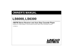
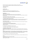
2001-2010
Honda GL1800 Models
Solid Axle Installation Instructions
Oct 2014
125 Industrial Drive | Spearfish, SD 57783 | Toll Free 888.3WHEELS
w w w . l e h m a n t r i k e s . c o m
SAFETY INFORMATION
WARNING
This kit is designed to be installed by a competent technician. Improper installation can affect
the safe operation of your trike, which could also result in serious injury or death. Make sure you
have a complete understanding of the work to be preformed. Unqualified installers are urged to
have the unit installed by a trained technician.
•
Always protect yourself when the vehicle is in the air. Make sure the vehicle is properly supported
anytime you use a hoist or jack.
•
•
•
Always use the proper tools.
Protect your eyes by using proper safety glasses or goggles.
Read through the installation instructions before you begin. Make sure you have all the proper tools,
parts and skill set to perform the installation safely and completely.
© 2008. All rights reserved.
Lehman Trikes provides this publication as is without warranty of any kind, either expressed or implied. While every precaution has been
taken in the preparation of this manual, Lehman Trikes assumes no responsibility for errors or omissions. Neither is any liability assumed for
damages resulting from the use of the information contained herein. Lehman Trikes reserves the right to revise and improve its products as it
sees fit. This publication describes the state of this product at the time of its publication, and may not reflect the product in the future. Lehman Trikes is a registered trademark. All other brands and product names are trademarks or registered trademarks of their respective holders. Printed in the United States of America.
2
SAFETY INFORMATION
UNDERSTANDING SAFETY LABELS & INSTRUCTIONS
READ AND BECOME FAMILIAR WITH ALL WARNING, CAUTION SYMBOLS AND STATEMENTS
LISTED BELOW AND IN THE TEXT OF THIS MANUAL BEFORE YOU BEGIN WORK.
DANGER, WARNINGS & CAUTION SYMBOLS
This is the safety alert symbol. When you see this
symbol on your machine or in this manual, be alert
to the potential for personal injury. Your safety is
involved!
WARNING
SAFETY ALERT WARNING indicates a potential hazard
that may result in severe injury or death to the operator, bystander or person (s) inspecting or servicing the vehicle.
CAUTION
Indicates a potential hazard that may result in minor personal injury or damage to the vehicle.
CAUTION
CAUTION indicates special precautions that must be taken
to avoid vehicle damage or property damage.
NOTE:
NOTE provides key information by clarifying instructions.
IMPORTANT:
IMPORTANT provides key reminders during disassembly,
assembly and inspection of components.
3
CONTENTS
DISASSEMBLY .........................................................................................................................5
TRIMMING FENDER .................................................................................................................9
DRIVELINE DISSASEMBLY .................................................................................................. 11
SPRING REPLACEMENT ...................................................................................................... 13
BRAKE SYSTEM MODIFICATION ........................................................................................ 14
SWINGARM INSTALLATION ................................................................................................ 17
AUXILIARY SHOCK............................................................................................................... 20
DIFFERENTIAL INSTALLATION........................................................................................... 21
BRAKE SYSTEM INSTALLATION ........................................................................................ 23
FRAME INSTALLATION ........................................................................................................ 26
AMPLIFIER INSTALLATION ................................................................................................. 29
LATCH ASSEMBLY ............................................................................................................... 30
TAILLIGHT MODIFICATION .................................................................................................. 32
BODY PREPARATION........................................................................................................... 33
DOOR SWITCH WIRING........................................................................................................ 34
DOOR INSTALLATION .......................................................................................................... 35
BODY INSTALLATION .......................................................................................................... 37
LICENSE PLATE BRACKET INSTALLATION...................................................................... 39
EXHAUST INSTALLATION.................................................................................................... 41
FINAL ASSEMBLY................................................................................................................. 43
TIRE PRESSURE MONITORING SYSTEM (TPMS) ............................................................. 44
ABS DISABLE ........................................................................................................................ 46
HARDWARE BREAKDOWN.................................................................................................. 47
4
PREPARING THE MOTORCYCLE
Disassembly
Fig. 1
NOTE: Refer to Honda service manual for detailed instructions on removal of OEM parts.
1. Load motorcycle on lift and secure front wheel.
2. Place motorcycle on center stand.
3. Remove seat with 6mm Allen socket. Save
grab handles and hardware.
4. See Fig. 1. Remove LH and RH side covers.
Remove and save short screws from extensions. Side cover extensions will not be reused.
5. See Fig. 2. Remove and save side cover grommets from front of saddlebags.
6. Disconnect battery by removing negative cable
first.
7. Disassemble tour box. Remove side and center trim molding. Remove lower cover and inner latch cover. Save all hardware as tour box
will be reinstalled on trike.
8. Disconnect saddle bag latch cables from release levers inside tour box.
9. Remove lights from tour box with an 8mm
socket.
10. Remove cable ties holding tour box harness to
frame. Remove connector holding harness to
rear tab on tour box.
11. Disconnect all wiring for tour box located under
seat. Make note of wiring locations as harness
will need to be installed in same location during
reassembly.
12. Remove tour box mounting hardware with 8mm
socket. Save all hardware. Carefully remove
tour box from motorcycle. Store all tour pack
hardware and trim in tour box as it will be reused.
13. Remove helmet holders from tour pack frame
and discard.
14. Raise trike on lift.
15. See Fig. 3. Remove rear fender cover. Save
(2) upper mounting screws only. Remove license plate bracket and save nuts.
Fig. 2
Fig. 3
5
PREPARING THE MOTORCYCLE
Fig. 4
Disassembly
16. Remove saddlebags from motorcycle.
17. See Fig. 4. Remove and save the following
from LH and RH saddlebags.
• Taillights and mounting nuts
• Large rubber plugs
• Upper front saddlebag mounting washers
18. See Fig. 5. Remove and save the following
from the LH saddlebag only.
• Latch assembly and mounting screws
• Door strikers and mounting screws
• Latch cable
19. Remove and save LH/RH passenger foot
boards and mounting hardware.
20. See Fig. 6. Remove and save rear frame
covers. Save front mounting bolts (2) only.
21. See Fig. 6. Remove and save swingarm pin
covers and hardware.
22. Remove and discard rear crash guards and
hardware.
Fig. 5
LH hardware
shown
Fig. 6
Frame
cover
Pin cover
Discard rear bolt
6
PREPARING THE MOTORCYCLE
Fig. 7
Disassembly
23. See Fig 7. Loosen muffler clamps. Remove
and save muffler mounting bolts and remove
mufflers. Remove and save rubber inserts from
heat shields.
24. See Fig. 7. Remove and save metal inserts
and rubber bushings from saddlebag supports.
25. Remove and save (4) nuts from heat shield on
RH muffler. Discard heat shield.
26. See Fig. 8. 2006+ MODELS Remove and
save (4) amplifier box mounting bolts. Remove
amplifier from rear fender.
NOTE: Long bolts (upper) will be reused for
brake line clamp installation and side stand
switch disabling. Short bolts (lower) will be
used for amplifier installation on trike.
27. See Fig. 9. 2006+ MODELS Remove and
save rear inner plastic fender mounting bolts.
28. Remove rear wheel with 19mm socket. Discard wheel nuts.
29. Remove battery and battery box to access reverse module. Remove and save reverse
module. Remove mounting bracket from reverse module. Temporarily leave battery out
and box loose for easier access to upper shock
mounting hardware.
Save rubber
inserts
Save mounting
hardware
Fig. 8
Fig. 9
7
PREPARING THE MOTORCYCLE
Fig. 10
Disassembly
30. See Fig. 10. Remove side stand switch assembly. Disconnect sensor from side stand
while stand is in the “up” position.
31. See Fig. 11. Secure sensor from turning using
the following hardware.
Remove side stand
• (1) Original Upper Amp Mounting Bolt
• (1) Original Upper Saddlebag Washer
• (1) M6 Flange Lock Nut- CN1902
Fig. 11
Secure sensor
Fig. 1
Tour Box Frame Modification
ALL MODELS
1. See Fig 1. Mark and cut tour box frame as
shown with reciprocating saw or equivalent.
2. Remove tour box frame from motorcycle frame.
And discard mounting hardware. Use touchup
paint on bottom of tour box frame where cuts
were made.
8
PREPARING THE MOTORCYCLE
Fig. 1
Fender Modification
TRIMMING FENDER (2001-05 MODELS)
CAUTION: Do not cut electrical components.
1. See Fig. 1. Mark and trim fender as shown.
2. See Fig. 2. Fender should look as shown when
completed.
Cut here
Cut here
Fig. 2
Modified fender
9
PREPARING THE MOTORCYCLE
Fig. 3
Fender Modification
TRIMMING FENDER (2006+ MODELS)
CAUTION: Do not cut electrical components.
3. See Fig. 3. Mark and Cut amplifier box 1” in
front of rubber cover.
4. See Fig. 4. Mark and cut front half of fender
5 1/2” from rear.
Mark and trim 1”
from rubber cover
Fig. 4
Trim here
5-1/2”
10
PREPARING THE MOTORCYCLE
Fig. 1
Driveline and Suspension Disassembly
Special tools
• Snap On A26 drag link socket
•
•
Remove
from clips
Honda pivot lock nut wrench 07ZMAMCAA100
19mm Allen socket
Swingarm Parts
• Swingarm
LS6300
•
Right swingarm pin
LP6000
•
Left swingarm pin
LP6001
Fig. 2
NOTE: Temporarily leave brake lines attached
to caliper.
Save front
bracket
1. See Fig. 1. Remove rear caliper mounting
bolts with 14mm socket. Free brake lines from
final drive assembly clips.
2. See Fig. 2. Remove front and rear brackets
holding brake lines to swingarm. Save front
mounting bracket.
3. See Fig. 3. Remove final drive assembly from
swingarm using 17mm wrench.
4. Remove driveshaft from swingarm tunnel. Remove and discard rubber driveshaft boot.
Rear
bracket
Fig. 3
Final drive
11
Swingarm
PREPARING THE MOTORCYCLE
Fig. 4
Driveline and Suspension Disassembly
CAUTION: Do not disconnect oil line from
shock to pump. Contents of Honda shock are
under pressure and shock is non-serviceable.
5. See Fig. 4. Temporarily remove shock compressor mounting bolts. Disconnect compressor from wiring harness to allow more slack in
line.
6. See Fig. 5. Remove upper shock nut through
RH side of frame using a 17mm socket and 6”
extension. Hold bolt head through LH side of
frame with 8mm Allen socket and 6” extension.
7. See Fig. 6. Remove rear linkage bolt with
17mm and 19mm sockets. Remove front linkage bolt from motorcycle frame using 19mm
socket and 10mm Allen socket.
8. See Fig. 6. Remove lower shock bolt with
14mm and 17mm sockets.
9. See Fig 6. Raise swingarm and remove swingarm linkage bolt with 19mm socket and 10mm
Allen socket.
10. Remove and save LH swingarm pin lock nut.
Remove LH and RH swingarm pins with 19mm
Allen socket.
11. Remove OEM swingarm. Feed shock through
top of swingarm during removal.
12. Remove rubber boot from transmission and
discard.
Shock compressor
Fig. 5
RH side shown
Access to upper
shock nut
Fig. 6
12
PREPARING THE MOTORCYCLE
Spring Replacement
Fig. 1
Special tools:
• Spring compression tool
Orientation marks
1. See Fig. 1. Loosen set screw on spring and
mark orientation of adjuster to shock body.
2. See Fig. 2. Install spring tool to compress
spring.
3. See Fig. 2. Compress spring and remove retaining ring.
4. Remove old spring and install new heavy duty
spring.
•
Loosen set screw
(1) Heavy Duty Spring– LS0625
5. Compress new spring with compression tool.
6. Align orientation marks while compressing.
7. Re-install retaining ring and slide ring into
groove.
8. Tighten set screw.
Fig. 2
Retaining ring
13
PREPARING THE MOTORCYCLE
Brake System Modification
OEM brake system and trike modifications
The original Honda motorcycle brake system utilizes both front and rear brakes when the foot brake is
applied. During the trike conversion the brake system will be modified.
Once modification is complete, the rear brake pedal will maintain front and rear linked braking. The front
brake lever will operate the front brakes only. The anti-dive valve feature is maintained on both front
and rear braking.
The diagrams below outline the difference between the original Honda GL1800 brake system and the
modified Trikes brake system.
Fig. 1
Fig. 2
Original system
Modified system
14
PREPARING THE MOTORCYCLE
Fig. 1
Brake System Modification- Rear
NOTE: For ABS Disable see pg. 47
1. See Fig. 1. Disconnect inner rear brake line
(upper line on caliper).
2. Disconnect upper line at caliper and discard
brake line.
NOTE: Allow brake line to drain before blocking
off.
3. Block off inner brake line using the following
hardware.
•
(1) M10 Banjo Bolt– CB6001
•
(2) Copper Banjo Washers– GC6002
•
(1) 1/2” Spacer– S001067
Disconnect inner
brake line at fitting
Fig. 2
Block off line
4. See Fig 2. Using cable ties, secure disconnected brake line to top of crossbar on frame.
5. Disconnect lower brake line from caliper.
6. See Fig. 3. Route brake line above plastic
panel on RH side below shock compressor
location.
7. Drill 1/4” hole in plastic and mount brake line
using the following hardware that was saved
from disassembly.
Secure line
above crossbar
• (1) Original Front Brake Line Clamp
• (1) Original Upper Amplifier Mounting Bolt
Fig. 3
• (1) Original Saddlebag Washer
• (1) M6 Lock Nut– CN1902
Mount to
plastic with
original clamp
15
PREPARING THE MOTORCYCLE
Fig. 1
Brake System Modification- Front
1. Remove front fenders and wheel covers.
2. See Fig’s. 1 & 2. Remove OEM line from antidive valve and front master cylinder. Line continues to junction block located on steering
head. Disconnect lower hard line from block.
Remove block from frame and remove entire
line from motorcycle.
3. See Fig. 3. Install new brake line between antidive valve and master cylinder using OEM
banjo bolts and the following hardware. Torque
banjo bolts to 18 ft-lbs.
•
(1) Front brake line- S002066
•
(4) Copper Banjo Washers– GC6002
Anti-dive valve
Master cylinder
Fig. 2
Remove lower
line from block
Fig. 3
New line installed
16
Disconnect
block
SWINGARM INSTALLATION
Swingarm Installation
1. See Fig. 1. Place Lehman swingarm into motorcycle frame. Make sure factory Honda shock is
through center of swingarm during installation. Shock will be mounted into place later.
Fig. 1
ITEM PART #
QTY. DESCRIPTION
0
OEM PARTS
1
LS6300
1
SWINGARM
2
LP6000
1
PIN, SWINGARM, RH
3
LP6001
1
PIN, SWINGARM, LH
17
SWINGARM INSTALLATION
Fig. 2
2. Apply anti-seize compound to threads and
ends of swingarm pins that go into swingarm
bearings.
3. See Fig. 2. Start Lehman swingarm pins into
motorcycle frame.
CAUTION: Do not over-tighten left swingarm
pin. Tighten pin enough to seat in bearing and
adjust to eliminate side-play.
4. Install Lehman swingarm and use a Snap On
A26 drag link socket or similar tool to tighten
pins. Torque right swingarm pin to 80 ft.-lbs.
5. Move swingarm up and down several times to
ensure free movement. Check clearance to
sides and torque left swingarm pin to 25 ft.lbs. This is ensures no lateral play in bearings. Back off left pin and tighten until resistance is felt.
6. Install LH lock nut using Loctite 242. Torque
pivot nut to 80 ft.-lbs. using Honda pivot lock
nut wrench 07ZMA-MCA100. As torque on
this wrench is multiplied, set wrench to 72 ft.lbs.
7. Remove RH front chrome cover and attach
rubber boot to transmission housing. Reinstall
swingarm pn covers with original hardware.
8. See Fig. 3. Install left and right swingarm stop
blocks to motorcycle frame. Apply Loctite 262
to left and right bump stop studs and thread
studs completely into bump stop blocks.
•
(1) RH Stop Block- S001100
•
(1) LH Stop Block- S001102
•
(2) Rubber Bump Stop- S001154
•
(2) M8 x 30 Flange Bolt– CB1921
RH pin
Fig. 3
Install swingarm
stop blocks
L
R
Install bump stops
Fig. 4
9. See Fig. 4. Guide Honda shock into place.
Check position of oil line to shock before installing upper shock bolt. Ensure oil fitting is
on left-hand side and oil line is on right-hand
side. Torque top shock bolt to 31 ft.-lbs.
18
SWINGARM INSTALLATION
Fig. 5
10. See Fig. 5 . Install OEM Honda shock
link to Lehman swingarm with original
hardware and M12 washer under nut
and torque bolt to 47 ft.-lbs.
•
(1) M12 Washer– CW2150
11. See Fig. 6. Install lower shock linkage
with original hardware and torque lower
shock bolt to 31 ft.-lbs. and linkage bolts
to 47 ft.-lbs.
12. Reinstall shock compressor to original
location on frame.
13. Install urethane and steel bushings to
ends of swingarm.
•
(4) Urethane Bushing– LB6301
•
(4) Steel Bushing– LB6303
USE OEM FASTENERS
TO ATTACH SHOCK
SPACER (CW2150) PLACE
WASHER UNDER NUT
Fig. 6
USE STOCK
FASTENERS TO
ATTACH SHOCK
LINKAGE
19
INSTALLATION
Auxiliary Shock
Fig. 7
1. See Fig’s. 7 & 8. Install lower end of auxiliary
shock with shim and flange bushing as shown.
Apply a small amount of lube to bushing.
•
(1) 5/8 Shim– CS4030
•
(1) Flanged Bushing– LB6314
Shock shim
Fig. 8
Bushing– Flange
on RH side
20
DIFFERENTIAL INSTALLATION
Fig. 1
Differential Installation
NOTE: The OEM transmission output shaft boot
is not reused.
1. Shift transmission into NEUTRAL.
2. See Fig. 1. Install U-joint to driveshaft yoke.
Grease fitting should face yoke.
•
(1) Driveshaft Yoke– LY1002
•
(1) U-Joint– S002086
3. See Fig. 2. Apply Loctite retaining compound
(Green) to yoke splines and Install the stub
shaft into yoke. End of shaft should be flush
with yoke surface. Install set screw and torque
to 19 ft-lbs.
•
(1) Stub Shaft– LS6305
•
(1) Set Screw– CS3978
Fig. 2
Secure with
set screw
4. See Fig. 3. Install collar and spring to OEM
driveshaft as shown.
•
(1) Driveshaft Collar– S002091
•
(1) Driveshaft Spring– S002201
5. Grease all internal splines on Honda motorcycle yoke.
NOTE: Ensure that centers of universal
joints are aligned in phase as closely as
possible (centers may not line up exactly).
6. See Fig. 4. Assemble drive shaft as shown.
7. Install drive shaft through swingarm tunnel and
onto output shaft of transmission. Ensure driveshaft is fully engaged on transmission output
shaft.
Shaft flush
with yoke
Fig. 3
Spring
Collar
Fig. 4
Align U-joints
21
DIFFERENTIAL INSTALLATION
Fig. 5
Differential Installation
8. See Fig. 5. Mount differential to swingarm using the following hardware. Apply Red Loctite
to threads. Align rear u-joint to differential yoke
during installation.
NOTE: Do not torque differential mounting
hardware until stabilizer and driveshaft have
been properly adjusted.
•
(4) M12 x 100 Bolts– CB1612
•
(4) 7/16” Flat Washers- CW2022
•
(4) M12 Lock Nuts– CN1916
9. See Fig. 6. Attach driveshaft to differential
yoke using the following hardware. Use Blue
Loctite and Torque nuts to 18 ft-lbs.
•
Mount differential
Fig. 6
(1) U-Bolt kit– S002202
22
DIFFERENTIAL INSTALLATION
Fig. 7
10. See Fig. 7. Assemble new stabilizer bar
with jam nuts and rod ends. Install LH
threaded rod end into end of stabilizer bar
with groove as shown.
11. See Fig. 8. Install stabilizer to bracket on
differential using the following hardware.
Torque to 78 ft-lbs.
•
(1) 1/2” x 2-1/4” Bolt– CB1410
•
(2) 1/2” Flat Washers– CW2025
•
(1) 1/2” Lock Nut– CN3060
Stabilizer assembly
LH thread rod end
12. See Fig. 8. Attach stabilizer to lower shock
mount using the following hardware. Install
with head of bolt against rod end. Use flat
washer on nut side only. Torque to 78 ftlbs.
•
(1) 1/2” x 3” Bolt– CB1425
•
(1) 1/2” Flat Washers– CW2025
•
(1) 1/2” Lock Nut– CN3060
LH threaded end
on stabilizer
Fig. 8
Auxiliary shock
13. See Fig. 5. Center driveshaft in swingarm
tunnel by rotating stabilizer bar left or right
as needed. Tighten front and rear jam nuts
once driveshaft is centered.
14. Tighten differential mounting hardware.
Torque to 85 ft-lbs.
Attach stabilizer
23
BRAKES
Fig. 1
Brake Installation
1. See Fig. 1. Install single brake line (line with
straight tab) to residual valve using the following hardware. Torque banjo bolt to 16 ft-lbs.
•
(1) Residual Valve– S002037
•
(1) M10 Banjo Bolt– CB6001
•
(2) Copper Banjo Washers– GC6002
3. Remove rear brake reservoir cap.
4. Bleed rear brake system at rear calipers with
brake bleeder or hand operated vacuum pump.
5. Bleed front brake system with rear pedal in the
following order. Refer to Honda service manual
for further information.
•
Fig. 2. LH front, upper bleeder
•
Fig. 3. RH front, lower bleeder
•
Fig. 4. LH front, anti-dive valve
6. Repeat bleeding on front and rear until all air is
eliminated from brake system. Verify rear
brake pedal and front brake lever are firm and
do not bottom out.
7. Fill fluid reservoir and install cap.
NOTE: New brake pads and rotors will have a
break-in period before optimum brake operation is achieved.
8. Reinstall front fender and wheel covers.
Fig. 2
Front LH upper bleeder
Fig. 3
Fig. 4
LH Anti-dive bleeder
24
BRAKES
Fig. 1
Park Brake Cables
Secure to bracket
1. See Fig. 1. Install park brake cable to caliper
brackets. Secure cable to bracket with cir-clip
on cables.
2. See Fig. 2. Route LH cable around axle tube
as shown towards RH side of trike. Secure to
axle tube with cable ties as needed.
3. See Fig. 3. Route RH cable around axle tube
as shown. Secure to LH cable with cable ties
as needed.
Attach cable
Fig. 2
LH side
Fig. 3
RH side
25
BRAKES
Fig. 1
Park Brake Installation
1. See Fig. 1. Remove one snap ring from either
side of park brake handle pin and remove pin.
2. Align pivot hole with holes in bracket. Make
sure ratchet catch is in place over tab on park
brake bracket.
3. Install pivot pin through assembly and reinstall
snap ring.
4. Assemble park brake lever to park brake
bracket.
•
(1) Park Brake Lever- GB1099M
•
(1) Park Brake Bracket- LB6322
1
5
3,4
Item#
1
2
3
4
5
Part#
GB1099M
LB1294
CC3106
CC4017
LB6322
5. Attach cable pulling bracket to park brake
lever assembly using clevis and cotter pin.
•
(1) Cable Pulling Bracket– LB1294
•
(1) Clevis Pin– CC3106
•
(1) Cotter Pin– CC4017
Description
2
Park Brake Lever
Cable Pulling Bracket
Clevis Pin
Cotter Pin
Park Brake Bracket
Fig. 2
Attach bracket
to swingarm
6. See Fig. 2. Attach park brake bracket (LB6322)
to swingarm using the following hardware.
Torque bolts to 36 ft.-lbs.
•
(2) M10 x 25 Flange Bolts– CB1928
•
(2) M10 Flange Nuts– CN1910
Secure cables to brackets
7. See Fig. 2. Route cables through holes in park
brake bracket. Secure to bracket with nuts and
washers supplied with cables.
8. See Fig. 2. Install cables through cable pulling
bracket with jam nut on each side of bracket.
•
(4) 5/16 NF Nuts– CN3009
9. Adjust park brake at lever assembly. Park
brake should fully engage at 3-4 clicks on
lever.
26
FRAME INSTALLATION
Fig. 1
Frame Installation
1. See Fig. 1. Position Lehman frame above differential.
2. See Fig. 2. Install left and right upper mounting bolts to secure frame using M8 Flange
Bolts.
•
Lehman frame
(2) M8 x 1.25 x 25 Flange Bolts– CB1920
3. See Fig. 3. Install aux. shock into upper shock
mount. While aligning holes, insert upper aux.
shock bushing into shock mount and aux.
shock.
•
(1) Upper Shock Bushing– LB6313
4. Apply red Loctite (262) to upper shock bolt with
flange nut. Torque bolt to 36 ft.-lbs.
•
(1) M10 x 1.5 x 45– Flange Bolt– CB1935
•
(1) M10 Flange Nut– CN1910
Fig. 2
Upper mounting bolts
Fig. 3
Upper shock bushing
27
FRAME INSTALLATION
Fig. 4
5. See Fig. 4. Install left and right lower mounting bolts to secure frame using (2) M8x1.25x30
GR 8.8 hex flange bolts.
•
(2) M8 x 1.25 x 25 Flange Bolts– CB1920
6. Drill out lower frame holes on tour pack frame
to 11/32”.
7. See Fig. 5. Install upper tour pack frame bolts
and tour pack frame: top holes use M8 x 50mm
flange bolts and original M8 flanged nuts; bottom holes-use original top tour pack M8 x 40
bolts. Torque bolts to 18 ft.-lbs.
•
(2) M8 x 50 Flange Bolt– CB1923
•
(2) M8 Flange Nuts– OEM
•
(2) M8 x 40 Flange Bolts– OEM
Lower mounting bolts
Fig. 5
8. See Fig. 4. Torque front frame mounting hardware to 22 ft. lbs. Once front trike frame hardware is secure, remove upper tour pack frame
hardware and remove tour pack frame from
trike until after the body is installed.
9. See Fig. 6. Attach reverse resistor to frame on
left side side using the original mounting hardware.
10. Connect electrical connectors and battery feed.
Upper tour pack frame bolts
Fig. 6
Reverse resistor
28
FRAME INSTALLATION
Fig. 7
11. See Fig. 7. Original frame covers require modification before reinstalling.
12. See Fig. 8. Trim rear cover as needed for
proper clearance around trike frame. Reinstall
frame covers with original hardware in front
and cable tie in rear.
Before Modification
Fig. 8
After Modification
29
AMP INSTALLATION
Fig. 1
Amplifier Installation– 2006+ Models
1. Remove metal inserts from amplifier mounting
holes.
2. See Fig. 1. Install amplifier mounting brackets
to motorcycle frame using the following hardware.
•
(2) Amplifier Mounting Brackets– LB6325
•
(2) Bolts From OEM Inner Fender
•
(2) Nuts From OEM License Plate Bracket
LH bracket
shown
NOTE: LH bracket is mounted on inside of
frame tab. RH bracket is mounted on outside
of frame tab.
3. See Fig. 1. Mount amplifier box using the following hardware.
•
(2) Bolts From OEM Rear Fender Cover
•
(2) 5/16” Flat Washers– CW2010
•
(2) Nuts From OEM Heat Shield
Fig. 2
4. See Fig. 2. Drill 1/4” holes where plastic fender
and amplifier box overlap. Install with the following hardware.
•
(2) Bolts From OEM Amplifier Box Mounting
•
(2) Nuts From OEM Heat Shield
5. See Fig. 3. Amplifier box should look as shown
when complete.
30
RH attachment
Fig. 3
LATCH MODIFICATION
Fig. 1
Latch Modification
Bend cable tab straight
1. See Fig. 1. Remove release cable and plastic
clip from LH latch assembly.
2. See Fig. 1. Bend cable tab straight.
3. See Fig. 1. Remove original release lever.
4. See Fig. 2. Install cable extension using the
following hardware.
NOTE: Tighten screw just enough to engage
lock nut. Over tightening will cause extension
bracket to bind up.
•
(1) Cable Extension– LB6319
•
(1) 10/32” x 1/2” Machine Screw– CS4066
•
(1) 10/32” Lock Nut– CN3068
Remove release lever
5. See Fig. 2. Install latch assembly and cable
bracket to latch bracket using the following
hardware.
•
(1) Latch Mount Bracket– LB6302
•
(1) Cable Bracket– LB6320
•
(4) OEM Phillips Screws (From Saddlebag)
Fig. 2
Cable bracket
Safety
cable
6. See Fig. 2. Install cable clip and cable to new
extension.
7. Test latches to verify they release at the
same time. Adjust rod length as needed.
Door may not release properly if latches do
not release together.
8. See Fig. 2. Install cable clamp to safety release cable. Loop cable through small hole in
cable extension bracket and crimp cable
clamp.
•
(1) Cable Clamp- CC1900
•
(48”) Safety Cable
Remove clip and cable
Extension
Latch bracket
Fig. 3
9. See Fig. 3. Complete latch assembly should
look as shown.
31
LATCH INSTALLATION
Fig. 1
Latch Installation
1. See Fig. 1. Install latch assembly into trunk
using the following hardware. Leave latch
loose to move in slots.
•
(4) M6 x 16 Button Head Bolts- CB1904
•
(4) M6 Fender Washers- CW2107
2. See Fig. 2. Route latch cable through large
hole in front trunk wall. Secure grommet in
hole.
3. See Fig. 2. Route safety release cable through
small hole in front trunk wall.
4. Apply silicone around safety release cable
from inside trunk.
Fig. 2
Safety cable
Latch cable
32
TAILLIGHT MODIFICATION
Taillight Modification– 2006+ Models
Fig. 1
1. One taillight mounting stud and part of plastic
landing needs to be removed. This stud is the
short stud closest to pointed corner of red lens
closest to centerline of motorcycle when
mounted.
2. See Fig. 1. Cut plastic and stud approximately
3/16” above tiny slot in bottom of landing. .
This will leave a flat base about 3/16’’ thick. .
3. Drill a 3/16” hole in center of new flat landing
for a screw to retain metal adapter.
4. See Fig. 2. Insert short side of taillight adapter
to each light using the following hardware.
•
(2) Taillight Adapter– LP6301
•
(2) 1/4” SS Flat Washers– CW2006
•
(2) 10-24” x 1/2” Phillips Screws– CB1009
Cut plastic stud
3/16” above opening
3/16”
Fig. 2
LH Side
Rear Harness Modification
5. See Fig. 3. Remove rubber grommet from
center of LH/RH saddle bag wiring harness.
NOTE: Do not remove rear grommet from
taillight pocket wiring.
6. Remove excess electrical tape and reposition
latch sensor connector toward front of harness.
Cover exposed wires with electrical tape.
Short side of adapter
Fig. 3
33
BODY
Fig. 1
Body Preparation
1. See Fig. 1. Install side cover brackets to body
using the following hardware.
• (1) LH Side Cover Bracket- LF6305-BL
• (1) RH Side Cover Bracket- LF6305-BR
• (4) M6 x 25 Button Head Bolts– CB1911
• (4) M6 Fender Washers– CW2107
• (4) M6 Lock Nuts– CN1902
2. See Fig. 1. Install grommets (from OEM saddlebags) into side cover brackets.
3. Install trike wiring harness to plastic clips on
body.
4. Install side cover extensions to OEM side covers using original hardware. Install trim seal
along back edge of extension.
Fig. 2
• (2’) Trim Seal- CW2505
5. Install modified wiring harnesses to body. Use
harness with main red connectors on LH side
and blue connectors on RH side.
NOTE: Turn signal connectors are different between 2001-06 and 2007-10 models.
6. See Fig. 2. Install harness grommets through
taillight pockets on each side.
7. See Fig. 3. Connect taillights to harness and
carefully install into body using the following
hardware.
Grommet
Grommet
• (6) 1/4” Stainless Flat Washers- CW2008
• (6) OEM Taillight Mounting Nuts
8. See Fig. 2. Install large OEM rubber grommets
over turn signal connectors (large holes in
body).
9. See Fig. 3. Plug extra taillight mounting holes
(locations vary by model year) with silicone.
Fig. 3
Grommet
Silicone extra holes
34
BODY
Fig. 4
Door Switch Wiring
10. See Fig. 4. Place rubber grommet in access
hole as shown and route door switch through
hole.
Grommet
Door latch
wiring
• (1) Rubber Grommet– GG0011
11. Install trunk switch harness through grommet.
Apply silicone around harness from inside
trunk.
• (1) Latch Wiring Harness– GH0026
12. Install plastic connector onto terminals inside
trunk.
13. Plug harness into latch assembly.
14. Apply silicone around harness and grommet
from inside trunk.
35
DOOR INSTALLATION
Fig. 1
Door Installation
NOTE: Remove any residue from seal mounting
surface on door before installing seal.
1. See Fig. 1. Install trunk door seal starting at
the bottom center of trunk opening. Solid lip on
seal will face trunk edge.
2. See Fig. 2. Install original strikers and hardware from LH saddlebag to top of trunk door.
3. Verify hinges are in the middle of adjustment
slots in trunk.
4. See Fig. 3. Before installing door, check spacing of door hinges for consistency from side to
side. If hinges are not equal, loosen hardware
on crossbar between hinges. Twist bar until
hinges are equal and tighten hardware.
Start seal here
Fig. 2
RH striker shown
Fig. 3
Crossbar
Consistent spacing
36
DOOR INSTALLATION
Fig. 4
5. See Fig. 4. Install trunk door to body using the
following hardware. Leave hardware loose.
• (6) M6 x 16 Button Head Bolts- CB1904
• (6) M6 Fender Washers- CW2107
CAUTION: Slowly close door and ensure strikers clear top of trunk opening. Bend strikers
down if necessary. Strikers should just clear
opening.
6. Slowly close door (do not try to latch door at
this time). Adjust door from side to side and
up and down to match body. Once door is in
place, slowly open and tighten mounting hardware.
7. See Fig. 5. Lower door and check for consistent spacing between door and body.
8. Pull latch assembly towards rear of body and
tighten hardware. Align strikers from side to
side to match opening on each latch.
9. Latch door. Verify that both side latch when
closed. Adjust latch assembly in or out as
needed.
10. See Fig. 6. Door adjustment is made using the
following:
Door mounting
Fig. 5
Consistent spacing
• Moving hinges upward in trunk results in the
top of door tilting outward and away from
body.
• Moving hinges downward will bring door
closer to body.
• Latch can be slide in or out to adjust gap on
top and take out any excessive play in door.
Fig. 6
Loosen bolt
and adjust
as needed
37
BODY INSTALLATION
Fig. 1
Body Installation
Note: The installation/alignment of the body is
an important process to find the correct position of the body in relation to the wheels.
1. Carefully place body on trike frame.
2. Install original tour pack frame to trike frame.
Torque hardware to 18 ft. lbs.
3. Position body on frame. Use rubber spacers as
needed on front and rear mounting holes.
4. See Fig. 1. Install side covers and adjust body to
achieve a consistent 1/8” gap between the front
of body and side cover.
5.
See Fig’s 2 & 3. Align body to trike. Center
body by checking side to side (wheel opening)
and front to back (front of fender) measurements.
6. Determine body height by measuring from inner fender down to center of axle.
7. Ensure gaps at side covers are tight and equal
on both sides.
Fig. 2
NOTE: Adjust body height by adding or removing shims as needed.
Fig. 3
38
BODY INSTALLATION
Fig. 4
8. See Fig. 4. From below trike, drill 1/4" holes in
center of body mount tabs on Lehman frame.
9. Install the body to the frame using the following
hardware. Tighten hardware down evenly.
• (4) M6 x 35 Socket Head Bolts– CB1934
• (4) 1/4” x 1.25 Fender Washers- CW2108
• (4) M6 Fender Washer- CW2107
• (4) M6 Flange Nut- CN1902
10. See Fig. 5. Install fender braces to middle predrilled hole in front of body. Attach to body using
the following hardware. Apply Loctite 242 and
tighten hardware.
Drill 1/4” holes in body
• (1) LH Fender Brace– LB6323
• (1) RH Fender Brace– LB6324
Fig. 5
• (2) M8 x 20 Flange Bolt– CB1919
• (2) M8 Flange Nut– CN1905
11. See Fig. 5. Clamp other end of brace to Lehman frame and drill second mount hole in trike
frame using an 11/32” drill bit. Attach to trike
frame using the following hardware. Use (1) M8
x 1.25 x 20mm flange bolt and (1) M8x1.25
flange nut to attach brace to frame. Apply Loctite
242 and tighten hardware.
• (2) M8 x 20 Flange Bolt– CB1919
• (2) M8 Flange Nut– CN1905
39
Fender braces
LICENSE PLATE BRACKET INSTALLATION
Fig. 1
License Plate Installation
1. Use stock license plate bracket and a license
plate to mark location of license plate bracket
in middle of body on raised surface.
2. Cover area to be drilled with masking tape,
center and level bracket and mark holes.
NOTE: Make sure license plate has proper
clearance between door and hitch (if applicable)
3. See Fig 1. Drill (2) 1/4” holes 1-1/2” from bottom of trunk opening and mount bracket into
place.
4. See Fig 1. Drill (1) 7/16" hole for license light
wires centered between license plate bracket
bolts and 3” from bottom of trunk opening. Drill
hole so it is toward top of bracket so it is unseen when plate is on. Install grommet in body.
• (1) Rubber Grommet– GG0011
5. Attach license plate bracket to body using the
following hardware.
• (2) M6 x 25 Button Head Bolts– CB1911
• (2) 1/4” Flat Washers– CW2006
• (2) M6 Flange Lock Nuts– CN1902
6. See Fig. 2. Bolt license plate light using the
following hardware.
• (1) License Plate Light– S001469
• (1) Support Plate– S001601
• (2) M6 x 16 Button Head Bolts- CB1904
• (2) M6 Washers– CW2154
• (2) M6 Lock Nut– CN1903
40
Fig. 2
LICENSE PLATE BRACKET INSTALLATION
Fig. 3
7. See Fig. 3. Measure 5" of wiring from back
side of light and cut excess wire.
8. See Fig. 3. Install (2) female terminal pins and
(1) male connector to wiring from light.
9. See Fig 3. Install black clip (BT3001) to secure
wiring to plate. Cut plug from original license
plate light and add 34" of wire. Cover with heat
shrink.
NOTE: Connect license plate wiring as follows.
(-) Black wire on light to green on harness
(+) Red wire on light to brown wire on harness
10. Run wire through body grommet from back
side and install (2) male terminal pins and (1)
female connector.
11. See Fig. 4. Connect wiring and install light assembly to bracket using the following hardware.
• (2) M6 x 16 Button Head Bolts- CB1904
• (2) M6 Flange Lock Nuts– CN1902
41
Fig. 4
EXHAUST
Exhaust Installation
1. See Fig.’s 1 & 2. Assemble exhaust components as shown.
Fig. 1
Fig. 2
CN1902
Honda Parts
42
EXHAUST
Fig. 3
2. See Fig. 3. Attach mufflers to mounting brackets using the original hardware.
3. Adjust fit relative to body, side to side. About 1”
of muffler should extend past rear of body.
4. See Fig. 4. Center exhaust tips in body cutouts. Adjust to equal height.
5. Tighten exhaust clamps and all mounting hardware.
Attach Muffler
Fig. 4
Exhaust tips centered in cut-outs
43
FINAL ASSEMBLY
Fig. 1
Final Assembly
1. Set tour box in place on frame. Make sure all
wiring is routed in the proper location before
attaching tour box to frame.
2. Attach tour box to frame with original hardware.
NOTE: Leave mounting hardware loose until
lower trim panels are installed.
3. Attach trunk release cable to tour box latch
assembly on RH side.
4. See Fig. 1. Cut 1-1/2” x 1/4” slot into lower
cover as shown for cable clearance.
5. Reinstall all tour box trim and lights into OEM
locations using original hardware.
6. Reconnect tour box connectors to motorcycle
harness.
7. Plug in all electrical connectors from trike harness to motorcycle harness.
8. Connect battery and check lights for proper
operation.
9. Tighten all tour box mounting hardware.
10. See Fig. 2. Route safety cable to front of tour
box. Install cable clamp and make small loop.
Crimp cable clamp and secure to front of tour
box
•
Fig. 2
Fig. 3
(1) Cable Clamp- CC1900
11. Install seat and grab handles using original
hardware.
12. Install passenger footboards using original
hardware.
13. Verify all side covers are reinstalled.
14. Install wheels and torque lug nuts to 85 ft-lbs.
Install center caps (if applicable).
15. See Fig. 3. Install badges on trunk door. Place
Lehman badge on LH side and Monarch II
badge on RH side.
•
(1) Lehman Badge– GB1320
•
(1) Monarch II Badge– GB1321
16. Remove motorcycle center stand.
NOTE: RH center stand bolt has LH threads.
44
TPMS DISABLE
Fig. 1
Tire Pressure Monitoring System (TPMS) Disable (If applicable– 09+ models)
NOTE: Refer to Honda service manual for detailed information.
1. See Fig. 1. Carefully remove RH trim
2. See Fig. 2. Remove the RH fairing storage
compartment.
3. See Fig. 3. Disconnect wire harness.
4. Remove mounting bolts and remove module
from bike
Remove faring trim
Fig. 2
Remove screws
Remove clips
Fig. 3
Disconnect harness from control module
45
TPMS DISABLE
5. See Fig. 4. Splice white wire with yellow stripe and black wire with white stripe to solid green wire.
NOTE: Splice wiring from connector side.
6. Cover all exposed wires with heat shrink.
7. Reconnect module. Turn on ignition and verify TPMS light is not illuminated.
8. Reinstall module, storage compartment and fairing trim.
9. Place TPMS disabled sticker inside tour box lid.
Fig. 4
Splice White/Yellow
wire and Black/White
wire to solid Green wire
46
ABS DISABLE
ABS Disable (If applicable)
Fig. 1
1. Disconnect battery and verify ignition is in the
“OFF” position.
NOTE: ABS control module location will vary
depending on model year. Refer to the Honda
service manual for access to module.
1. Remove all ABS related fuses from fuse panel.
Location will vary by year.
2. See Fig 1. Unplug ABS control module. Position black 5-pin connector so the unplugged
end is facing you with 3-pin slots on the bottom
3. See Fig 1. Remove a small amount of plastic
between bottom center and bottom right pin
slots. Remove only enough material to install a
mini fuse.
4. Install 5 amp mini fuse from fuse panel into
bottom center and bottom right slots. Verify
that fuse connects yellow/blue wire (ABS light)
to larger green wire (ground).
5. Use electrical tape to cover plug and secure
fuse into place.
6. Reconnect battery and verify ABS light remains off.
47
FINAL INSPECTION
PROCEDURE
GOOD
RE-WORK
1.
Reflectors installed (if applicable)
□
□
2.
Lights and horn work
□
□
3.
Park brake operation
□
□
4.
Engine/Transmission oil levels
□
□
5.
Wheel torque 85ft. lbs (75ft. lbs-wire)
□
□
6.
Rear tire pressure 26 psi
□
□
7.
Front tire pressure 36 psi
□
□
8.
Trunk latch on right handle of tour pack
□
□
9.
Trunk clean and dry
□
□
10.
Trunk door seals and operates smoothly
□
□
11.
Honda shock set @ 13
□
□
12.
Auxiliary shock set @ mid setting
□
□
13.
Heat shields/Side covers
□
□
14.
Monarch II/Lehman badge installed
□
□
15.
Accessories (if applicable)
□
□
16.
No paint defects
□
□
17.
Warranty/Owners manual with trike
□
□
48
HARDWARE
GB6300 BOLT BAG-DRIVETRAIN
(Hardware quantities vary by model year)
QTY. PART #
DESCRIPTION
1
CB1410
SCR, HX, .50-13 X 2.25, GR. 5, ZN
1
CB1425
SCR, HX, .50-13 X 3.00, ZN
4
CB1612
SCR, HX, M12-1.75 X 100, ZN
4
CB1905
SCR, FH, M6-1.00 X 20, CL 8.8 ZN
5
CB1920
SCR, FH, M8-1.25 X 25, CL 8.8, ZN
2
CB1921
SCR, FH, M8-1.25 X 30, CL 8.8, ZN
2
CB1923
SCR, FH, M8-1.25 X 50, CL 8.8, ZN
2
CB1928
SCR, FH, M10-1.5 X 25 CL 8.8 ZN
1
CB1935
SCR, FH, M10-1.5 X 45, CL 8.8 ZN
2
CB6001
BANJO BOLT, M10 X 1
1
CC3106
PIN, CLEVIS (5/16 X 19/32) 50/BX
1
CC4017
PIN, COTTER, 3/32 X 1/2
4
CN1902
NUT, NL, FG, M6-1 ZN
3
CN1910
NUT, FG, M10-1.5 CL 8.8, ZN
4
CN1916
NUT, NL, M12-1.75 CL, 10.9, ZN
4
CN3009
NUT, .31-24, GR. 8, ZN
1
CN3040
NUT, NL, .25-20 ZN
2
CN3060
NUT, NL .50-13 ZN
1
CS4030
SPACER, MACH. BUSHING, 5/8 X 1 1/8
4
CW2025
WSH, FL, .50, GR. 8
4
CW2022
WSH, FL, .44 GR. 8 ZN
1
CW2150
WSH, FL, M12 X 24 2.5 MM
2
CW2160
WSH, FL, 6.4 X 11 X 1.6 MM
8
GC6002
WSH, COPPER BANJO M10
1
S001067
1/2” OD X .375” SPACER
1
S002066
BRAKE LINE, BRAIDED– 11.50”
49
HARDWARE
GB6301 BOLT BAG-DRIVETRAIN
(Hardware quantities vary by model year)
QTY. PART #
DESCRIPTION
1
BT3001
WIRE TAB, BLACK
14
CB1904
SCR, FB, SK, M6-1.00 X 16, CL 10.9, ZN
10
CB1911
SCR, FB, SK, M6-1.00 X 25, CL 10.9, ZN
4
CB1919
SCR, FH, M8-1.25 X 20, CL 8.8, ZN
4
CB1934
SCR, FB, M6-1.00 X 35, CL 8.8, ZN
2
CC1900
CABLE CLAMP
14
CN1902
NUT, NL, FG, M6-1, ZN
2
CN1903
NUT, NL, M6 SS
4
CN1905
NUT, FG, M8-1.25 CL 8.8, ZN
1
CN1908
NUT, NL M8-1.25 CL 8.8 ZN
1
CN3068
NUT, NL, 10-32
2
CS4023-1
SCR, PN, PH, 10-24 X 1.00
1
CS4066
SCR, RD, PH, 10-32 X 0.50
2
CT1020
CABLE TIE 11.1”
8
CW2006
WSH, FL, .25 SS
2
CW2010
WSH. FL, .31 X 1.50 X .25 RUBBER
8
CW2097
WSH, .31 X 1.50 X .25 RB
18
CW2107
WSH, FENDER, 6.4MM X 24MM PLATED
4
CW2108
WSH .28 X 1.25 X .06
2
CW2154
WSH, FL, 6.4 X 18 X 1.8 ZN
2
CW2167
WSH, FL, M8 ZN
2
CW2505
SEAL, 3/8 X 7/32”
2
GG0011
GROMMET, 1/4 ID X 7/16 OD X 1/4, GROOVE
50