1
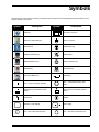
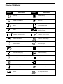
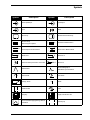
®
Ultraview 1050 Monitor
90369
Technical Reference
070-0707-00 Rev. D
more time to care
Table of Contents
Chapter
Page
Drawings
Schematics . . . . . . . . . . . . . . . . . . . . . . . . . . . . . . . . . . . . . . . . . . . . . . . . . . . . . . . . . . . . . . 1-1
Symbols
i
© 2004 Spacelabs Medical, Inc.
All rights reserved. Contents of this publication may not be reproduced in any form without the written permission of Spacelabs
Medical. Products of Spacelabs Medical are covered by U.S. and foreign patents and/or pending patents. Printed in U.S.A.
Specifications and price change privileges are reserved.
Spacelabs Medical considers itself responsible for the effects on safety, reliability and performance of the equipment only if:
•
•
•
assembly operations, re-adjustments, modifications or repairs are carried out by persons authorized by Spacelabs
Medical, and
the electrical installation of the relevant room complies with the requirements of the standard in force, and
the equipment is used in accordance with the operations manual.
Spacelabs Medical will make available, on request, such circuit diagrams, component part lists, descriptions, calibration instructions
or other information which will assist appropriately qualified technical personnel to repair those parts of the equipment which are
classified by Spacelabs Medical as field repairable.
Spacelabs Medical is committed to providing comprehensive customer support beginning with your initial inquiry through purchase,
training, and service for the life of your Spacelabs Medical equipment.
CORPORATE OFFICES
U.S.A.
Spacelabs Medical
5150 220th Ave SE
Issaquah, WA 98029
Telephone: 425-657-7200
Telephone: 800-522-7025
Fax: 425-657-7212
Authorized EC Representative
UNITED KINGDOM
Spacelabs Limited
71 Great North Road, Hatfield
Herts AL9 5EN
Telephone: 44-1707-263-570
Fax: 44-1707-260-065
BirthNet, Data Shuttle, Flexport, Intesys Clinical Suite, Maternal Obstetrical Monitor, MOM, Mermaid, Multiview, PCIS, PCMS,
PrintMaster, Quicknet, Sensorwatch, TRU-CAP, TRU-CUFF, TRU-LINK, UCW, Ultralite, Ultraview, Ultraview Clinical Messenger,
Ultraview SL, Uni-Pouch, Universal Flexport, Varitrend and WinDNA are trademarks of Spacelabs Medical, Inc.
Other brands and product names are trademarks of their respective owners.
CAUTION:
Rx
Only
US Federal law restricts the devices documented herein to sale by, or on the order
of, a physician.
Drawings
Contents
Schematics . . . . . . . . . . . . . . . . . . . . . . . . . . . . . . . . . . . . . . . . . . . . . . . . . . . . . . . . . . . . . . . . . . . . 1
Schematics
Title
Drawing
90369 P/N 676-0151-03
1-1
(39 sheets)
90369 P/N 676-0151-01
2-1
(7 sheets)
CAUTION:
•
Printed circuit boards in this equipment contain static sensitive devices;
only handle at a static-safe workstation.
1-1
Symbols
The following list of international and safety symbols describes all symbols used on Spacelabs Medical products. No one
product contains every symbol.
Symbol
Description
Symbol
Description
HELP Key
Keyboard Connection
SPECIAL FUNCTIONS Key
Mouse connection
RECORD Key
START/STOP Key
NORMAL SCREEN Key
START/STOP
MONITOR SETUP Key
STOP or CANCEL Key
ALARMS Key
CONTINUE Key
PREVIOUS MENU Key
ENTER Key
ON — Power Connection to Mains
OFF — Power Disconnection from
Mains
ON Position for Push Button Power
Switch
OFF Position for Push Button Power
Switch
On Direction
ON/OFF
Television; Video Display
Video Output
ON — Part of the Instrument Only
OFF — Part of the Instrument Only
2-1
Ultraview 1050 Monitor
Symbol
Description
2-2
Description
Stand-by
STAND-BY Key
PAUSE or INTERRUPT
Slow Run
Reset
Power Indicator LED
Alarm
Temporary Shut Off of Alarm Tone or
Screen Indicators
Indicator — Remote Control
Indicator — Local Control
PRINT REPORT Key
Indicator — Out of Paper
Partial ON/OFF
Recorder Paper
Normal Screen
?
Symbol
1
2
3
1
2
3
Return to Prior Menu
Clock/Time Setting Key
TREND/TIMER Key
HELP (Explain Prior Screen) Key
Keypad
Activate Recorder for Graphics
Indoor Use Only
START (NIBP) Key
Auto Mode (NIBP)
Output
No Output (Terminated)
Symbols
Symbol
Description
1
2
3
Input/Output
Input
Reset
Menu Keys
Waveform/Parameter Keys
B
Access Special Function Menu
1
Serial Port 1
1
2
3
A
1
2
3
Set Initial Conditions Menu
Return Unit to Monitor Mode
2
External marker push button connection
SDLC
Serial Port 2
SDLC Port
Arterial Pulse
Electrocardiograph or
Defibrillator Synchronization
Gas Exhaust
Foot Switch
Enlarge, Zoom
12,200 m
Description
Data Input/Output
Monitor Setup
Select Program Options
1
2
3
Symbol
x
Delete
PCMCIA Card
Event
Keep Dry
Fragile; handle with care
Environmental Shipping/Storage Altitude
Limitations
This Way Up
2-3
Ultraview 1050 Monitor
Symbol
2-4
Description
Symbol
Description
Environmental Shipping/Storage
Temperature Limitations
Environmental Shipping/Storage
Humidity Limitations
Open Padlock
Closed Padlock
Down Arrow
Up Arrow
Hard Drive
Power Indicator LED
Antenna
Mermaid Connector
Microphone
Omnidirectional Microphone
Audio Output, Speaker
Activate Telemetry Recorder
Network Connection
Universal Serial Bus
Gas Sampling Port
Gas Return Port
Remote Alarm; Nurse Alert
Nurse Call
Battery Status
Low Battery
Battery
Replace only with the appropriate
battery.
Replace only with the appropriate
battery.
(+ / - signs may be reversed)
Symbols
Symbol
Description
Symbol
All batteries should be disposed of
properly to protect the environment.
Lithium batteries should be fully
discharged before disposal. Batteries
such as lead-acid (Pb) and nickelcadmium (Ni-Cd) must be recycled.
Please follow your internal procedures
and or local (provincial) laws regarding
disposal or recycling.
Description
Caution - hazardous voltages. To reduce
risk of electric shock, do not remove the
cover or back. Refer servicing to a
qualified service personnel (U.S.A.).
DANGER - High Voltage (International)
Protective Earth Ground
Functional Earth Ground
Replace Fuse Only as Marked
Fuse
Power supply jack polarity.
(+ / - signs may be reversed)
Equipotentiality Terminal
Alternating Current
Direct Current
Both Direct and Alternating Current
AC/DC Input
A
Amperes
Hz
Hertz
V
Volts
W
Watts
IEC 601-1 Type B equipment. The unit
displaying this symbol contains an
adequate degree of protection against
electric shock.
Class II Equipment
IEC 601-1 Type BF equipment which is
defibrillator-proof. The unit displaying
this symbol contains an F-type isolated
(floating) patient-applied part which
contains an adequate degree of
protection against electric shock, and is
defibrillator-proof.
IEC 601-1 Type BF equipment. The unit
displaying this symbol contains an Ftype isolated (floating) patient-applied
part providing an adequate degree of
protection against electric shock.
2-5
Ultraview 1050 Monitor
Symbol
Description
Symbol
IEC 601-1 Type CF equipment. The unit
displaying this symbol contains an Ftype isolated (floating) patient-applied
part providing a high degree of
protection against electric shock, and is
defibrillator-proof.
IEC 601-1 Type CF equipment. The unit
displaying this symbol contains an Ftype isolated (floating) patient-applied
part providing a high degree of
protection against electric shock.
Loop Filter
Adult NIBP
®
ETL Laboratory Approved
US
C
Note
WARNING
2-6
Description
Canadian Standards Association
Approved
Risk of Explosion if Used in the
Presence of Flammable Anesthetics
!
Operates on Non-Harmonized Radio
Frequencies in Europe
Note
!
Attention - Consult Operations or
Service Manual for Description
Warning About Potential Danger to
Human Beings
CAUTION
Caution About Potential Danger to a
Device
Noninvasive Blood Pressure (NIBP),
Neonate
Fetal Monitor Connection (Analog)
Fetal Monitor Connection
RS232 (Digital)
Physiological Monitor Connection
RS232 (Digital)
Happy Face
Sad Face
Magnifying Glass
Compression
File Cabinet
List of Rooms
Arrows
Printer
Recycle
Service Message
Symbols
Symbol
Description
Symbol
Description
Radio transmitting device; elevated
levels of non-ionizing radiation
Abbreviations used as symbols are shown below.
Symbol
Description
Symbol
Description
1 - 32
Access Codes
1 Through 32
ANT 1
ANT 2
Diversity Antenna System 1
Diversity Antenna System 2
Arr1
ArrNet2
Arrhythmia Net 1
Arrhythmia Net 2
EEG, EMG, or ECG Channel
EEG Channels - CH1, CH2, CH3, CH4
EMG Channel - CH5
cmH2O
Centimeters of Water
CH
ch
AIR
Air
C.O.
CO
co
Cardiac Output
DIA
dia
Diastolic
ECG
ecg
Electrocardiogram
EEG
eeg
Electroencephalogram
EMG
emg
Electromyogram
ESIS
Electrosurgical Interference
Suppression
EXT
External
FECG
Fetal Electrocardiogram
FHR1
FHR2
Fetal Heart Rate, Channel 1
Fetal Heart Rate, Channel 2
GND
gnd
Patient Isolated Ground
HLO
hlo
High-Level Output
NIBP
nibp
Noninvasive Blood Pressure
O2
Oxygen
Multiview
N2O
PRESS
press
PRS
Multi-Lead Electrocardiogram
Nitrous Oxide
Pressure
2-7
Ultraview 1050 Monitor
Symbol
Symbol
Description
RESP
resp
Respiration
SDLC
Synchronous Data Link Control
SPO2
SpO2
SpO2
SaO2
Arterial Oxygen Saturation
as Measured by Pulse Oximetry
SVO2
SvO2
SvO2
Mixed Venous Oxygen Saturation
SYS
sys
TEMP
temp
VAC
2-8
Description
Systolic
T1
T2
T3
T4
Temperature 1
Temperature 2
Temperature 3
Temperature 4
Temperature
UA
Uterine Activity or Umbilical Artery
Vacuum Connection