1
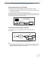
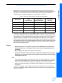
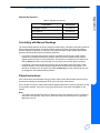
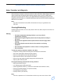
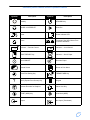
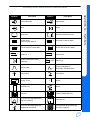
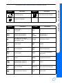
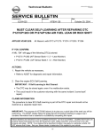
Ambulatory Blood Pressure
Monitors
90207/90217
Operations Manual
070-0137-03 Rev. K
©2005 Spacelabs Medical, Inc.
All rights reserved. Contents of this publication may not be reproduced in any form without the written permission of
Spacelabs Medical. Products of Spacelabs Medical are covered by U.S. and foreign patents and/or pending patents.
Printed in U.S.A. Specifications and price change privileges are reserved.
Spacelabs Medical considers itself responsible for the effects on safety, reliability and performance of the equipment
only if:
•
assembly operations, re-adjustments, modifications or repairs are carried out by persons authorized by
Spacelabs Medical, and
•
the electrical installation of the relevant room complies with the requirements of the standard in force, and
•
the equipment is used in accordance with the operations manual.
Spacelabs Medical will make available, on request, such circuit diagrams, component part lists, descriptions,
calibration instructions or other information which will assist appropriately qualified technical personnel to repair those
parts of the equipment which are classified by Spacelabs Medical as field repairable.
Spacelabs Medical is committed to providing comprehensive customer support beginning with your initial inquiry
through purchase, training, and service for the life of your Spacelabs Medical equipment.
CORPORATE OFFICES
U.S.A.
Spacelabs Medical, Inc.
5150 220th Ave SE
Issaquah, WA 98029
Telephone: 425-657-7200
Telephone: 800-522-7025
Fax: 425-657-7212
Authorized EC Representative UNITED KINGDOM
Spacelabs Medical Ltd.
Basepoint Business Centre
Metcalf Way, Crawley
West Sussex RH11 7XX
Telephone: 44 (0) 845 6017224
Fax: 44 (0) 845 6017225
BirthNet, Clinical Browser, Data Shuttle, Flexport, Intesys, Mermaid, MOM, Multiview, PCIS, PCMS, PrintMaster,
Quicknet, Sensorwatch, TRU-CAP, TRU-CUFF, TruLink, Ultralite, Ultraview, Ultraview Care Network, Ultraview Clinical
Messenger, Ultraview Digital Telemetry, Ultraview SL, Uni-Pouch, UCW, Varitrend and WinDNA are trademarks of
Spacelabs Medical, Inc.
Other brands and product names are trademarks of their respective owners.
Caution
Rx
Only
!
US Federal law restricts the devices documented herein to sale by, or on the order of, a
physician.
Before use, carefully read the instructions, including all warnings and cautions.
Table of Contents
Contents
Page
Operation
Overview. . . . . . . . . . . . . . . . . . . . . . . . . . . . . . . . . . . . . . . . . . . . . . . . . . . . . . . . . . . . . . . . . . . . . . . . . . . . . . . . . 1-1
ABP Monitor . . . . . . . . . . . . . . . . . . . . . . . . . . . . . . . . . . . . . . . . . . . . . . . . . . . . . . . . . . . . . . . . . . . . . . . . . . . . 1-1
Replacing the Batteries . . . . . . . . . . . . . . . . . . . . . . . . . . . . . . . . . . . . . . . . . . . . . . . . . . . . . . . . . . . . . . . . . . . . 1-2
Main Battery Replacement . . . . . . . . . . . . . . . . . . . . . . . . . . . . . . . . . . . . . . . . . . . . . . . . . . . . . . . . . . . . . . . . . 1-2
Lithium Battery Replacement (90207 only) . . . . . . . . . . . . . . . . . . . . . . . . . . . . . . . . . . . . . . . . . . . . . . . . . . . . . 1-3
Initializing the Monitor . . . . . . . . . . . . . . . . . . . . . . . . . . . . . . . . . . . . . . . . . . . . . . . . . . . . . . . . . . . . . . . . . . . . . 1-3
Connecting Directly to a Local Report Generator . . . . . . . . . . . . . . . . . . . . . . . . . . . . . . . . . . . . . . . . . . . . . . . . 1-3
Connecting Directly to the PC Interface . . . . . . . . . . . . . . . . . . . . . . . . . . . . . . . . . . . . . . . . . . . . . . . . . . . . . . . 1-4
Connecting to the Base Station via Modem . . . . . . . . . . . . . . . . . . . . . . . . . . . . . . . . . . . . . . . . . . . . . . . . . . . . 1-4
Office Check Mode . . . . . . . . . . . . . . . . . . . . . . . . . . . . . . . . . . . . . . . . . . . . . . . . . . . . . . . . . . . . . . . . . . . . . . . 1-7
Preparing the Patient and Precautions for Use . . . . . . . . . . . . . . . . . . . . . . . . . . . . . . . . . . . . . . . . . . . . . . . . . . . 1-8
Using Cuff Support . . . . . . . . . . . . . . . . . . . . . . . . . . . . . . . . . . . . . . . . . . . . . . . . . . . . . . . . . . . . . . . . . . . . . . 1-10
Correlating with Manual Readings . . . . . . . . . . . . . . . . . . . . . . . . . . . . . . . . . . . . . . . . . . . . . . . . . . . . . . . . . . 1-11
Patient Instructions . . . . . . . . . . . . . . . . . . . . . . . . . . . . . . . . . . . . . . . . . . . . . . . . . . . . . . . . . . . . . . . . . . . . . . 1-11
Data Transfer and Reports . . . . . . . . . . . . . . . . . . . . . . . . . . . . . . . . . . . . . . . . . . . . . . . . . . . . . . . . . . . . . . . . . . 1-12
Cleaning/Disinfecting . . . . . . . . . . . . . . . . . . . . . . . . . . . . . . . . . . . . . . . . . . . . . . . . . . . . . . . . . . . . . . . . . . . . 1-12
Cleaning the Cuff and Carrying Pouch . . . . . . . . . . . . . . . . . . . . . . . . . . . . . . . . . . . . . . . . . . . . . . . . . . . . . . . 1-13
Removing/Installing the Bladder . . . . . . . . . . . . . . . . . . . . . . . . . . . . . . . . . . . . . . . . . . . . . . . . . . . . . . . . . . . . 1-13
Event Codes . . . . . . . . . . . . . . . . . . . . . . . . . . . . . . . . . . . . . . . . . . . . . . . . . . . . . . . . . . . . . . . . . . . . . . . . . . . . . 1-14
Accuracy
Checking Accuracy . . . . . . . . . . . . . . . . . . . . . . . . . . . . . . . . . . . . . . . . . . . . . . . . . . . . . . . . . . . . . . . . . . . . . . . . . 2-1
Required Equipment . . . . . . . . . . . . . . . . . . . . . . . . . . . . . . . . . . . . . . . . . . . . . . . . . . . . . . . . . . . . . . . . . . . . . . 2-1
Accuracy Procedure . . . . . . . . . . . . . . . . . . . . . . . . . . . . . . . . . . . . . . . . . . . . . . . . . . . . . . . . . . . . . . . . . . . . . . 2-2
Troubleshooting
Problem Solving Checklist . . . . . . . . . . . . . . . . . . . . . . . . . . . . . . . . . . . . . . . . . . . . . . . . . . . . . . . . . . . . . . . . . . . 3-1
Servicing . . . . . . . . . . . . . . . . . . . . . . . . . . . . . . . . . . . . . . . . . . . . . . . . . . . . . . . . . . . . . . . . . . . . . . . . . . . . . . . . . 3-2
Appendix A — Symbols
i
Operation
Contents
Overview . . . . . . . . . . . . . . . . . . . . . . . . . . . . . . . . . . . . . . . . . . . . . . . . . . . . . . . . . . . 1
Preparing the Patient and Precautions for Use . . . . . . . . . . . . . . . . . . . . . . . . . . . . . . 8
Data Transfer and Reports . . . . . . . . . . . . . . . . . . . . . . . . . . . . . . . . . . . . . . . . . . . . 12
Event Codes . . . . . . . . . . . . . . . . . . . . . . . . . . . . . . . . . . . . . . . . . . . . . . . . . . . . . . . 14
Overview
The Spacelabs Medical Models 90207 and 90217 Ambulatory Blood Pressure (ABP) monitors are
small, lightweight, battery-powered monitors designed to take blood pressure and heart rate
measurements for 24 or 48 hours, or for longer periods of time.
These measurements are recorded in the monitors and may be transferred to an ABP Analysis
System (FT1000A/FT2000A or equivalent), the personal computer (PC) interface, the base
station, or a report generator for data analysis, report printing, and archiving.
Each monitor and base station can operate in a Direct Connect mode (when both units are in the
same location) or in a Remote Connection mode (using modems).
ABP Monitor
The monitors have the following features:
•
Four-digit liquid crystal display (LCD)
•
Battery powered
•
Serial communications port
•
Power ON/OFF switch
•
Reading START/STOP button
•
Blood pressure cuff
The monitors are carried in pouches that are strapped and/or belted to the side of the patient.
Blood pressure and heart rate measurements are taken using a blood pressure cuff attached to
the patient's arm. This information is recorded in the monitors and can be transferred over a
modem link or by direct connection between the monitors and one of the ABP analysis systems.
The monitors can be programmed to either activate or deactivate the following features:
•
Display the cuff pressure at each bleed step.
•
Display the systole, diastole, and heart rate at the end of each measurement.
•
Bleed to 40 mmHg rather than stopping at the diastolic value.
•
Beep before and after each reading.
Front Panel
The 90207 and 90217 monitor front panels include the LCD display, cuff hose connector, and a
START/STOP switch.
1-1
Ambulatory Blood Pressure Monitors Operations Manual
Rear Panel
The rear panels of both monitors contain program input and data output communication ports. On
the 90207, the power ON/OFF switch is also located on the rear panel. On the 90217, the ON/OFF
switch is located on the top panel.
Replacing the Batteries
“AA” batteries provide the main power source for both monitors. The 90207 monitor uses four
batteries, and the 90217 monitor uses three batteries. These batteries should be replaced or
recharged before the start of each patient monitoring session. Use either alkaline or NiCad
batteries.
The 90207 monitor uses a lithium battery (P/N 146-0008-xx) to back up the monitor memory and
should be replaced periodically. The 90217 monitor backup battery should not require
replacement.
Main Battery Replacement
Note:
If the main “AA” batteries must be replaced during patient monitoring, this replacement must
be accomplished within one minute to ensure successful resumption of the test (90207 only).
1 Power the monitor OFF, and remove the door over the battery compartment.
2 Replace the “AA” alkaline or NiCad batteries, being careful to observe polarities.
Caution
•
The monitor will not operate if the alkaline, nickel cadmium, or lithium batteries are
incorrectly installed. If the monitor is going to be stored for an extended period of
time, remove the batteries to prevent the possibility of leakage or discharge.
•
Spacelabs Medical is not responsible for product damage incurred as a result of
“AA” battery leakage. In the event your monitor has been damaged by a leaking
battery, contact the battery manufacturer for any recoverable repair or replacement
costs. Spacelabs Medical will assist you in determining those costs.
3 Gently replace the battery cover and secure the latch.
4 Power the monitor ON. Check that the LCD display is ON. If there is no display, power the
monitor OFF and review the problem-solving checklist in Troubleshooting on page 3-1.
1-2
Ambulatory Blood Pressure Monitors Operations Manual
The lithium battery is located in the battery compartment under a pry-off cover to the right of the
AA batteries.
1 Power the monitor OFF, and remove the door over the battery compartment.
2 Remove the pry-off cover, and note the polarity of the battery and socket indicators.
3 Remove the old lithium battery by carefully prying it out. Curved forceps are recommended.
4 Install the new lithium battery and replace the pry-off cover. The underside of this cover is
divided into two unequal-sized compartments. Install the cover with the smaller compartment
oriented over the lithium battery.
5 Gently replace the battery compartment cover and secure the latch.
Note:
Once the lithium battery has been completely discharged, it is considered non-hazardous and
may be safely discarded.
Initializing the Monitor
The ABP monitors must be initialized prior to the start of patient monitoring. Initialization specifies
the monitoring period, patient information, time format, measurement interval, monitor tone
ON/OFF during selected periods, event code display, and whether or not to display pressure
values. To initialize the monitor, connect it to one of the following analysis systems.
Connecting Directly to a Local Report Generator
For a direct connection to the 90207 or to the 90217 monitor, place the monitor into the chute on
the Report Generator (Model 90239A or equivalent), as displayed in Figure 1-1.
LOCAL REPORT CONFIGURATION
Figure 1-1: Report Generator
1-3
Operation
Lithium Battery Replacement (90207 only)
Ambulatory Blood Pressure Monitors Operations Manual
Connecting Directly to the PC Interface
For a direct connection to a PC-compatible computer via a Model 90121 or 92506:
1 Connect one end of the ABP interface cable to the serial port on the computer where the 90121
or 92506 software is installed.
2 Connect the other end of the interface cable to the ABP monitor.
Refer to the 90121 ABP Report Management System Operations Manual (P/N 070-0529-xx) or the
92506 ABP Report Management System Client Application Operations Manual (P/N 070-0932-xx)
for more information on the report management system.
Computer System with
90121 or 92506 ABP software
cable to serial port
ABP
Monitor
Figure 1-2: PC interface direct connect configuration
Connecting to the Base Station via Modem
For a modem connection to a remote IBM XT/AT/PS2 (or equivalent) base station,
refer to Figure 1-3.
to
base
station
modem
public
telephone
network
cable to
serial port
ABP
Monitor
modem
phone
Figure 1-3: Modem connection configuration
Note:
The actual initialization procedure is discussed in the 90121 ABP Report Management System
Operations Manual (P/N 070-0529-xx) and in the 92506 ABP Report Management System
Client Application Operations Manual (P/N 070-0932-xx).
1-4
Ambulatory Blood Pressure Monitors Operations Manual
The 90207 and 90217 monitors operate Hayes-compatible modems only. You can identify your
model type by plugging the communications cable into your 90207/90217 monitor and looking at
the numbers on the display. The acceptable modem types and maximum speeds of 90207/90217
monitors are summarized below:
Table 1: 90207/90217 Acceptable Modem Speeds
Max Speed
Modems
Accepted
Display
older 90207
1200
1200 only
9999
90207-Q
1200
any Hayes
1999/9999
up to 9600
up to 9600
2999/9999
9600
any Hayes
0999/9999
Model Type
older 90217
90217-Q
Connection Procedure
1 Set the switches on the modem if you are using an older 90207 monitor with a 1200 modem,
as follows:
Switch Number
Setting at Monitor Site
1
2
3
4
5
6
7
8
9
10
down
up
down
down
down
up
up
down
up
up
2 Connect the serial port cable (P/N 012-0096-00) between the monitor and the modem.
Note:
If call waiting or call forwarding are options on a telephone used to transfer data, ensure that
both are deactivated. Otherwise modem communications may be interrupted. In addition,
telephone systems such as CBX or PBX can cause interference with the modem, or the
modem can cause interference with the switching system.
1-5
Operation
Modem Speed and Compatibility Issues
Ambulatory Blood Pressure Monitors Operations Manual
To initialize the monitor for remote connection:
1 Contact the base station by telephone (for remote operation only).
2 Ask the base station operator to initialize the monitor. Give the following information to the
operator:
•
Patient's name
•
Patient ID number
•
Whether monitor display is to be active or not
•
Time of day (12- or 24-hour format)
•
Whether to display measurement (systolic/diastolic and heart rate)
•
Multiple or single cycle times. If using a single cycle for the 24-hour monitoring period,
indicate the cycle interval and whether the tone is ON or OFF. For multiple cycle times,
specify each cycle interval and whether the tone is ON or OFF for each cycle.
•
Any other information the base station operator may request
The base station operator will enter the patient information in the computer.
3 Prepare the monitor to receive the patient data from the base station.
•
Power ON the modem.
•
When instructed by the base station operator, power ON the ABP monitor.
Note:
The modem link must be established within 10 to 20 seconds for the 90207, and within
45 seconds for the 90217. If this does not occur, power the monitor OFF and then ON again to
retry establishing the link.
When the transfer of information is complete, the ABP monitor will beep. Voice communication is
restored after the monitor beeps.
•
Power OFF the monitor and disconnect the monitor from the modem.
•
If a direct connection between the monitor and the base station is used, power OFF the
monitor and then disconnect it from the ABP data interface unit.
To transfer readings from the monitor to the base station:
1 Contact the base station by telephone (for remote operation only).
2 Ask the base station operator to read the monitor. Give the following information to the operator:
•
Patient's name
•
Patient ID number
•
Any other information the base station operator may request
The base station operator will enter the patient information in the computer. (If the monitor is in
a remote location, the operator turns the base station modem ON.)
3 Prepare the monitor to transfer data to the base station.
•
Power ON the modem.
•
When instructed by the base station operator, power ON the ABP monitor
(for remote operation only).
Note:
The modem link must be established within 10 to 15 seconds for the 90207, and within
45 seconds for the 90217. If this does not occur, power OFF the monitor and return to step 1.
1-6
Ambulatory Blood Pressure Monitors Operations Manual
Power OFF the monitor. Disconnect the monitor from the modem.
Modem Indicator Lights
Modem indicators at the local modem are lit, flashing, or unlit depending on the stage of operation.
When the monitor is powered ON, the RD (Receive Data) and SD (Send Data) lights will flash for
several seconds. The OH (On Hook) indicator becomes lit when the monitor starts communicating
with the remote modem. When the modems connect, the CD (Carrier Detect) is lit. The SD and RD
lights flash as data is being transferred.
After the transmission is complete and the monitor is powered OFF, the HS, TR, and MR
indicators will always remain lit at the local modem.
Setup Test
Note:
Verify that the cable connections are secure.
Power ON the ABP monitor. It will display "9999." While the monitor is being read or initialized, the
digits will change to indicate that communication is taking place between the monitor and the
analysis system. When communication is complete, the digits will no longer change.
Office Check Mode
The monitor automatically enters an Office Check mode for the first five measurements
immediately following initialization. This allows you to verify the performance of the monitor on an
individual patient without the need for re-initialization to reset the display features.
While in the Office Check mode, the monitor operates as follows:
•
Displays the cuff pressure on each bleed step.
•
Displays systole, diastole, and heart rate at the end of the measurement.
•
Bleeds one step below the diastolic value as determined by the monitor.
Terminating Office Check Mode
For the 90207 monitor (versions earlier than 2.14), press the START/STOP key twice to cancel
each of the remaining readings. The Office Check mode is terminated when the sum of the
canceled and successful measurements equals five.
For the 90217 and the 90207 monitors (versions 2.14 and later), press the START/STOP key
twice to cancel a single blood pressure reading. The Office Check mode is terminated when a
blood pressure reading is canceled.
Any event that prevents a successful blood pressure measurement (other than a manual cancel) is
not counted as one of the five Office Check mode readings.
1-7
Operation
When the transfer of information is complete, the ABP monitor will beep. Voice communication is
restored after the monitor beeps.
Ambulatory Blood Pressure Monitors Operations Manual
Reinstating Office Check Mode
The Office Check mode may be reinstated in the 90217 and the 90207 monitors (versions 2.14
and later).
To reinstate the Office Check mode without initialization of the monitor:
1 Power ON the monitor.
2 Press and hold the START/STOP key when the version displays on the LCD.
3 Release the START/STOP key when EC03 displays on the LCD.
An EC13 will be logged to indicate the time at which the office Office Check was reinstated. The
Office Check mode will be enabled for five additional successful measurements.
Preparing the Patient and Precautions for Use
Note:
• Blood pressure measurements determined with this device are equivalent to those
obtained by a trained observer using the cuff/stethoscope auscultation method, within the
limits prescribed by the American National Standard, Electronic, or automated
sphygmomanometers.
- The fifth Korotkoff sound was used to determine overall efficiency.
• As in manual auscultatory methods, accurate readings may not always be achieved under
some conditions. Patient movement, the position of the cuff relative to the level of the
heart, extreme heart rates and blood pressures, various arrhythmias, and the subject’s
physiological condition and other factors may hinder an accurate reading. Vibration, such
as that in a moving automobile, is an environmental problem that may affect readings.
• When some of the above factors prevent an accurate reading, an event code is provided to
indicate the reason for the missed blood pressure reading. When only a single blood
pressure parameter (systole, diastole, or mean arterial pressure) is obscured and the
other two parameters are measured, the obscured parameter may be replaced with a
computed value.
• If such a value is computed in the 90217 monitor, it appears on the report in angle
brackets, e.g., < value >. On the monitor display, dashes are displayed instead of the
estimated value. The ratio used in the formula is determined by the previous successful
measurements of the pressure, rather than a fixed ratio.
• Consult a physician for interpretation of pressure measurements.
After the monitor has been initialized, prepare the patient for monitoring as follows:
1 Power ON the monitor (wait for the monitor to perform self-tests). When the LCD displays the
current time, the monitor is ready for operation.
2 Strap the monitor to the patient’s hip opposite the side on which the cuff is worn. Secure the
monitor using the patient's own belt or the ABP pouch strapped over the opposite shoulder.
When using the shoulder strap, use the belt supplied with the monitor or the patient’s belt to
provide additional security.
1-8
Ambulatory Blood Pressure Monitors Operations Manual
Table 2: Cuff Sizes, Circumference Ranges and Part Numbers
Description
Limb
Circumference
Part Number
Quick-Disconnect
Part Number
Luer-Lock
Pediatric Cuff
12 to 20 cm
015-0118-01Q
015-0118-01
Small Adult Cuff
17 to 26 cm
015-0067-01Q
015-0067-01
Adult Cuff
24 to 32 cm
015-0068-02Q
015-0068-02
Large Adult Cuff
32 to 42 cm
016-0077-01Q
016-0077-01
Extra-large Adult Cuff
38 to 50 cm
016-0109-01Q
016-0109-01
4 Position the cuff so that the center of the inflatable bladder is directly over the brachial artery.
The center of the bladder location is marked on the outside of the cuff. Once the proper position
is determined, the cuff must be tightened to ensure that it is equally snug at the top and bottom
edges and that it is not kinked. This is especially important on larger arms. Insert a finger
between the cuff and the limb to ensure it is not too tight. It may be necessary to wrap the cuff
with its tail at an angle to achieve uniform tightness. If the cuff is not equally snug at the top and
bottom edges, the number of readings available will be limited and the monitor may indicate
that the cuff is improperly applied.
Caution
•
Avoid compression or restriction of pressure in the NIBP patient connector tubes.
Check that operation of the equipment does not result in prolonged impairment of
circulation.
•
Do not apply cuff to areas of breached or injured skin.
•
This product contains natural latex rubber components to which some people may
be allergic. These components include the bladder and the first four inches of tubing
extending from the cuff.
Note:
• Use only Spacelabs Medical cuffs with this monitor. Using other manufacturer’s cuffs may
result in inaccurate readings, even if the manufacturer’s recommended size is observed.
• If the cuff is too small, pressure readings may be falsely high; if a cuff is too large it
produces a falsely low reading. The bladder can be positioned in the cuff for either the left
or right arm.
Once the cuff is applied, the arm should be relaxed at the patient's side. To avoid reading
errors due to hydrostatic pressure differences, the level of the cuff on the arm should be near
the level of the heart.
1-9
Operation
3 Ensure the accuracy of blood pressure measurements through proper cuff selection and
application. To select the proper cuff, first measure the circumference of the limb at the point
where the cuff will be applied. Match the limb measurement to the range of appropriate
circumferences (in centimeters) specified on each cuff (refer to Table 2).
Ambulatory Blood Pressure Monitors Operations Manual
5 Lead the hose up the arm with the cuff and place it across the back of the patient. Drape the
hose so it does not cause the patient discomfort and is not pinched shut by too tight a radius.
The following graphic displays the most common positions for the cuff hose.
ALTERNATIVE #1
ALTERNATIVE #2
6 Connect the hose to the monitor.
7 Verify proper monitor operation by taking one or more blood pressure readings. Push the
START/STOP key to begin a measurement. Spacelabs Medical recommends taking three
readings in the office so that the patient becomes comfortable with operation of the monitor and
the measurement process.
8 Show the patient how to enter information in the Patient Diary. Make sure the patient knows what
to do if the cuff becomes very uncomfortable during a measurement, if it slips out of place, or if
event codes are displayed on the monitor screen (refer to Patient Instructions on page 1-11).
Also, ensure that the patient knows how to care for the monitor.
9 When you are satisfied that the monitor is operating properly, the remaining measurements in
the Office Check mode may be canceled. Refer to Office Check Mode on page 1-7.
Using Cuff Support
Note:
Keeping the blood pressure cuff in place is very important both for patient comfort and for the
accuracy of the readings. This becomes particularly challenging when the arm has
considerable taper, as is often the case with obese patients.
1 Put the large loop of the support around the opposite arm. Once the cuff is successfully applied
to the patient, adjust the length so that the junction of the straps fits well back on the shoulder
towards the neck.
2 Fasten the rear short strap to the rear of the armpit. Be careful to clip to the material only and
not to the bladder.
3 Fasten the front strap to the top layer of the cuff material at the location where the hose exits the
cuff. Adjust the length of these straps to apply a minor amount of tension to hold the cuff in the
correct position.
1-10
Ambulatory Blood Pressure Monitors Operations Manual
Operation
Optional Accessories
Table 3: Optional Accessories
Accessories
Part Number
Cuff Support Harness
015-0070-xx
Service Manual
070-0502-xx
Quick Disconnect Coupling
712-0794-00
Male Quick Disconnect to Luer Adapter
712-0773-00
Correlating with Manual Readings
The monitor bleeds pressure in discrete steps (not continuously), using the oscillometric method of
blood pressure determination. If manual pressure readings are taken simultaneously with the
monitor readings, interpolation is required to accurately correlate monitor systolic and diastolic
pressure values with the manual auscultatory pressures.
•
For systole, record the first pressure at which a Korotkoff sound is heard. Actual systolic
pressure is somewhere between the pressure when the sound is heard and the previous
(higher) pressure where no sound was heard. The interval of uncertainty can be reduced by
half by adding one half of the bleed step size (4 mmHg) to the manual systolic pressure.
•
For diastole, record the cuff pressure at which the last Korotkoff sound was heard. Actual
diastolic pressure is somewhere between that pressure and the next lower pressure. The
interval of uncertainty can be reduced by half by subtracting one half of the bleed step size
(4 mmHg) from the manual diastolic pressure.
Patient Instructions
If the cuff becomes uncomfortable during a reading, make certain that the patient knows how to
terminate the readings by pressing the STOP key on the front of the monitor.
If the cuff slips out of place, make certain that the patient knows how to correctly reposition the cuff
for successful readings. If the cuff is not properly positioned, event codes may appear on the
monitor.
Note:
The patient should make every effort to keep the monitor dry. However, there is no hazard if
the monitor does get wet. If this occurs, power the monitor OFF and return it to Spacelabs
Medical for service.
1-11
Ambulatory Blood Pressure Monitors Operations Manual
Data Transfer and Reports
After monitoring is complete, connect the monitor to either a PC Direct or Base Station interface to
transmit patient data and generate blood pressure reports. Refer to the 90121 ABP Report
Management System (P/N 070-0529-xx), the 92506 ABP Report Management System Client
Application (P/N 070-0932-xx), or the 90239 ABP Report Generator (P/N 070-0399-xx) Operations
Manuals for more details.
Note:
Any pulse rate obtained from the ABP cuff should be used only as a guideline for the
heart rate.
Cleaning/Disinfecting
Visually inspect the monitor, air hose, and pressure cuff for dirt, debris, frayed or worn areas, etc.,
prior to patient use.
Warning
•
Use only recommended cleaning solutions, or you may void the
manufacturer’s warranty.
•
Harsh chemical agents degrade plastics and will compromise the safety of
the device.
•
Disconnect the equipment from the patient and the electrical supply before
cleaning.
•
Do not allow liquid to enter the interior of the module or monitoring
equipment.
•
Do not immerse the equipment or cables in water or cleaning solutions.
•
Do not autoclave.
To clean the exterior of monitors, modules, and cables:
•
Prepare the cleaning solution according to the manufacturer’s instructions.
•
Wet a clean cloth with the selected cleaning solution.
•
Remove excess liquid from the cloth and squeeze dry.
•
Wipe exposed surfaces of the equipment and cables.
•
Remove any soap residue by gently wiping with a clean damp cloth.
•
Wipe dry with a clean dry cloth.
Use only the following recommended cleaning solutions:
•
Mild soap and water solution
•
U.S. Pharmacopoeia (USP) green soap
•
Sodium hypochlorite solution (1:10 dilution of household chlorine bleach in water)
•
Phenolic germicidal detergent (1% aqueous solution)
•
Glutaraldehyde (2.4%) (Cidex)
•
Isopropyl alcohol (70% solution)
Note:
Over time, repeated use of a chlorine bleach solution may cause some colors to fade.
1-12
Ambulatory Blood Pressure Monitors Operations Manual
Questions and concerns about cleaning issues should be directed to a Spacelabs Medical field
service engineer.
Cleaning the Cuff and Carrying Pouch
Small soiled or stained areas may be cleaned by gentle scrubbing with a sponge or cloth soaked in
a mild soap and water solution.
The cuff wrap (with the air bladder removed) and the pouch are machine washable on “delicate”
cycle only. Do not wash them in large commercial-type washers or with bed linens or gowns.
Ensure that the carrying pouch is dry before re-use.
Removing/Installing the Bladder
To remove the bladder, follow the steps listed below:
1 Using fingers only, fold or roll up the bladder inside the cuff. Do not use pencils, pens, or other
hard objects, because these may damage the bladder.
2 Remove the bladder through the hose exit opening.
Once the bladder is removed, mate together the hook-and-loop surfaces of the velcro attachment
before washing.
Re-install the bladder into the cuff wrap in reverse order. Make certain that all folds in the bladder
are removed and that the long end of the bladder fits into the long end of the cuff
(refer to Figure 1-4).
OPENING FOR
RIGHT ARM
OPENING FOR
LEFT ARM
BLADDER
(shown inserted into cuff wrap
for left arm application)
ARTERY
Figure 1-4: Bladder configuration
Note:
The cuff hose can exit from either opening in the cuff, depending on whether you plan a right
arm or left arm application.
1-13
Operation
Tape adhesive can be removed with Spacelabs Medical adhesive tape remover pads
(P/N 392196-001).
Ambulatory Blood Pressure Monitors Operations Manual
Event Codes
The monitors display an event code whenever an event prevents the monitor from successfully
completing a blood pressure measurement. The two numerical digits of the event code indicate
the reason the measurement was aborted. The table below lists event codes that are displayed on
the monitor, as well as event codes that appear on the Event Code Report.
Monitor
Report
Condition
EC00
EC10
Excess movement artifact. Frequent EC10 messages may indicate an air leak.
EC20
A) A very large number of movement artifacts
B) Heart rate arrhythmia
EC30
A) Movement artifact at mean arterial pressure
B) Heart rate arrhythmia
EC40
A) Movement artifact at asystole
B) Heart rate arrhythmia
EC50
A) Movement artifact at diastole
B) Heart rate arrhythmia
EC60
A) Movement artifact
B) Heart rate arrhythmia
EC70
Systole was found to be above the highest cuff pressure. However, this result
appears to be an error caused by motion artifact. Therefore, the cuff will not be
inflated to a higher pressure on the next measurement attempt.
EC80
A) Movement artifact
B) Heart rate arrhythmia
EC90
A) Movement artifact
B) Heart rate arrhythmia
EC11
Did not pump above the mean arterial level.
EC21
Did not pump above systolic pressure.
EC91
Systole appears higher than the selected maximum cuff pressure limit.
EC12
Did not reach initial cuff pressure. The cuff may have been improperly applied or
there may be an air leak.
EC22
Overpressure.
EC32
Overpressure.
EC42
No cuff attached.
EC01
EC02
1-14
Ambulatory Blood Pressure Monitors Operations Manual
Report
Operation
Monitor
Condition
EC52
Kinked hose.
EC62
Cuff applied too loosely.
EC82
Kinked hose.
EC03
Patient canceled reading by pressing STOP key. No retry attempt is made
following an EC03 code.
EC13
The Office Check mode has been reinstated. No retry attempt is made
following an EC13 code.
EC04
Blood pressure measurement not completed in the maximum time allowed.
Occasional EC04 messages may result from excessive patient movement.
Frequent EC04 messages would indicate an improperly applied cuff or a
monitor malfunction which requires service.
ECn4
(where n = 1 to 9) Indicates that one or more of the blood pressure results have
been corrupted and subsequently recovered. Frequent occurrence of this
message would indicate a malfunction that requires service.
EC05
The individual blood pressure result has been corrupted and cannot be
recovered.
EC03
EC04
EC15
Equipment malfunction. Return to Spacelabs Medical for service.
EC25
Monitor failed to initialize. Please initialize.
EC35
90207
At least one of the blood pressures or time readings obtained before the event
code is erroneous. Interpret all readings with caution.
90217
The monitor needs to be reinitialized.
EC05
EC45
Invalid bleed size. The monitor has automatically changed the bleed size to
8 mmHg.
EC55
An unexpected loss of power possibly caused by: a) removal of the batteries
during a blood pressure measurement, b) hardware overpressure, or c) a
hardware time-out. Frequent EC55 messages would indicate a malfunction
which requires service.
EC05 &
EC65
EC65
90207
Equipment malfunction. Return to Spacelabs Medical for service.
90217
Extremely large artifact.
EC05 &
EC75
EC75
Equipment malfunction. Return to Spacelabs Medical for service.
EC05 &
EC45
EC05 &
EC55
1-15
Ambulatory Blood Pressure Monitors Operations Manual
Monitor
EC05 &
EC85
EC05 &
EC95
Report
Condition
EC85
Equipment malfunction. Return to Spacelabs Medical for service.
EC95
Cuff pressure baseline is out of limits. The monitor should correct the baseline
automatically within 10 minutes, or it can be reset by initializing the monitor.
If initialization does not correct the condition, the monitor must be returned to
Spacelabs Medical for calibration.
EC78
Clogged connector filter.
EC18
Too few data entries to accurately determine blood pressure. This message may
indicate that the cuff is not being worn by the patient (taken off but left
connected to the monitor). The message may also indicate that motion artifacts
cause the majority of the incomplete data.
EC28
Diastole above 200 mmHg.
EC38
Pulse pressure less than 16 mmHg.
EC48
A) Movement artifact at mean arterial pressure
B) Heart rate arrhythmia
EC58
A) Movement artifact at diastole
B) Heart rate arrhythmia
EC68
Division by zero.
EC19
Contradictory instructions sent to hardware (e.g., “pump ON and valve open”).
EC29
Diastolic pressure value cannot be obtained from the data available.
EC39
90207
Systolic pressure cannot be obtained from the data available.
90217
Algorithm could not process input data quickly enough, resulting in an input
queue overflow.
EC49
90207
Mean arterial pressure cannot be obtained from the data available.
90217
This monitor must be initialized.
EC59
Heart rate value cannot be obtained from the data available.
EC69
Heart rate value cannot be obtained from the data available.
EC79
Bleed steps were too small. This may be caused by a partially obstructed air
hose. All blood pressure attempts following this message are inhibited. Attempts
can be enabled by powering the monitor OFF and then ON.
EC07
EC08
EC09
1-16
Ambulatory Blood Pressure Monitors Operations Manual
Report
Operation
Monitor
Condition
EC99
Unexpected or contradictory data (such as a negative cuff pressure).
EC16
Low battery detected prior to start of measurement.
EC26
Low battery detected after measurement started. Usually caused by the pump
drawing enough current to lower the battery voltage.
LLL
Lbb
The report does not print an event code for this condition, which is a low backup
battery. Contact Spacelabs Medical for replacement of the battery.
1-17
Accuracy
Contents
Checking Accuracy . . . . . . . . . . . . . . . . . . . . . . . . . . . . . . . . . . . . . . . . . . . . . . . . . . . 1
Checking Accuracy
Accuracy of the monitor pressure readings should be checked annually. Recalibration is
necessary only if the monitor is not within the accuracy limits.
Required Equipment
•
A full-size mercury sphygmomanometer or aneroid gauge.
Note:
Ensure the mercury sphygmomanometer or aneroid gauge is calibrated and indicates “0” with
no pressure.
•
T-tube (P/N 016-0040-00).
•
A pressure cuff and a rigid cylinder sized to fit the pressure cuff.
2-1
Ambulatory Blood Pressure Monitors Operations Manual
Accuracy Procedure
To check the accuracy of the monitor:
1 Disconnect the cuff hose from the monitor. Connect the T-tube splitter to the monitor pneumatic
connector and the sphygmomanometer.
2 Wrap the pressure cuff around the rigid cylinder, and then fasten the cuff. Connect the cuff hose
to the remaining connection on the T-tube splitter. The test setup should appear as shown
below.
712-0039-01 CALIBRATION KIT
TO MONITOR
TO SPHYGMOMONOMETER
TO CUFF/CYLINDER
)RUXVHZLWK40RQLWRU4XLFN'LVFRQQHFW&XII&DQ
&RQQHFW
WR
4
$%30RQLWRU
&RQQHFW
WR
6SK\JPRPRQRPHWHU
&RQQHFW
WR
4XLFN'LVFRQQHFW
)LWWLQJ&XII
)RUXVHZLWK0RQLWRU/XHU)LWWLQJ&XII&DQ
5HPRYH/XHU%DUE7XELQJ
&RQQHFW
WR
6SK\JPRPRQRPHWHU
5HPRYH4XLFN
'LVFRQQHFW)LWWLQJ
2-2
Ambulatory Blood Pressure Monitors Operations Manual
Note:
If the monitor pressure values fall outside the allowed tolerance, call your local Customer
Service Representative or Spacelabs Medical for servicing.
At the end of the procedure, the monitor displays an event code indicating that no dynamic
blood pressure measurements were obtained.
4 Disconnect the T-tube splitter from the monitor. Disconnect the air hose and
sphygmomanometer.
2-3
Accuracy
3 Press START/STOP on the monitor; the monitor should read approximately 165 mmHg.
Compare the readings on the monitor and the manometer as the pressure bleeds down. The
monitor reading should be within three millimeters or 2% of the manometer reading, whichever
is greater (± the accuracy of the manometer).
Troubleshooting
Contents
Problem Solving Checklist . . . . . . . . . . . . . . . . . . . . . . . . . . . . . . . . . . . . . . . . . . . . . . 1
Servicing . . . . . . . . . . . . . . . . . . . . . . . . . . . . . . . . . . . . . . . . . . . . . . . . . . . . . . . . . . . 2
Problem Solving Checklist
Problem
Possible Cause
Solution
Data not retained.
Replace backup battery.
Low or no power.
Check the batteries for a full
charge; if needed, replace or
recharge the batteries.
May be one of the following:
time-out, no reading due to air
leak in the system, improper cuff
size, cuff not properly attached to
the monitor.
Isolate cause and correct.
Monitor displays “LLL”
and alarm sounds
Low main battery condition.
Power OFF the monitor
immediately. Replace batteries
within 60 seconds after removal
to continue monitoring.
Monitor displays event
code “Lbb” during
self-testing
(90207 only)
Low backup battery condition.
Replace backup battery before
continuing.
Cuff placed on the patient too
tightly.
Reposition the cuff.
Air pump staying on too long.
Return monitor to Spacelabs
Medical for service.
Cuff placed on the patient too
loosely.
Reposition the cuff.
Air pump not staying on long
enough.
Return monitor to Spacelabs
Medical for service.
Batteries removed for more than
one minute (90207 only).
Re-initialize monitor.
Monitor display is
incorrect
Cuff too tight
Cuff too loose
Incorrect time
displayed
3-1
Ambulatory Blood Pressure Monitors Operations Manual
Servicing
There is a 12-month warranty on this product.
Field service for the ABP monitor is limited to replacing batteries and accessories. If other repair is
required, return the monitor to Spacelabs Medical. Contact your Spacelabs Medical Customer
Service Representative for shipping details.
Caution
Any attempt to perform service or repair to the monitor will result in cancellation of the
warranty.
3-2
Appendix A — Symbols
The following list of international and safety symbols describes all symbols used on Spacelabs Medical
products. No one product contains every symbol.
Symbol
Description
Symbol
Description
HELP Key
Keyboard Connection
SPECIAL FUNCTIONS Key
Mouse Connection
RECORD Key
START/STOP Key
NORMAL SCREEN Key
START/STOP
MONITOR SETUP Key
STOP or CANCEL Key
ALARMS Key
CONTINUE Key
PREVIOUS MENU Key
ENTER Key
ON — Power Connection to Mains
OFF — Power Disconnection from
Mains
ON Position for Push Button Power
Switch
OFF Position for Push Button Power
Switch
On Direction
ON/OFF
Television; Video Display
Video Output
ON — Part of the Instrument Only
OFF — Part of the Instrument Only
A-1
Ambulatory Blood Pressure Monitors Operations Manual
Symbol
Description
Description
Standby
STANDBY Key
PAUSE or INTERRUPT
Slow Run
Reset
Power Indicator LED
Alarm
Temporary Shut Off of Alarm Tone
or Screen Indicators
Indicator — Remote Control
Indicator — Local Control
PRINT REPORT Key
Indicator — Out of Paper
Partial ON/OFF
Recorder Paper
Normal Screen
?
Symbol
1
2
3
1
2
3
Return to Prior Menu
Clock/Time Setting Key
TREND/TIMER Key
HELP (Explain Prior Screen) Key
Keypad
Activate Recorder for Graphics
Indoor Use Only
START (NIBP) Key
Auto Mode (NIBP)
Output
No Output (Terminated)
A-2
Ambulatory Blood Pressure Monitors Operations Manual
1
2
3
Input/Output
Input
Reset
Menu Keys
Waveform/Parameter Keys
B
Access Special Function Menu
1
Serial Port 1
1
2
3
A
1
2
3
Set Initial Conditions Menu
Return Unit to Monitor Mode
2
External marker push button
connection
SDLC
Serial Port 2
SDLC Port
Arterial Pulse
Electrocardiograph or
Defibrillator Synchronization
Gas Exhaust
Foot Switch
Enlarge, Zoom
12,200 m
Description
Data Input/Output
Monitor Setup
Select Program Options
1
2
3
Symbol
Description
Appendix A — Symbols
Symbol
x
Delete
PCMCIA Card
Event
Keep Dry
Fragile; Handle with Care
Environmental Shipping/Storage
Altitude Limitations
This Way Up
Environmental Shipping/Storage
Temperature Limitations
Environmental Shipping/Storage
Humidity Limitations
A-3
Ambulatory Blood Pressure Monitors Operations Manual
Symbol
Description
Symbol
Description
Open Padlock
Closed Padlock
Down Arrow
Up Arrow
Hard Drive
Power Indicator LED
Antenna
Mermaid Connector
Microphone
Omnidirectional Microphone
Audio Output, Speaker
Activate Telemetry Recorder
Network Connection
Universal Serial Bus
Gas Sampling Port
Gas Return Port
Remote Alarm; Nurse Alert
Nurse Call
Battery Status
Low Battery
Battery
Replace only with the appropriate
battery.
Replace only with the appropriate
battery.
(+ / - signs may be reversed)
All batteries should be disposed of
properly to protect the environment.
Lithium batteries should be fully
discharged before disposal.
Batteries such as lead-acid (Pb) and
nickel-cadmium (Ni-Cd) must be
recycled. Please follow your internal
procedures and or local (provincial)
laws regarding disposal or recycling.
Caution - hazardous voltages. To
reduce risk of electric shock, do not
remove the cover or back. Refer
servicing to a qualified field service
engineer (U.S.A.).
DANGER - High Voltage
(International)
A-4
Ambulatory Blood Pressure Monitors Operations Manual
Description
Symbol
Appendix A — Symbols
Symbol
Description
Protective Earth Ground
Functional Earth Ground
Replace Fuse Only as Marked
Fuse
Power supply jack polarity.
(+ / - signs may be reversed)
Equipotentiality Terminal
Alternating Current
Direct Current
Both Direct and Alternating Current
AC/DC Input
A
Amperes
Hz
Hertz
V
Volts
W
Watts
IEC 60601-1 Type B equipment.
The unit displaying this symbol
contains an adequate degree of
protection against electric shock.
IEC 60601-1 Class II equipment,
double-isolated. The unit displaying
this symbol does not require a
grounded outlet.
IEC 60601-1 Type BF equipment
which is defibrillator-proof. The unit
displaying this symbol contains an
F-type isolated (floating) patientapplied part which contains an
adequate degree of protection
against electric shock, and is
defibrillator-proof.
IEC 60601-1 Type BF equipment.
The unit displaying this symbol
contains an F-type isolated (floating)
patient-applied part providing an
adequate degree of protection
against electric shock.
IEC 60601-1 Type CF equipment.
The unit displaying this symbol
contains an F-type isolated (floating)
patient-applied part providing a high
degree of protection against electric
shock, and is defibrillator-proof.
IEC 60601-1 Type CF equipment.
The unit displaying this symbol
contains an F-type isolated (floating)
patient-applied part providing a high
degree of protection against electric
shock.
Loop Filter
Adult NIBP
A-5
Ambulatory Blood Pressure Monitors Operations Manual
Symbol
Description
Symbol
®
ETL Laboratory Approved
US
Note
Warning
LATEX
Canadian Standards Association
Approved
Risk of Explosion if Used in the
Presence of Flammable Anesthetics
!
Operates on Non-Harmonized
Radio Frequencies in Europe
Note
!
Attention - Consult Operations or
Service Manual for Description
Warning About Potential Danger to
Human Beings
Caution
Caution About Potential Danger to a
Device
Noninvasive Blood Pressure (NIBP),
Neonate
Fetal Monitor Connection (Analog)
Fetal Monitor Connection
RS-232 (Digital)
Physiological Monitor Connection
RS-232 (Digital)
Happy Face
Sad Face
Magnifying Glass
Compression
File Cabinet
List of Rooms
Arrows
Printer
Recycle
Service Message
Latex-free
2
Radio transmitting device; elevated
levels of non-ionizing radiation
LOT
Description
Batch Code
Do Not Reuse; Single Use Only
Reusable
REF
Catalog Number
A-6
Ambulatory Blood Pressure Monitors Operations Manual
Description
Date of Manufacture
NV
X
Symbol
NE
2
Appendix A — Symbols
Symbol
Description
Nellcor Oxisensor II Compatible
Novametrix Compatible
Abbreviations used as symbols are shown below.
Symbol
Description
Symbol
Description
1 - 32
Access Codes
1 Through 32
AIR
Air
ANT 1
ANT 2
Diversity Antenna System 1
Diversity Antenna System 2
Arr1
ArrNet2
Arrhythmia Net 1
Arrhythmia Net 2
CH
ch
EEG, EMG, or ECG Channel
EEG Channels - CH1, CH2, CH3, CH4
EMG Channel - CH5
cmH2O
Centimeters of Water
C.O.
CO
co
Cardiac Output
DIA
dia
Diastolic
ECG
ecg
Electrocardiogram
EEG
eeg
Electroencephalogram
EMG
emg
Electromyogram
ESIS
Electrosurgical Interference
Suppression
EXT
External
FECG
Fetal Electrocardiogram
FHR1
FHR2
Fetal Heart Rate, Channel 1
Fetal Heart Rate, Channel 2
GND
gnd
Ground
HLO
hlo
High-Level Output
Multiview
Multi-Lead Electrocardiogram
NIBP
nibp
Noninvasive Blood Pressure
N 2O
Nitrous Oxide
A-7
Ambulatory Blood Pressure Monitors Operations Manual
Symbol
Description
Symbol
Description
O2
Oxygen
PRESS
press
PRS
Pressure
RESP
resp
Respiration
SDLC
Synchronous Data Link Control
SPO2
SpO2
SpO2
SaO2
Arterial Oxygen Saturation
as Measured by Pulse Oximetry
SVO2
SvO2
Mixed Venous Oxygen Saturation
SvO2
Systolic
T1
T2
T3
T4
Temperature 1
Temperature 2
Temperature 3
Temperature 4
TEMP
temp
Temperature
UA
Uterine Activity or Umbilical Artery
VAC
Vacuum Connection
SYS
sys
A-8