1
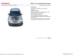
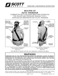
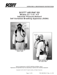
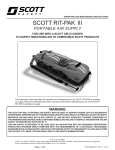
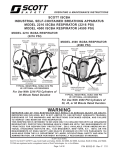
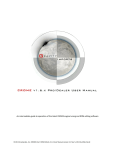
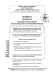
Module 8 Fuel Delivery System Author: Grant Swaim E-mail: [email protected] URL: www.tech2tech.net Phone: (336) 632-9882 Fax: (336) 632-9688 Postal Address: Tech-2-Tech Website PO Box 18443 Greensboro, NC 27419 Physical Address: 220-4 Swing Rd Greensboro, NC 27409 Last Update: April 2000 IMPORTANT - READ ! Do not read or study this information unless you agree to the following conditions: The information in this training module is the intellectual property of N. Grant Swaim and is copyrighted by Sure Seal Products Inc. Subscribers to the Tech-2-Tech website, and persons participating in Tech-2-Tech’s on-line training program are entitled to read this material on-line. You may also click on the “save” icon on the Acrobat viewer and save a copy to your local computer. You may save a copy of this file on one computer and it must be viewed from that one computer. You may also print one copy of this file for your viewing. If the printed copy becomes illegible, or lost, an additional copy may be printed. Tech-2-Tech offers the following training modules in printed manual, CD-ROM, and on-line formats. PGMFI Training Modules • • • • • • • • • • • • • • • • • • • • • • • The PGMFI System Overview—Part 1 The PGMFI System Overview—Part 2 PGMFI Flash Type DTCs Inputs / Outputs—Part 1 Inputs / Outputs—Part 2 Engine Control Module Air Flow / MAP Sensor—Base Inj Pulse Width Fuel Delivery System Closed Loop Strategies—Theory Closed Loop Strategies—Case Studies Thermistor Inputs Throttle Position Sensor EGR Valve Lift Sensor MAP / BARO Sensor Ignition Inputs Vehicle Speed Sensor Oxygen Sensor Lean Air Fuel Sensor Miscellaneous Input Signals Fuel Injectors—Multi-Port Injection Fuel Injectors—Dual Point Injection Ignition System—Outputs Idle Air Control Valve OBD-II Training Modules • • • • • • • • • • • • • • • On Board Diagnostics—General Overview Diagnostic Trouble Codes MIL / Freeze Frame Scan Tool Scan Tool—Advanced Monitor Tests—Overview Comprehensive Component Monitor Catalyst Monitor EGR Monitor Evaporative Monitor Fuel System Monitor Misfire Monitor Oxygen Sensor Monitor Oxygen Sensor Heater Monitor “P” Codes Miscellaneous Training Material • Glossary of Terms 2000 © - All Rights Reserved Sure Seal Products Inc - Greensboro, NC Visit Our Website: www.tech2tech.net Page 8-1 8 Fuel Delivery System 8.1 General Overview Honda uses a traditional return type fuel delivery system to deliver fuel to the injector fuel rail at approximately 40 PSI. A reliable and accurate fuel supply is essential to good performance and customer satisfaction. If the system fails to provide an adequate supply of fuel the car may loose power and possibly misfire. Fuel delivery becomes more critical at higher fuel demands, such at high speeds and under a load. A Honda under a load at higher speeds will use approx. 5-7 times the fuel it does at idle. The major components of the system are the fuel pump, fuel pump relay, fuel filter, pressure regulator, and the necessary fuel lines. The focus of this module will be the delivery of the fuel to the injector fuel rail. For a more detailed explanation of the fuel injector operation, see the fuel injector chapters. 8.2 The Components 8.2.1 Fuel Injection Main Relay The fuel delivery system, for the most part, is a mechanical system. Excluding the electric fuel pump the system is made up of strainers, filters, pressure sensing diaphragms, and fuel lines. The pump is however an electrical device and for safety purposes, the conditions under which the pump receives electrical power follows a specific strategy. The electrical power to the fuel pump is controlled by the fuel injection main relay. The main relay also controls power to the engine control module (ECM) and the fuel injectors. The fuel injection main relay actually has two sets of contacts and is often referred to as a two-in-one relay. The internal schematics of the relay are shown in Illustration 8-1 Main Relay Electrical Schematic Illustration 81. The first relay controls power to the ECM and fuel injectors and the second relay handles the fuel pump power only. All Rights Reserved 2000 Sure Seal Products Inc This manual printed 4/9/00 from the file pgmfiobd_002. Page 8-2 Visit Our Website: www.tech2tech.net The ECM / Injector Relay The first relay (ECM / Injector Relay) is energized with a key on situation. The relay applies power to the ECM, the fuel injectors, and the power side of the winding for the pump relay. The Fuel Pump Relay When the ECM senses a start signal it will ground the pump relay coil and send power to the pump. When the ECM senses a key on but no start signal, the pump relay is energized for 2 seconds only. Anytime the engine is running, the ECM will energize the pump relay. Since the fuel injector main relay controls power to the ECM, fuel injectors and fuel pump it must work for the car to run! A main relay failure will typically create a no-start situation. It is the number one cause of a PGMFI no start. When a main relay fails it will sometimes set a diagnostic trouble code (DTC) 16, which is actually a fuel injector code. Main relays tend to fail more often when the inside temperature of the car is warm. Image 8-1 Fuel Injection Main Relay Upon investigation you will usually find that the failure is a cracked solder joint on the relay circuit board. The circuit board can be seen on the main relay shown in the Image 8-1, which has been removed from its plastic housing. It is almost always the one of the pins that feed the ECM / Injector relay, which will automatically disable the pump relay. Many techs have been successful at repairing these circuit boards by re-soldering the cracked solder joints. I don’t necessarily endorse this repair, but it is an option. The main relay is mounted behind the dash on the left side of the car. The relay mounting bolt (6MM) is sometimes hard to get to. Some techs will spread the plastic housing and "pop" the main relay out of the housing. You can then pop the new main relay back into the original plastic housing. All Rights Reserved 2000 Sure Seal Products Inc This manual printed 4/9/00 from the file pgmfiobd_002. Visit Our Website: www.tech2tech.net 8.2.2 Page 8-3 Fuel Pump All the PGMFI fuel pumps are electric and receive their power from the main relay. The pump is powered up for 2 seconds when the key is initially turned on. After this initial 2 seconds the ECM will power the pump if the engine is running or the engine is being cranked. There are two different styles of electric fuel pumps used by the PGMFI system, external pumps and "in the tank" pumps. The earlier systems had external fuel pumps. The later systems went to an in the tank style pump. Both pumps are positive displacement - armature style pumps that deliver more fuel than the engine could ever use. The excess fuel is returned to the tank by the pressure regulator return line. If there is a blockage of the fuel lines the pumps are designed to return fuel internally. This is a safety feature and the pumps were not designed to be run in this fashion for long periods of time. In addition to the safety bypass valve the pumps are equipped with an outlet check valve. This check valve holds fuel in the fuel line when the pump is turned off. Image 8-2 Firewall Mounted Fuel Filter The PGMFI pumps are typically very durable. Honda provides an access hole to service the in tank pumps without pulling the tank. The access hole is located either in the trunk or hatch area. The “in the tank” pumps are also equipped with a strainer on the intake. The fuel leaves the pump and travels to the engine bay fuel filter. This filter is a large steel filter and is considered a permanent filter on the later models. Image 8-2, at the left shows a typical Honda fuel filter, mounted on the firewall. 8.2.3 Fuel Pulsation Damper Some model Hondas are equipped with a fuel pulsation damper mounted somewhere on the fuel rail. The purpose of the fuel pulsation damper is to reduce fuel line noise from the pressure pulses generated from the opening and closing of the injectors or the operation of the pump. It is designed with a spring loaded dia All Rights Reserved 2000 Sure Seal Products Inc This manual printed 4/9/00 from the file pgmfiobd_002. Page 8-4 Visit Our Website: www.tech2tech.net phragm and a chamber. Pulsations of the fuel pressure is "absorbed" by the diaphragm / spring. 8.2.4 Fuel Pressure Regulator Fuel flows from the fuel pump, through the fuel filter and then to the fuel rail and injectors. A pressure regulator is attached to the end of the fuel rail, and it controls the fuel pressure in the rail and the entire system between it and the pump. The pressure regulator, shown at the white arrow in Image 8-3, stays shut below a set level (approx. 40 PSI). When the pressure drops below that level the pressure regulator will close. Above the set level the regulator will open and return any excess fuel back to the fuel tank through the fuel return line. A properly operating pump always delivers more fuel than the engine needs and the pressure regulator is constantly returning fuel to the tank. The only time the pressure regulator closes down is when the pump stops. The pressure regulator’s job is a little more involved that just keeping the fuel pressure at a set level. The ECM delivers exact amounts of fuel to the engine by opening the injector pintle an exact amount of time. The amount of fuel delivered must be directly proportional to the injector "on" time. To maintain this relationship the pressure difference between the fuel rail and the manifold’s absolute pressure must stay constant. So the pressure regulator must maintain a given pressure relative to the intake manifold absolute pressure. Image 8-3 Fuel Rail and Pressure Regulator To accomplish this the fuel pressure regulator is designed with a vacuum-sensing feature that monitors the manifold absolute pressure and keeps the pressure difference between the fuel injector rail and the intake manifold absolute pressure the same. To perform a quick check, snap the throttle and see if the fuel pressure momentarily increases. The reason the fuel pressure temporarily rose is because the manifold absolute pressure temporarily rose. The fuel pressure does not raise under a All Rights Reserved 2000 Sure Seal Products Inc This manual printed 4/9/00 from the file pgmfiobd_002. Visit Our Website: www.tech2tech.net Page 8-5 load to enrichen the A/F ratio. That is handled by the widening of the PW by the ECU upon receiving a high voltage input from the manifold absolute pressure (MAP) Sensor. The pressure regulator is simply changing the fuel pressure to maintain a constant difference in pressure between the fuel rail and the intake manifold. Techs can actually temporarily enrichen the A/F ratio for testing an O2 sensor by pulling the pressure regulator vacuum hose. When the vacuum hose is vented the fuel pressure in the rail is increased. This feature is actually used on some Honda / Acura models to help control fuel vapor locking under hot restarts. During high under hood heat conditions, the vacuum to the pressure regulator is vented and the fuel rail pressure is purposely increased to help control fuel vaporization. It is easy to determine if this feature is used by a given Honda / Acura. On a typical system the pressure regulator vacuum hose goes directly to the intake manifold. If the car has the anti-vapor locking feature this hose does not go directly to the intake, but is connected to the intake through the pressure regulator control solenoid. The pressure regulator control solenoid is located in the emissions box and is activated by the ECM when the conditions for fuel vapor lock exist. 8.3 Fuel Pump Tests There are many ways to test the performance of a Honda fuel pump. Honda fuel pumps rarely fail to deliver adequate fuel to the fuel rail, however they should be tested when symptoms indicate a possible problem with fuel delivery. Two more tests are listed in addition to the standard pressure, volume and leak down test. They are the pump current test and the LTFT check. These two tests can help identify a pending pump failure. 8.3.1 Fuel Pressure Check Image 8-4 To test for the proper fuel regulator operation and for proper fuel pressure, you will need to check it with a gauge as shown in Image 8-4. All Hondas provide a test port somewhere on the system. The test port is usually located at the fuel filter. The test port is a hole threaded for a 6MMx1 straight fitting with a crush washer / O-ring seal. The port is accessible after removing a 6MM X 1 bolt with a 12MM head (with crush washer). All Rights Reserved 2000 Sure Seal Products Inc This manual printed 4/9/00 from the file pgmfiobd_002. Page 8-6 Visit Our Website: www.tech2tech.net On some of the newer models an adapter is needed in addition to the pressure tester. On some models you have to swap out one of the banjo bolts with adapter 90201-POA-003, which retails for $9.78. On yet another model you have to use an adapter at the pressure damper. Its part number is 07VAJ-0040100 and sells for $57.55. Honda offers the test gauge as a special tool 07400-004000A, which retails for $49.00. Equivalent tools are available from other tool companies also. It is best to get one with a hose long enough to put the gauge under a wiper to monitor the fuel pressure under driving, high load conditions. Some equipment companies now offer an electronic fuel pressure transducer. The transducer is attached to the test port and a single wire is then attached to a DVOM or DSO. With this setup the fuel pressure can easily be monitored inside the passenger’s compartment without actually having a fuel line inside the car. One of the biggest advantages of measuring fuel pressure with a DVOM or DSO is the ability to monitor min/max pressures and catch pressure dropouts. The fuel pressure on older Hondas ran between 36-40 PSI (with the pressure regulator vacuum hose disconnected). Some newer models are now running as high as 40-50 PSI (with the pressure regulator vacuum hose disconnected). For the exact fuel pressure specifications for a given Honda, you should consult a service manual. The actual fuel pressure specification found in the service manual is usually with the pressure regulator vacuum line unplugged. Slight deviations from normal are not usually the problem. In most Image 8-5 cases, when a Honda has a fuel pressure problem, it is obvious. 8.3.2 Fuel Volume Test To thoroughly test the ability of a fuel pump to deliver an adequate fuel supply, you must check the volume in addition to the pressure. It is entirely possible for a pump to produce an adequate pressure, but not be able to maintain that pressure at an adequate volume. The easiest way to test for fuel pump volume is to measure the amount of fuel being returned to the tank while the engine is idling. This way you are truly testing the ability of the pump to deliver adequate volume at running pressure. The amount of fuel the engine consumes at idle while the test is being performed All Rights Reserved 2000 Sure Seal Products Inc This manual printed 4/9/00 from the file pgmfiobd_002. Visit Our Website: www.tech2tech.net Page 8-7 is insignificant. Simply unhook the fuel tank return line from the pressure regulator and attach a hose to the regulator so you can reroute the returned fuel to a container as shown in Image 8-5. The container should be compatible with fuel and marked so that the amount of fuel captured can be measured. Most Honda fuel pumps will pump about 20 ounces in 15 seconds. A pump that cannot pump 12 ounces in 15 seconds should be replaced. 8.3.3 Static Fuel Pressure Test When the engine is cut off, the fuel pump check valve, the fuel pressure regulator, and the fuel injectors maintain the rail pressure. If any one of these three components leaks, the static fuel pressure will drop. If static fuel pressure is not maintained the Honda will at least take longer to start while the fuel pump builds up adequate pressure. If fuel is leaked into the intake manifold if creates even more problems. Checking for fuel pressure leak down is relatively easy. Just attach a fuel pressure gauge to the test port and see if the fuel pressure holds steady after the car is cut off. There are no official specifications for acceptable leak down amounts. In my opinion, the pressure should not drop over approximately five pounds. Some fuel pressure drop can be attributed to the drop in the under hood temperature. In addition to the loss of fuel pressure, leak down can also cause several other situations, all of which adversely affect the operation of the car. Let’s take a look at several scenarios that could happen. The Fuel Injector(s) leak The worse of all the leak down scenarios is if the fuel injectors were to leak. If the pintle does not completely close, a fuel injector will leak fuel directly into the intake manifold. By the time the pressure drops to the point that the injector quits leaking, a significant amount of fuel can be dumped into the intake. As the fuel pressure drops, the heat from the engine will probably cause the fuel still in the fuel rail to vaporize and leave the rail full of vapor and the intake full of gas. With this situation, in addition to waiting for the fuel pump to build adequate pressure in the lines and fuel rail, the intake will have excess gas in it. It is just not healthy to be sucking all this extra gas into the engine. The gas would have a tendency to wash oil off the walls of the cylinders on start-ups, just when you need all the lubrication protection you can get. This also could cause a temporary rich condition and cause a restart problem. All Rights Reserved 2000 Sure Seal Products Inc This manual printed 4/9/00 from the file pgmfiobd_002. Page 8-8 Visit Our Website: www.tech2tech.net If after observing the static fuel pressure drop and you want to check for the injectors leaking, you will need to pull them and take a look for gas in the intake. If the engine is warm or hot you will need to move fast. A hot engine can vaporize the fuel if you wait too long The Pressure Regulator / Pump Check Valve Leaks Fuel pressure drop due to a faulty pressure regulator or a faulty fuel pump check valve have about the same consequences. If these valves leak, the fuel is bleed back to the fuel tank. The drop in fuel pressure, just like with an injector leak, will cause the fuel in the lines to be prone to vaporize from the under hood heat, pushing more fuel out of the injector rail. To confirm fuel is not leaking past the pressure regulator you can pinch the return line shut with a line clamp. Remember to only do this after the car is cut off. If the clamping of the return line stopped the fuel pressure from leaking down the pressure regulator is leaking. The fuel supply line is too rigid to effectively pinch off to test for leakage of the pump discharge check valve. It is better to eliminate the injectors and pressure regulator first and determine if the pump check valve is leaking by process of elimination. 8.3.4 Fuel Pump Current Test Screen Capture 8-1 Most DSOs are capable of monitoring current vs. time when equipped with a current probe. Observing the fuel pump current at slow speeds allows you to actually monitor the current of each armature winding. Screen Capture 8-1 is a current reading from a 1990 Accord 2.2 fuel pump. As shown, the current is averaging about 4 amps and is relatively even. A PGMFI equipped Honda should have a fuel pump current draw of approx 3.55 amps. This specification is based on a pump that is pumping fuel on a fully warmed Honda. Each “hump” is the current draw needed for a specific commutator bar set and it’s respective winding. A repeating hump that is significantly higher or lower than the others is indicating an unusual current requirement for a commutator bar set All Rights Reserved 2000 Sure Seal Products Inc This manual printed 4/9/00 from the file pgmfiobd_002. Visit Our Website: www.tech2tech.net Page 8-9 and winding. This could be an indication of a potential pump failure. Note that when a new pump is installed the current readings will not be accurate. It will take a few hours of running time to wear in the brushes. When an electric fuel pump is first powered up, the current could jump up to 2-3 times its normal running current. The initial level of current draw on a fuel pump is not as important as consistency. A fuel pump that has significantly different amp requirements on subsequent key on/off cycles could be prone to fail. 8.3.5 Fuel Delivery Diagnostics Using LTFT Screen Capture 8-2 OBD-II equipped Hondas have an additional resource that could alert a tech of a possible problem developing with the fuel delivery system. It is a parameter called Long Term Fuel Trim (LT FT). The LT FT value will indicate how the injector PW is running compared to the factory default base PW. If the PW is running the same width as the factory default, the LT FT parameter will be 1. If the PW is running 10% wider than the factory default, the LT FT parameter will be 1.1. If the PW is running 10% narrower than the factory default, the LT FT parameter would be .9. Screen Capture 8-2,on the left, was taken by a Mastertech and is from a Honda with a LT FT of .97. Many things can cause a significant deviation of the LT FT from 1, but the fuel delivery system is the most likely suspect. Consider this scenario: If the fuel pressure were to drop (maybe a clogged filter) the injector would deliver less fuel. The lean (low voltage) signal from the O2 Sensor would cause the ECM to widen the pulse width (PW) to correct for this lower pressure. The tail pipe gas readings, and O2 waveform would look normal. The only clue to this pending fuel delivery problem would be a high LT FT. An abnormally high or low LT FT parameter may be an indication of a problem with the fuel delivery system. If the LT FT is high suspect low fuel pressure to the injector rail and if the LT FT is low suspect high fuel pressure to the fuel rail. If the LT FT deviates 20% plus or minus it will set a DTC. All Rights Reserved 2000 Sure Seal Products Inc This manual printed 4/9/00 from the file pgmfiobd_002.