1
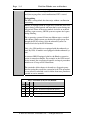
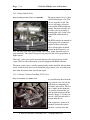
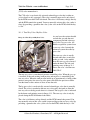
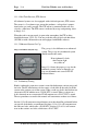
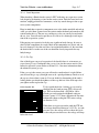
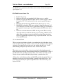
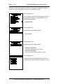
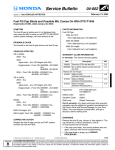
Module 33
Evaporative Monitor
Author: Grant Swaim
E-mail: [email protected]
URL: www.tech2tech.net
Phone: (336) 632-9882
Fax: (336) 632-9688
IMPORTANT - READ !
Do not read or study this information unless you agree to the
following conditions:
The information in this training module is the intellectual
property of Grant Swaim and is copyrighted by Sure Seal
Products Inc.
As a subscriber to the Tech-2-Tech website, or the on-line
training
Postal Address: Tech-2-Tech Website
PO Box 18443
Greensboro, NC 27419
Physical Address: 220-4 Swing Rd
Greensboro, NC 27409
Last Update: October 2000
Tech-2-Tech offers the following training modules in printed manual, CD-ROM, and on-line formats.
PGMFI Training Modules
•
•
•
•
•
•
•
•
•
•
•
•
•
•
•
•
•
•
•
•
•
•
•
The PGMFI System Overview—Part 1
The PGMFI System Overview—Part 2
PGMFI Flash Type DTCs
Inputs / Outputs—Part 1
Inputs / Outputs—Part 2
Engine Control Module
Air Flow / MAP Sensor—Base Inj Pulse Width
Fuel Delivery System
Closed Loop Strategies—Theory
Closed Loop Strategies—Case Studies
Thermistor Inputs
Throttle Position Sensor
EGR Valve Lift Sensor
MAP / BARO Sensor
Ignition Inputs
Vehicle Speed Sensor
Oxygen Sensor
Lean Air Fuel Sensor
Miscellaneous Input Signals
Fuel Injectors—Multi-Port Injection
Fuel Injectors—Dual Point Injection
Ignition System—Outputs
Idle Air Control Valve
OBD-II Training Modules
•
•
•
•
•
•
•
•
•
•
•
•
•
•
•
On Board Diagnostics—General Overview
Diagnostic Trouble Codes
MIL / Freeze Frame
Scan Tool
Scan Tool—Advanced
Monitor Tests—Overview
Comprehensive Component Monitor
Catalyst Monitor
EGR Monitor
Evaporative Monitor
Fuel System Monitor
Misfire Monitor
Oxygen Sensor Monitor
Oxygen Sensor Heater Monitor
“P” Codes
Miscellaneous Training Material
•
Glossary of Terms
2000 © - All Rights Reserved Sure Seal Products Inc - Greensboro, NC
Visit Our Website: www.tech2tech.net
Page 33-1
33 Evaporative Monitor
Run:
Once-Per-Trip
Enable Criteria:
1. Using an OBD-II compatible scan tool monitor the ECT
and IAT parameters.
2. The car must be started with an ECT and IAT sensor reading of at least 32o F, but not over 95o F.
3. The ECT and IAT sensors must be within 5o F of each
other.
4. Fuel tank must not be over 85% full or below 15% full.
5. Monitor the bypass valve* for activation, to be assured the
EVAP monitor has begun to run, by either:
a. Watching for the sensor’s ground activation
b. Watching for the sensor’s “ON” status with a
Mastertech scan tool equipped with the Honda
software.
6. Start the car
7. If the bypass is activated at start-up, go to step 10. If the
bypass valve is not activated** within 3 seconds, cut the
car off.
8. Restart the car.
9. If the bypass valve is not activated** within 3 seconds cut
the car off. The monitor is not going to run under the current conditions.
10. Test drive the car as close to a steady road speed as possible.
11. The EVAP monitor should run within approximately 5
miles.
* You can find more information about the location and operation
of the bypass valve in Section 33.1.3.
** In most cases the bypass valve will activate on and stay on for
a long period. In some cases the bypass valve is only activated for
approximately 3 seconds. Either one of these situations is an indication that the EVAP monitor is running.
DTC A diagnostic trouble codes (DTC) generated from this monitor is
stored on the second malfunction (first malfunction on a purge
flow switch) during a consecutive running of the monitor.
All DTCs set from this monitor are standard priority within the
freeze frame writing strategy. A freeze frame written by one of
these DTCs can only be over written by a high priority DTC, not
another standard priority DTC.
MIL Info
Illumination
© Sure Seal Products, Greensboro, NC – All Rights Reserved
Page
33-2
Visit Our Website: www.tech2tech.net
The malfunction indicator light (MIL) is illuminated when a second (first on purge flow switch malfunction) DTC is stored.
Extinguishing
The MIL is extinguished after three trips without a malfunction
reoccurring.
General Info: Hondas are equipped with an evaporative system that stores fuel
vapors during parked periods and burns those vapors during running periods. Some of the newer models also have an on-board
refueling vapor recovery (ORVR) system to capture fuel vapors
during refueling.
The evaporative systems fall into two different types, standard
and enhanced. Both systems are checked for proper purge flow
through the EVAP canister. Only the enhanced systems are
checked for leaks by the EVAP monitor.
Only a few 1996 models were equipped with the enhanced systems. By 1998, all models were equipped with the enhanced system.
As on most OBD-II equipped vehicles, the Honda evaporative
system is somewhat complex. For example, in the 1998 Accord
service manual, the evaporative diagnostic and repair procedures
include over 85 steps and 30 illustrations.
The remainder of this chapter is devoted to a diagnostic procedure for testing the evaporative system for leaks. This procedure
is very effective and much easier to follow than most procedures
covered in service manuals.
DTCs Generated by the EVAP Monitor
OBD MIL Trips
Code Flash
Description
P0441
92
2
EVAP – Insufficient Purge Flow
P1456
90
2
EVAP – Leak Detected (Fuel Tank System)
P1457
90
2
EVAP – Leak Detected (Control Canister System)
P1459
92
1
EVAP – Purge Flow Switch Malfunction
© Sure Seal Products, Greensboro, NC – All Rights Reserved
Visit Our Website: www.tech2tech.net
Page 33-3
33.1 Evaporative System – General Overview
Honda uses two different evaporative systems; the standard system that checks for
canister purge flow only and the enhanced systems that add leak detection. Enhanced systems are found on a few 1996 models, and were added to all systems
by 1998. This training module concentrates on the enhanced systems.
The enhanced systems are composed of these main components:
This solenoid type valve is duty cycled by the ECM to obA Purge Control
Valve
tain proper canister purge
The valve is normally open and is only commanded shut
B Canister Vent
Shut (CVS)
by the ECM when it is leak checking the evaporative sysValve
tem
The canister stores the gas tank emissions during parked
C Canister
periods. The canister is purged during driving periods
D Two-Way Valve This mechanical valve allows the gas tank to vent when
the pressure exceeds approx .6 inHg, either positive or
negative.
During a leak check the ECM activates the bypass valve,
E Bypass Valve
which bypasses the two-way valve.
F Fuel Tank Pres- A 5v reference type sensor that produces a voltage proporsure (FTP) Sen- tional to tank pressure. A tank with no pressure produces a
sor
FTP sensor voltage of 2.45-2.55v.
The gas tank filler cap for an enhanced evaporative system
G Gas Tank With
Special Filler
is specially designed.
Cap
© Sure Seal Products, Greensboro, NC – All Rights Reserved
Page
33-4
Visit Our Website: www.tech2tech.net
33.1.1 Purge Control Valve
Image 33-1 Purge Control Valve on a 2000 CRV
The purge control valve is a duty
cycled solenoid type valve. The
valve is normally closed. The
valve is fed battery voltage directly and the ECM controls the
ground. You may manually activate this valve by providing a
ground to the valve (at the valve
or the ECM) while the key is
“On”.
The ECM controls the amount of
air that purges the evaporative
canister by duty cycling this
valve, which applies manifold
vacuum to the evaporative system. The duty cycle of the purge control valve varies widely based on many engine conditions. The canister is typically not purged at idle and is purged more at
higher speeds.
The valve’s duty cycle can be measured directly with a digital storage oscilloscope (DSO) or with a Mastertech scan tool equipped with Honda software.
The purge control valve is usually mounted on the intake manifold, the left shock
tower, or the firewall. One way to identify the purge control valve is to follow the
hose from the canister back towards the engine.
33.1.2 Canister / Canister Vent Shut (CVS) Valve
Image 33-2 Canister on a 2000 Accord
As you follow the hose from the
purge control valve towards the
tank, the next component you
will find is the canister. The canister is either located under the
car (usually in front of the gas
tank) or under the hood (on the
firewall). Image 33-2 is the canister on a 2000 Accord and it is
located under the car.
If the evaporative system is an
enhanced version the canister
will have a canister vent shut
© Sure Seal Products, Greensboro, NC – All Rights Reserved
Visit Our Website: www.tech2tech.net
Page 33-5
(CVS) valve mounted on it.
The CVS valve is an electrically activated solenoid type valve that is either on
(valve closed) or off (vent open). The valve is normally open and is only closed
by the ECM to run the EVAP leak check. The valve is fed battery voltage directly
and the ECM controls the ground. You may manually activate this valve (make it
close) by providing a ground to the valve (at the valve or the ECM) while the key
is “On”.
33.1.3 Two-Way Valve / By-Pass Valve
Image 33-3 Two-Way and By-Pass Valve
As you leave the canister headed
towards the gas tank the next
component you find is the twoway valve / by-pass valve. All
Honda evaporative systems have
a two-way valve, but only the
enhanced systems have the bypass valve.
The two-way valve is usually
located under the car and close
to the gas tank. A few models
have the two-way valve located
under the hood. The left ward
pointing arrow in Image 33-3
shows the valve’s location on a
2000 CR-V.
The two-way valve is a mechanical pressure controlling valve. When the gas cap
is installed all the tank venting, both positive and negative, is controlled by the
two-way valve. When the tank pressure builds up to approximately .6 inHg (either
positive or negative) the two-way valve opens and allows the pressure to either
vent the fumes to the canister or draw air into the tank.
The by-pass valve is an electrically actuated solenoid type valve that is normally
closed. The valve is attached to the two-way valve and is designed to allow the
two-way valve to be by-passed when it is actuated. The by-pass valve is indicated
by the down ward pointing arrow in Image 33-3. The two-way valve is only bypassed during the EVAP monitor leak checks.
The valve is fed battery voltage directly and the ECM controls the ground. You
may manually activate this valve (make it open and bypass the two-way valve) by
providing a ground to the valve (at the valve or the ECM) while the key is “On”.
© Sure Seal Products, Greensboro, NC – All Rights Reserved
Page
33-6
Visit Our Website: www.tech2tech.net
33.1.4 Fuel Tank Pressure (FTP) Sensor
All enhanced systems are also equipped with a fuel tank pressure (FTP) sensor.
The sensor is a 5v reference type sensor that produces a voltage that is proportional to the gas tank’s pressure. The FTP sensor is connected to the two-way
valve by a short hose. The FTP sensor is indicated by an up ward pointing arrow
in Image 33-3.
When the tank is not pressured (is open to the atmosphere) the FTP reading
should be between 2.45-2.55v. You may read this with a digital volt ohm meter
(DVOM) or with a Mastertech scan tool equipped with Honda software.
33.1.5 Enhanced System Gas Cap
Image 33-4 Enhanced System Cap
The gas cap is also different on an enhanced
system. The gas cap on an enhanced system
should contains the words:
“If not tightened 3 clicks
check engine light
may come on”
Image 33-4 shows the proper gas cap for the
enhanced systems. Loose or improper gas
caps are the number one cause of EVAP
monitor failures.
33.2 Preliminary Testing
Honda’s enhanced evaporative system is tested for both proper canister purge and
for leaks. The EVAP monitor can also narrow a leak down to the tank part of the
system or the canister part of the system. When a tank area leak is detected on two
consecutive EVAP monitor tests a P1456 DTC is stored. When a canister area
leak is detected on two consecutive EVAP monitor tests a P1457 DTC is stored.
The test procedures covered in this manual will concentrate on these two failures.
Section 33.2 will concentrate on preliminary tests that should be performed before
any specific leak checks are performed. Sections 33.3 & 33.4 will concentrate on
the tank area leaks, which store a P1456 DTC. Section 33.5 & 33.6 will concentrate on the canister area leaks, which store a P1457 DTC.
© Sure Seal Products, Greensboro, NC – All Rights Reserved
Visit Our Website: www.tech2tech.net
Page 33-7
33.2.1 Visual Inspection
When checking a Honda that has stored a DTC indicating an evaporative system
leak, begin by performing a visual on the entire system. Look for loose hose connections, unplugged electrical connectors, or for any wreck damage to the evaporative system components.
Keep in mind that evaporative components start at the intake manifold and end up
at the gas tank. Some systems have the canister under the hood and some have the
canister under the car. The two-way and bypass valves are usually located under
the car, also. You will need to put the car on a lift to do a thorough visual inspection of the evaporative system.
If diagnosing an evaporative leak after any significant body damage, be sure to
check all the components for cracks. Most of the components are plastic and can
be easily damaged. Also the steel lines, located underneath the car, that run from
the front of the car to the rear of the car should be closely inspected after any
body damage,
33.2.2 Gas Cap
One of the biggest causes of evaporative leak check failures is an incorrect gas
cap or loose gas cap. Confirm that the gas cap is in fact the correct one for an enhanced evaporative system. Refer to Section 33.1.5 for more information about
the enhanced system gas cap.
If the gas cap is the correct part, you will need to confirm that it is tight. Before
you twist on the gas cap, you might want to do a quick preliminary check to see if
the cap was loose when it came in. You can do this by determining if the tank is
leaking before you check the tightness of the cap, then see if the leak stops after
you tighten and/or replace the cap.
Screen Capture 33-1
To do a quick check for a leaking gas cap start by
checking the fuel tank pressure (FTP) sensor voltage. This can be done with a DVOM or a Mastertech scan tool equipped with Honda software.
Screen Capture 33-1 is from a Mastertech. For more
information about reading the FTP sensor voltage
see Section 33.2.3.
When there is no pressure on the tank, the FTP sensor voltage should read between 2.45-2.55v. As tank
pressure rises, the voltage will rise above this level.
As the tank pressure decreases, the voltage will drop
below this level.
© Sure Seal Products, Greensboro, NC – All Rights Reserved
Page
33-8
Visit Our Website: www.tech2tech.net
With the ever changing temperature of the fuel in the gas tank, it is rare that the
FTP sensor reads 2.5v. For instance, if a car has sat outside and has cooled overnight, it is normal for the FTP sensor voltage to be under 2.5v. If a car is sitting
outside during the day where the temperature has risen significantly it is normal to
see a FTP sensor reading over 2.5v.
Due to the fuel being constantly pumped to the fuel rail and returned to the tank
(except for return less systems on some 2001 models), the fuel in the tank will
usually rise at least 300F on a running Honda. This means that a running Honda
will almost always have a rising FTP sensor voltage. If the ambient temperature is
extremely cold or falling, this may not be the case.
With this in mind, before disturbing the gas cap, check the FTP sensor voltage. If
the reading is 2.5v, yet conditions exist that would normally created a high or low
tank pressure, then there probably is a leak. Then tighten the cap to see if the tank
pressure changes over the next 15-20 minutes. If it does the gas cap was not tight
enough. If tightening the cap did not make a difference, try a known good gap and
see if the tanks pressure changes. If so the original cap is bad.
The best way to create a situation where the fuel tank pressure should be changing
is to heat up the fuel in the tank, by running the engine, which will cause a pressure rise. A Honda running, at least 20 minutes, should have a rising FTP sensor
voltage. On a hot day the FTP sensor voltage will quickly reach the maximum of
about 3.1v. The two-way valve will bleed off any pressure above this.
33.2.3 Check FTP sensor
Image 33-5
Since almost all evaporative leak
checks revolve around the FTP
sensor output, you need to start
by checking it first. The FTP
sensor has three wires, and is a
5-volt reference type sensor. The
ECM supplies a reference voltage (5v) and a ground to the sensor over two of the wires. The
FTP sensor returns back an analog voltage to the ECM over the
third wire. While this is a listed
parameter on a Mastertech scan
tool equipped with Honda soft
ware, you can also get this voltage using a standard DVOM.
Image 33-5 shows the FTP sensor on a 2000 CRV. Note the 3-wire connector. If
checking the FPT sensor voltage using a DVOM, simply back probe this connector until you find the input wire. Remember one wire should have approx 5v on it,
© Sure Seal Products, Greensboro, NC – All Rights Reserved
Visit Our Website: www.tech2tech.net
Page 33-9
one should have a ground (less than 50mv) on it and one will have the input voltage of approx 2.5v.
Fuel Tank Pressure Sensor Test
1. Remove the gas cap
2. Make sure the tank is not completely full, drain out gas as needed.
3. With key on engine off (KOEO) Check the FTP sensor voltage. It should
be between 2.45-2.55v and steady. If so the sensor is good. If not go to
step 4.
4. Disconnect the hose between the FTP sensor and the two-way valve.
5. With KOEO, recheck the FTP sensor voltage. It should be between 2.452.55v and steady. If so the sensor is good, however there is a restriction in
the evaporative system, go to step 5. If not replace the FTP sensor and retest.
6. Look for a restriction between the FTP and the gas tank. This is usually
caused by a defective onboard refueling vapor recycling (ORVR) system,
which allows gasoline to enter the evaporative system. If gas is present,
replace all components exposed to the gas, replace the ORVR valve, and
re-test the FTP sensor.
33.2.4 Solenoid Check
The last step in the preliminary checks is to confirm that each of the three electrically activated valves (purge control, canister vent shut, and bypass) do respond to
activation. You should activate each valve and confirm that the valve “clicks”
whole holding it. Replace any defective valves and retest the system.
The easiest way to activate these valves is to use the bi-directional commands
from a Mastertech scan tool using the Honda Software Version SN010, or later. If
you do not have the capability to activate these valves with a scan tool, you can
always activate each one individually by providing a ground to the valve.
All the valves are fed battery voltage and the ECM provides the ground. You can
manually activate each valve by providing a ground at each of the valves. You
will need to first identify the power and ground wire on the sensor using a test
light or DVOM.
© Sure Seal Products, Greensboro, NC – All Rights Reserved
Page
33-10
Visit Our Website: www.tech2tech.net
Following is the menu sequence to follow to activate the solenoids with a Mastertech scan tool using Honda software Version SN010 or later.
Screen Capture 33-2
This is the main menu of a Mastertech scan tool using the Honda software Version SN010 or later.
From this menu choose:
6: INSPECTION
Screen Capture 33-3
From the Inspection Menu choose:
2. EVAP TEST
Screen Capture 33-4
From the Evap Test Menu choose:
1: SINGLE SOLENOID
To activate the valves one at a time
2: MULTI SOLENOIDS
To activate more than one valve at a time
Screen Capture 33-5
From the Single Solenoid Menu you can activate
and deactivate each of the three evaporative valves.
© Sure Seal Products, Greensboro, NC – All Rights Reserved
Visit Our Website: www.tech2tech.net
Page 33-11
Screen Capture 33-6
From the Multi Solenoids Menu you can activate
more than one of the evaporative valves in different
combinations.
© Sure Seal Products, Greensboro, NC – All Rights Reserved
Page
33-12
Visit Our Website: www.tech2tech.net
33.3 P1456 Test Procedure – For Under Hood Canister Models
Use this diagnostic procedure if you have a stored P1456 DTC. This is an indication that you have a leak in the tank area of the system. This procedure is for
models with the canister mounted under the hood. For models with the canister
mounted under the car see Section 33.4.
1.
2.
3.
4
5.
6.
The gas tank should be at
least ½ full but not completely full.
Make sure the proper cap
is in place and tight
Activate the Bypass Valve
Disconnect the hose between the two-way valve
and canister at the canister.
This hose is usually labeled “Tank” on the canister. Connect a vacuum
pump to the hose.
See Section 33.2.4
Image 33-6
Apply vacuum until the
FTP sensor reads 1.49v. As
soon as the voltage rises to
1.5v start timing a 20 second period. If the voltage
rises above 1.55v in 20
seconds the leak check has
failed
If the system passed the
leak check there is no
problem. If it failed the
leak check, go to step 7.
© Sure Seal Products, Greensboro, NC – All Rights Reserved
Visit Our Website: www.tech2tech.net
7.
Leave the vacuum pump
attached, but pinch off the
hose between the two-way
valve and the gas tank.
Page 33-13
Image 33-7
Note that on most models
the two-way valve is under
the car and close to the gas
tank, such as shown in Image 33-7.
On a few models this valve
is located under the hood.
8.
9.
Re-run the leak check described in Step 5.
If the system passes the
test, there is a leak in the
tank area.
If the system fails the test
there is a leak in the twoway/bypass valve area
10. Diagnose leak, repair, and
retest the system.
© Sure Seal Products, Greensboro, NC – All Rights Reserved
Page
33-14
Visit Our Website: www.tech2tech.net
33.4 P1456 Test Procedure – For Under Car Canister Models
Use this diagnostic procedure if you have a stored P1456 DTC. This is an indication that you have a leak in the tank area of the system. This procedure is for
models with the canister mounted under the car. For models with the canister
mounted under the hood, see Section 33.3.
1.
2.
3.
4
5.
6.
The gas tank should be at
least ½ full but not completely full.
Make sure the proper cap
is in place and tight
Activate the Bypass Valve
Disconnect the hose between the two-way valve
and canister at the canister.
This hose is usually labeled “Tank” on the canister. Connect a vacuum
pump to the hose.
See Section 33.2.4
Image 33-8
Apply vacuum until the
FTP sensor reads 1.49v. As
soon as the voltage rises to
1.5v start timing a 20 second period. If the voltage
rises above 1.55v in 20
seconds the leak check has
failed
If the system passed the
leak check there is no
problem. If it failed the
leak check, go to step 7.
© Sure Seal Products, Greensboro, NC – All Rights Reserved
Visit Our Website: www.tech2tech.net
7.
If the car is equipped with
an ORVR system follow
this step, if not skip to step
10.
Page 33-15
Image 33-9
If the car is equipped with
the ORVR system it will
have an third hose attached
to the canister. The hose is
large in size and is attached
to the canister with a
“quick disconnect” type
fitting.
8.
9.
Disconnect the ORVR
hose from the canister and
plug the hose
Re-run the leak check described in Step 5.
If the system passes the
test, replace the ORVR
valve.
If the system fails the test,
reconnect the ORVR hose
and proceed to step 10.
10. Leave the vacuum pump
attached, but pinch off the
hose between the two-way
valve and the gas tank.
Image 33-10
11. Re-run the leak check described in Step 5.
© Sure Seal Products, Greensboro, NC – All Rights Reserved
Page
33-16
Visit Our Website: www.tech2tech.net
12. If the system passes the
test, there is a leak in the
tank area.
If the system fails the test
there is a leak in the twoway/bypass valve area
13. Diagnose leak, repair, and
retest the system.
© Sure Seal Products, Greensboro, NC – All Rights Reserved
Visit Our Website: www.tech2tech.net
Page 33-17
33.5 P1457 Test Procedure – For Under Hood Canister Models
1.
Isolate the fuel tank from
the system by clamping off
the hose that goes from the
two-way valve to the fuel
tank.
Image 33-11
Note that on most models
the two-way valve is under
the car and close to the gas
tank, such as shown in Image 33-11.
On a few models this valve
is located under the hood.
2.
3.
4.
Activate the purge control
valve, canister vent shut
valve, and bypass valve
either manually or by using
the Mastertech scan tool.
See Section 33.2.4
Image 33-12
Disconnect the hose between the intake manifold
and the purge control valve
at the manifold. Attach a
vacuum pump to this hose.
Apply vacuum until the
FTP sensor reads 1.49v.
Then disconnect the purge
control valve and vent the
vacuum pump.
© Sure Seal Products, Greensboro, NC – All Rights Reserved
Page
5.
6.
7.
8.
9.
33-18
Visit Our Website: www.tech2tech.net
As soon as the voltage
rises to 1.5v start timing a
20 second period. If the
voltage rises above 1.55v
in 20 seconds the leak
check has failed
If the system passes this
leak check there is no
problem.
If the system failed this
leak test go to step 7.
Disconnect the hose from
the purge control valve to
the canister from the purge
control valve. Attach a
vacuum pump to this hose.
Image 33-13
Apply vacuum until the
FTP sensor reads 1.49v. As
soon as the voltage rises to
1.5v start timing a 20 second period. If the voltage
rises above 1.55v in 20
seconds the leak check has
failed.
If the system passes this
leak check, the purge control valve is leaking, replace the valve and retest.
If the system fails the test,
go to step 10.
© Sure Seal Products, Greensboro, NC – All Rights Reserved
Visit Our Website: www.tech2tech.net
10. With the vacuum pump
still attached pinch off the
canister vent shut valve
hose
Page 33-19
Image 33-14
11. Re-test for a leak using the
test from step 8.
12. If the system passes this
leak check, the canister
vent shut valve is leaking,
replace the valve and retest.
If the system fails the test,
go to step 13.
Image 33-15
13. Disconnect the hose from
the canister and two-way
valve at the canister; this is
often labeled at the canister
as “Tank”.
Attach a vacuum pump to
this hose.
© Sure Seal Products, Greensboro, NC – All Rights Reserved
Page
33-20
Visit Our Website: www.tech2tech.net
14. Re-test for a leak using the
test from step 8.
15. If the system passes this
leak check, the canister is
leaking, replace the canister and retest the system.
If the system fails the test,
there is a leak in the twoway valve / bypass valve
area. Diagnose, repair and
retest the system.
© Sure Seal Products, Greensboro, NC – All Rights Reserved
Visit Our Website: www.tech2tech.net
Page 33-21
33.6 P1457 Test Procedure – For Under Car Canister Models
Image 33-16
1.
Isolate the fuel tank from
the system by clamping off
the hose that goes from the
two-way valve to the fuel
tank.
2.
Activate the purge control
valve, canister vent shut
valve, and bypass valve
either manually or by using
the Mastertech scan tool.
See Section 33.2.4
Image 33-17
Disconnect the hose between the intake manifold
and the purge control valve
at the manifold. Attach a
vacuum pump to this hose.
3.
4.
Apply vacuum until the
FTP sensor reads 1.49v.
Then disconnect the purge
control valve and vent the
vacuum pump.
© Sure Seal Products, Greensboro, NC – All Rights Reserved
Page
5.
6.
7.
8.
9.
33-22
Visit Our Website: www.tech2tech.net
As soon as the voltage
rises to 1.5v start timing a
20 second period. If the
voltage rises above 1.55v
in 20 seconds the leak
check has failed
If the system passes this
leak check there is no
problem.
If the system failed this
leak test go to step 7.
Disconnect the hose from
the purge control valve to
the canister from the purge
control valve. Attach a
vacuum pump to this hose.
Image 33-18
Apply vacuum until the
FTP sensor reads 1.49v. As
soon as the voltage rises to
1.5v start timing a 20 second period. If the voltage
rises above 1.55v in 20
seconds the leak check has
failed.
If the system passes this
leak check, the purge control valve is leaking, replace the valve and retest.
If the system fails the test,
go to step 10.
© Sure Seal Products, Greensboro, NC – All Rights Reserved
Visit Our Website: www.tech2tech.net
10. With the vacuum pump
still attached pinch off the
canister vent shut valve
hose
Page 33-23
Image 33-19
11. Re-test for a leak using the
test from step 8.
12. If the system passes this
leak check, the canister
vent shut valve is leaking,
replace the valve and retest.
If the system fails the test,
go to step 13.
13. If the Honda is equipped
with the ORVR system
follow this step, if not
jump to step 16.
Image 33-20
If the car is equipped with
the ORVR system the canister will have a third hose.
The hose is large and is
attached to the canister by
a quick-disconnect type
fitting.
Disconnect the ORVR vent
hose and plug the canister.
14. Re-test for a leak using the
test from step 8.
© Sure Seal Products, Greensboro, NC – All Rights Reserved
Page
33-24
Visit Our Website: www.tech2tech.net
15. If the system passes this
leak check, the ORVR
valve is leaking, replace
the valve and retest.
If the system fails the test,
go to step 16.
Image 33-21
16. Disconnect the hose from
the canister and two-way
valve at the canister; this is
often labeled at the canister
as “Tank”.
Attach a vacuum pump to
this hose.
17. Re-test for a leak using the
test from step 8.
18. If the system passes this
leak check, the canister is
leaking, replace the canister and retest the system.
If the system fails the test,
there is a leak in the twoway valve / bypass valve
area. Diagnose, repair and
retest the system.
© Sure Seal Products, Greensboro, NC – All Rights Reserved