1
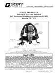
Module 20 Fuel Injectors - Multi-Port Injection (MPI) Author: Grant Swaim E-mail: [email protected] URL: www.tech2tech.net Phone: (336) 632-9882 Fax: (336) 632-9688 Postal Address: Tech-2-Tech Website PO Box 18443 Greensboro, NC 27419 Physical Address: 220-4 Swing Rd Greensboro, NC 27409 Last Update: April 2000 IMPORTANT - READ ! Do not read or study this information unless you agree to the following conditions: The information in this training module is the intellectual property of N. Grant Swaim and is copyrighted by Sure Seal Products Inc. Subscribers to the Tech-2-Tech website, and persons participating in Tech-2-Tech’s on-line training program are entitled to read this material on-line. You may also click on the “save” icon on the Acrobat viewer and save a copy to your local computer. You may save a copy of this file on one computer and it must be viewed from that one computer. You may also print one copy of this file for your viewing. If the printed copy becomes illegible, or lost, an additional copy may be printed. Tech-2-Tech offers the following training modules in printed manual, CD-ROM, and on-line formats. PGMFI Training Modules • • • • • • • • • • • • • • • • • • • • • • • The PGMFI System Overview—Part 1 The PGMFI System Overview—Part 2 PGMFI Flash Type DTCs Inputs / Outputs—Part 1 Inputs / Outputs—Part 2 Engine Control Module Air Flow / MAP Sensor—Base Inj Pulse Width Fuel Delivery System Closed Loop Strategies—Theory Closed Loop Strategies—Case Studies Thermistor Inputs Throttle Position Sensor EGR Valve Lift Sensor MAP / BARO Sensor Ignition Inputs Vehicle Speed Sensor Oxygen Sensor Lean Air Fuel Sensor Miscellaneous Input Signals Fuel Injectors—Multi-Port Injection Fuel Injectors—Dual Point Injection Ignition System—Outputs Idle Air Control Valve OBD-II Training Modules • • • • • • • • • • • • • • • On Board Diagnostics—General Overview Diagnostic Trouble Codes MIL / Freeze Frame Scan Tool Scan Tool—Advanced Monitor Tests—Overview Comprehensive Component Monitor Catalyst Monitor EGR Monitor Evaporative Monitor Fuel System Monitor Misfire Monitor Oxygen Sensor Monitor Oxygen Sensor Heater Monitor “P” Codes Miscellaneous Training Material • Glossary of Terms 2000 © - All Rights Reserved Sure Seal Products Inc - Greensboro, NC Page 20-1 Visit Our Website: www.tech2tech.net 20 Fuel Injectors - Multi-Port Injection 20.1 General Overview The fuel injector is a solenoid style output device that directly controls fuel delivery into the intake manifold. The injectors are operated by a duty cycle type signal from the engine control module (ECM). The amount of fuel delivered is directly proportionate to how long the ECM keeps the injector open. Image 20-1 The PGMFI system can be a multi-port injection (MPI) system or a dual-point injection (DPI) system. The MPI system is by far the more popular of the two systems. This module covers the MPI system only! Chapter 21 "Injectors Dual Point Injection" covers the DPI system. The bottom fuel injector in Image 20-1 is a MPI injector. The top two injectors are DPI injectors. Virtually all MPI injectors look identical and have the same external dimensions. The o-ring (on the inlet of the injector) should be replaced anytime the injector is removed and reinstalled. 20.2 How Do They Work? Illustration 20-1 Typical Fuel Injection Schematics As can be seen in Illustration 20-1, the injector circuit is supplied battery voltage from the main relay. The main relay will supply power to the circuit for 2 seconds after the key is first turned on, then only if the engine is running. Most of the MPI systems used an external resistor pack as shown in the drawing. The newer model Hondas have dropped the external resistor packs and All Rights Reserved 2000 Sure Seal Products Inc This manual printed 4/9/00 from the file pgmfiobd_002. Page 20-2 Visit Our Website: www.tech2tech.net have added the resistance to the injector itself. All external resistance packs added 5-7 ohms to each of the injector circuits. The injector windings are the next item in the injector circuit. The injector windings will either be 1.2-2.5 ohms (with external resistor pack) or 10-13 ohms (with internal resistor). It is not common for an injector winding to fail or short. The added resistance in the injector circuits is for current control. Full battery voltage is applied across the injector initially to get the pintle to open quickly. After the current starts to flow the added resistance in the circuit will drop the current back to a lower level. Once the pintle is open it does not require much current to keep the pintle open. The injector windings are grounded by driver transistors in the ECM. When the processor of the ECM commands the injector on, a signal is sent to the injector driver and the transistor grounds the injector until the processor stops commanding the injector on. Since the ECM is controlling the ground, if the wire from the injector to the ECM were to become grounded, the ECM would not be harmed. 20.3 Fuel Delivery Strategies The fuel injector is the output device that is responsible for directly controlling fuel delivery. The fuel pump and regulator supply the inlet of the injector with a constant regulated supply of fuel. The fuel is even adjusted for changes in the manifold pressure, so that the pressure differential between the fuel supply and the intake manifold is always constant. The amount of fuel injected is directly proportional to the amount of time the fuel injector is turned on. The injector "on time" is typically referred to as pulse width (PW) and is measured in milliseconds (ms). The unit of measure for injector operation should always be time, not a duty cycle or dwell unit. When injector operation is measured as a duty cycle, the value becomes RPM dependant. The injector's PW will vary depending on many inputs. The ECM turns the injector on the correct amount of time to deliver the optimum amount of fuel for the given conditions. In addition to delivering the correct amounts of fuel, there are two occasions when the injectors are turned off totally. This happens at a preprogrammed high rpm, and during deceleration periods. The typical PW of a MPI system at idle with no load is 1.75-2.75ms. All Rights Reserved 2000 Sure Seal Products Inc This manual printed 4/9/00 from the file pgmfiobd_002. Page 20-3 Visit Our Website: www.tech2tech.net Image 20-2 The PGMFI MPI System 20.4 Component Location Multi Port System The MPI system was by far the most popular system used. The MPI has an injector for each cylinder. The injectors can be easily seen from the top (shown at arrow in Image 20-2). MFI systems have been used on: 85-98 Accords / 95-98 Odysseys / 85-98 Civics / 85-98 Preludes 20.5 How Do You Test Them? Just like most other Honda fuel infection components, the fuel injectors are fairly fool proof. An electrical failure is very uncommon. The two more common problems that you might experience with a Honda are poor spray patterns and leaking injector bodies. These two issues are covered in detail in the "Service Tips" section at the end of this module. As far as testing the injectors (on the car) you have three choices, checking the injector's PW, the injector's winding resistance, and monitoring the injector’s current. Screen Capture 20-1 20.5.1 Injector Pulse Width You can actually measure voltage at the ground side of the injector and determine the injector's PW. While this is a very useful test for diagnosing fuel delivery problems, it is not real effective in finding injectors with stuck pintles. The best way to confirm an injector's pintle is opening and All Rights Reserved 2000 Sure Seal Products Inc This manual printed 4/9/00 from the file pgmfiobd_002. Page 20-4 Visit Our Website: www.tech2tech.net closing is to monitor the injector’s current with a DSO. The PW can be measured with a digital storage oscilloscope (DSO) as shown on Screen Capture 20-1, on the left. Battery voltage is present on the ground side of the injector when it is turned off since there is no ground and subsequently no current is flowing in the injector circuit. When the injector is turned on, the voltage is pulled close to 0 volts, as the driver transistor provides a ground. The length of time the pintle is held open by the continued current in the injector winding can be measured by looking at the bottom time line. The time between the injector on time and the injector off time is the PW. The injector off time is indicated by the voltage returning to battery voltage. When the ground is released there is an inductive spike produced by the collapsing electromagnetic field, this is normal. The PW of the screen capture in Figure 4, is 2.75ms. You can see that the time division is set up for 1ms per division. The injector is grounded for 2.75 divisions. 20.5.2 Injector Resistance Injector Resistance Values in Ohms Model Injector Resistor Year Ohms Ohms Accord 85-97 1.5-2.5 5-7 98 10-13 N/A Civic MPI 85-91 1.5-2.5 5-7 92-98 10-13 N/A Odyssey 95-97 1.5-2.5 5-7 98 10-13 N/A Prelude The only injector test that is covered in the Honda service manual is an injector resistance test. The resistance information was also dropped from the later model manuals. Based on field observations, I was able to complete this information up thru 1998. All MPI injectors with an external resistance pack will measure 1.5 - 2.5 ohms across its winding. There should be no continuity from the winding to the injector body All external injector resistor packs are 5-7 ohms All MPI injectors with an internal resistor measure 10-13 ohms across its winding. There should be no continuity from the winding to the injector body. 85-96 1.5-2.5 5-7 97-98 10-13 N/A All Rights Reserved 2000 Sure Seal Products Inc This manual printed 4/9/00 from the file pgmfiobd_002. Page 20-5 Visit Our Website: www.tech2tech.net 20.5.3 Fuel Injector Current Waveforms The test that gives you the most information about the operation and condition of a fuel injector is the current test. Just within the last few years current probes have become commercially available that will allow a tech to observe the current flow in small time units. Current probes are presently available for under $300 that will measure current accurately in time units as small as 1ms. Screen Capture 20-2 D C B A Screen Capture 20-2 shows the current waveform of a Honda fuel injector. When monitoring the ground control (such as in Screen Capture 201) the tech only knows that the injector was grounded and for how long. By monitoring the current flow during this event, much more can be learned. Point A At point A the injector is grounded and current starts to flow. Note that the current does not instantly reach maximum current flow. The current climbs to the maximum flow over a period of about 1.5ms. The reason for this climb in current (often called a current ramp) is that a winding of wire will have a resistance to current rise that is in addition to the resistive value of the circuit. This natural resistance a coil of wire adds is called inductive reactance. By point C, the inductive reactance is no longer affecting the current and the current is being controlled by the resistance of the circuit. The characteristics of this current ramp are directly controlled by the characteristics of the coil in the circuit. The slope, change of slope, and other characteristics of the ramp can give an indication of the condition of the coil in the circuit. In general when a coil has shorted windings the ramp will climb much faster and take on a “bowed out” appearance. This would be an indication of a failing injector. Point B Since the ramp is controlled by the characteristics of the coil in the circuit, something must have changed to the characteristics of the coil at point B. The change was that the pintle moved. When the metal pintle moves inside the injectors winding it changes the inductive reactance of the injector’s winding. This subtle change in the injector’s inductive reactance causes this change in the current ramp and is often called a pintle bump/hump. All Rights Reserved 2000 Sure Seal Products Inc This manual printed 4/9/00 from the file pgmfiobd_002. Page 20-6 Visit Our Website: www.tech2tech.net So by checking the injector’s current we can actually tell if and when the pintle opened. You can quickly compare the current on all injectors and confirm that they are all opening at approximately the same point on the current ramp. Point C At point C the current has reached the saturation point of the circuit. The inductive reactance of the winding is no longer affecting the current flow. This maximum current flow is controlled by the resistance of the circuit. Most Honda injectors will flow about 1.5 – 1.8 amps. Screen Capture 20-3 Point D At point D the injector ground is released and the injector current drops to 0 and the injector closes. The time difference between point A and point D is the PW of the injector. You can clamp on each injector circuit individually to observe each injector’s waveform, or clamp on the injector’s feed wire to observe all the injector waveforms at once. Screen Capture 203 shows all the injectors’ current draw shown at once. When comparing the total current draw of all the injectors it is easier to have all the patterns on the screen at once. Image 20-2 When using an amp probe you simply clamp the probe over the wire you want to measure the current in. You can clamp either wire at an injector since it is the same current on either side. On the models with external injector resisters it is best to get the signal at the resistor block. From there you can clamp each individual injector or clamp on the feed wire and see all the injectors at once. This setup is shown in Image 20-2. All Rights Reserved 2000 Sure Seal Products Inc This manual printed 4/9/00 from the file pgmfiobd_002. Visit Our Website: www.tech2tech.net Page 20-7 20.6 Service Issues Honda fuel injectors are reasonably durable. Many Hondas go a lifetime on the original set. There are a few service related situations related to fuel injectors and I have included some of them here. Some are somewhat common and some are rare, but you need to know about them! 20.6.1 Poor Spray Pattern From time to time you may experience a Honda that has a driveability problem, runs poorly when cold, or is failing an emissions test. This could be caused by an injector that has a poor spray pattern. Fuel that is not atomized correctly by the injector is hard to ignite and will not burn completely. A poor spray pattern could be cause by partially clogged or dirty injectors. Poor injector spray patterns typically tend to cause more driveability problems on cold starts. If you suspect a problem with a fuel injector, there is no real easy way to test one other than to replace it with a known good injector. Fortunately, changing injectors on a Honda is very easy (15-20 minutes). If you do not have a spare "test" injector, you can try swapping an injector on a cylinder with a miss to one that does not miss. If the miss moves with the injector, the injector is bad. The only effective way to repair this problem is to replace the injectors, preferably as a set. 20.6.2 Leaking Injectors The biggest problem with Honda injectors is not usually any performance related issue. It is simply a fuel leak in the injector body. The injectors are made in two parts (plastic and steel) and they will sometimes develop a leak where the two parts are crimped together. If the injector is leaking at the crimp, replace it! If the injector is getting wet with fuel on the top half, it could be coming from a leaking injector o-ring. To determine if it is leaking at the top injector o-ring or the injector crimp you will have to dry everything off and watch for the source of the fuel. Many times a tech will replace the top injector o-rings when it is a leaking injector. This just creates a customer comeback and additional work. It is my experience that the upper injector o-rings do not normally start leaking from age. They usually leak whenever the fuel injector was pulled and replaced and new o-rings were not used. If you are getting a fuel leak in the injector area and the injectors have never been pulled, suspect a leaking injector body. All Rights Reserved 2000 Sure Seal Products Inc This manual printed 4/9/00 from the file pgmfiobd_002. Page 20-8 Visit Our Website: www.tech2tech.net 20.6.3 Wrong Injectors Unfortunately, virtually all the Honda MPI injectors have the same external dimensions. It is not uncommon to find a wrong set of injectors in a Honda. Once you have seen this a few times, it is fairly easy to diagnose. Let's take a look at the two scenarios: Injectors Are Too Small If the injectors in an engine were designed for a smaller displacement engine, for a given pulse width the car will be running lean. This is more noticeable in open loop (OL) since the oxygen (O2) sensor feedback cannot help richen the mixture. The typical scenario is the O2 sensor will fix on lean (low volts) since the small injector cannot deliver adequate fuel. This will eventually set a diagnostic trouble code (DTC) 1. When you check a car with a DTC 1, first check to see if the O2 sensor is fixed at a high or low voltage. If the injectors are too small it will be fixed on a low voltage. When you check the injector's PW you will probably find it from normal to wide. The ECM is trying to drive the fuel system richer, but within the window of authority of the O2 sensor. When you see O2 fixed on lean and the PW normal to rich, the fuel delivery system is not supplying enough fuel to satisfy the O2 sensor. There are many things that can cause this problem, and injectors that are too small are one of them. Injectors Are Too Big This is the same scenario as before but in reverse. The car will come in with a DTC 1, and the O2 sensor is fixed on a high voltage (rich signal). Again the PW will be normal to narrow. For more information on diagnosing cars with the wrong size injectors, see the case studies at the end of Chapter 10 – Closed Loop / Case Studies. 20.6.4 Shorted Injector Ground Wire This might be a long shot, but it has happened. I helped diagnose the car! As you can see from Illustration 20-1, the injector is turned on when the ECM provides a ground. Actually if any part of the wire from the injector to the ECM comes in contact with a ground, the injector will be turned on. I got involved in diagnosing a car where some stereo equipment was installed and a mounting screw was screwed into the PGMFI harness and shorted one injector (#4) ground wire. This meant that every time the car was started, that one injector was turned on all the time. All Rights Reserved 2000 Sure Seal Products Inc This manual printed 4/9/00 from the file pgmfiobd_002. Visit Our Website: www.tech2tech.net Page 20-9 This car was a little tough to diagnose, let's look at some of the reasons: No DTC Prior to OBD-II, the outputs were not monitored for functionality and this problem would not set a DTC. Every time the ECM wanted the injector to turn on it gave the circuit a ground. If the circuit already had a ground...no big deal. Normal to Lean Pulse Width Since the #4 injector that was permanently grounded, you would not see a problem with the PW waveform unless you happened to hook a DSO to the #4 injector. I typically check one injector (#1) and was missing the problem injector. The PW on any of the other injectors would be normal or possibly even lean. The remaining injectors could be lean since the rich input from the O2 sensor would be driving the computer to lean out the mixture. Normal PW Parameter from Scan Tool The PW indicated by a scan tool would show normal to lean. When you are reading data stream off the ECM, you are seeing what the ECM processor commanded the injectors to do, not what they did. While not all scan tools are capable of retrieving the PW parameter from a Honda, a Mastertech (with Honda software) will. We finally caught this car after checking the PW on all the injectors with a DSO. The moral of this story is if a Honda comes in rich, and the first injector you check looks OK, check the rest of them. It only takes a few more minutes, but it can save you some time if you discover that an injector is staying on due to a grounded injector wire! 20.6.5 Don't Trust Data Stream If you have a scan tool that is capable of reading PW on a Honda it is handy to use, but beware that in some cases you might still need to check PW at the injector with a DSO. As shown in Illustration 20-1, the information that is read from a scan tool comes straight off the processor of the ECM. The PW parameter indicated on a scan tool is the amount of time the processor commanded the injector to stay on. The trigger signal is sent to a transistor driver mounted on the inside edge of the ECM box. Just because the ECM commanded an injector to turn on for 3ms does not necessarily mean that it did. Many situations, including a defective driver transistor or an open or grounded injector wire will cause the actual injector PW to differ from the commanded amount. All Rights Reserved 2000 Sure Seal Products Inc This manual printed 4/9/00 from the file pgmfiobd_002. Page 20-10 Visit Our Website: www.tech2tech.net If you suspect the PW information being retrieved by a scan tool, you will need to check the PW of every injector with a DSO. 20.6.6 Hot Rods / Removing the Rev Limiter Among the hot rod crowd, many swap chips to remove the RPM limiter. First of all this alone is not a simple task. The aftermarket chip companies have to unsolder your factory chip and solder in a socket for their chip. But assuming that you wanted to do this to your ECM, and trust the engineering department of an independent chip manufacturer over the engineering department of Honda, consider this issue. The RPM that Honda has chosen to limit a given engine is used in the sizing of the injector. When the engine reaches the RPM limit the injector PW is close to saturation (about 80% duty cycle). The injector is spraying virtually constantly. By removing the RPM limit and running the engine even higher, the injectors may not be capable of injecting enough fuel. The car will lean out due to the physical limitations of the injectors. Some sources sell "racing" injectors, which have larger pintles. They are probably stock injectors meant to be installed in a larger displacement Honda engine! The only problem with installing larger injectors to fix the top end lean problem is that they will run too rich at idle. The ECM cannot command the injectors on less time than the base pulse width that is established by internal tables. These injectors will typically have your O2 sensor pegged at .9 and eventually will set a DTC 1. If the car is for off road use this is not a real problem. If the car is used for everyday driving, it may be difficult to pass emissions tests and not damage the catalytic converter from the excessive fuel being delivered by the incorrect injectors. All Rights Reserved 2000 Sure Seal Products Inc This manual printed 4/9/00 from the file pgmfiobd_002.