1
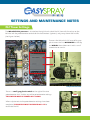
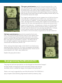
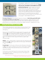
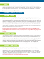
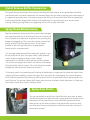
SETTINGS AND MAINTENANCE NOTES
ASYSPRAY
SETTINGS AND MAINTENANCE NOTES
PLC Timer Settings:
ASYSPRAY
The Mitsubishi PLC processor is situated on the right hand side of the PLC box with the relays on the
left side and the potentiometer controls for the head motors (spinners) and pumps down the middle.
(See Figure 1 below).
To access the Mitsubishi PLC ease off its grey
plastic cover that has MITSUBISHI at the top
and MELSEC down below on it with a small
screwdriver or similar.
Figure 1
Grey Cover Removed
There is a small grey plastic switch to the right of the two
potentiometer dials. To alter any of the potentiometer settings
ON
THIS SWITCH MUST BE TURNED OFF = DOWN.
When adjustments to the potentiometer settings have been
completed, THIS SWITCH MUST BE TURNED ON = UP to
reactivate the PLC.
OFF
The upper potentiometer controls the priming time (this is the
time the pump works to feed chemical from its bottle through to
the spray head). This same timer also applies to the reversing of
the chemical and the primary feed through of cleaner. It must be
adjusted to take into account the length of pipe from the chemical
box through to the spray head so that the pump switches off just as
the chemical reaches the head.
Figure 2a
This (upper) potentiometer has ten segments on its dial and a cross
with two dots straddling one line of this cross. (See Figure 2a) It
is this line that is its pointer. It may alternatively have an arrowhead. Starting from zero seconds, each segment on the dial adds 7.6
seconds to the timer, moving clockwise, up to a maximum of 76.5
seconds fully clockwise. In rough terms a short run of tube needs
about 20 seconds prime time or the fourth mark (3 segments) on
the dial from the bottom left zero mark going clockwise. A longer
run of 5 metres such as the rear of a Swingo needs about
60 seconds or the ninth mark (8 segments) on the dial clockwise.
The lower potentiometer controls the second or final wash
time. This is the timing of the final flush out with cleaner after
it pauses following priming through with cleaner. This timer
gives 7.6 seconds for each segment on the lower potentiometer
dial. Two segments give about 15 seconds. The fifth mark on
this dial (four segments) moving clockwise, gives about 30
seconds of final wash out, which is OK.
When settings have been made switch the PLC unit back on by
moving the grey switch up. This causes a temporary activation
of the pump even though the key operated power switch on the
control panel is off. Don’t worry about this.
Replace the grey plastic cover.
Re-programming the Mitsubishi PLC:
The program and timer parameters can be changed and have been changed
on later models to improve the wash cycle and extend pump timings
available, which is needed for longer runs of pipe to the spray head.
Earlier units can be upgraded by use of the Mitsubishi FX1N-EEPROM-8L
plug in eprom (Electronically programmed read only memory) chip.
Figure 2b
Figure 4
To re-program / update a PLC, remove the front cover to
expose the inside and then disconnect all power. Switch
the main PLC unit ON/OFF switch DOWN into the OFF
position (See Figure 4). Plug the eprom unit into the
matching slot on the PLC. Make sure that the Protect
Switch is in the ON position to prevent accidental
overwriting of the eprom memory. Turn on the power to
the PLC. Press the WR (Write) button on the eprom once.
The WR green LED should illuminate. Press the WR
button a second time and the green LED will flicker as the
new program is downloaded into the PLC.
Disconnect the power, then unplug the eprom and remove it. Switch the grey On/Off switch
on the PLC back ON into its UP position. Re-connect the power supply and the PLC will be
re-programmed and ready to go. You will now need to check and adjust the pump timing
potentiometers as new parameters will have been loaded into the PLC. Replace the PLC cover.
Pump & Head Motor Controls:
There are four potentiometer controls down the centre of the PLC box
on a metal bracket. This is just to the left of the Mitsubishi PLC unit.
(See Figure 5)
Moving from TOP to BOTTOM, the top pot controls the pump for wide
spraying ( P), the next one down controls the spray width for wide
spraying ( S), the third down controls the pump for narrow spraying
( P) and the bottom pot controls the spray width for narrow spraying
( S). Anti-clockwise reduces output and clockwise speeds up or
increases output.
Widths: Unless a special width is required, adjust the wide spray width
(2nd pot down S) to about 50cm and the narrow spray width (bottom
pot S) to about 30cm.
Pump Outputs: For the 50cm wide spray, the wide pump setting (top
pot P) needs to give 45 millilitres per minute, which equates to about
41RPM on the pump. Time and count the revs or use a measure to
measure the output.
For the 30cm narrow band spray the narrow pump setting (3rd pot
down P) needs to give 27 millilitres per minute, which equates to
about 25RPM at the pump.
Figure 5
These settings are all calibrated for a vehicle forward speed of 6 KPH. Which can vary according to client
requirements. Please ask for revised settings if so.
Fuses:
There are two fuses within the PLC control box. The one at the top on the left, above the relays,
protects the motor circuits for the spray heads and pumps. This is a 2 amp fuse. The one at the top
on the right protects the Mitsubishi PLC. This is a 400 milliamp fuse. Remove this to disconnect
power to the PLC when re-programming.
OTHER MAINTENANCE NOTES:
Breather Valves:
The breather valves on the end of the nylon probe tubes that go into the chemical and cleaner
bottles can seize up, especially when not used for long periods of time. The chemical can dry onto
the seals gluing them shut. Take a short length of peristaltic rubber tube and press this against the
coned end of the breather valve. Sucking on this should draw air through and blowing should not
allow any air back through it. If there is no air passing when sucked, sharply bang the side of the
valve housing against some hard object and re-test until it operates freely. This tends to free the
rubber washer inside that has sealed shut and glued itself in place with dried on herbicide. Test it
again by sucking and blowing to check it works OK.
Symptoms of breather valve failure are collapsed bottles that are being sucked flat by the
pump and in extreme circumstances the spray output can be stopped while the pump is still
running.
Peristaltic Pump:
The tubing in the peristaltic pump head should be renewed each year after the winter break and
before spraying. This can be done by removing the pump head (2 screws) and dismantling it, or
for speed and convenience, replace the whole plastic pump head. When replacing the pump head
note the two rubber washers that fit between the pump head and the mounting plate are
replaced. These allow the pump head to float and so the two screws that hold the head on should
be dipped in Locktite and not tightened down fully, just gently pinched. Run the pump and
slacken these screws off so that the pump runs most smoothly then leave the Locktite to set.
Solenoid 3-Way Valve:
This valve, situated inside the pump box switches between chemical and cleaner and can
occasionally stick or block, usually after lying idle over winter, or if users have not removed
chemical when not in use. Failing to remove the chemical allows deposits of titanium dioxide
powder to fall out of suspension and create solids that can block the valve orifices. If the pump is
working but not drawing fluid, check the breather valves first as above. If this does not solve the
problem, dismantle and clean the solenoid valve.
DO NOT LEAVE CHEMICAL CONNECTED WHEN NOT SPRAYING.
Quick Release Bottle Connectors:
The quick release connectors that connect the chemical and cleaner to the pump box should be
washed off after use when chemicals are removed from the unit after spraying and stored away in
an approved pesticide store. Occasional spray with WD40 will maintain their efficient operation.
If left connected for long periods of time with chemicals in them they can seize up and need
freeing. Moving spring release and applying WD40 will usually free them.
Spray Head Maintenance:
Regular automatic cleaning by the system helps elongate
the spray head life, but it also helps if the user washes off
dust, chemical and road dust to prevent the spinning disc
becoming clogged up. The spray disc can be removed by
gently prising it off the spinner shaft. If the motor
spindle is not running freely than a replacement
motor head is recommended.
It is strongly recommended that when the sprayer is out
of use (most of the year) the spray head is kept covered
with a drawstring bag to keep it clean. Motor
replacement is a factory return job and the best option
is a service exchange head, which will have a new motor
fitted and fully sealed in place. This will isolate the motor
completely from moisture, chemical and dust.
If the spray head is not working well, leading to blobbing or stringing of the chemical rather than
a pattern of finer droplets, remove the spray disc and wash this thoroughly. Also wash deposits
of dirt off the bottom of the head and from around the disc spindle hole. When replacing the disc
push fully on. Try easing it down (off) about 1mm to 2mm to allow a small clearance if it does not
spin freely. Check that it spins freely by hand.
Spray Arm Pivots:
The spring-loaded serrated discs that allow the spray arm to move
should be cleaned and greased with a spray grease to maintain free
movement at least once a year. Also check the movement of the
other pivots on the arm and adjust the pinch bolts to ensure they
can be moved, but are not too free so that the arm does not stay in
place when moved.
PKS ANNUAL SERVICE RECOMMENDATIONS
1.
Check condition and security of all wires and pipes between units and spray head. Repair or replace if damaged.
Check for any leaks or worn pipes and mend / replace. Cable tie securely.
2. Replace peristaltic pump head and pump tube. Undo the two securing screws on the head and the cable ties on
the pipe joints and replace with a new unit. Replace two screws making sure that they have Locktite on threads
and that the small rubber cushion washers between the pump and back plate are in position. Screw down the
two screws until the rubber washers are only just pinched then release the screws a quarter turn. The pump head
must be free to move. After replacing the cable ties on the pump tubes, wedge a small length of 15 mm plastic tube
across between the two pump tubes and the back plate. This lifts and holds the pump head so that it is square on
to the gearbox motor shaft and gives a more even action when pumping.
3. Check the breather valves on both vent tubes to ensure the one-way release valves are free and working OK. A
sharp tap on a hard surface will generally free up the rubber seals that can stick down onto their seats when left
for some time. Test the valves by holding a short length of silicone tube over the valve cone and blowing then
sucking. On blowing, there should be no movement. On sucking, air should be pulled through the valve freely.
4. Check the action and freedom of the dry break connectors onto the pump box. Clean and lubricate or if seized up,
replace with the later nylon types. Check that o-ring seals on connectors are OK or replace.
5. Clean and grease the pivot plates on the spray arm. Grease and tighten all pivot joints on the spray arm so that
they can be moved under firm pressure but will stay in place when in use.
6. Clean the spray head and replace the spinning disc. Power up the system and check the free and quiet rotation of
the motor head. Replace if noisy, sticking, slow or not working. Replace all old type CDA heads or if sealed with
white silicone under the dust cap.
7. Upload the new timer program into the Mitsubishi PLC if old model (See service manual)
8. Connect up cleaner and calibration fluid and turn the system on. Check that the prime time takes the fluid just up
to the spray head then stops. Re-adjust timer on PLC to ensure that it does. Also check secondary wash timer is
still OK. (See service manual)
9. If old motor and gearbox (50:1 ratio) is fitted, recommend that client updates to new 80:1 ratio motor / gearbox
unit and has the system re-calibrated to 9 L/Ha rather than 15 L/Ha, saving 40% on chemical.
10. Check that pump speed on narrow is still OK and that width is approx 30cm. Remove disc and measure output in
millilitres per minute to verify correct calibration against charts. (Now 9 L/Ha)
11. Check that pump speed on wide is still OK and that width is approx 50cm. Remove disc and measure output in
millilitres per minute to verify correct calibration against charts. (Now 9 L/Ha)
12. Turn off and wash through. (Automatic).
13. Replace spray head cover / drawstring bag if worn or torn.
14. Clean and check over the unit replacing the PLC unit lid and securing in place.
15. MAKE SURE THAT AFTER REPROGRAMMING AND TIMER ADJUSTMENTS PLC SWITCH IS BACK ON (UP).
16. After turning off the system for its final close down, check that the reverse pump returns herbicide to its
container and that the solenoid then switches over to cleaner and flushes this through the system. If
solenoid does not operate strip and clean it.
FOR WINTER STORAGE, REMOVE ALL CHEMICAL AND CLEANER, SWITCH ON,
WAIT TWO MINUTES AND SWITCH OFF.
This will evacuate all liquid to prevent frost damage.
ASYSPRAY
SprayCDA
Allscott Park, Allscott, Telford, Shropshire, TF6 5DY
T: 01952 897414
E: [email protected] W: www.spraycda.com