1
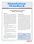
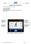
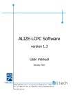
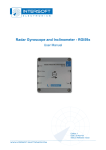
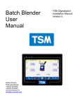
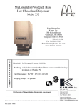
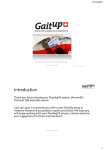
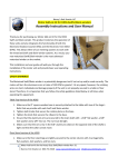
CP9000 Quick Start Manual Instant Access Parts and Service +35342 9335560 +35342 9334422 www.tsmcontrols.com [email protected] CP9000 Quick start 1. Power on, When you turn on the computer and it will automatically boot to this screen. Entering a recipe. Touch Then, Then Touch the “New” option Last Modified 22/09/14 Page - 2 CP9000 Quick start Enter the recipe name. The recipe should be calculated as per the diagram below. Line Total G/M Layer A % A C.1 A C.2 A C.3 Layer B % A C.4 Grams per meter B C.1 B C.2 B C.3 Layer C % B C.4 C C.1 C C.2 = 2 * Lay Flat Width(M) * Layer Average Density* thickness Last Modified 22/09/14 Page - 3 C C.3 C C.4 CP9000 Quick start The ‘Edit Recipe’ dialog will have a ‘Common’ tab (with data common to all of the layer’s on the system) and a tab for each of the layer’s on the system (with data specific to each individual layer). The ‘Common’ tab consists of numerous edit boxes in which you can enter the values for the recipe. The ‘Order Weight per Length (Grams per meter)’, the ‘desired and trim width’ and are necessary There are 4 important things to be entered on this page. 1. Layer percentage must be entered for each extruder. 2. Component percentages. (Component 1 is calculated automatically) 3. Material densities. 4. Job RPM (used to ramp the extruders in proportion). This screen is where the parts of the recipe that are common to the line are entered. (Descriptive) Not necessary for the recipe Last Modified 22/09/14 Page - 4 CP9000 Quick start Individual layers Enter the layer percentage for the extruder by touching the extruder tab There are 4 important things to be entered on this page. 1. Layer percentage must be entered for each extruder. 2. Component percentages. (Component 1 is calculated automatically) 3. Material densities. (If the density is not entered then a default of 0.92 is used) 4. Job RPM (used to ramp the extruders in proportion). This feature is used for ramping all of the extruders together. When starting the line the extruders can be ramped as a percentage of the job rpm so that the extruders will ramp with approximately the correct layer ratio and therefore save time on start-up Use the layers. tabs to enter the set points for the other Touch the “ok” icon to close the recipe. Last Modified 22/09/14 Page - 5 CP9000 Quick start Starting a recipe. Once a recipe has been entered it has to be placed into the order queue before it can be started. To do this touch the back arrow to go to this menu Touch to open the order queue. Touch the “Add” option and select a recipe from the list. The recipes must be entered in the sequence that: The recipe next recipe to be started should be entered into the Queue last. Save the changes to the Queue when all the recipes have been entered. Go back to the main screen and use the icon the view the next recipe to be started. A summary of the set points in the order are displayed on this screen. You have the option to start the order or to abort. Current order. Once a recipe can be started it can be edited using the current order icon. Any changes to the recipe are not saved when they are changed using this function. Last Modified 22/09/14 Page - 6 CP9000 Quick start Ramping the extruders. To adjust the extruder speed there are 2 icons that can be used to open the “ramp” screen Extruder Motor Ramping Individual extruders: The top icon allows the extruder to be switched between manual and auto. (If the extruder is in manual the icon will display AUTO and if the extruder is in auto made the Icon will display MANUAL.) There is a small time delay when the Auto/manual option is selected. This is to allow the blender time to change to auto and send the confirmation back to the CP2000. Touching the “Set RPM allows the user to select the desired RPM for the extruder.” To do this: 1. Touch the SET RPM icon. 2. Enter the desired RPM. 3. Save the change. 4. Confirm the extruder speed download. Last Modified 22/09/14 Page - 7 CP9000 Quick start The extruder can be increased or decreased by touching the or . JOB RPM. When a recipe is running correctly this function allows the user to enter the current RPM of the extruder. If the “all layers ” function is used to change the extruder speed the extruders will ramp in proportion to each other. E.G. if extruder A has a job rpm of 50 and extruder B has a job rpm of 100. When the “ALL LAYERS ” function is used to jump to a percentage of the rpm, if 25% is entered then extruder B will ramp to 12rpm and extruder A will ramp to 25rpm so that the layer percentages should be almost correct from startup. ALL LAYERS. The top icon allows the extruder to be switched between manual and auto. (If the extruder is in manual the icon will display AUTO and if the extruder is in auto made the Icon will display MANUAL.) RPM% This allows the user to ramp all of the extruders to a percentage of their job rpm. If the extruders have a job rpm of 80 and you touch the RPM% icon and enter 50% all the extruders will jump to 40 rpm. All of the extruders can be increased or decreased by touching the arrows. Last Modified 22/09/14 Page - 8 or CP9000 User Manual Instant Access Parts and Service +35342 9335560 +35342 9334422 www.tsmcontrols.com [email protected] CONTENTS 1. Run the TSMCP9000NT Application …………………….. 2. 2 Mimic Hot-Spots 2 Main Mimic Hot-Spots …..………………………….. 5 2.1 3. 4. 5. 6. Blender Mimic ……..…………………………………….. 5 2.2 Motor Mimic ……..…………………………………….. 7 2.3 Bubble Mimic ……..…………………………………….. 10 2.4 Winder Mimic ………………………………………….… 11 Mimic Client Toolbar 3.1 Toolbar #1 ……………..…………………………….. 12 3.2 Toolbar #2 ………………..………………………….. 16 3.3 Toolbar #3 ……..…………………………………….. 18 3.4 Toolbar #4 ………………………………..………….. 21 3.5 Toolbar #5 ……..…………………………………….. 23 Creating a Label Format File ………………………………….. 27 End of Order Function ...…………………………………….. 31 Wiring Overview .……………………………………………...32 1. Run the TSM CP9000 Application. There are two separate application’s needed to run the CP9000 (the Server application and the Mimic Client application) both must be executed to run the TSMCP9000 application. Normally these are automatically loaded when the pc is started up. There is a delay built into the auto start routine to allow the pc enough time to initialize its communications ports. INSTRUCTIONS for manually starting the Server application): 1. The Server application must be loaded before the Mimic Client. The Mimic Client will not load if the Server is not running. 2. To manually execute the Server application, select the ‘Start’ Menu on your system. Use the “Run” command from the Start menu as shown in figure 2. figure 2 When the server starts it will open the following window. figure 3. Last Modified 22/09/14 Page - 3 INSTRUCTIONS (for the Mimic Client application): 1. To execute the Mimic Client application select the ‘S9KMimic Client’ option from the ‘Start’ Menu on your system. 2. As long as the Server has already been started, the Mimic Client will start to load. It may take the Mimic Client several seconds to load completely. 3. Once the Mimic Client has loaded you may begin using the system Last Modified 22/09/14 Page - 4 Mimic client This is an example of the mimic with a 3 layer line display. Last Modified 22/09/14 Page - 5 2. Mimic Hot-Spots. The following is a list of what hot-spots can be found on the Mimic. Hot-spots are areas on the screen where the user can touch to initiate some event. Blender Mimic. Touching a Blender on the main mimic will change the view from the Main Mimic to the Blender Mimic view. There may be more than one blender, therefore the blender details to be displayed on the Blender Mimic will be the details for the blender that you have selected on the main mimic. Extruder Motor 2.1 Blender Mimic This screen shows the set and actual percentages for the individual components of the selected blender Last Modified 22/09/14 Page - 6 Hopper Touching a hopper on the Blender Mimic will display the Blender Setpoint dialog. ?This box allows the user to adjust the setpoint for this component. (see figure 5). figure 5 Warning: these changes will only be made to the current order. They will not be saves into the recipe file. Last Modified 22/09/14 Page - 7 Blender Mimic Touching the Blender mimic will display the Setpoint dialog for the extruder that the blender is connected to (see figure6). The Extruder’s set point dialog displays the ‘throughput’ setpoint, which you may not change, and the ‘Screw Speed’ that you may set. You can either use the plus & minus buttons or simply type in the screw speed value in the ‘Screw Speed’ edit box to set this value. NOTE: The button beside the ‘Exit’ button may be toggled between ‘Manual’ and ‘Auto’. Only when the ‘Manual’ button is switched on can you adjust the screw speed. Last Modified 22/09/14 Page - 8 figure 6 2.2 Motor Mimic Touching a Motor (or the “Ramp all Motors” icon) on the main mimic will display the Ramp All Motor’s dialog. This will allow you set the ‘RPM’ values for each of the layers individually. Or change all of the extruder speeds together. You may also set the mode of operation to ‘Manual’ or ‘Auto’. This is also done for the Width if there is one present on the system see figure 4 below. Last Modified 22/09/14 Page - 9 Ramping Individual extruders: The top icon allows the extruder to be switched between manual and auto. (If the extruder is in manual the icon will display AUTO and if the extruder is in auto made the Icon will display MANUAL.) Touching the “Set RPM allows the user to select the desired RPM for the extruder.” To do this: 1. Touch the SET RPM icon. 2. Enter the desired RPM. 3. Save the change. 4. Confirm the extruder speed download. The extruder can be increased or decreased by touching the or . JOB RPM. When a recipe is running correctly this function allows the user to enter the current RPM of the extruder. If the “all layers ” function is used to change the extruder speed the extruders will ramp in proportion to each other. E.G. if extruder A has a job rpm of 50 and extruder B has a job rpm of 100. When the “ALL LAYERS ” function is used to increase the extruders together extruder B will ramp at twice the rate of extruder A so that the layer percentages should be almost correct from startup. ALL LAYERS. The top icon allows all of the extruders to be switched between manual and auto. (If the extruder is in manual the icon will display AUTO and if the extruder is in auto made the Icon will display MANUAL.) RPM% This allows the user to ramp all of the extruders to a percentage of their job rpm. If the extruders have a job rpm of 80 and you touch the RPM% icon and enter 50% all the extruders will jump to 40 rpm. All of the extruders can be increased or decreased by touching the . Last Modified 22/09/14 Page - 10 or 2.3 Bubble Mimic Touching the bubble on the main mimic will change the view from the Main Mimic to the Bubble Mimic view. In this view you will be able to see & change the bubble ‘width’ and ‘thickness’, if there is a width controller and profiler configured. The calibration data for both may also be viewed and modified. Bubble (Will only work if a TSM width or control or a thickness profiler system is configured) Last Modified 22/09/14 Page - 11 2.4 Winder Mimic Touching the Winder on the main mimic will change the view from the Main Mimic to the Winder Mimic view. This view will allow you to view the front/back ‘roll length’ for the front & back winders, respectively. Back Roll Length/Weight Front Roll Length/Weight Winder Mimic Hot-Spots. Front WinderTouching the Front Winder on the Winder Mimic will display the Front Winder’s Setpoint dialog, which will display the Front ‘Roll length’ and will allow you to set its value. Back Winder Touching the Back Winder on the Winder Mimic will display the Winders Setpoint dialog, which will display the Back ‘Roll length’ and will allow you to set its value. Last Modified 22/09/14 Page - 12 3. Mimic Client Toolbar. The TSMSigmat9000NT Mimic Client application consists of two main features:1. The Mimic. 2. The Toolbar. The previous sections of this manual described the Mimic part of the application, the hotspots that can be found on the mimic and what the user can access from the Mimic. This section will discuss the Toolbar that accompanies the Mimic. The Back icon on the Toolbar is separate from the Back icon on the Mimic. The Back icon on the Toolbar takes you back to the previous toolbar. 3.1 Toolbar #1. When you start the Mimic Client application the toolbar in (figure 12) will be the initial toolbar. figure 12 There are 7 icons on the Toolbar, some of which will take you onto another toolbar, while some perform a specific function. Last Modified 22/09/14 Page - 13 The Alarms icon allows you to view the alarms in the system (see figure 13). figure 13 Any alarms that occur on the 9000 will be displayed here. All of the alarm details will be displayed in column format. If you select the Acknowledge Alarm button on the view, the Condition tab on the view will signify that the alarm has been acknowledged. Otherwise it will signify that it is in alarm. Selecting the Acknowledge Page button will set the Condition field for all the alarms to signify that each alarm has been acknowledged. Last Modified 22/09/14 Page - 14 The Next Order icon displays the next order in the queue, and some details about the data on the order. It also allows you to Start the Order, by clicking the ‘Start Order’ button on the dialog (A recipe must be placed in the queue before this function can be used)see figure 14. figure 14 The Recipes icon takes you onto Toolbar #2, which contains all the functions exclusively relating to Recipes ( Queue, Learn, Edit Recipes). The Reports icon takes you onto Toolbar #3, which contains all the functions exclusively relating to Reports ( Roll, Order, Shift Reports ). Last Modified 22/09/14 Page - 15 The Current Order icon displays the order that is being used. It brings up the Current Order dialog which displays all the common data between all of the layers on the system and also the data unique to each individual layer (see figure 15). figure 15 figure 15 shows the Current Order. You can see that there are several tabs to chose from at the top of the dialog. The first tab’s page displays all the data Common to all layers on the system. If you were to select any of the next 3 tab’s you would see the data specific to each layer (i.e. Extr A - Extr C). If you make any changes, then the system will download all of the changes. These changes are not saved in the recipe. Last Modified 22/09/14 Page - 16 The System icon will take you to Toolbar #4, which will allow you Exit the application and deal with other system related functions. The Language icon will alternate the system software text between its default language setting and English. 3.2 Toolbar #2. Toolbar #2 deals exclusively with Recipes, and it is initiated from the ‘Recipes’ icon on Toolbar#1. figure 16 As you can see there are five icons to chose from, each carrying out a different function. The Back icon will take you back to Toolbar #1 from where this toolbar was initially called. The Files icon will take you onto Toolbar #5, which deals with all Recipe files generated by the System ( copy, delete, rename, edit files ). Last Modified 22/09/14 Page - 17 The Queue icon, if enabled, will allow you to view the current state of the recipe Queue. It will also allow you to add and delete recipe files from any position in the queue. The recipe at the top of the queue will be displayed in the ‘Next Order’ dialog discussed under ‘Toolbar #1’, and thus will be the next recipe to be loaded. (see figure 17). figure 17 The Learn icon will allow you to update a specific recipe file with the current process setpoints. You may not however learn setpoints into a file that is currently in the order queue. You can learn the current recipe, an existing recipe or a new recipe. When you are finished select the ‘Done’ button (see figure 18). figure 18 Last Modified 22/09/14 Page - 18 3.3 Toolbar #3. Toolbar #3 deals exclusively with Reports, and it is initiated from the ‘Reports’ icon on Toolbar#1. figure 21 The Back icon will take you back to Toolbar #1 from where this toolbar was initially called. The Rolls icon will allow you to view any Roll Reports that have been created by the system. These reports are stored ‘Roll Reports’ directory:\\Sigmat9000\Reports\Roll Reports. You can select the report you wish to view (example - figure 22). figure 22 Last Modified 22/09/14 Page - 19 The Orders icon will allow you to view any Front Roll Reports that have been created by the system. These reports are stored ‘Order Reports’ directory:\\Sigmat9000\Reports\Order Reports. The Shifts icon will allow you to view any Shift Reports that have been created by the system. These reports are stored ‘Shift Reports’ directory:\\Sigmat9000\Reports\Shift Reports. The Events icon allows you to view any alarms or events that have taken place on the 9000. From the Configuration Manual you will remember that we configured two Alarm Annunciators, an Alarm Text Annunciator and an Alarm Beacon. The Alarm Text Annunciator creates alarm files that contain the exact details that can be found in the Alarm view. Selecting this option allows you to view the contents of the Alarm Text files that have been previously created. Once you select this icon, you are presented with a list of all the alarm log files on your 9000 (see figure 23). figure 23 You select the file you wish to view and it will be opened with the same view that displays the current alarms that are in the Alarm view. Last Modified 22/09/14 Page - 20 figure 24 shows an example of the type of details that are stored in the Alarm log files. figure 24 The Summary icon allows you to view any summary reports that have taken place on the 9000. These reports are a ‘snap-shot’ of the production variables when the reports are generated. The Recipes icon allows you to view the recipe files that are stored on the Sigmat 9000. However, the recipes cannot be edited from here. It is designed as a view only option so that operators can check the settings of a recipe file before implementing a download function. Last Modified 22/09/14 Page - 21 3.4 Toolbar #4. Toolbar #4 deals with system specific details, and it is initiated from the ‘System’ icon on Toolbar#1. To gain access to this tool bar enter: Username: administrator Password: tsm figure 25 The Back icon will take you back to Toolbar #1 from where this toolbar was initially called. The Print icon will generate a screen print function, i.e. all data visible on that particular screen will be printed via the default printer as configured on the system. The Diagnostics icon displays the Counters for all of the Controllers on the system. You can use this option to check that all of your controllers (devices connected to the system) are communicating with the system properly (see figure 26). figure 26 From figure 26 you can see that we are checking the diagnostics for one of the Blenders connected to the system (A list of all the Controllers running on the system are shown in the ‘Diagnostics For:’ drop-down list). If the ‘Timeout Count’ or ‘Checksum Error Count’ are high, then you will know that the controller is not communicating properly, if at all. Last Modified 22/09/14 Page - 22 The Password icon allows you to set up 3 levels of Password protection on your Sigmat9000NT application. This is to stop unauthorized people from accessing and modifying critical data on the system. You must type in the Administrator user name and password to set or change the password settings. figure 27 Figure 27 shows that there are three levels of password protection available for you to set. To set the Password you must specify the old password, then if the old password is valid, you can type in the new password. The three levels of password are: Administrator - No restrictions Supervisor Restricted from changing usernames and passwords and also restricted from system calibration parameter’s. Operator May only download orders and view reports, recipe files and production summary data. Restricted from editing recipes, the System toolbar and calibration settings. The Mapping icon allows you to set up the Vacuum systems Sequencer Mapping. (If a TSM vacuum loading system is configured) The Exit icon is used to Exit the Client application. Last Modified 22/09/14 Page - 23 3.5 Toolbar #5. Toolbar #5 deals specifically with recipe files, and it is initiated from the ‘Files’ icon on Toolbar#2. figure 28 The Back icon will take you back to Toolbar #2 from where this toolbar was initially called. The Edit Files icon allows you to select a recipe file from the list of all recipe files generated by the system (stored at ‘Sigmat9000\Recipes’), and edit its details (see figure 29). figure 29 shows that the system has 3 extruders connected (Extr. A, B, and C) figure 29. Last Modified 22/09/14 Page - 24 Recipe Entry. (This section is already covered in the Quick start section) Touch , then ,then This option allows you make a new recipe file or edit an existing file When you select the recipe file that you wish to edit, the ‘Edit Recipe’ dialog will come up (see figure 29 on page 28). The recipe should be calculated as per the diagram below. Line Total G/M Layer A % A C.1 A C.2 A C.3 Layer B % A C.4 Last Modified 22/09/14 B C.1 B C.2 B C.3 Page - 25 Layer C % B C.4 C C.1 C C.2 C C.3 C C.4 The ‘Edit Recipe’ dialog will have a ‘Common’ tab (with data common to all of the layer’s on the system) and a tab for each of the layer’s on the system (with data specific to each individual layer). The ‘Common’ tab consists of numerous edit boxes in which you can enter the values for the recipe. The ‘Order Weight per Length (Gramms per meter)’, the ‘desired and trim width’ are necessary Grams per meter = 2 * Lay Flat Width * Layer Average Density * thickness Individual layers There are 4 important things to be entered on this page. 1. Layer percentage must be entered for each extruder. 2. Component percentages. (Component 1 is calculated automatically) 3. Material densities. 4. Job RPM (used to ramp the extruders in proportion). Last Modified 22/09/14 Page - 26 The Copy Files icon allows you to create exact copies of existing recipe files, giving the copied version a different name (see figure 30). figure 30 shows the Copy files dialog. I have selected the file ‘HeatUp.stp’ which I want to copy. I must give it a name other than ‘HeatUp.stp’ (i.e. ‘Copy of HeatUp.stp’). Select the Copy button and the file will be copied. figure 30. The Rename Files icon allows you to rename existing recipe files (see figure 31). Last Modified 22/09/14 Page - 27 figure 31. Select the file you wish to rename and type in the new name you wish to give it. From figure 31 you can see that I am renaming the file ‘copy test.stp’, which I created in the previous section, as ‘test test.stp’. Click the Rename button and the file will be renamed. Click OK when you are finished. The Delete Files icon allows you to delete recipe files that you no longer need. Select the file you wish to delete and select the Delete button to delete it. The Label Setup icon allows you to create your own Label formats, which will be created and printed for each roll that is made. When you crate the label it will be stored in the ‘Labels’ directory which is a subdirectory of ‘Sigmat9000’. Once you select the Label Setup icon you will be presented with a list of label files. If this is the first time you have entered the Label Setup option there will be a default label file listed which you may open and modify (see figure 32). Last Modified 22/09/14 Page - 28 figure 32 Open the label file of your choice, and the ‘Create New Label for printing’ dialog will appear (see figure 33). figure 33 Type in your Label format details (see Section - Creating a Label Format File) in the text box given, and select the ‘Save’ button to Save the file. You may do a ‘Test Print’, on your new label details. Last Modified 22/09/14 Page - 29 4. Creating a Label Format File. On Toolbar #5 there is a function that allows you to create your own label format file’s. We have already discussed how to open and modify a label file, but how does the system know where to display actual values from a Roll Report, on the Label. This section describes the parameter’s used to identify the values and the mechanism for doing this. Format the Order Details. Say, for example, that you wanted the Label to display the following details from an order: Roll Side Line Speed Number of Slits Order Weight Throughput Roll Weight 0 (see Parameter List below) 1 3 28 31 33 TSM’s parameter list. ROLL SIDE LINE SPEED TRIM FED NUMBER OF SLITS ROLL NUMBER WIDTH SETPOINT TRIMMED WIDTH SHEET TUBE ORDER LENGTH ROLL LENGTH START YEAR START MONTH START DAY START HOUR START MINUTE START TIME START DATE END YEAR Last Modified 22/09/14 0 1 2 3 4 5 6 7 8 9 10 11 12 13 14 15 16 17 END MONTH END DAY END HOUR END MINUTE END TIME END DATE DURATION DAYS DURATION HOURS DURATION MINUTES DURATION TIME ORDER WEIGHT WEIGHT AREA WEIGHT LENGTH THROUGHPUT WINDER WEIGHT ROLL WEIGHT REEL WIDTH GAUGE SETPOINT DESCRIPTION 1 DESCRIPTION 2 Page - 30 18 19 20 21 22 23 24 25 26 27 28 29 30 31 32 33 34 35 36 37 Create the Label Format File. In the parameter list we have highlighted the values we wish to display on the Label. (Any value listed on the ‘Parameter List’ can be displayed on the Label). Type in the sample label given below in the text box on the ‘Create New Label for printing’ dialog, and Save it. ========================================= Roll Side: [0] Line Speed: [1] Number of Slits: [3] Order Weight: [28] Throughput: [31] Roll Weight: [33] ========================================= NOTE: When you edit a recipe you must specify what Label file you wish you wish to use when printing its label’s. (See figure 26 - Edit Recipe Dialog). On the ‘Edit Recipe’ dialog you can select the label file of your choice from the drop-down list box. Whenever a roll report occurs a label will be drawn up and printed out. Wherever you have [] containing a number that is in the parameter list, Sigmat9000 will insert the correct value in place of the parameter list number and its []’s. So, in our example when the system is drawing up the label it sees the [0], and it knows that this represents the 'Roll Side’. It gets the ‘Roll Side’ value from the Order report and displays it in place of [0]. The printed version will look like this (assume the values are correct). ========================================= Roll Side: Front Line Speed: 20 Number of Slits: 4 Order Weight: 1200 Throughput: 200 Roll Weight: 300 ========================================= NOTE: The use of the [] brackets is essential to the whole operation as is using the correct number from the parameter list to identify the different values that you wish to display. Last Modified 22/09/14 Page - 31 6. End of Order Prompt. During the course of an order you may wish to be notified about how long the Order has to run. The 9000 system provides an option that displays a Message Box on the Mimic Client, when there is less than thirty minutes remaining on the Current Order. The Configuration allows you to specify whether or not the Message is displayed. By default it is set on. When it is set on, the system periodically calculates how long there is left on the order, and when it sees that there is less than thirty minutes left the following message is displayed. Last Modified 22/09/14 Page - 32 CP9000 wiring overview Last Modified 22/09/14 Page - 33