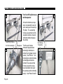
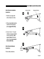
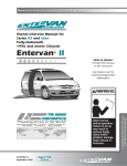
1
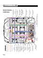
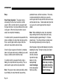
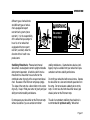
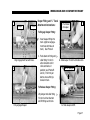
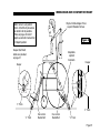
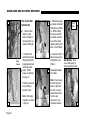
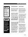
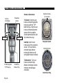
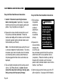
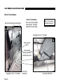
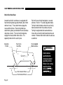
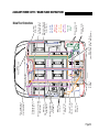
R
BRAUN CONSUMER
Operator's
Manual
WARNING
Wheelchair-Accessible
Lowered Floor Conversion
Ope
ra
Man tor'
ua s
l
featuring 2004
©
DaimlerChrysler Minivans
International Corporate Hdqrs: P.O. Box 310 Winamac, IN 46996 USA
1-800-THE LIFT
(574) 946-6153
FAX: (574) 946-4670
March 2004
Read manual
before operating.
Failure to do
so may result in
serious bodily
injury and/or
property damage.
Keep manual in
Entervan.
®
30117
®
®
Consumer Entervan ®
featuring 2004
DaimlerChrysler Minivans
"Providing Access to the World"
Congratulations
We at The Braun Corporation wish to express our fullest appreciation
on your new purchase. With you in mind, our skilled craftsmen have designed and assembled the finest lowered floor vehicle available.
This manual includes safety precautions, operating instructions, manual
operating instructions, and instructions for maintenance and lubrication
procedures.
Your Entervan® is built for dependability, and will bring you years of
pleasure and independence, as long as the maintenance is performed regularly and the Entervan® is operated by an instructed person.
Sincerely,
THE BRAUN CORPORATION
Ralph W. Braun
Chief Executive Officer
2005 ENTERVAN SUPPLEMENT 30750
Subject: 2005 Entervan
Effective: June 2004
If you have a 2004 Entervan,
disregard this supplement.
Read this supplement and the
manual if your Entervan is a
2005 Chrysler conversion.
Contact your sales representative
or call The Braun Corporation at
1-800-THE LIFT if any of this
information is not understood.
Operation Sequence: Entervan
power door, ramp and kneel functions are activated by pressing and
releasing any control switch (as
detailed in this manual). Operation
sequence for the 2005 Entervan is
as follows.
Open Functions: When activating
the Open functions, the power door
opens, the ramp unfolds and the
kneel system then lowers the rear
of the vehicle.
Close Functions: When activating
the Close functions, the ramp folds
first, and then the kneel system and
the power door are activated
simultaneously.
Kneel On-Off Feature: The kneel
“On-Off” feature outlined on page
14 of this manual is not applicable
for the 2005 Entervan conversion.
The kneel system is active at all
times.
Mechanical Kneeling Override:
In the event the Entervan is in the
kneeled position and you experience power or equipment failure,
the Kneel Actuator Manual Release
(Override) feature allows the rear
of the vehicle to be raised to the
normal position.
The 2005 conversion is not
equipped with the black T-Handle
addressed on page 15 of this
manual. A release handle is
located under the rear bench seat.
To Release Kneel: Pull release
handle forward and down.
To Engage Kneel: Pull release
handle forward, lift and push
handle rearward.
Page 1
2005 ENTERVAN SUPPLEMENT 30750
Front Seats: In an effort to
produce vehicles that can be
configured to meet a variety of
customer needs, the driver and
passenger seat bases have
been designed so they may be
removed.
WARNING
Do not place
anything on seats
removed from the
vehicle. Doing so
can disable the
occupant classification system (OCS)
safety feature. A
disabled OCS may
result in serious
bodily injury and/or
property damage.
Page 2
Note: Driver and passenger side
front seats are not interchangeable.
Remove and install front seats as
detailed on pages 32-40 of this
manual.
start the vehicle. Let the
vehicle idle one minute. Turn
the vehicle off and repeat the
start/idle sequence three more
times. This procedure will
ensure the OEM safety systems
have been reintialized.
Occupant Classification System
(OCS):
Seat Storage: When seats are
removed, do not place anything on
the seats. Setting objects on the
seats can affect the occupant
classification system’s ability to
properly classify a passenger and
deploy the appropriate safety
measure after reinstallation.
Installing Seats: When front
seats are reinstalled, the occupant
classification system must be
reinitialized. Install the seat and
WARNING
Install seat and start
vehicle. Let vehicle
idle one minute. Turn
vehicle off and repeat
start/idle sequence
three more times.
Failure to do so may
result in serious
bodily injury and/or
property damage.
2005 ENTERVAN SUPPLEMENT 30750
Below Floor Obstructions
When installing an electrical tiedown, power seat or other auxiliary electrical device in an Entervan, obstructions below the floor
must be avoided. Obstructions
WARNING
Check for obstructions such as wires,
gas lines, exhaust,
etc. before drilling or
cutting through floor.
Failure to do so may
result in serious
bodily injury and/or
property damage.
include wiring, fuel system, brake
lines, etc. Installers must be
aware of these obstructions.
The 2005 Entervan lowered floor
configuration differs from the the
one depicted on page 53 of this
manual.
Refer to the illustration on the
following page when installing
aftermarket equipment in a 2005
Entervan to avoid contacting or
damaging vital components
under the floor. Drilling or
cutting into such obstructions
may result in potential hazards
as well as property damage.
Note: Some wiring harnesses
shown may not be present.
Avoid all harness locations.
WARNING
Risk of electrical fire!
Install and electrically
terminate auxiliary
electrical device as
specified by device
manufacturer.
Page 3
Page 4
Braun
Controller
Fuel Fill
Vent Line
Side Impact
Sensor
Fuel Fill
Hose
Brake
Lines
Side Impact
Sensor
Emergency
Brake
Cables
Side Impact
Sensor
Driver
Receptacle
Station
Fuel
Tank
Charcoal
Canister
Rear A/C
Lines
Rear Heat
Lines
Side Impact
Sensor
Passenger
Receptacle
Station
Side Impact
Sensor
Seat Belt
Sensor
SIR
Terminator
Charcoal
Vent Line
Main Fuel Line
(Fuel Pump to Engine)
Fuse
Blocks
Occupant Restraint
Controller
Below Floor Obstructions
for 2005 Entervans
SIR
Terminator
Heat & A/C
Brake System
Fuel System
Braun Wiring
O.E.M. Wiring
Color Key
2005 ENTERVAN SUPPLEMENT 30750
CONTENTS
WARRANTY AND REGISTRATION
INSTRUCTIONS ......................................................... 2
INTRODUCTION ......................................................... 3
Swing Out Ramps ............................................... 19
Ramp Safety .................................................. 20-22
ENTERVAN OPERATION QUICK
WHEELCHAIR AND OCCUPANT
RESTRAINT ........................................................ 23-31
REFERENCE GUIDE .............................................. 4, 5
SEAT REMOVAL AND INSTALLATION
FEATURES ............................................................. 6, 7
Front Seats (General Information) .................32, 33
SAFETY PRECAUTIONS ........................................... 8
Seat Base Rear Covers ...................................... 33
OPERATION
Seat Electrical Harnesses ............................. 34-36
Terminology .......................................................... 9
Easy-Out Roller Seat Base ........................... 37, 38
One-Touch Control System .................................. 9
Bolt-in Front Seat Base ................................. 39-41
Control Switches ............................................ 10-12
Bolt-in Rear Seat Base ................................. 42, 43
Ramp Access Sliding Door ............................12, 13
WARRANTY ........................................................ 44-47
Kneel System .................................................13-15
PREVENTIVE MAINTENANCE .......................... 48, 49
Ramp ............................................................ 16, 17
JACKING AND TIRE CHANGING ............................ 49
Manual Ramp Operation .................................... 18
AUXILIARY POWER SUPPLY / BELOW
FLOOR OBSTRUCTIONS ................................... 50-53
Page 1
WARRANTY AND REGISTRATION INSTRUCTIONS
Examine your Entervan® for any damage. Should
any damage have occurred during delivery, notify
the carrier at once with any claims.
The warranty/registration card shown
here is supplied with each Entervan®.
Review the delivery checklist and fill
out the warranty/registration information with your sales representative
and mail it to The Braun Corporation.
A detailed Warranty section is
provided within this manual. The
warranty card must be processed
to activate the warranty.
Record the last eight digits of the vehicle identification number (VIN) in the space provided for future
reference. This information must be provided
when filing a warranty claim or ordering parts.
Vehicle Identification Number (VIN)
Page 2
Note: Attached
to glove box door.
INTRODUCTION
The Braun Entervan lowered floor
conversion is designed to provide
years of pleasure and mobility
independence. Familiarity with
proper operation and maintenance
procedures will help ensure safe,
troublefree operation.
The Braun Corporation encourages
wheelchair passengers and their
attendant(s) to review the material
contained in this manual with your
Entervan sales representative,
before attempting operation. Any
questions or concerns can be
answered by your sales representative at that time.
This manual addresses Entervan
standard features as well as
options. Refer to the instructions
applicable for your package, and
disregard the information that
does not apply. Contact The
Braun Corporation at 1-800-THE
LIFT if any of this information is
not understood.
The Entervan Operation Quick
Reference Guide hanging on the
mirror provides a condensed
explanation of Entervan operation
(shown at right). Read the guide
and then insert it in this manual for
future reference. Note: An
Operation Quick Reference Guide
(overview) section is provided on
pages 4 and 5 of this manual also.
Corporation at 1-800-THE LIFT.
One of our national Product
Support representatives will direct
you to a Braun authorized service
center.
Store this manual in the vehicle
along with your Chrysler owner’s
manual.
If you experience an operation
problem or there is any sign of
wear, damage, or other abnormal
condition, contact your sales
representative or call The Braun
Operation Quick Reference Guide
Page 3
ENTERVAN OPERATION QUICK REFERENCE GUIDE
Entervan Operation Overview
Control switches display the slide
door graphic.
This overview provides a simplified explanation of
Entervan operation. Read the entire owner's
(operator's) manual for complete details. Contact
The Braun Corporation at 1-800-THE LIFT if any
of this information is not understood.
Power Operation
Entervan power functions are managed by the
One-Touch electronic control system. The control
system can be activated using the Chrysler
remote keyless
Chrysler
entry transmitter
Remote
located on the
Keyless
key, any one of
Entry
five interiorTransmitter
mounted control
switches, or the
Press and
optional magrelease this
netic entry.
switch two
(2) times.
Page 4
One-Touch Control Activation
Entervan power door, ramp and kneel functions
are activated by pressing and releasing any
control switch (press and release remote entry
transmitter button twice).
Open Functions: When activating the Open
functions, the power door opens, the kneel
system lowers the rear of the vehicle and the
ramp unfolds.
Close Functions: When activating the Close
functions, the ramp folds, the kneel system raises
the rear of the vehicle and the power door closes.
Manual Operation
In event of power or equipment failure, the door,
ramp and kneel system can be manually operated. Read this manual for further details.
ENTERVAN OPERATION QUICK REFERENCE GUIDE
Operating Your New Entervan Couldn’t Be Simpler . . .
And the sliding door opens
2
3
Just press any one
of the buttons like the
one pictured above (twice
on the key transmitter). . .
The rear suspension
lowers
1
Allowing
easy
entrance!
LD
FO
UN
4
The ramp
unfolds
Page 5
FEATURES
One-Touch Electronic Control
System: The Entervan OneTouch electronic control system
provides simple one-touch activation of all Entervan power features. For your convenience, the
control system can be activated
using the Chrysler remote keyless
entry transmitter located on the
key, any one of five interiormounted control switches, or the
optional magnetic entry (control
photos and details are provided).
Power Slide Door: The OneTouch electronic control system
activates the Chrysler passenger
side power slide door for ramp
access. The slide door and
lowered floor configuration
provides 53" clear vertical passageway. Note: The driver-side
sliding door is lowered to provide
clear passage also.
Page 6
Ramp: Fully automatic power
ramps and manually operated
ramps are available in 29" width
(optional swing-out feature
available), and 30" width (nonswing only).
Electromechanical Power
Kneeling Rear Suspension:
“Kneeling” is the lowering motion
of the electromechanical rear
suspension. The kneel feature
reduces the slope of the ramp
when deployed.
Lowered Floor from Rear Axle
to Firewall: This feature
provides additional headroom
(57-1/2" floor-to-ceiling at center
of van), and further reduces the
slope of the ramp when deployed. OEM factory carpeting
is featured throughout the
lowered floor area.
Ground Effects: Exterior colormatched ground effect panels
conceal the lowered floor and
lowered sliding doors.
Floor Track for Wheelchair and
Occupant Securement in
Midpoint Lowered Floor Area:
Floor track provided in the
midpoint lowered floor area
(Position C) can be utilized for
restraint of wheelchair
passenger(s). Wheelchair
capacity at midpoint may have
limitations based on the dimensions of specific wheelchairs.
Forward-Facing Wheelchair
and Occupant Belt/Track
System: One Forward-Facing
Wheelchair and Occupant Belt Kit
is supplied for the restraint of one
wheelchair and occupant.
FEATURES
The belt kit is used in conjunction
with the floor track. Note: Additional belt kits can be purchased
(option).
Quick-Release Front Passenger
Seat with Floor Track for Wheelchair and Occupant Securement: The passenger seat
(Position B) is equipped with
Chrysler's Easy-Out® seat attachments (making seat removal and
installation procedures simple).
“Easy-Out® Rollers” is a registered
trademark of DaimlerChrysler
Corporation. The seat can be
removed and the seat location can
be utilized by a wheelchair occupant (floor track provided).
driving systems custom tailored for
the individual can be purchased
from and installed by your local
mobility dealer. The driver’s seat
is available with Chrysler's EasyOut® seat attachments or with a
bolt-in seat base. 56-1/2" floor-toceiling headroom is provided at
both front seating positions.
Auxiliary Power Supply for
Dealer-Installed Power Seat or
Electric Tie-Downs: This power
source is available to accommodate adaptive driving systems
custom tailored for the individual
(purchased from and installed by
your local mobility sales representative). See pages 50-53.
“L” Track
“L”
Track
A
B
C
“L” Track
Driver Seat: For the wheelchair
occupant who chooses to drive the
Entervan, this seat (Position A)
can be removed and adaptive
Interior Spare Tire Mount: The
spare tire is mounted behind the
rear bench seat. The jack is
stored with the spare tire.
Available Wheelchair Positions
Page 7
SAFETY PRECAUTIONS
Safety Symbols
SAFETY FIRST!
Know That....
All information contained
in this manual and
supplements (if included), is
provided for your safety. Familiarity with proper operation
instructions as well as proper
maintenance procedures are
necessary to ensure safe,
troublefree operation. Safety
precautions are provided to
identify potentially hazardous
situations and provide instruction
on how to avoid them.
A
D
B
WARNING
This symbol indicates
important safety
information regarding
a potentially hazardous situation that
could result in serious
bodily injury and/or
property damage.
C
CAUTION
This symbol indicates
important information
regarding how to
avoid a hazardous
situation that could
result in minor personal injury or property damage.
Note: Additional information provided to help clarify or detail a specific subject.
These symbols will appear throughout this manual and may appear on labels posted on your Entervan.
Recognize the seriousness of this information.
Page 8
OPERATION
Whenever parking your Entervan
and before utilizing Entervan
features, always engage the
vehicle transmission in Park “P”
and engage the vehicle parking
brake. The vehicle transmission
must be engaged in Park “P,”
before operating the Entervan
automatic features. Entervan
power function control switches
cannot be activated if the vehicle
transmission is not in Park.
The terms “Open” and “Close”
refer to sequences of power
functions that will occur when
activated by the One-Touch
electronic control system. When
activating the Open functions,
the power door opens, the kneel
system lowers the rear of the
vehicle and the ramp unfolds.
When activating Close functions,
the ramp folds, the kneel system
raises the rear of the vehicle
and the power door closes.
Terminology
One-Touch Control System
“Kneeling” is the lowering motion
of the Entervan electromechanical rear suspension. The term
“Unfold” indicates the lowering
motion of the ramp to the deployed position. “Fold” is the
raising motion of the ramp to the
vertical (stowed) position.
Entervan power functions are
managed by the One-Touch
electronic control system. The
control system can be activated
using the Chrysler remote
keyless entry transmitter or any
one of the controls addressed
on pages 10-12).
Do not attempt to interface
aftermarket control systems.
Braun Corporation
Aftermarket Control
Systems Policy:
The Braun Corporation manufactures dedicated control systems
for its products. These control
systems have been designed
and tested for use in conjunction
with specific Braun products.
Braun control systems are the
only control systems authorized
for use with Braun products.
Do not attempt to interface
aftermarket control systems
without authorization from The
Braun Corporation. To do so
may result in serious bodily
injury and/or property damage.
Page 9
OPERATION
Control Switches
For your convenience, the
Entervan One-Touch electronic
control system can be activated
using the Chrysler remote
keyless entry transmitter or any
one of five interior-mounted
control switches (details at right).
One-Touch Control Activation
Entervan power door, ramp and
kneel functions are activated by
pressing and releasing any
control switch as shown on this
and the following page.
Note: Press and release remote
entry transmitter button twice
within five seconds.
Page 10
Chrysler Remote Keyless
Entry Transmitter
Using the Chrysler remote
entry transmitter eliminates
the need for an additional
remote control.
Press
and
release
this
switch
two (2)
times.
Remote and Console
Switches: Press switch
displaying this
slide door graphic.
Center Console Switches
For front seat passengers,
switches are located on both
sides of the center console.
Press and release either switch.
OPERATION
Overhead Console Switch
“B” Pillar Switch
For front seat passengers,
one switch is located in the
overhead console.
Press and release this switch.
“C” Pillar Switch
Press and release
this switch.
A switch is located on
the wall panel rear of
the passenger side
slide door (“C” pillar).
A switch is located on
the wall panel ahead
of the passenger side
slide door (“B” pillar).
Passenger Side
Switches: Press switch
displaying this
slide door graphic.
Page 11
OPERATION
Magnetic Entry
The magnetic
entry is offered as
an option. A
magnetic switch
is built into the
rear passengerside taillight
assembly. The
switch is labeled
OPEN/CLOSE.
Magnetic
Switch
Passenger-side
Taillight Assembly
A pen-style magnet is supplied
for switch activation. Simply
remove the pen cap and align the
magnet tip with the switch target
(identified with decal 28013).
Entervan power door, ramp and
kneel functions will be activated.
Delay Feature: When activating
the Open functions using the
Page 12
Ramp Access Sliding Door
Align magnetic
tip with switch.
magnetic entry, there is a one
second delay before the
Entervan Open sequence of
functions is activated. As with
the key entry, the One-Touch
electronic control system
unlocks the front passenger
door and the passenger side
slide door before activating
Entervan power functions.
The passenger-side power sliding
door may be opened using the
Entervan One-Touch Control
System or it may be opened
manually. Press and release the
Chrysler remote keyless entry
transmitter or any one of the
interior-mounted control switches
to activate the door. When a
control switch is pressed, the door
will open and the Open sequence
of functions will continue.
If a control switch is pressed and
released while the door is opening, the door will open fully and
stop. Press the switch again and
the door will close.
Once the Open sequence of
functions is complete (door is fully
open and ramp is unfolded), press
OPERATION
and release a control switch to
close the door. The door will
close after the ramp folds and
the vehicle raises, completing
the Close sequence of functions.
Note: If the power door is obstructed while opening or closing,
the door will reverse direction,
provided it meets sufficient
resistance.
If a control switch is pressed
while the door is closing, the
door will reverse direction.
Stopping and reversing the door
will not activate the remaining
sequence of Open functions.
Press a control switch again to
start Open functions.
Keep clear of the area in which
the power door operates. Ensure
door travel path is clear. Personal
injury or property damage may
occur during power door operation. Be sure the door is fully
closed and latched before driving.
If the inside or outside door
handles are pulled out while the
power door is opening or
closing, the power feature will be
deactivated and the door must
be opened or closed manually.
The door must be opened fully
or closed fully before the power
features can be activated again.
WARNING
Keep clear of area in
which power door
operates. Failure to
do so may result in
bodily injury and/or
property damage.
Kneel System
Kneeling is the lowering motion
of the Entervan electromechanical rear suspension (option).
The kneel system lowers the
rear of the vehicle. Lowering
the rear of the vehicle reduces
the slope of the ramp.
The kneel system is automatically activated by the OneTouch electronic control system.
When a control switch is
pressed to start the Open
functions, the rear of the vehicle
lowers after the door starts to
open. When the Close functions
are activated, the vehicle raises
after the ramp starts to fold.
Note: Do not leave your
Entervan in the kneeled (lowered) position for extended
Page 13
OPERATION
periods of time. Doing so
may result in battery drain.
Kneel On-Off Feature: A
Kneel On-Off feature is
incorporated into the OneTouch electronic control
system. This feature provides the option of kneeling
the vehicle when operating
the power door and power
ramp.
Kneel On-Off Activation:
To turn the kneel feature on
and off, Entervan power
features must be in the
Closed mode, (the ramp
must be folded and the door
must be fully closed). This
feature can be activated
using either center console
control switch or “C” pillar
switch.
Page 14
Center Console Switches
“C” Pillar Switch
For front seat passengers,
switches are located on both
sides of the center console.
A switch is located rear
of the passenger side
slide door (“C” pillar).
Kneel On-Off
feature can be
activated using
either center
console control
switch or the “C”
pillar switch.
Press and release
either switch.
Press and hold
any of these
switches a
minimum of
three seconds
to turn kneel
system off or on.
OPERATION
To Turn Kneel Off: Press and
hold either center console control
switch or the “C” pillar switch a
minimum of three seconds. The
Open sequence of functions will
start as normal (door opens and
ramp unfolds). The kneel system
will not be activated.
Mechanical Kneeling Override:
In the event the Entervan is in the
kneeled position and you experience power or equipment failure,
the Kneel Actuator Manual Release (Override) feature allows the
rear of the vehicle to be raised to
the normal position.
The kneel system will remain off
until it is reactivated (vehicle will
not lower or raise during open
and close sequences).
Use the Kneel Manual Release
only if the vehicle will not raise
electrically. Do not drive the
Entervan with the rear of the
vehicle in the lowered position.
Attempting to do so will result in
an extremely rough and unstable
ride. In the event of a kneel
system failure, have the kneel
system repaired immediately.
To Turn Kneel On: Repeat the
procedure. Press and hold either
center console control switch or
the “C” pillar switch a minimum of
three seconds. The full Open
sequence of functions will start
(door opens, kneel lowers rear of
vehicle and the ramp unfolds).
handle when the vehicle raises.
Note: Turn the T-release handle
counterclockwise a minimum six
full revolutions before performing
electrical procedures.
T-Handle Storage Note: The Trelease handle can be removed
from its receptacle and stored in
the glove box or other location if
needed.
Manual Release T-Handle
GE
GA
EN
REL
EA
SE
A black T-handle is located under
the rear bench seat. Turn the Trelease handle clockwise until
vehicle raises. Stop turning the
Page 15
OPERATION
Ramp
Power Ramp Operation: The power ramp is
activated by the One-Touch electronic control
system. When a control switch is pressed to start
the Open functions, the ramp unfolds after the door
is fully open. When the Close functions are activated, the ramp folds immediately.
If a control switch is pressed and released while the
ramp is unfolding, the ramp motor will stop running.
Press a switch again and the ramp will fold, the
vehicle will raise and the door will close.
Once the Open sequence of functions is complete
(door is fully open and ramp is unfolded), press and
release a control switch to fold the ramp.
If a control switch is pressed while the ramp is
folding, the ramp motor will stop running. Press a
control switch again and the ramp will unfold.
Note: If the power ramp is obstructed while unfolding or folding, the ramp motor will stop running,
Page 16
provided it meets sufficient resistance. If the ramp
is obstructed during the unfold cycle, press the
switch again and the ramp will fold, vehicle will raise
and the door will close. If obstructed during the fold
cycle, press the switch again and the ramp will
unfold.
Note: When unfolding the ramp, the ramp motor
stops running when the ramp reaches the nearly
horizontal position (approximately 6" - 8" above
ground level). The ramp continues to slowly lower
the remaining distance by the force of gravity.
Allow the power ramp to unfold (deploy) fully before
boarding the ramp. Forcing the ramp out or down
during the unfold
function, or boardCAUTION
ing onto the ramp
before it is fullyAllow ramp to deploy
deployed may
fully before boarding.
result in damage
Failure to do so may
to the ramp and/or
result in damage.
motor assembly.
OPERATION
Power Ramp Safety: Be certain there is adequate
clearance outside the Entervan before unfolding the
power ramp.
WARNING
Keep clear of
area in which
ramp operates.
Keep clear of area in which the ramp operates. Be
certain no person or obstruction is within the path of
the ramp when unfolding or folding the ramp. Keep
clear of all power ramp moving parts. Do not attempt to
grip or hold the ramp or ramp folding mechanism (fold
arm and bearing assembly).
WARNING
Provide adequate
clearance outside
of vehicle to accommodate ramp.
Failure to do so may
result in serious
bodily injury and/or
property damage.
Keep body
parts and
obstructions
clear of the
area in which
the ramp
operates.
Page 17
OPERATION
Manual Operation: If you experience power or
equipment failure, power ramps can be manually
folded and unfolded. Have an assistant manually
unfold and fold the ramp. Push ramp out only if
assistant is not available.
Manual Ramp Operation: Manual ramps must be
manually unfolded and folded by an attendant. An
oval-shaped HAND HOLD slot is provided on the
ramp (see photo at left). Carefully unfold and fold
the ramp using the HAND HOLD.
Use the HAND HOLD to carefully
unfold and fold the ramp.
Keep clear of the area in which the hinged ramp
bifold extension folds and unfolds. Remember to
use good body mechanics when folding and
unfolding the ramp.
LD
UN
LD
FO
FO
Keep clear of
hinge area.
Page 18
The safety precautions addressed in the Power
Ramp section apply to use of a manual ramp also.
Read and become familiar with all ramp safety
precautions. Follow these additional precautions
exclusive for manual ramps also. Do not release
the ramp when manually unfolding or folding the
ramp. The ramp will free-fall. Do not push the
ramp out from inside the vehicle. The ramp will
free-fall.
OPERATION
Swing Out Ramps (Option)
When in the stowed (folded)
position, swing-out ramp assemblies can be manually rotated out
of the slide door opening (29"
swing-out ramps only). This
feature allows non-wheelchair
access to the passenger side slide
door opening.
The front end of the ramp is
secured to the vehicle floor with a
rod activated spring-loaded latch.
The ramp assembly pivots (rotates)
on two axles (top and bottom)
when the ramp latch is disengaged.
The latch is activated by a release
rod. The release rod is routed
alongside the ramp front side plate.
The rod is equipped with a loop
release (see Photo A). The
release is located above the ramp
bifold hinge when the ramp is in the
stowed (vertical) position. Lift up
on the release to disengage the
latch.
The sliding door must be opened
fully before the ramp can be
rotated (swung out). Power Door:
Press and release a control switch
to open the door. While the door
is opening, press the switch again.
The door will open fully and stop.
The power door can be manually
opened if desired.
Release
A
B
Lift the release to unlatch the
ramp. See Photo A. Manually
rotate the ramp out. See Photo B.
Caution: Do not force ramp
open. Do not press a control
switch when the latch is disengaged or the ramp is rotated out of
vehicle. Do not attempt to manually fold or unfold the ramp when
the ramp is rotated out of vehicle.
Page 19
OPERATION
Ramp Safety
Wheelchair passengers and attendants (when
applicable), must use basic common sense and good
judgment regarding ramp safety. Each wheelchair
passenger has a unique set of physical abilities,
combined with the physical characteristics of his or
her wheelchair, that dictate the method in which he or
she will enter and exit the Entervan. Consequently,
the procedures for safe operation outlined in this
manual are general in nature. Wheelchair attendants
should be instructed on any special needs and/or
procedures required for safe transport of wheelchair
passengers.
Follow all safety instructions regarding torso restraints, stability, balance, weight distribution and use
of attendants as specified in the owner's manual
supplied with your wheelchair. Determine, establish
and practice ramp boarding and exiting procedures
under the direction of your health care professional,
your wheelchair representative, and your Entervan
sales representative to ensure your ability to do so
safely.
Page 20
Never board an Entervan ramp if you or your attendant are intoxicated. The wheelchair should be
positioned in the center of the ramp at all times. You
must be able to clearly view the ramp whenever
boarding and exiting the vehicle.
It is the responsibility of the wheelchair operator
to enter and exit the Entervan on the ramp in the
safest manner.
Wheelchair-Equipped
Occupant Seat Belts:
Wheelchair passengers should position
and buckle their
wheelchair-equipped
seat belt (torso restraint), as specified by
the manufacturer,
before loading onto a
wheelchair ramp.
Different types of
disabilities require
WARNING
Position and fasten
the wheelchairequipped occupant
seat belt before
loading onto the
wheelchair ramp.
Failure to do so may
result in serious
bodily injury and/or
property damage.
OPERATION
different types of wheelchairs
and different types of wheelchair-equipped occupant
restraint belt systems (torso
restraint). It is the responsibility
of the wheelchair passenger to
have his or her wheelchair
equipped with an occupant
restraint (seat belt) under the
direction of their health care
professional.
WARNING
Be aware of
ramp slope.
52217
Stabilizing Wheelchairs: Powered and manual
wheelchairs are designed to remain upright and stable
during normal operation. All activities which involve
movement in a wheelchair have an effect on the
combined center of gravity of the occupant and wheelchair. Be aware of the Entervan ramp slope (angle).
The slope of the ramp has a direct effect on the center
of gravity. Keep in mind your center of gravity and your
ability to maintain stability and balance.
stability and balance. Counterbalance devices (antitippers) may be available from your wheelchair representative to enhance stability and balance.
Do not operate your wheelchair on the Entervan ramp
without assistance if you are unable to maintain
The aid of an attendant stabilizing the wheelchair is
recommended for optimum safety. Wheelchair
Do not tilt your wheelchair without assistance. Operate
the wheelchair at a slow and constant speed when on
the ramp. Do not accelerate suddenly when on the
ramp. Do not raise the front wheelchair wheels (pull
wheelie) when on the Entervan ramp.
Page 21
OPERATION
passengers who intend to enter and exit their Entervan
without the assistance of an attendant must determine
the safest and most practical method and orientation of
entering and exiting the Entervan based on the physical characteristics of their personal wheelchair and his
or her physical capabilities to maintain stability while
the wheelchair is in motion on the Entervan ramp.
Wheelchair Attendants: When assisting a wheelchair
occupant, remember to use good body mechanics.
When the wheelchair is on the ramp, the attendant
must grasp the push handles (or other) securely.
Detachable wheelchair parts such as arms or legrests
must never be used for handholds or lifting supports.
Doing so could result in the detachable parts being
inadvertently detached from the wheelchair resulting
in possible injury to the wheelchair occupant and/
or the attendant.
Page 22
Wheelchair Orientation and Securement During
Transport: The wheelchair and occupant must face
the front of the vehicle and must be secured using
the Forward-Facing Wheelchair and Occupant Belt
and Track System when riding in the Entervan. See
pages 23-31 for details.
WHEELCHAIR AND OCCUPANT RESTRAINT
One Forward-Facing Wheelchair
and Occupant Belt Kit is supplied
for the restraint of one wheelchair
and occupant (details follow). “L”
track is mounted in three locations
in the vehicle for belt securement
(shown in Figure 1).
Driver Seat: This seat (Position
A) can be removed and adaptive
driving systems custom tailored for
the driving wheelchair occupant
can be purchased from and
installed by your local sales
representative.
Note: Wheelchair passengers
shown in Figure 1 depict the
available seating positions.
Wheelchair capacity at Midpoint
(Position C) may have limitations
based on the physical dimensions
of specific wheelchairs. Additional Forward-Facing Wheelchair
and Occupant Belt Kits must be
purchased for the restraint of
each additional wheelchair
passenger.
Front Passenger Seat with Floor
Track: The passenger seat
(Position B) can be removed and
the seat location can be utilized by
a wheelchair occupant.
The Entervan offers the following
options for placement and securement of wheelchair passengers.
Available Wheelchair Positions
Figure 1
“L” Track
“L”
Track
A
B
C
Midpoint Lowered Floor Area
with Floor Track: The Midpoint
lowered floor area (Position C) can
be utilized by wheelchair occupants (capacity limitations apply).
Refer to the following guidelines,
illustrations, photos and instructions for proper use of the belt and
track restraint system.
“L” Track
Page 23
WHEELCHAIR AND OCCUPANT RESTRAINT
WARNING
No product developed to
date can guarantee
successful securement
of the wheelchair, even
at low speeds, in the
event of an accident.
The Braun Wheelchair
and Occupant Belt/Track
System does meet the
most widely referenced
Federal Motor Vehicle
Safety Standards used
for contemporary
restraint equipment.
However, this equipment
does not ensure stability
of the wheelchair in the
event of an accident at
any speed.
Page 24
Wheelchair Securement: Four
adjustable over-center buckle
belts are provided for securement of the wheelchair (two for
the front and two for the rear).
The belts are equipped with one
keeper fitting (attachment) which
installs in the vehicle-mounted
“L” track (details on pages 26
and 27). A hook is positioned on
the opposite end of the belts for
attachment to a solid frame
member of the wheelchair. Do
not attach belts to detachable
wheelchair components such as
armrests or legrests. Front and
rear belt tension is required.
Refer to the illustrations, photos
and instructions on pages 26-31
for belt operation procedures.
Over-Center
Belts
(four supplied)
Lap
Belt
Extension
WHEELCHAIR AND OCCUPANT RESTRAINT
Wheelchair Passenger Securement: One adjustable lap belt extension is supplied for securement of
the wheelchair occupant. The extension belt is
equipped with a keeper fitting (attachment) which
installs in the vehicle-mounted “L” track. A female
receptacle is positioned on the opposite end of the
extension belt for attachment to a Chrysler factoryinstalled upper torso lap and shoulder belt. See the
illustrations on pages 28 and 29 and photos on page
31.
occupant restraints should not be held away from the
body by wheelchair components such as armrests or
wheels.
Keep belts clear of sharp objects. Do not alter belts.
Do not interchange belts from one position to another. Keep the supplied belts together as a complete set.
Operate the Chrysler lap and shoulder belt as
instructed in your Chrysler owner’s manual. Follow
all safety precautions. Connect the Chrysler lap and
shoulder belt to the lap belt extension. Position the
upper torso (shoulder) belt across the center of the
shoulder. Position the lap belt low across the front
of the pelvis (near hip). See the illustrations on
pages 28 and 29 and photos on page 31.
Belt and Track Maintenance: Inspect belt assemblies frequently. Any defects such as belt cuts,
fraying or malfunctioning call for replacement of the
entire belt assembly. “L” track must be clean and not
worn, bent or otherwise damaged (prohibiting proper
belt attachment). If there is any sign of damage,
wear, abnormal condition or improper operation of
belts, belt hardware (hooks, keepers, latch plate,
receptacle), or track, discontinue use and replace
components immediately.
Position of the lap belt buckle, after adjustment, is to
be located near hip position. The belt is to be worn
low and snugly. Adjustment of the lap belt extension
is to be made at adjuster buckle. Wheelchair
Severe conditions (weather, environment, heavy
usage, etc.) may require more frequent inspections.
Exposure to severe conditions will dramatically
reduce the life of the system.
Page 25
WHEELCHAIR AND OCCUPANT RESTRAINT
Restraint Belt Angles:
Wheelchair Reference Plane
Rear
Securement
Points
45°30°
Side View
12"
10°
10°
Rear View
Figure 2
Front View
Front
Securement
Points
40°
Side View
Page 26
Locate wheelchair in forward-facing position centering
wheelchair squarely within “L” track. The front and rear
belts, when attached, should create angles approximately as shown in Figure 2. Preferred angles and
locations of belts from wheelchair securement points
to vehicle anchor points are shown. Front tie-downs
should be angled out far for lateral stability when possible. Note: These are optimum angles and cannot
be achieved in some cases.
Keeper Fitting and “L” Track Attachment Instructions:
60°
25°
12"
25°
The belts supplied in the Forward-Facing Wheelchair
and Occupant Belt/Track System are equipped with
keeper fittings (attachments) which engage the “L”
track. Engage and release the keeper fittings as
detailed and shown on page 27. Note: Lift to remove
the “L” track plastic covers. Refer to pages 30 and 31
for belt attachment and release procedures.
WHEELCHAIR AND OCCUPANT RESTRAINT
A
Keeper
“L” Track
Keeper Fitting and “L” Track
Attachment Instructions:
a. Push down
on keeper.
B
To Engage Keeper Fitting:
1. Insert keeper fitting into
track (align two engagement feet with holes in
track). See Photo A.
Align engagement feet with holes.
C
2. Push down on fitting and
slide fitting 1/2 slot in
either direction until it
clicks and locks in
position (see Photos B
and C). Pull firmly on
belt to ensure fitting is
locked in track.
b. Slide keeper 1/2 slot in either direction.
a. Lift plunger.
D
To Release Keeper Fitting:
Lift plunger and slide fitting
1/2 slot in either direction
and lift fitting out of track.
Fully-engaged Keeper
b. Slide keeper and lift.
Page 27
WHEELCHAIR AND OCCUPANT RESTRAINT
Over-center
Buckle Belt
Chrysler Installed Upper Torso
Lap and Shoulder Harness
Figure 3
Keeper
Over-center
Buckle Belt
“L” Track
Keeper
Over-center
Buckle Belt
Page 28
Over-center
Buckle Belt
Adjustable
Lap Belt Extension
“L” Track
WHEELCHAIR AND OCCUPANT RESTRAINT
Chrysler Installed Upper Torso
Lap and Shoulder Harness
Note: Generic seat position
shown. Attachment procedures
are identical for all positions.
Photos on pages 30 and 31
depict securement of wheelchair
in midpoint position.
Figure 4
Keeper attachment
details are provided
on page 27.
Adjustable
Lap Belt
Extension
Keeper
Keeper
PR
ES
S
“L” Track
“L” Track
“L” Track
Over-center
Buckle Belt
Over-center
Buckle Belt
“L” Track
Page 29
WHEELCHAIR AND OCCUPANT RESTRAINT
Over-Center Belt
Attachments
E
G
1. Connect chair
hook to a solid
frame member of
the wheelchair (as
shown in Photo E).
Hook
Keeper
2. Position and
connect belt keeper
fitting (attachment)
to appropriate track
anchorage point
(slots). Attach
keeper as detailed
on page 27.
Pull firmly on belt to
ensure fitting is
locked in track.
F
Page 30
Note: Belt angles
should be as shown
in Figure 2.
3. With buckle open,
pull loose end of belt
until tight (see Photo
G). While holding
the loose end with
one hand, close the
lever of the clamp
(buckle) down until it
locks. See Photo H.
4. Connect Velcro™
tabs to keep excess
belt off floor. See
Photo I).
H
Velcro™ I
Tabs
Belt Release: Press
lever clamp (lock) to
release tension on belt.
Repeat procedures
for all belts.
Note: Check to see
that front and rear
belts are tight and
the chair is secure
enough that it does
not have any
movement. Lock
wheelchair brakes.
J
WHEELCHAIR AND OCCUPANT RESTRAINT
Lap and Shoulder Belt Attachments
K
Refer to Photos K-N.
1. Position and connect the adjustable
lap belt extension keeper fitting
(attachment) to appropriate track
anchorage point (slots). Attach
keeper as detailed on page 27. Pull
firmly on belt to ensure fitting is locked
in track.
Extension Belt
2. Connect the lap and shoulder belt to
the lap belt extension (insert latch
plate in female receptacle). Position
the upper torso (shoulder) belt across
the center of the shoulder. Position
the lap belt low across the front of the
pelvis (near hip). See Photos K-N.
Extension Belt
M
Receptacle
Chrysler Lap
and Shoulder Belt
Wheelchair occupant restraints should
not be held away from the body by
wheelchair components such as
wheelchair armrests or wheels.
Chrysler
Lap
and
Shoulder
Belt
L
Receptacle
N
Extension
Belt
Page 31
SEAT REMOVAL AND INSTALLATION
Front Seats: In an effort to
produce vehicles that can be
configured to meet a variety of
customer needs, the driver and
passenger seat bases have been
designed so they may be removed. This feature allows the
owner and sales representative to
determine the appropriate seating
arrangement to accommodate
owner needs. Once the desired
WARNING
Park vehicle and
turn engine off
before removing or
installing seats.
Failure to do so may
result in serious
bodily injury and/or
property damage.
Page 32
seat arrangement is determined,
all power seat electrical harnesses
must be reconnected to the
appropriate fixed seat positions.
Driver’s and passenger's side front
seats are normally equipped with
Chrysler's Easy-Out Roller seat
base attachments that engage
recessed floor strikers (supports).
The Easy-Out Roller front seat is
installed and removed as detailed
in your DaimlerChrysler owner's
manual and on pages 37 and 38
of this manual. Front seats can be
equipped with a bolt-in seat base
(optional). Instructions for removal
and installation of the bolt-in front
seat base are provided on pages
39-41.
Power Seats: Entervan front
seats are equipped with electrical
wiring harnesses to accommodate
optional equipment such as
heated seats, air bags, etc.
Before removing seats, be
certain all seat electrical
harnesses are disconnected.
When seats are removed, the
seat electrical harness plug
must be connected to the
receptacle provided at the top
of the seat base. See Photos AD on page 34 of this manual.
CAUTION
Disconnect seat
wiring harness
before removing
seat. Failure to do
so may result in
property damage.
SEAT REMOVAL AND INSTALLATION
When positioning seats, it is
your responsibility to
reconnect all seat electrical
harnesses. Failure to
properly connect power seat
electrical harnesses may
result in power seat functions
being disabled and/or the air
bag light illuminating.
Contact your sales representative or call The Braun
Corporation at 1-800-THE
LIFT if any of this information
is not understood.
Seat Base Rear Covers:
Entervan front seats are
equipped with carpeted rear
seat base covers. The
covers must be removed
when removing and installing
seats. Refer to photos at
right. Simply pull back on the
covers to remove them.
Align and push covers into
position when reinstalling
seats.
Carpeted Seat Base Cover
Cover Pulled Back
Caution: Do not contact
and damage the seat base
electrical harness when
removing and installing the
rear seat base covers.
Page 33
SEAT REMOVAL AND INSTALLATION
Front Seat Wiring Harnesses
and Receptacles:
A
An electrical harness receptacle is located to the rear of
each seat base in the wall (at
“B” pillar). The seat wiring
harness plug connects to the
receptacle socket (screw-on
connector details on pages
35 and 36).
Seat Wiring Harness
Turn this knurled grip.
C
Page 34
B
Receptacle
Turn the seat harness
connector large diameter
knurled grip clockwise to
connect (turn gripper nearest
socket). See Photo C. Turn
knurled grip counterclockwise
to disengage connectors.
Connect the seat electrical
harness plug to the receptacle mounted to the top of
the seat base when removing
seat(s). See Photos B and D.
Seat Storage
Receptacle
D
SEAT REMOVAL AND INSTALLATION
CAUTION
Disconnect seat
wiring harness
before removing
seat. Failure to do
so may result in
property damage.
WARNING
Connect front seat
wiring harness plug
to socket provided at
top of seat base
before removing front
seat. Failure to do so
may result in serious
bodily injury and/or
property damage.
Front Seat Wiring Harnesses:
Screw-on Connectors:
Entervan front seats are equipped
with electrical wiring harnesses.
See Photos A-D on page 34.
Front seat wiring harnesses are
equipped with a screw-on connector (plug). Operate connectors as
detailed here and on page 36.
An electrical harness receptacle is
located to the rear of each seat
base in the wall (at “B” pillar). The
seat wiring harness plug connects
to the receptacle. Before removing seats, be certain seat wiring
harnesses are disconnected.
When seats are removed, the seat
electrical harness plug must be
connected to the receptacle
provided at the top of the seat
base. When installing seats, be
certain seat wiring harnesses
are reconnected. Failure to do
so may result in power seat
functions being disabled and/or
the air bag light illuminating.
A label is posted on the seat wiring
harness plug which identifies the
top of the connector (“TOP” decal
28891). Position the plug with the
“TOP” label facing up when
connecting the plug to either
receptacle socket. Use this
feature as an alignment guide.
Note: Alignment grooves (slots)
are provided in receptacle sockets. Receptacle sockets have a
single wider alignment groove that
is positioned at 12 o’clock (shown
on page 36). Seat wiring harness
plugs are equipped with mating
alignment guides (ears).
Page 35
SEAT REMOVAL AND INSTALLATION
Screw-on Connectors:
Turn this
knurled grip.
Connect
Receptacle
(socket)
Disconnect
To Connect: Align the seat
harness connector by positioning the plug with the “TOP”
label facing up. Align the seat
harness connector alignment
guides with the receptacle
socket alignment grooves (will
only connect one way).
Carefully insert the seat
harness plug in the receptacle
socket. Turn seat harness
connector large diameter
knurled grip clockwise fully
(turn gripper nearest to socket).
Position plug with
“TOP” label up.
Seat Wiring
Harness Plug
Alignment Groove
(at 12 o’clock)
Receptacle Socket
Alignment Guide
To Disconnect: Turn seat
harness connector large
diameter knurled grip counterclockwise and disengage
connectors.
Seat Harness Plug
Page 36
SEAT REMOVAL AND INSTALLATION
Easy-Out Roller Seat Base
Chrysler's Easy-Out Roller seat base attachments
engage recessed floor strikers (supports). Two
release handles are located at the rear of the seat
base. Squeezing the handles and rotating the
handles downward disengages the attachments
and deploys the wheels. A lock indicator button
pops up when the seat is unlocked.
Release Handles
A
Squeezing the handles and rotating the handles
upward engages the attachments. The indicator
button returns into the handle when the attachment
mechanism is in the fully engaged position (seat
base attachments are fully engaged with floor
strikers). See page 38 for Easy-Out Roller Seat
Removal and Installation Instructions.
Lock Indicator
Button
C
B
Wheels
Tip seat back and roll out of vehicle.
Page 37
SEAT REMOVAL AND INSTALLATION
Easy-Out Roller Seat Removal Instructions
Easy-Out Roller Seat Installation Instructions
1. Caution! Disconnect seat wiring harnesses
before removing seats (if applicable). See pages
34-36 for wiring harness and receptacle details and
photos. Easy-Out photos are on page 37.
1. Roll seat base
into position
(aligning the
seat base
attachments
with the recessed floor
strikers).
2. Squeeze the release handles located at the rear of
the seat base and rotate downward. Rotate the
handles down fully until the handles reach the locked
(horizontal) position and the indicator buttons return
into the handles (see Photo A).
Note: A lock indicator button pops up when the seat
is unlocked (midpoint of handle rotation). The indicator buttons return into the handles when the handles
are rotated fully down (seat base attachments are
fully disengaged from floor strikers and wheels are
deployed).
3. Tip seat slightly backwards and roll seat base out of
vehicle. See Photos B and C. Caution: Do not
contact the ramp when reclining or moving seats.
Doing so may result in property damage.
Page 38
WARNING
Seat attachments
must be fully latched
in floor supports
before occupying
seats or operating
vehicle. Failure to
do so will result in
serious bodily injury.
2. Squeeze the
release handles
located at the
rear of the seat
base and rotate upward to latch the seat base
attachments with the recessed floor strikers
(receptacles). Rotate the handles up and fully
forward until the handles reach the locked
position and the indicator buttons return into the
handles. See Photo A.
3. Connect (plug) electrical harness(es) to the “B”
pillar receptacles. See pages 34-36 for details.
SEAT REMOVAL AND INSTALLATION
Bolt-in Front Seat Base:
The bolt-in seat base is equipped with four frontfacing hook type attachments (two in front and two
in rear). These attachments engage the recessed
floor strikers. Rear-facing hook type attachments
(plates) are bolted to the two seat base side plates
(at rear). The rear-facing hook plates engage the
recessed floor strikers also. The opposing hooks
lock the seat in place.
Bolt-in Front
Seat Base
Passenger side vertical side
plate shown (typical). Driver
side plate is mirrored image.
Note: Front seat base
photos on page 42.
Each of the rear-facing hook plates is secured
with one 7/16-20 x 1" hex bolt (adjustment bolt).
Turning the bolt clockwise draws the rear-facing
hook rearward to lock the seat base in place.
Turning the adjustment bolt counterclockwise
moves the rear-facing hook forward to allow seat
removal. The rear-facing hook plates must be
removed in order to remove the seat. Remove
and install the bolt-in seat base as outlined
Rear-facing
Hook Plate
Adjustable
7/16-20 x 1"
Bolt
Floor-mounted Strikers
Floor-mounted Pockets
Page 39
SEAT REMOVAL AND INSTALLATION
Bolt-in Front Seat Base:
Bolt-in Front Seat Base and Side Plate
A
Bolt-in Front Seat Base
Driver side vertical side plate
shown (typical). Passenger
side plate is mirrored image.
Note: Front seat base
illustration on page 41.
Adjustable 7/16-20 x 1" Hex Bolt
B
Floor-mounted
Striker
Floor-mounted
Pockets and Strikers
(concealed by covers)
Adjustable 7/16-20 x 1" Hex Bolt
Page 40
Rear-facing
Hook Plate
Rear-facing Hook Plate
SEAT REMOVAL AND INSTALLATION
Bolt-in Front Seat Removal Instructions:
Bolt-in Front Seat Installation Instructions:
1. Caution! Disconnect seat wiring harnesses
before removing seats (if applicable). Electrical wiring harness sockets are connected to the
receptacle located to the rear of each seat base
in the wall (at “B” pillar). See pages 34-36 for
receptacle details and photos.
1. Position seat (align the four front-facing hook
attachments with the recessed floor strikers). Shift
seat fully forward (be certain the front-facing hook
plates engage strikers fully).
2. Turn the 7/16-20 x 1" hex bolt counterclockwise
to disengage and remove the two rear-facing
hook plates.
3. Remove the two rear-facing hook plates.
4. Carefully remove the seat.
Note: Resecure rear-facing hook plates to seat
base or store hook plates and mounting hardware for reinstallation.
Note: Refer to front seat base illustration and
photos on pages 39 and 40.
2. Position the rear-facing hook plate to inside of the
rear front-facing hook plate (typical both sides).
3. Insert the 7/16-20 x 1" hex bolt. Turn bolt clockwise
to engage and tighten
the rear-facing hook
WARNING
fully. Both opposing
hooks (front-facing
Install seats as
and rear-facing)
specified before
must contact the
occupying seats or
rear striker fully.
operating vehicle.
Failure to do so may
4. Connect (plug) the
result in serious
electrical harness to
bodily injury and/or
the “B” pillar recepproperty damage.
tacle. See pages 3436 for details.
Page 41
SEAT REMOVAL AND INSTALLATION
Bolt-in Rear Seat Base:
Lowered rear bolt-in seat bases are equipped with
four front-facing hook type attachments (two in front
and two in rear). These attachments engage the
recessed floor strikers. Rear-facing hook type
attachments (plates) are bolted to the two seat base
side plates (at rear). The rear-facing hook plates
engage the recessed floor strikers also. The
opposing hooks lock the seat in place.
Adjustable
7/16 Bolt
Rear-facing
Hook Plate
Floor-mounted Strikers
Floor-mounted Pockets
Page 42
Each of the rear-facing hook plates is secured
with one 7/16-20 x 1" hex bolt (adjustment bolt).
Turning the bolt clockwise draws the rear-facing
hook rearward to lock the seat base in place.
Turning the adjustment bolt counterclockwise
moves the rear-facing hook forward to allow seat
removal. Remove and install the bolt-in seat base
as outlined.
Braun Lowered
Rear Seat Base
WARNING
Install seats as
specified before
occupying seats or
operating vehicle.
Failure to do so may
result in serious
bodily injury and/or
property damage.
SEAT REMOVAL AND INSTALLATION
Bolt-in Rear Seat Installation
Instructions:
Align rear striker.
Engage front striker.
1
1. Position seat (engage front
striker and align rear striker).
2. Shift seat base fully forward (be
certain the front-facing hook
plates engage strikers fully).
2
3. Turn the 7/16-20 x 1" hex bolt
clockwise to engage and tighten
rear-facing hook fully. Both
opposing hooks (front-facing
and rear-facing) must contact
the rear striker fully.
Move seat forward.
3
Bolt-in Rear Seat Removal
Instructions:
Turn
adjustable
7/16 bolt.
Reverse above procedures.
Page 43
WARRANTY
In accordance with the Chrysler 7 year/100,000
mile corrosion warranty, The Braun Corporation
warrants to the purchaser of its Entervan conversion
that the metal fabrication on or of the frame, floor
and lowered door extension are free from defects in
material and factory workmanship for a period of 7
years or 100,000 miles on the odometer, whichever
occurs first. The Braun Corporation further warrants
to the purchaser that the remainder of the modifica-
Years/Miles in Service
tions and alterations for associated parts are free
from defects in material and workmanship for a
period of 36 months or 36,000 miles, whichever
comes first. For clarification purposes, the following
chart outlines The Braun Corporation Entervan
warranty coverage. Refer to your Chrysler warranty
information booklet for all Chrysler OEM (factory)
limited warranty details.
Specific Area Covered
Entervan frame and floor structural components
Entervan ramp, door and associated structural components
36 Months
or
36,000 Miles
Entervan electrical components including but not limited to
switches, wires, connectors and the controller
(whichever comes first)
Entervan electromechanical kneel systems including but not
limited to electric actuator, chain, pulleys and associated hardware
Page 44
WARRANTY
Years/Miles in Service
36 Months
or
36,000 Miles
Specific Area Covered
Entervan appearance items including but not limited to interior
floor covering and slide door lowered extension assemblies.
(whichever comes first)
Corrosion Warranty:
7 Year
or
100,000 Miles
Entervan frame, floor and lower door modification metal fabrication corrosion applies to perforation only. Entervan lower slide
door modification corrosion applies to outer-body sheet metal and
paint. Perforation is a rust-through condition such as an actual
hole in the metal.
(whichever comes first)
Corrosion
Warranty
see *Exceptions at right
* Exceptions: Cosmetic or surface corrosion (resulting from stone
chips for example) would not be covered or repaired under this
coverage. If corrosion does not cause holes, and is not the
result of usage and/or environmental conditions, repair coverage lasts for 3 years or 36,000 miles, whichever comes first.
Page 45
WARRANTY
Both the 7 year/100,000 mile corrosion and the 3
year/36,000 mile warranties described on previous
page commence on the date the conversion is put
into service, providing the warranty registration card
is completed and received by The Braun Corporation within thirty days of the purchase.
The Braun Corporation agrees to repair or
replace any of its Entervan factory-installed parts
found to be defective within the appropriate warranty
period or mileage. This warranty also covers the
cost of labor for the repair or replacement of said
parts for one year provided that the repair is authorized by The Braun Corporation and carried out by
an authorized service establishment (a Braun labor
schedule determines the cost allowance for repairs).
The Braun Corporation will not honor any warranty
claim for repairs or replacement of parts unless the
claim is submitted with the appropriate factory
warranty authorization data and the repairs or
replacement of the parts are completed by a factoryauthorized repairman. The factory authorization
data, together with the name and location of the
factory-authorized repairman, can be obtained by
Page 46
either written or telephone contact with The Braun
Corporation at the addresses appearing in this
manual.
The return authorization procedure must be
adhered to in order to process any warranty and
repair claims (details below).
The Braun Corporation reserves the right to
designate where any warranty work is to be performed.
The Braun Corporation also reserves the right to
examine any defective workmanship or part prior to
any authorization of necessary repairs. This Entervan warranty is not intended to replace or substitute
any other warranties issued by the original manufacturer of the vehicle or other suppliers of components.
This warranty shall not apply to any part or workmanship that may become defective due to misuse,
neglect, accident or other casualty, modifications or
alterations or unauthorized repairs. Further, this
warranty shall not extend to parts or workmanship
that may become defective because of the failure of
WARRANTY
anyone to operate the same in accordance with the
printed instructions of The Braun Corporation or
because of operation of the same beyond its capacity.
This warranty does not cover normal maintenance,
service, or periodic adjustments necessitated by use
or wear.
The Braun Corporation shall not be liable for any
incidental or consequential damages resulting from
any breach of warranty.
The Braun Corporation shall not be liable for
towing charges, travel and lodging, or any other
expense incurred due to the loss of use of vehicle or
other reason.
Second buyers of a Braun Entervan conversion
may transfer the remaining warranty, if any, by
obtaining a transfer of warranty application from The
Braun Corporation. This application must be returned to The Braun Corporation within thirty days
from the date you purchase the vehicle and proof of
the date of purchasing must be supplied with the
transfer of warranty application. There will be a
minimum warranty transfer fee.
Page 47
PREVENTIVE MAINTENANCE
Maintenance is necessary to
ensure safe and troublefree
Entervan operation. General
preventive maintenance consisting
of inspections of your Entervan
systems along with cleaning and
lubricating procedures should be a
part of your routine (lubrication
requirements are minimal). Keeping the passenger side slide door
lower track pan free of debris, ice
and snow is one of the most
effective preventive maintenance
practices to exercise. Regular
preventive maintenance procedures will increase the service life
of the Entervan, as well as enhancing safety.
During routine inspections, operate
all Entervan systems and note the
following (as equipped):
• Is the power source adequate or
weak?
Page 48
• Does the electronic control system
function properly?
• Do the control switches function
properly?
• Does the kneel feature function
properly?
• Does the power door function
properly?
• Does the ramp unfold and fold
properly?
• Inspect wheelchair and occupant
restraint belts, buckles and
hardware for damage, wear,
abnormal condition or improper
operation.
Entervan ramps are equipped with
sealed bearings and Teflon™
bushings to decrease wear,
provide smooth operation and
extend the service life of the ramp.
These components do not require
lubrication under normal conditions (although the ramp should be
inspected and cleaned routinely).
Light oil should be applied to the
outboard ramp extension hinge, the
kneel actuator manual release
assembly and the Swing-Out ramp
latch (as equipped). Clean the
components and the surrounding
area before applying lubricants.
LPS2 General Purpose Penetrating
Oil is recommended by and
available from the Braun Corporation (part number 15807). Use of
improper lubricants can attract dirt
or other contaminants which could
result in wear or damage to components.
Clean and lubricate the specified
points approximately every four
weeks or 100 cycles. These
intervals are a general guideline
and will vary according to frequency
of use and conditions. Exposure to
PREVENTIVE MAINTENANCE / JACKING AND TIRE CHANGING
severe conditions (weather,
environment, heavy usage, etc.)
may require inspection and
maintenance procedures to be
performed more often. Preventive maintenance visual inspections, cleaning and lubrication
WARNING
Maintenance and
lubrication procedures must be performed by authorized
service personnel as
specified in the
applicable Entervan
service manual.
Failure to do so may
result in serious
bodily injury and/or
property damage.
procedures do not take the place of
the procedures specified in the
Maintenance and Lubrication Schedule provided in the Entervan service
manual. The procedures outlined in
the Maintenance and Lubrication
Schedule must be performed at the
recommended scheduled intervals
by an authorized Braun Corporation service representative who
has attended and been certified by
The Braun Corporation Sales and
Service School.
If there is any sign of damage, wear,
abnormal condition or improper
operation, discontinue Entervan
use immediately. Contact your
sales representative or call The
Braun Corporation at 1-800-THE
LIFT. One of our Product Support
representatives will direct you to an
authorized service technician who
will inspect your Entervan.
Jacking and Tire Changing
Interior Spare Tire Mount: The
spare tire is mounted behind the
rear bench seat. The jack is
stored with the spare tire.
Jacking and Tire Changing
Procedures: Jacking and tire
changing procedures have not
been affected by the conversion.
If the rear of the vehicle is in the
kneeled position, raise the rear of
the vehicle to normal position
before jacking.
Detailed tire changing instructions
are provided in the Chryslersupplied owner’s manual. Refer
to the Chrysler-supplied manual
for tire changing instructions
and safety precautions, as well
as instructions regarding other
roadside emergencies.
Page 49
AUXILIARY POWER SUPPLY / BELOW FLOOR OBSTRUCTIONS
Note: The technical information
provided on pages 50-53 of this
manual is service related. If you
are having an electrical tie-down,
power seat or other auxiliary
electrical device installed in your
Entervan, this information should
be supplied to the technician.
Otherwise, disregard this section.
Auxiliary Power Supply: Do not
connect auxiliary devices directly
CAUTION
Do not connect
auxiliary devices to
vehicle battery. Doing
so may result in
damage to electrical
system and/or electronic components.
Page 50
to the vehicle battery. Doing so may
result in damage to electrical
system and/or electronic components.
Two fuse blocks are provided as an
auxiliary power source for dealerinstalled auxiliary electrical
device(s). Fuse block details and
specifications are provided on page
51. The fuse blocks are located
under the glove box.
Below Floor Obstructions: When
installing aftermarket equipment in
an Entervan, obstructions below the
floor must be avoided. Obstructions
include wiring, fuel system, brake
lines, etc. Installers must be aware
of these obstructions.
Refer to the illustration on page 53
to avoid contacting or damaging vital
components under the floor.
WARNING
Risk of electrical fire!
Install and electrically
terminate auxiliary
electrical device as
specified by device
manufacturer.
AUXILIARY POWER SUPPLY / BELOW FLOOR OBSTRUCTIONS
Fuse Blocks: Two fuse blocks
are provided for use as an auxiliary power source (one Ignition
fuse block and one Battery fuse
block).
Fuse Specifications:
The Battery fuse block provides
power at all times (independent of
the vehicle ignition). The Ignition
fuse block supplies power only
when the vehicle ignition is on.
Battery Fuse Block: The total
maximum load must not exceed 40 amperes.
The installer is responsible for
supplying the correct gauge
wire and fuse for the particular
device to be attached to the fuse
block (as specified by the manufacturer of the device).
Battery Fuse Block
Ignition Fuse Block: The total
maximum load must not exceed
40 amperes.
Note: If installing an auxiliary
electrical device that requires
more than a 40 ampere power
source, an alternative power
source must be provided.
Ignition Fuse Block
Page 51
AUXILIARY POWER SUPPLY / BELOW FLOOR OBSTRUCTIONS
Below Floor Obstructions
When installing an electrical tiedown, power seat or other auxiliary electrical device in an Entervan, obstructions below the floor
WARNING
Check for obstructions such as wires,
gas lines, exhaust,
etc. before drilling or
cutting through floor.
Failure to do so may
result in serious
bodily injury and/or
property damage.
Page 52
must be avoided. Obstructions
include wiring, fuel system, brake
lines, etc. Installers must be
aware of these obstructions.
WARNING
Refer to the illustration on the
following page when installing
aftermarket equipment to avoid
contacting or damaging vital
components under the floor.
Drilling or cutting into such
obstructions may result in
potential hazards as well as
property damage.
Note: Some wiring harnesses
shown may not be present.
Avoid all harness locations.
Risk of electrical fire!
Install and electrically
terminate auxiliary
electrical device as
specified by device
manufacturer.
Brake
Lines
Fuel Fill
Vent Line
Fuel Fill
Hose
Brake
Lines
Emergency
Brake
Cables
Driver
Receptacle
Station
Fuel
Tank
Main Fuel Line
(Fuel Pump to Engine)
Rear A/C
Lines
Rear Heat
Lines
Heat
and
A/C
Brake
System
Fuel
System
Braun
Wiring
O.E.M.
Wiring
Passenger
Receptacle
Station
Charcoal
Vent Line
Fuse
Blocks
Below Floor Obstructions
Braun/OEM
Wiring
Charcoal
Canister
Occupant
Restraint
Controller
SIR
Terminator
AUXILIARY POWER SUPPLY / BELOW FLOOR OBSTRUCTIONS
Page 53
"Providing Access to the World"
®
Over 300 Braun
Dealers Worldwide
R
BRAUN CONSUMER
Operator's
Manual
Wheelchair-Accessible
Lowered Floor Conversion
featuring 2004
©
DaimlerChrysler Minivans
®
®
International Corporate Hdqrs: P.O. Box 310 Winamac, IN 46996 USA
1-800-THE LIFT
(574) 946-6153
FAX: (574) 946-4670
30117
March 2004
®
Consumer Entervan ®
featuring 2004
DaimlerChrysler Minivans
"Providing Access to the World"
All illustrations, descriptions and specifications in this manual are based on the latest product information available at the
time of publication. The Braun Corporation reserves the right to make changes at any time without notice.