1
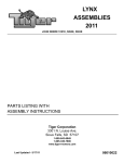
Service Manual
Section 2 ESR750 & ESR750Ex
SECTION 2: ESR 750 ELECTRIC MODEL
This section contains parts illustrations, parts lists, as well as troubleshooting information for
the Electric Go-Ped® models, ESR750, ESR750Ex and their motor.
Paragraph
Page
2.1
ESR750 & ESR750Ex Motor Service............................................................................ 2-1
2.2
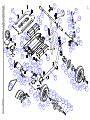
ESR750 & ESR750 Ex Parts Illustration ....................................................................... 2-7
2.3
ESR750 and Batterty Upgrade Kit Parts Illustration...................................................... 2-8
2.4
ESR seat attachment Parts Illustration ........................................................................... 2-8
2.5
ESR accessories.............................................................................................................. 2-9
2.6
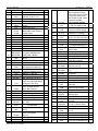
ESR Parts lists ............................................................................................................. 2-10
2.7
ESR troubleshooting guide........................................................................................... 2-12
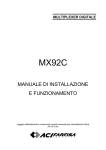
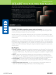
2.1. ESR750 & ESR750Ex Motor Service
The ESR750 motor is a brush DC motor. It consists of a Field (steel tube and magnets) an
Armature (rotating portion) and Comm End (brush assembly and finned heat sink).
Figure #1 shows the major motor components disassembled.
Figure 1
2-1
Service Manual
Section 2 ESR750 & ESR750Ex
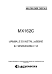
To remove the motor from the ESR frame first turn off the ON/OFF switch, then disconnect
the motor wires from the Comm End shown in Figure #2.
You will need to pull back the rubber boots and remove the two outer ¼-20 nuts. Do NOT
remove the two inner nuts which are behind the two terminal rings.
Next, disconnect the small plastic two-wire connector which is for the motor thermostat. The
connector has a locking tab which can easily be released with a small flat head screwdriver or
even a small zip tie.
Figure 2
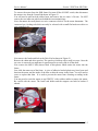
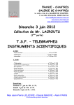
Next remove the fender and look at the Drive End as shown in Figure #3.
Remove the chain and drive sprocket. The sprocket is held on with a small set screw. Once the
set screw is removed you might need a sprocket puller to easily slide it off the shaft.
Now remove the M6x35 bolt (shown black in this photo) which retains the motor into the
frame.
Last, slide the motor out of the frame. A piece of adhesive-backed plastic may have been used
between the motor and the inside of the tube to shim the motor in the frame. You will need to
reuse or replace that shim. It is used to prevent the motor from vibrating or rattling in the
frame.
You may need to twist the motor or tap GENTLY with a rubber mallet to remove the motor.
Be careful with the motor. The brush card holder and the magnets can both be broken if
abused.
Figure 3
2-2
Service Manual
Section 2 ESR750 & ESR750Ex
Once the motor is removed, you should scribe lines on the motor field and the motor end caps
for easy reassembly. On the bottom of the motor simply scribe small marks across the joint
between each end cap and the motor Field. Those marks will help you re-align the rotation of
the end caps during re-assembly. Proper alignment is important for good motor performance.
If the end caps are improperly twisted the motor will run less efficiently.
Now you are ready to open the motor up. Looking again at Figure #3 you will see two small
hex nuts which are part of the motor. Remove those nuts and the lock washers behind them.
Now you can pull the motor apart into three parts as shown in Figure #1. You might need to
tap GENTLY on the finned Comm End to separate it from the Motor Field.
When you separate the motor the brushes will be pushed out of the holder by the four brush
springs. Be careful not to lose the springs.
Figure 4
Inspect the armature. The epoxy which is orange in this photo will probably be much darker in
color. This is a normal effect caused by brush dust. Inspect the face of the commutator for any
bad segments. The segments are the pie-shaped copper portions of the commutator. A bad
segment will look much different than the rest of the commutator. It will be blackened or
discolored. That is indicative of a broken connection in the winding.
Also check the bearing which is in the billet aluminum Drive End plate.
Figure 5
2-3
Service Manual
Brush Spring
Section 2 ESR750 & ESR750Ex
Brushes
Brush Holder
Now inspect the Comm End (Figure 5). The four brushes should have been pushed up and
possibly out of the brush holder by the four springs. Make sure the brushes are moving freely
and are not stuck in the holder.
Inspect the brushes. When new they are ½” tall. If the brushes are less than .225” tall, they
should be replaced. Brush life will probably be at least 750 hours of use.
Inspect the brush holder for cracks or signs of overheating or deformation.
If necessary, disassemble the Comm End.
First turn the Comm End over to the finned side and remove the two ¼-20 flanged nuts from
the terminal studs. Remove and save the two black plastic flanged washers which are below
the nuts.
Next turn the comm end back over and remove the two Philips Head screws from the brush
holder. Be sure to save the washers, and remember their locations. The Comm End is now
fully disassembled. Note the location and routing of the brushes and wires before removing
them!
FYI - The small electrical component epoxied into the end cap is the thermostat. It should not
be removed.
Comm End Reassembly:
- Place the brush holder into the end cap.
- Place the brushes in their holders the way you found them, and place the terminal studs
through the holes in the end cap. If you install the brushes wrong the motor may run in reverse
or not at all. *Don’t install the brush springs yet.
- Hold the parts in place with your hand and flip the end cap over. Install the two black plastic
flanged washers, and then install the two ¼-20 flanged nuts. That will hold the brushes and
brush holder in place. Tighten the nuts to 20-25 in-lbs. Over tightening can break the brush
holder.
- Flip the comm end back over. Reinstall the Philips head screws and washers the way you
found them. Torque the screws to 20-25 in-lbs. It is very important that the wires be routed
correctly. Where the two long brush wires cross, they are retained by the washer under one of
the Philips head screws. Make sure that the white plastic insulating sleeves are correctly
placed to prevent the copper wires from contacting the aluminum end cap. Make sure that the
bushes can freely slide in the holder. If a brush cannot move freely, the motor will fail after a
small amount of use!
2-4
Service Manual
Section 2 ESR750 & ESR750Ex
>>As the motor spins the commutator gradually wears down the brushes. The brush
springs insure that the brushes stay in constant contact with the commutator. If a brush
becomes stuck, it will gradually lose contact with the face and electricity will begin
arcing to the commutator. This will gradually degrade the commutator. It will also
cause overheating which could damage the brushes, the wires, or the brush holder.
When a stuck brush occurs the rider will feel his power diminish to about 50% of
normal as the motor begins to malfunction.
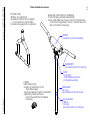
- When you are ready to reassemble the motor you can reinstall the brush springs. It can be
difficult to hold the brushes in place while you assemble the motor. Using the drawing below
you can make a simple tool to make this task easier. Simply cut the shape out of a rigid metal
or plastic sheet perhaps 1/8” thick. Make sure you clean the tool off thoroughly so that no
particles are left behind in the motor.
Figure 6 & 7
Motor Reassembly:
- With the Comm End reassembled, drop the four brush springs into the holder, and then push
the brushes down on top of the springs. Use the tool described above (or something similar) to
hold the brushes in place as shown in Figure #6.
2-5
Service Manual
Section 2 ESR750 & ESR750Ex
- Put the Armature through the Field, and place them both down onto the Comm End as shown
in Figure #7. Make sure that you have both end oriented correctly. Use the marks you scribed
across the Field and End Caps to realign the ends with the Field.
- Pull the tool out, and allow the field to drop all the way down onto the Comm End.
*You may need to help guide the two long threaded-rods through the holes on the Drive End.
You may also need to help align the end of the armature into the bronze bushing in the Comm
end.
- Once the three sections are assembled, recheck your rotation to make sure your scribed marks
are aligned. Then install the lock washers and nuts. Torque to 25-39 in-lbs.
Turn the output shaft and make sure the motor spins. There will be drag from the magnets, but
you should be able to turn the shaft by hand.
Motor Reinstallation:
- Reinstall the motor in the scooter frame. Reinstall the plastic shim between the motor and the
inside of the frame tube to keep the motor from vibrating in the frame.
- Install the M6x35 socket head bolt, which both mounts the chain tensioner AND retains the
motor in the frame. Torque to 8 ft-lbs. The original bolt has a locking nylon patch, which is
only good for one or two installations. If the patch is worn out, use a new bolt or Blue Loctite.
- Reinstall the sprocket and chain. You might need to clean up the end of the motor shaft to
allow the sprocket to easily reinstall. Sandpaper or a file can quickly accomplish this.
- Hook the small plastic 2-wire thermostat connector back together.
- Hook the motor wires back up. Make sure the terminal rings are not left close to the
aluminum end cap, or a short could occur. Torque the two outer ¼-20 nuts to 20-25 in-lbs.
Overtightening could break the brush holder! Those nuts have a nylon locking insert which
can only be reused a couple of times. If the nuts are not locking properly, replace them with
new ones!
- With the rear wheel OFF THE GROUND turn on the scooter and apply the throttle. Make
sure the rear wheel is spinning the correct direction. If it is spinning backwards, reverse the
two motor wires.
-Reinstall the rubber boots over the terminals.
-Reinstall the fender.
Motor Testing:
You can test the motor in the following way:
-With the motor installed in a scooter remove the chain.
-Either hook up a Go-prammer to the scooter, or place a clamp type amperage probe over one
of the two motor wires (but not both wires!) You may need to remove the deck to install the
clamp probe.
-If using the Go-prammer, use the instruction manual to switch to the “CURRENT” parameter
under the Debug Menu.
-Run the motor at full throttle with no load and measure the amperage draw. It should be less
than 4.2amps. If you are using the Go-prammer to measure current, use the chart in the
instruction manual to translate the reading on the screen into amperage.
2-6
2-7
2-8
! " #$
% !%
("
) " *" +
&
#$
'
'
2-9
.
!"
&
#
% #
$%"
(
'
/#&
#
(&
$%" # !
-&
/
% (
!
0
&
&
!
**14
# !
)%" **1
2
&# &#
*
#(
3
#(
*
%
7&
#(
#
7
7
7-
%
#&
&
-
#
&# &#
# !
#
#( #
8
)%" *+,
*
-
5
*+
6
-
Service Manual
Item
-
Part #
-
4
5
6
1028
1028N
1028B
7
8
9
10
11
15
16
17
-
1028C
1411
6109,
6110A,
6110B
1049
1048L
GSR1041
1060
1022
-
19
MD1027CR
MD1027BK
20
21
-
1090
1083A
-
23
6128
24
25
27
GSR1035
1076
BF1033
28
6114
29
33
38
E1006
KN1009
1026
39
BF1036
40
6133
41
1401
42
43
44
TB1028
6102
6800
Section 2.2 – ESR750
Description
Front fork bearing kit, 2
bearings, 2 cups, 1 nut
Head set; Fork nut
Head set; bearing (single)
Head set; Bearing cup
(single)
Carry Loop, nylon
ESR Throttle Lever, See
identification chart to select
correct model
Grip Set
Brake Lever (Left)
T-bar anodized, 24.75”
Safety Spring
Slide Tube Assmbly
Front Fork, single sided,
10” wheel, Maddog brake,
Candy Red or BlacK
Bolt; Maddog Brake Mount;
M6x12
Maddog Brake Caliper
Kickstand; complete; black
with spring and rubber foot
Bolt; ¼-20 x 1.5” Button
Head for kickstand mount
Washer, ¼” SAE flat
Bolt; front axle; 5/8-18 x 6"
Bolt; deck mount; 1/4-20 x
1-3/4 Torx Flat Head thread
cutting (tool size T30)
Deck, with grip tape and
foam, (ESR750 & ESR
Sport, Not EX deck)
Nut; 1/4-20 Nylock
Nut, M6 low nylock
Washer; axle; 1"OD x 5/8"
ID x .060"
Bolt; motor mount; M6x18
Socket head
Bolt; motor mount; M6x35
SHCS
Steel Tube, inserts into
plastic chain guide,
3/8”x.78”
Chain guide, plastic
Electric Motor
Revised on 11/3/2005
Qty
0
1
2
2
1
1
1
1
1
1
1
-
1
2
1
1
2
3
1
4
1
4
1
2
1
1
1
1
1
45
6113A
46
6115
47
6148
48
6118A
49
50
51
6013
6108A
6136
52
6016
53
54
55
57
-
6015
6008
2001
ESR1001CR
ESR1001BK
-
60
BF1038B
61
BF1038A
62
63
64
-
2026M
BF1058T
BF1059O
-
66
1087
67
68
1088
8008
69
70
8003SS
BF1037
71
6127
72
73
GSR1045
GSR1014
74
75
76
-
6006
6009.15
GSR1013.1
-
78
6003
Controller board (left side of
pan, with attached wires)
**This is the current version
of controller which works
with Throttle 6110B. Older
controllers available.
Ask Customer Service.
Screw; controller mount;
6 x 5/8" Hex washer head
Wire; DC interconnect;
Controller to NEW charger
Charger (New style with
aluminum “U” housing)
Screw; Charger Mount;
10-32 x 5/16 hex wshr head
A/C Inlet; (for new charger)
Pop rivet; for A/C Inlet
Bolt; fender mount; 10-32 x
½” Philips Head (type F)
Bolt; fender mount; M4x12
Socket Head
Fender; rear; ESR750 &EX
Deck Grip Tape Set
Frame, ESR750
Candy Red or BlacK
Spacer, wheel bearing,
Mag Rim (10" PT)
Bearing; Mag Wheel; 10"
(PT)
Wheel; 10"PT, 2pcs.
Magnesium
Inner Tube; 10"PT
Tire; no tube, Powerplay TT
Spacer; front wheel to
brake disk
Bolt 3/8-24 x 3.5" Low hex
head; front wheel assy
Nut; 3/8-24 center lock
Brake Disc, hardened
stainless steel
Nut; axle, 5/8-18 nylock
Spacer; rear axle, stepped
for fender
Bolt; Rear wheel assembly;
3/8"-24 x 3" Button Head
Spacer; Wheel to sprocket
Set screw for sprocket;
M5 x 8
Sprocket, 15 tooth, #25
Sprocket; 76 tooth (alum)
Rubber Plug; installs into
rear of pan; holds data plug
1
4
1
1
4
1
2
1
1
1
1
1
2
4
2
2
2
4
4
8
2
2
1
4
4
1
1
1
1
2-10
Service Manual
79
6107R
6107
80
6120C
81
6131
82
6121
83
6119C
84
6005
85
87
-
6126
1404
-
100
1043
101
1044
102
1043A
103
104
-
1045
1056
-
106
6103
Section 2.2 – ESR750
Battery Pan; ESR750 and
EX, not Sport. Red or Black
Foam Pad; 1/8” thick
installs under batteries
Rubber pan dust shield.
Square 2”x2” w/ center hole
Plastic insulation tape;
white; prevents short
between pan & batteries
Foam Rubber Tape; 1/4"x
1/2"; sold per ft.
Also used on deck.
Battery; HR6-12 T2 SLA
(ESR750 & Sport, Not EX)
Battery connector; Joins
each pair of batteries. Old
style was 4” long wire. Now
a small metal tab is used.
Bolt; rear axle 5/8-18 x 7.5"
Lower hinge FTG. assy;
Aluminum
Bolt; lower hinge FTG.
5/16-24
Lower hinge FTG; clear
anodized aluminum
Wedge lug; lower hinge
FTG.
Handle hinge pin
Chain; #25 Hard, 106 link
(ESR750 & EX; not Sport)
1
2
4
2
88”
4
6005B
1006ES
E1006F
111
114
115
116
6114B
9004
1094
1095
ESR9002BK
ESR9002CR
6305
1097
7025
6119
117
118
119
120
121
Battery; HR9-12 T2 (larger
battery; EX and upgrade)
Deck Spacer; 1” thick wood
Deck; no grip tape; ¼” thick
Bolt; deck mount; 1/4-20 x
2-1/4 Torx Flat Head thread
cutting (tool size T30)
Seat with hardware
Seat post; aluminum
Seat post collar
Seat frame,
Black or Candy Red
Neoprene rubber foot
Bolt; 5/16-24 x 1.5 SHCS
Nut; 5/16-24 nylock
Toe Guard; black
Revised on 11/3/2005
1081
1063
1064
1061
1053
1053S
1065
1068
6002
6010
2
1
-
6011
6012
6022
6033
1
6108
1
1
6110
1
1
-
6116
1
THE FOLLOWING ITEMS ARE ON PAGE 2-15
108
109
110
ITEMS NOT SHOWN ON PARTS ILLUSTRATION
4
1
1
6118
6129
6160
9031
GSR1055
Brake Cable, 38"H / 48"C
Yellow Warning Sticker
Red Warning Sticker
Sticker; Reflective T-Bar
pad
Large Zip Tie (black; 8")
Small Zip Tie (black; 4")
Sticker; www.goped.com
Sticker; made in USA
A/C power cord, 72”
Sticker; Goped decal,
metallic; for side of pan
Sticker; ESR750 (installs
on tail of frame)
Sticker; Chrome Decal
(ESR750) for slide tube
Heat Shrink tubing for
throttle wire connection
Sticker; “CE” for europe
Old A/C inlet. Used on early
ESRs with Old charger.
Old On/Off Switch. Used on
early ESRs, placed on left
side of T-bar.
Old Charger LED board.
Used on early ESRs.
Installed between Old
charger and controller
Old Charger. Used on early
ESRs. This charger does
not have “U” shaped
aluminum housing
Sticker; “HOT” for motor
White/Red warning sticker
User Manual (ESR)
Sticker; Goped (Installs on
fender)
1
1
1
1
1
2
1
1
1
2
1
1
1
1
0
0
0
0
1
1
1
1
4
1
1
1
1
1
1
1
1
2-11
Service Manual
Section 2 ESR750 & ESR750Ex
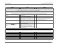
Problem
Acceleration and hill climbing greatly reduced
from when scooter was new. Change was rapid
and power loss may be %50.
Range is extremely low. May have reduced
suddenly from one trip to the next.
Motor is making noise, but scooter will not move
or operates intermittently
Action
Disconnect chain from motor. Use an amp meter to
measure amp draw at full throttle, and no load, at a
full charge. Draw should not exceed 4.2amps.
1 A motor malfunction could cause abnormally high
current draw. Use amp meter to measure draw as
described above.
2 A battery wire could have become disconnected,
causing the scooter to run on only 2 batteries instead
of 4.
3 Batteries could be old and need replacement. In this
case the range degradation would be gradual, not
immediate.
Check drive sprocket set screw. If the screw has
loosened up, it could be slipping on the motor shaft.
This problem is sometimes be misdiagnosed as
electrical.
Solution
If draw exceeds 4.2amps, motor is malfunctioning.
If draw exceeds 4.2amps, motor is malfunctioning.
Open Pan and inspect for disconnected battery wires.
Replace batteries.
Put drop of Blue Loctite on set screw and re-tighten.
Deck Removal:
While working on an ESR you might find it necessary to remove the deck. The first several hundred ESRs which were produced have had the decks sealed to the aluminum pans with
clear silicone. It is pretty easy to remove the deck, but the first time you do it can be a little tricky. First remove the four deck bolts. Now start by running a razor blade all the way
around the scooter in the joint between the wood deck and the aluminum pan. This will begin to cut the silicone. Next take a long flat blade screw driver and start to pry the deck up at
the FRONT of the scooter. (The electronics are all the rear of the scooter.) As you pry the deck up you will be able to see more of the silicone. Cut the silicone with the razor. The
more you cut, the more you'll be able to raise the deck. Gradually work your way around the deck until enough of the silicone it cut for the deck to be removed.
2-12
Service Manual
Section 2 ESR750 & ESR750Ex
Action
Solution
Scooter will not operate
A) Throttle LEDs DO turn on and clicking IS heard
from pan when on/OFF switch IS operated. (The
clicking noise is the relay on the controller board. It
should click when the ON/OFF switch is operated.)
Problem
(1)Check to make sure wires are correctly attached to
motor. (2)Measure voltage at motor wires while
operating throttle. Make sure reading is about 24V at
full throttle.
If 24V is found and wires are properly connected, motor must
be malfunctioning. If 24V is NOT found at motor, then throttle or
controller is malfunctioning.
B) Throttle LEDs do NOT turn on and/or clicking is
NOT heard from pan when on/OFF switch IS
operated.
(1)Check for throttle or ON/OFF switch malfunction.
(2)Open pan and check if power is getting to
controller. Controller should be receiving about 24V.
If problem wasn't found with step 1 or 2, controller may be
malfunctioning.
Faulty throttle suspected.
Disconnect throttle at 8 pin connector, and install new
throttle. If that does not solve the problem, the fault
may be in the controller.
If the controller is suspected, install a known good controller to
see if the problem is solved.
Faulty ON/OFF switch suspected.
Disconnect ON/OFF at 2 pin connector, and install
new ON/OFF If a known good ON/OFF switch isn't
available you can short the two metal pins in the wire
coming from the controller. When the circuit is
completed, the controller should click and turn on. If
that does not solve the problem, the fault may be in
the controller.
Remove deck. Inspect wires to be sure that all
connections are still attached. With meter measure
voltage across each battery. Voltage should be
approximately 12V.
If the controller is suspected, install a known good controller to
see if the problem is solved.
Batteries bad or disconnected.
If connectors are off, reinstall and glue with silicone to insure
that they do not come back off. If batteries are bad, replace the
entire battery pack, not just one cell.
2-13
Service Manual
Section 2 ESR750 & ESR750Ex
Problem
Action
Solution
Charger problems
Background: Power flows from the inlet plug (110V or 220V AC) to the charger. Then 24V DC power flows from the charger to the small LED board. Then 24V DC power flows from
the LED board to the Controller. The power passes through the controller to the batteries. The batteries are wired into two individual 24V battery packs which are in parallel. There are
short connection wires between each set of batteries. If one of those wires is disconnected the scooter WILL run on half the batteries with 50% of normal range. Those connection
wires should have silicone adhering them in place to prevent accidental disconnection.
Testing the charging system: When testing the charging system for proper operation it is a good idea to first disconnect the batteries so that you do not get a false voltage reading from
the batteries. After the batteries are disconnected, you can individually measure the voltage across both sets of battery wires. With the charger plugged in, the voltage to the batteries
should be about 24V. If you do not read approximately 24V going to the batteries, then there is a breakdown somewhere in the system.
A) LED on side of pan will not light when cord
plugged in.
1 The outlet in the wall may be off. Plug in a lamp to
make sure it is live.
2 The A/C cord may be bad. Try using a cord known to
be good, or test the cord with a multimeter.
3 Charger may be malfunctioning. Remove deck, and
with scooter plugged in carefully measure for 24V
output from Charger. (2 wire connector, not 3 wire.)
B) LED goes to green immediately after plugging in
scooter, even though batteries are known to be
discharged.
4 Charger LED board may be malfunctioning. Measure
for 24V output from LED board to controller. It will be
necessary to disconnect the LED board from the
controller to perform this test.
There is probably a disconnection somewhere
between the LED board and the batteries. The LED
board may be disconnected from controller; the
controller may be disconnected from batteries; or the
short wires connecting the batteries may be off. Check
all those connections.
If no 24V output, carefully check 110V A/C wires between
charger and plug receptacle. If no problem found, replace
charger. If 24V present go to next test.
Replace LED board if necessary.
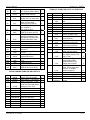
Error Codes
The ESR controller is very advanced and has self-diagnostic features. If the ESR senses a problem it will alert the rider, similar to a "check engine" light in a car. The warning comes in
the form of flashing codes on the Flux Capacitor LEDs. The codes are listed below for your reference. These codes can also be retrieved and reset using the Go-Prammer.
Fault Code
21
22
32
41
42
51
53
62
Problem
Motor Short
Motor Open
Overtemperature
Charger Overvoltage
Charge Mode Time Out
Internal Controller Fault
Throttle Failband
Internal Controller Fault
Possible Cause
Bad motor, shorted connection to motor or controller
Bad motor, Loose/broken connection to motor or controller
Excessive Use, Excessive ambient temperature, or controller
Battery Charger
Probably a bad battery
Controller
Throttle control is malfunctioning, loose/broken cable, controller
Controller
2-14