1
User Manual
AT-140GE
Digital 3CCD Progressive Scan
RGB Color Camera
Document Version:1.0
AT-140GE_Ver.1.0_Jan2011
1013E-1101
AT-140GE
Notice
The material contained in this manual consists of information that is proprietary to JAI Ltd.,
Japan and may only be used by the purchasers of the product. JAI Ltd., Japan makes no
warranty for the use of its product and assumes no responsibility for any errors which may
appear or for damages resulting from the use of the information contained herein. JAI Ltd.,
Japan reserves the right to make changes without notice.
Company and product names mentioned in this manual are trademarks or registered
trademarks of their respective owners.
Warranty
For information about the warranty, please contact your factory representative.
Certifications
CE compliance
As defined by the Directive 2004/108/EC of the European Parliament and of the Council, EMC
(Electromagnetic compatibility), JAI Ltd., Japan declares that AT-140GE complies with the
following provisions applying to its standards.
EN 61000-6-3 (Generic emission standard part 1)
EN 61000-6-2 (immunity)
FCC
This equipment has been tested and found to comply with the limits for a Class B digital
device, pursuant to Part 15 of the FCC Rules. These limits are designed to provide reasonable
protection against harmful interference in a residential installation. This equipment
generates, uses and can radiate radio frequency energy and, if not installed and used in
accordance with the instructions, may cause harmful interference to radio communications.
However, there is no guarantee that interference will not occur in a particular installation. If
this equipment does cause harmful interference to radio or television reception, which can be
determined by turning the equipment off and on, the user is encouraged to try to correct the
interference by one or more of the following measures:
- Reorient or relocate the receiving antenna.
- Increase the separation between the equipment and receiver.
- Connect the equipment into an outlet on a circuit different from that to which the
receiver is connected.
Consult the dealer or an experienced radio/TV technician for help.
Warning
Changes or modifications to this unit not expressly approved by the party responsible for FCC
compliance could void the user’s authority to operate the equipment.
-1-
AT-140GE
Supplement
The following statement is related to the regulation on “ Measures for the Administration
of the control of Pollution by Electronic Information Products “ , known as “ China RoHS “.
The table shows contained Hazardous Substances in this camera.
mark shows that the environment-friendly use period of contained Hazardous
Substances is 15 years.
嶷勣廣吭並㍻
嗤蕎嗤墾麗嵎賜圷殆兆各式根楚燕
功象嶄鯖繁酎慌才忽佚連恢匍何〆窮徨佚連恢瞳麟半陣崙砿尖一隈〇云恢瞳ゞ 嗤蕎嗤
墾麗嵎賜圷殆兆各式根楚燕 〃泌和
桟隠聞喘豚㍉
窮徨佚連恢瞳嶄根嗤議嗤蕎嗤墾麗嵎賜圷殆壓屎械聞喘議訳周和音氏窟伏翌
亶賜融延、窮徨佚連恢瞳喘薩聞喘乎窮徨佚連恢瞳音氏斤桟廠夛撹冢嶷麟半
賜斤児繁附、夏恢夛撹冢嶷鱒墾議豚㍉。
方忖仝15々葎豚㍉15定。
AT-140GE
Table of Contents
JAI GigE® Vision Camera operation manuals ............................................ Introduction ................................................................................... Before using GigE Vision camera .......................................................... Software installation ......................................................................... Camera Operation ............................................................................ 1. General ..................................................................................... 2. Camera nomenclature................................................................... 3. Main Features .............................................................................. 4. Locations and Functions ................................................................. -
6
6
6
6
7
7
7
8
9
-
4.1. Locations and functions .................................................................................. - 9 4.2. Rear panel indicator .................................................................................... - 10 -
5. Pin Assignment ........................................................................... - 11 5.1. 12-pin Multi-connector (DC-IN/Digital IO) ............................................................
5.2. Digital Output Connector for Gigabit Ethernet.....................................................
5.3. D-Sub 9pin connector (For GPIO) ...................................................................
5.4. DIP switch .................................................................................................
5.4.1 SW-600 ..............................................................................................
5.4.2 SW-100 ..............................................................................................
5.4.3 SW-700 ..............................................................................................
- 11
- 11
- 12
- 12
- 12
- 13
- 13
-
6. Input and output Interface .......................................................... - 14 6.1. Digital Interface .........................................................................................
6.1.1 LineSelector ........................................................................................
6.1.2 LineInverter ........................................................................................
6.1.3 LineStatus ...........................................................................................
6.1.4 LineSource ..........................................................................................
6.1.5 LineMode ............................................................................................
6.1.6 LineFormat .........................................................................................
6.2. Opto-isolated Interface ................................................................................
6.2.1 Recommended External Input circuit diagram for customer ..............................
6.2.2 Recommended External Output circuit diagram for customer ............................
6.2.3 Optical Interface Specifications ................................................................
6.3. Iris video output .........................................................................................
6.4. Trigger input .............................................................................................
6.5. Exposure Active output .................................................................................
- 14
- 14
- 14
- 14
- 14
- 14
- 14
- 14
- 15
- 15
- 15
- 16
- 16
- 16
-
7. Video signal output .................................................................... - 17 7.1. Video output image .....................................................................................
7.2. AOI (Area of Interest) ...................................................................................
7.2.1 AOI parameters ...................................................................................
7.2.2 AOI setting details ................................................................................
7.2.2.1 When only the image part is transmitted (OB is not transferred) .....................
7.2.2.2 When the full image plus the vertical OB is transmitted................................
7.2.2. When the full image plus the horizontal OB is transmitted ..............................
7.3. In case of vertical binning and horizontal binning .................................................
7.4. Digital video output (Bit allocation) .................................................................
7.5. Pixel format and pixel type ............................................................................
7.5.1 GVSP_PIX_RGB8_PACKED (RGB 24bit output) ................................................
7.5.2 GVSP_PIX_RGB10V1_PACKED (RGB 30bit output) ............................................
7.5.3 GVSP_PIX_RGB10V2_PACKED (RGB 30bit output) ............................................
7.6. Auto iris video output level ............................................................................
7.7. Video output timing .....................................................................................
7.7.1 Binning Vertical = 1 (OFF) .......................................................................
7.7.1.1 1 frame period ..................................................................................
7.7.1.2 Horizontal period (In case of normal mode, full frame or AOI) ........................
-2-
- 17
- 18
- 18
- 18
- 18
- 18
- 19
- 19
- 19
- 20
- 20
- 20
- 20
- 20
- 21
- 21
- 21
- 22
-
AT-140GE
7.7.2 Binning Vertical =2 (ON) ......................................................................... - 23
7.2.2.1 Vertical period .................................................................................. - 23
7.7.2.2 Horizontal period .............................................................................. - 23
7.8. The calculation of AOI size and frame rate ......................................................... - 24
7.9. The relationship between LinePitch and Width .................................................... - 24
7.10. The relationship between PxelSize and PixelFormat ............................................ - 25
7.11. The relationship between Binning Horizontal and Width/LinePitch .......................... - 25
7.12. The relationship between Binning Vertical and Height ......................................... - 25
-
8. Network configuration ................................................................ - 26 8.1. GigEVision Standard interface ......................................................................... - 26
8.2. Equipment to configure the network system ....................................................... - 26
8.2.1 PC .................................................................................................... - 26
8.2.2 Cables ............................................................................................... - 26
8.2.3 Network card (NIC) ................................................................................ - 26
8.2.4 Hub ................................................................................................... - 27
8.3. Recommended Network Configurations ............................................................. - 27
8.3.1 Guideline for network settings ................................................................. - 27
8.3.2 Video data rate (network bandwidth) ......................................................... - 28
8.3.3 Note for setting packet size ..................................................................... - 28
8.3.4 Calculation of Data Transfer Rate .............................................................. - 28
8.3.5 Simplified calculation (Approximate value) .................................................. - 29
8.3.6 Note for 100BASE-TX connection ............................................................... - 29
8.4. GigE camera connecting examples ................................................................... - 30
8.4.1 Using a switching hub for 1 port ................................................................ - 30
8.4.2 Connecting a camera to each port of a multi-port NIC ..................................... - 30
8.4.3 The data transfer for multiple cameras ....................................................... - 31
8.4.3.1 If delayed readout is not used in continuous mode ...................................... - 31
8.4.3.2 If delayed readout is not used in trigger mode ........................................... - 31
8.4.3.3 If delayed readout is used .................................................................... - 32
-
9. Core functions ............................................................................ - 33 9.1. Acquisition function ..................................................................................... - 33
9.1.1 Basic image acquisition flow .................................................................... - 33
9.1.2 Acquisition mode .................................................................................. - 34
9.1.2.1 Single Frame .................................................................................... - 34
9.1.2.2 MultiFrame ...................................................................................... - 35
9.1.2.3 Continuous mode ............................................................................... - 36
9.1.3 AcquisitionAbort ................................................................................... - 37
9.1.4 AcquisitionFrameCount ........................................................................... - 37
9.1.5 AcquisitionFrameRate ............................................................................ - 37
9.1.5.1 Setting the self running mode (Trigger OFF) .............................................. - 38
9.1.5.2 The calculation of the frame rate for the setting area.................................. - 38
9.1.6 AcquisitionStatus .................................................................................. - 39
9.2. Trigger Control ........................................................................................... - 40
9.2.1 TriggerSelector(TriggerMode) ................................................................... - 40
9.2.1.1 Acquisition ....................................................................................... - 40
9.2.1.2 Exposure ......................................................................................... - 41
9.2.2 Memory readout control ......................................................................... - 42
9.2.3 Triggersoftware .................................................................................... - 42
9.2.4 Triggersource ...................................................................................... - 42
9.2.5 TriggerActivation .................................................................................. - 43
9.2.6 Triggeroverlap ..................................................................................... - 43
9.2.7 Triggerdelay ........................................................................................ - 43
9.3. Exposure Control ........................................................................................ - 43
9.3.1 Exposure Mode ..................................................................................... - 43
9.3.2 ExposureTime ...................................................................................... - 44
9.3.3 ExposureAuto ....................................................................................... - 45
-3-
-
AT-140GE
9.4. UserOutputSelector .....................................................................................
9.5. Counter function.........................................................................................
9.5.1 CounterSelector ...................................................................................
9.5.2 CounterEventSource ..............................................................................
9.5.3 CounterEventActivation ..........................................................................
9.5.4 CounterResetSource ..............................................................................
9.5.5 CounterResetActivation ..........................................................................
9.5.6 CounterValue .......................................................................................
9.5.7 CounterValueAtReset .............................................................................
9.5.8 CounterDuration ...................................................................................
9.5.9 CounterStatus ......................................................................................
9.5.10 CounterTriggerSource ............................................................................
9.5.11 CounterTriggerActivation .......................................................................
9.6. Timer Control ............................................................................................
9.6.1 TimerSelector ......................................................................................
9.6.2 TimerDuration .....................................................................................
9.6.3 TimerDelay .........................................................................................
9.6.4 TimerValue .........................................................................................
9.6.5 TimerStatus ........................................................................................
9.6.6 TimerTriggerSource ...............................................................................
9.6.7 TimerTriggerActivation ...........................................................................
9.7. Event Control .............................................................................................
9.7.1 EventSelector ......................................................................................
9.8. Video Send Mode ........................................................................................
9.9. ActionControl.............................................................................................
- 45
- 45
- 45
- 45
- 46
- 46
- 46
- 46
- 46
- 46
- 46
- 47
- 47
- 48
- 48
- 48
- 48
- 48
- 48
- 48
- 49
- 49
- 49
- 49
- 49
-
10. Operation modes...................................................................... - 50 10.1. Continuous mode (Free run) .........................................................................
10.2. Trigger operation with “timed” exposure (Previously called EPS) ............................
10.3. Trigger operation by “TriggerWidth” (Previously called PWC) ................................
10.4. Trigger operation by TriggerControlled ............................................................
10.5. Trigger input and exposure start timing ...........................................................
10.5.1 Synchronous reset timing .......................................................................
10.5.1.1 In the case of Expsoure mode = Timed, Trigger = ON (Full frame) ..................
10.5.1.2 In the case of Expsoure mode = Trigger width, Trigger = ON (Full frame) .........
10.5.2 Asynchronous reset timing .....................................................................
10.5.2.1 In the case of Expsoure mode = Timed, Trigger = ON (Full frame) ..................
10.5.2.2 In the case of Expsoure mode = Trigger width, Trigger = ON (Full frame) .........
10.6. Sequence Trigger Mode ...............................................................................
10.7. Multi ROI Mode .........................................................................................
10.8. Delayed Readout Mode (JAI Custom Control) .....................................................
10.9. Mode and function matrix table .....................................................................
- 50
- 50
- 51
- 52
- 53
- 53
- 53
- 53
- 54
- 54
- 54
- 55
- 56
- 57
- 57
-
11. Image processing ...................................................................... - 58 11.1. Basic construction .....................................................................................
11.2. Shading compensation ................................................................................
11.3. Auto White balance ....................................................................................
11.4. Gain ......................................................................................................
11.4.1 GainAuto ...........................................................................................
11.5. BlackLevel ...............................................................................................
11.6. Linear matrix ...........................................................................................
11.7. Blemish compensation ................................................................................
11.8. LUT (Look Up Table) and gamma ....................................................................
11.9. Test pattern generator ................................................................................
- 58
- 58
- 59
- 59
- 60
- 60
- 60
- 60
- 61
- 61
-
12. Examples of operation using JAI Control Tool .................................. - 62 12.1. About GenICamTM SFNC1.3............................................................................ - 62 12.2. JAI SDK Ver.1.3 ......................................................................................... - 62 12.3. Examples of camera operation ...................................................................... - 63 -
-4-
AT-140GE
12.3.1 Operational cautions ............................................................................. - 63 12.3.2 Connecting camera(s) ........................................................................... - 63 12.4. Input and output settings ............................................................................. - 65 12.4.1. Connection with the external devices ...................................................... - 65 12.4.2. Setting inputs and outputs .................................................................... - 65 12.4.2.1 Select signal to connect with Line which is selected by Line selector .............. - 65 12.4.2.2 Select Trigger Source ........................................................................ - 66 12.4.3. Specify the image size to be captured ...................................................... - 67 12.4.4. Acquisition of the image ....................................................................... - 69 12.4.4.1 Basic settings .................................................................................. - 70 12.4.5. Setting examples ................................................................................ - 72 12.4.5.1 Capture the image continuously with fastest frame rate ............................. - 72 12.4.5.2 Capture the image with a half of the frame rate (increasing the sensitivity) ..... - 72 12.4.5.3 Capture one frame of the image with preset exposure time using the external .. - 72 12.4.5.4 Capture multi frames of the image with preset exposure time using the external
trigger ........................................................................................... - 73 12.4.5.5 Capture one frame of the image with the trigger width using the external ....... - 73 trigger ........................................................................................... - 73 12.4.5.6 Capture multi frames of the image with the trigger width using the external .... - 74 trigger ........................................................................................... - 74 12.4.5.7 Capture the image continuously with preset exposure time by using the external- 74 trigger ........................................................................................... - 74 12.4.5.8 Capture the image by Exposure Start trigger and stop by Exposure End. .......... - 75 12.4.5.9 Capture the image using Software Trigger ............................................... - 76 12.4.5.10 Sequence Trigger setting ................................................................... - 76 12.4.5.11 Multi ROI setting ............................................................................. - 77 12.4.5.12 Delayed readout setting .................................................................... - 78 12.4.5.13 Operate the external strobe light ........................................................ - 78 12.4.5.14 Achieve white balance using individual exposure time for R,G,B .................. - 78 12.4.6 How to view the XML file ....................................................................... - 79 -
13. External Appearance and Dimensions ............................................ - 80 14. Specifications ........................................................................... - 81 14.1. Camera sensitivity response.......................................................................... - 81 14.2. Specification table ..................................................................................... - 82 -
Appendix ...................................................................................... - 84 1.
2.
3.
4.
5.
6.
Precautions .................................................................................................. - 84
Typical Sensor Characteristics ........................................................................... - 84
Caution when mounting a lens on the camera ........................................................ - 84
Caution when mounting the camera .................................................................... - 85
Exportation .................................................................................................. - 85
References .................................................................................................. - 85
-
Change history ............................................................................... - 86 User's Record ................................................................................ - 87 -
-5-
AT-140GE
JAI GigE® Vision Camera operation manuals
To understand and operate this JAI GigE® Vision camera properly, JAI provides the following
manuals.
User’s manual (this booklet)
JAI SDK & Control Tool User Guide
JAI SDK Getting Started Guide
Describes functions and operation of the hardware
Describes functions and operation of the Control Tool
Describes the network interface
User’s manual is available at www.jai.com
JAI SDK & Control Tool User Guide and JAI SDK Getting Started Guide are provided with the
JAI SDK which is available at www.jai.com.
Introduction
GigE Vision is the new standard interface using Gigabit Ethernet for machine vision
applications and it was mainly set up by AIA (Automated Imaging Association) members. GigE
Vision is capable of transmitting large amounts of uncompressed image data through an
inexpensive general purpose LAN cable for a long distance.
GigE Vision also supports the GenICamTM standard which is mainly set up by the EMVA
(European Machine Vision Association). The purpose of the GenICam standard is to provide a
common program interface for various machine vision cameras. By using GenICam, cameras
from different manufactures can seamlessly connect in one platform.
For details about the GigE Vision standard, please visit the AIA web site,
www.machinevisiononline.org and for GenICam, the EMVA web site, www.genicam.org.
JAI GigE Vision cameras comply with both the GigE Vision standard and the GenICam standard.
Before using GigE Vision camera
All software products described in this manual pertain to the proper use of JAI GigE Vision
cameras. Product names mentioned in this manual are used only for the explanation of
operation. Registered trademarks or trademarks belong to their manufacturers.
To use the JAI SDK, it is necessary to accept the “Software license agreement” first.
This manual describes necessary equipment and the details of camera functions.
Software installation
The JAI GigE Vision SDK & Control Tool can be downloaded from the JAI web site at
www.jai.com. The JAI SDK is available for Windows XP and Vista, 32-bit and 64-bit.
For the details of software installation, please refer to the “Getting Started Guide” supplied
on the JAI SDK download page.
-6-
AT-140GE
Camera Operation
1. General
The AT-140GE complies with GenICam Standard Feature Naming Convention (SFNC) ver.1.3
and functions described in this booklet are described based on this standard.
The AT-140GE is a digital 3CCD progressive scan RGB color camera. It employs three 1/2-inch
1392 (h) x 1040 (v), 1.45 Megapixel CCDs and runs at 20 frames per second in full resolution
mode. The AT-140GE has a GigE Vision interface and its output can be either 24-bit or 30-bit
RGB. JAI developed a new 1/2-inch compact F4.0 prism optical system and in combination
with a linear color matrix, the AT-140GE provides a higher fidelity of color reproduction. The
AT-140GE also incorporates a dynamic shading circuit, gamma correction circuit and knee
correction circuit to provide high picture quality. Functions like AOI and vertical binning allow
higher frame rates.
The latest version of this manual can be downloaded from: www.jai.com
The latest version of the JAI GigE Vision SDK & Control Tool for the AT-140GE can be
downloaded from: www.jai.com
For camera revision history, please contact your local JAI distributor.
2. Camera nomenclature
The standard camera composition consists of the camera main body and C-mount protection
cap.
The camera is available in the following versions:
AT-140GE
Where A stands for "Advanced" family, T stands for "3 CCD", 140 represents the resolution "1.4
million pixels" , and GE stands for "GigE Vision " interface.
-7-
AT-140GE
3. Main Features
3 x 1/2" CCD progressive scan RGB color camera for vision applications
3 x 1392(h) x 1040 (v) resolution with 4.65m effective square pixels
Compact RGB prism for C-mount lenses
Shading reduction permits wider choice of lenses
Maximum 20.814 frames per second with 1392 (h) x 1040 (v) pixels
Variable partial scan is available for faster frame rate
Maximum 59.94 fps with 1392 (h) x 8 (v) pixels in AOI mode
Vertical binning for higher sensitivity and frame rate of 32.92 fps
Horizontal binning is also available for increasing sensitivity (frame rate is not
changed)
24-bit RGB output or 30-bit RGB output (RGB 8, RGB 10V1 or RGB 10V2 pixel format)
Gamma can be set from 1.0 (OFF) to 0.45 and LUT is also available (selectable)
Linear matrix circuit with sRGB or Adobe RGB pre-setting
Built-in shading compensation circuit for color shading and flat field shading
Blemish compensation ON/OFF function (blemishes are compensated up to 16
pixels)
Acquisition control includes single frame, multi frame and continuous
Exposure mode includes off, timed, trigger width and trigger controlled
Trigger control includes frame start, exposure start and exposure end.
Combination of Acquisition Control, Exposure Mode and Trigger Control provide
various image capture options
Manual, continuous, or one push white balance
Analog iris video output for lens iris control
LVAL synchronous/asynchronous operation (Trigger Overlap function)
Comprehensive software tools and SDK for Windows XP/Vista/7 (32 bit “x86” and 64
bit “x64” JAI SDK Ver. 1.3.0 and after )
-8-
AT-140GE
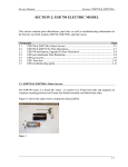
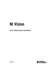
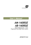
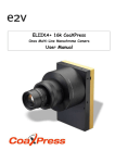
4. Locations and Functions
4.1. Locations and functions
1. Lens mount
2. CCD sensor
3. RJ-45 connector
4. 12-pin connector
5. D-sub 9-pin connector
6. LED
7. LINK
8. ACT
9.Holes for RJ-45 thumbscrews
10.Mounting holes
*1) Note:
*2) Note:
*3) Note:
Lens mount of C-mount type. *1)
1/2 inch CCD
GigE Vision interface with thumb screws
DC+12V, Trigger IN and EEN out
LVDS IN and TTL IN and OUT
Power and trigger indications
Indication for Network connection
Indication for GigE communication
Vertical type and horizontal type (*2)
M3, max length 5mm (*3)
Applicable C-mount lens should be designed for 3-CCD cameras.
Rear protrusion on
C-mount lens must be less than 4mm.
Be advised: when using a lens with the iris diaphragm fully open, vignetting on corners
may occur.
When an RJ-45 cable with thumb screws is connected to the camera, please do not
excessively tighten screws by using a driver. The RJ-45 receptacle on the camera might
be damaged. For security, the strength to tighten screws is less than 0.147 Newton
meter (Nm). Tightening by hand is sufficient in order to achieve this.
The tripod adapter plate MP-41 can be used.
Fig. 1. Locations
-9-
AT-140GE
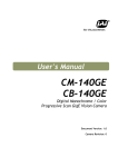
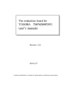
4.2. Rear panel indicator
The rear panel mounted LED provides the following information:
Amber
: Power connected - initiating
Steady green : Camera is operating in Continuous mode
Flashing green : The camera is receiving external trigger
Ethernet connector indicates,
Steady green : 1000 Base-T has been connected
Flashing green : 100 Base-TX has been connected (Note)
Flashing amber : Network active in communication
Note: When 10BASE-T is connected, the green is also flashing.
However, the video is not streamed through Ethernet.
Fig.2 Rear Panel
- 10 -
AT-140GE
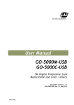
5. Pin Assignment
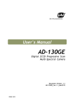
5.1. 12-pin Multi-connector (DC-IN/Digital IO)
Type: HR10A-10R-12PB-01
(Hirose) male.
(Seen from rear of
camera.)
9
1
2
8
10
11
3
4
7
12
5
6
Fig. 3. 12-pin connector.
Pin no.
Signal
Remarks
1
GND
+12V to +24V
2
DC input
3
Opt In 2(-) / GND (*1)
Line 6
4
Opt In 2 (+) / Iris video(*1)
5
Opt In 1 (-)
Line 5
6
Opt In 1 (+)
7
Opt Out 1 (-)Line 3
8
Opt Out 1 (+)
9
Opt Out 2 (-)
Line 4
10
Opt Out 2 (+)
+12V to +24V
11
DC input
12
GND
*1) Default is Opt In 2. DIP switch SW700 changes to
iris video output.
5.2. Digital Output Connector for Gigabit Ethernet
Type: RJ-45
HFJ11-1G02E-L21RL or equivalent
The AT-140GE cameras also accept industrial RJ-45 connectors with
thumbscrews. This assures that the connector does not come undone
in tough industrial environments.
Please contact the nearest JAI distributor for details on
recommended industrial RJ-45 connectors.
Fig. 4. Gigabit Ethernet connector
The digital output signals follow the Gigabit Ethernet interface using RJ-45 conforming
connector. The following is the pin assignment for the Gigabit Ethernet connector.
Pin No
1
2
3
4
5
6
7
8
In/Out
In/Out
In/Out
In/Out
In/Out
In/Out
In/Out
In/Out
In/Out
Name
MX1+ (DA+)
MX1- (DA-)
MX2+ (DB+)
MX3+ (DC+)
MX3- (DC-)
MX2- (DB-)
MX4+ (DD+)
MX4- (DD-)
- 11 -
AT-140GE
5.3. D-Sub 9pin connector (For GPIO)
Type : DD-09SSG
Fig. 5.D Sub
No
1
2
I/O
I
I
3
I
TTL IN 1
4
5
6
7
8
9
O
TTL Out 1
GND
NC
NC
TTL OUT 2
GND
O
Note1)
9pin connector
Name
Note
LVDS In 1LVDS In 1+
Line 8
Line 7
75ohm Terminator (Note 1)
Line 1
Line 2
Can be changed by DIP switch (SW600).
5.4. DIP switch
DIP switches are located on circuit boards. When the top cover is removed, please pay careful
attention so that circuit boards are not damaged.
5.4.1 SW-600
This switch sets the 75 ohm trigger input termination to ON or OFF.
The factory default setting is OFF which is TTL level.
No
1
2
Setting
Functions
Trigger input termination
NC
ON
75Ω
Right side for
75 ohms
termination
ON
ON
SW600
Fig.6. SW600 (On rear panel)
- 12 -
OFF
TTL
AT-140GE
5.4.2 SW-100
This switch selects the ExposureActive signal. The factory default setting is TTL signal and it
can be changed to the open collector signal.
Setting
No
Function
ON
OFF
Exposure Active output
Open Collector
TTL signal
1
select
signal
2
NC
-
ON
Fig.7 SW100 (the right board when looking from the lens side)
5.4.3 SW-700
This DIP switch can select OPT IN or Iris video output through pin#3 and #4 of the
HIROSE 12 pin connector.
The default setting is OPT IN.
Setting
No
Functions
ON
OFF
OPT IN(+) / Iris video OUT
1
Iris video
OPT IN (+)
select
OPT IN(-) / Iris video OUT
2
GND for iris video
OPT IN (-)
select
ON
Fig.8 SW700 (On the top board)
- 13 -
AT-140GE
6. Input and output Interface
6.1. Digital Interface
In the AT-140GE, the input and output interfaces for Hirose 12P and D-Sub 9P are
configured as follows.
6.1.1 LineSelector
The following input and output signals are configured on Line 1 through Line 8.
① Line 1(TTL out1)
② Line 2(TTL out2)
③ Line 3(Opt out1)
④ Line 4(Opt out2)
⑤ Line 5(Opt in1)
⑥ Line 6(Opt in2)
⑦ Line 7(TTL in1)
⑧ Line 8(LVDS in)
6.1.2 LineInverter
This function changes the polarity of the signal.
6.1.3 LineStatus
The user can ascertain the status of input and output signals.
6.1.4 LineSource
This function lets you designate the signal source to output through Line 1 to Line 4 as
part of the LineSelector configuration. Each signal is selected from the following
five signals.
① AcquisitionTriggerWait
② AcquisitionActive
③ FrameTriggerWait
④ FrameActive
⑤ ExposureActive
6.1.5 LineMode
The current mode of signals (input or output) is displayed.
6.1.6 LineFormat
The interface of input and output circuits is displayed.
6.2. Opto-isolated Interface
The control interface of the C3 GigE Vision
camera series has opto-isolated inputs and
outputs, providing galvanic separation between
the camera's inputs/outputs and peripheral
equipment. In addition to galvanic separation,
the opto-isolated inputs and outputs can cope
with a wide range of voltages; the voltage
range for inputs is +3.3V to +24V DC whereas
outputs will handle +5V to +24V DC.
The figure at the right shows the functional
principle (opto-coupler) of the opto-isolated
inputs/outputs.
- 14 -
Fig.9
Opto-coupler
AT-140GE
6.2.1 Recommended External Input circuit diagram for customer
Fig.10
External Input Circuit, OPT IN 1 and 2
6.2.2 Recommended External Output circuit diagram for customer
Fig.11
External Output Circuit, OPT OUT 1 and 2
6.2.3 Optical Interface Specifications
The relation of the input signal and the output signal through the optical interface is as
follows.
- 15 -
AT-140GE
Time Delay Rising
Rising Time
Falling Delay Time
Falling Time
TDR(µs)
RT(µs)
FDR(µs)
FT(µs)
User Power (VCC)
5V
12V
0.54
0.62
1.2
2.0
1.5
2.4
3.4
4.5
3.3V
0.54
1.2
1.5
3.6
24V
0.68
3.0
2.1
6.8
Fig.12 Optical Interface Performance
6.3. Iris video output
+5V
0.1μ
This signal can be used for lens iris control in self
running mode. The signal is NUM luminance signal
and passes through the gain circuit. However, due
to reversed compensation applied, the gain settings
do not influence this signal. The iris video output is
0.7 V p-p from 75 and without sync.
The trigger input is on pin #4 or #6 on the
12-pin connector or pin#3 on the D-sub 9pin connector. The input is AC coupled.
To allow a long pulse width, the input
circuit is a flip-flop, which is toggled by
the negative or positive differentiated
spikes caused by the falling or rising
trigger edges.
The trigger polarity can be changed.
Trigger input level is 4 V 2 V. It can be
terminated by SW600:
ON for 75; OFF for TTL(Factory default).
1μ
1K
Iris Video
DAC
Fig. 13
6.4. Trigger input
2K2
Iris video output.
+5V
Hirose 12P #4,6
D-Sub 9P #3
15K
●
0.1μ
●
1K2
39K
75
TTL
●
●
SW600
●
100K
1K
0.001μ
Fig.14 Trigger input.
6.5. Exposure Active output
Exposure Active signal (positive) is found on Optout on Hirose 12P or TTL out on D-sub 9-pin
connector. The output circuit is 75
complementary emitter followers. Output level 3
V from 75 (no termination). It can be changed to
the open collector signal. When the open collector
is used, the maximum current is 120mA. However,
if a current of more than 50mA is flowed, it is
necessary to use bigger diameter wires for
connecting pin#8 and 9. In case of narrower wires,
due to its resistance, it may not work properly.
This output can be changed to open collector signal
by SW100.
Fig.15
EEN
- 16 -
180
1K
Open
Collector
1K
●
+5V
SW100
Push
Pull
10K
0.1
220
120
10
10
150
10K
ExposureActive output
●
HIROSE
D-SUB
AT-140GE
7. Video signal output
7.1. Video output image
blank
1434
7
1
1054
1047
OB (Optical Black) (High Speed dump by 2 lines)
Active Pixels
1040
1392(H) x 1040(V)
OB (Optical Black) (High Speed dump by 4 lines)
OB (Optical Black)
2
*1
4
1958 clock
2
1392
16
*2
Read out (Horizontal)
Note: The following OB area can be transferred.
For vertical : 4 pixels in *1
For horizontal : 16 pixels in *2
Fig.16 CCD sensor layout
- 17 -
24
524
blank
Read out
(Vertical)
AT-140GE
7.2. AOI (Area of Interest)
In the AT-140GE, the output image size can be determined by setting the output area.
7.2.1
AOI parameters
In order to set the output area, 4 parameters including OffsetY, OffsetX, Width and
Height should be determined.
(0,0)
OffsetY
HeightMax
Height
OffsetX
Width
WidthMax
Fig.17
7.2.2
AOI setting
AOI setting details
In the AT-140GE, AOI settings must consider the optical black areas when specifying
the area to be transferred.
(0,0)
OB 4 lines
OB 16 pixels
(0,4)
(1392,1044)
(0,1044)
(1408,1044)
Fig.18
OB transfer
7.2.2.1 When only the image part is transmitted (OB is not transferred)
Offset X=0
Offset Y=4
Width =1392
Height = Effective lines
7.2.2.2 When the full image plus the vertical OB is transmitted
Offset X=0
Offset Y=0
Width =1392
Height = Effective lines +4
- 18 -
AT-140GE
7.2.2.
When the full image plus the horizontal OB is transmitted
Offset X=0
Offset Y=4
Width =1408
Height = Effective lines
Note: When the horizontal OB is transferred, the width must be set at its maximum.
7.3. In case of vertical binning and horizontal binning
(0,0)
(0,0)
(704, 0)
OB 4 lines)
OB 16 pixels
OB 4 lines
(0,4)
(0, 4)
OB 8 pixels
(1392,524)
(1408,524)
(0.524)
Fig.19 Vertical binning
(696, 1044)
(704, 1044)
(0,1044)
Fig.20 Horizontal binning
7.4. Digital video output (Bit allocation)
Although the AT-140GE is a digital camera, the image is generated by an analog
component, the CCD sensor. The table and diagram below show the relationship
between the analog CCD output level and the digital output.
CCD out
Analog Signal *
Digital Out(24Digital Out(32-bit)
bit)
Black
Setup 3.6%,
8LSB
32LSB
25mV
200mV
700mV
222LSB
890LSB
230mV
800mV
255LSB
1023LSB
1023
White Clip Level
890
100% Level
Digital Out [LSB]
The standard setting for 10-bit
video level is 890 LSB. 200 mV CCD
output level equals 100% video
output.
32
0
Black Level
25
Fig.21
- 19 -
Analog Signal [mV]
700 800
Digital output (10-bit output)
AT-140GE
7.5. Pixel format and pixel type
In the GigE Vision Interface, GVSP (GigE Vision Streaming Protocol) is used for an
application layer protocol relying on the UDP transport layer protocol. It allows an
application to receive image data, image information and other information from a
device.
As for the sensors in the AT-140GE, the following pixel types supported by GVSP are
available.
With regard to the details of GVSP, please refer to the GigE Vision Specification
available from the AIA (www.machinevisiononline.org).
7.5.1 GVSP_PIX_RGB8_PACKED (RGB 24bit output)
1 Byte
2 Byte
3 Byte
4 Byte
R0
G0
B0
0 1 2 3 4 5 6 7 0 1 2 3 4 5 6 7 0 1 2 3 4 5 6 7
7.5.2 GVSP_PIX_RGB10V1_PACKED (RGB 30bit output)
1 Byte
2 Byte
3 Byte
4 Byte
R0
G0
B0
R0
G0
B0
0 1 0 1 0 1 X X 0 1 2 3 4 5 6 7 0 1 2 3 4 5 6 7 0 1 2 3 4 5 6 7
7.5.3 GVSP_PIX_RGB10V2_PACKED (RGB 30bit output)
1 Byte
2 Byte
3 Byte
4 Byte
R0
G0
B0
0 1 2 3 4 5 6 7 8 9 0 1 2 3 4 5 6 7 8 9 0 1 2 3 4 5 6 7 8 9 X X
7.6. Auto iris video output level
This video output signal is NUM luminance signal and does not have SYNC. It is available
only in self running operation. It is also not available during AOI operation.
This signal is not affected by the gain control.
CCD out
200mV
230mV↑
Analog Out
700mV
800mV
930
100% Level
Analog Out [mV]
700
0
CCD Out [mV]
200
265
Fig.22 Iris video output
- 20 -
AT-140GE
7.7. Video output timing
7.7.1 Binning Vertical = 1 (OFF)
7.7.1.1 1 frame period
1L = 1958Cl ock ( 45. 58us)
1 F VAL pe r i o d
FVAL
1054L
6L
1048L
LVAL
F r a me A c t i v e
E x po s u r e Ac t i v e
i n t _ F VAL
i n t _ L VAL
S UB
SG
0 .5L
Bl ank
6L
Reserved 2L
12345
0
1040L
104
Reserved 2L
OB
4L
Effective Lines
Reserved 2L
Ex pos ur e
Per i od
D A T A OUT
DVAL
*) int_FVAL is “High” in the period of effective lines and OB.
*2) int_LVAL is always output.
*3) int_DVAL is output in the period of effective lines
*4) This timing chart explains the camera operating timing and the output is
converted in the GigE vision interface. The transferred image is 1040 effective
lines. When OB is transferred, OB parts are also included.
Fig.23 Vertical timing
- 21 -
AT-140GE
7.7.1.2 Horizontal period (In case of normal mode, full frame or AOI)
1
LVAL
period
1ck = 42.954MHz (23.28ns/ck)
1958ck
167
1434ck
524ck
LVAL
F V A L F a l l i n g E dg e
FVAL Raising Edge
FVAL
1866clk
SUB
(20us)
859clk
92clk
86clk
86clk
SG
945clk
Exposure
Period
Exposure
Active
OB Reserved
2
DATA
CCD
Effective Pixels
Reserved
OB
40c k
1392clk
Dummy+
Blank
524ck
2ck
OUT
Out
1392ck
1434ck
20ck
524ck
*1) 1 clock is 1 pixel clock and OB is optical black period
*2) int_LVAL is “High” in the period of effective pixels and OB.
*3) This timing chart explains the camera operating timing and the output is
converted in the GigE vision interface. The transferred image is 1040 effective
lines. When OB is transferred, OB parts are also included.
Fig.24 Horizontal timing
- 22 -
AT-140GE
7.7.2 Binning Vertical =2 (ON)
In this mode, the vertical transfer and the horizontal transfer functions are arranged
to add adjacent pixels in vertical direction and to output as one pixel. This results in
reducing the vertical resolution to 530 lines but the frame rate can be increased.
7.2.2.1 Vertical period
1L = 2462Cl ock ( 57. 32us )
1 F VAL pe r i o d
FVAL
530L
526L
4L
LVAL
F r a me A c t i v e
E x po s u r e Ac t i v e
i n t _ F VAL
i n t _ L VAL
S UB
SG
0 .5L
520L
12345
Bl ank OB
4L 2L
Reserved 2L
Reserved 1L
Effecti ve Li nes
520
OB
2L
Reserved 1L
Ex pos ur e
Per i od
D A T A OUT
DVAL
Fig.25 Vertical timing in Binning Vertical ON
7.7.2.2
Horizontal period
1 LVAL period
1 clock =42.954 MHz (23.28ns/Clock)
2462
467
1434
1028
Int-LVAL
FVAL Rising Edge
FVAL Falling Edge
Int-FVAL
2370
S UB
1289(30μs)
92
86
86
SG
1375
Exposure Period
Exposure
Active
OB
Effective Pixels
1392
OB
40 c k
Du mmy +
Bl a n k
1028
D A T A OU T
DVAL
29c k
C C D Ou t
1392
1434
29ck
1028
Fig.26 Horizontal timing in Binning Vertical ON
- 23 -
AT-140GE
7.8. The calculation of AOI size and frame rate
The frame rate for an AOI setting is calculated by the following formula.
Frame rate (fps) = Horizontal frequency (21.938KHz) / Total lines
Total lines = OB period + Transition period before start line(L) +
Effective image period (L) + Transition period after end line(L)
+ Blank period (L)
Where,
OB period = 4L (Fixed)
Blank period = 6L (Fixed)
4+Startline −1
3
Transition period before start line = Round (
Transition period after end line
)+1
=
Calculation example
Readout: 1/2 partial scan at the center (520L), Start line (261L), End line (780L)
OB period = 4L
Blank period =6L
Transition period before start line = (4+261-1) ÷3 +1= 88 + 1=89 89
Transition period after end line
= (1040-780+2) ÷ 3 =87.3 88
Total lines = 4+89+520+88 +6 = 707
Frame rate = 21938/ 707 =31.03 fps
7.9. The relationship between LinePitch and Width
The setting range of LinePitch is changed when the output is set at 8-bit or 10-bit.
LinePitch can be set as follows.
RGB8Packed :24-4224 bytes
RGB10V1Packed:32-5632 bytes
RGB10V2Packed:32-5632 bytes
Note: If the minimum is 8 pixels and the output is RGB 8bit,
8 pixels x 3 bytes = 24 bytes
If the maximum is 1408 pixels and the output is RGB 8bit,
1408 pixels x 3 bytes = 4224 bytes.
As for LinePitch and Width, if one is changed, the other will also be changed.
The relationship between LinePitch and width is;
RGB8Packed :Linepitch/3
RGB10V1Packed:Linepitch/4
RGB10V2Packed:Linepitch/4
As the width is changed, the output area will also be changed.
- 24 -
AT-140GE
Full Image
LinePitch 4176
Full Image
LinePitch 2088
Full Image
LinePitch 2088
Offset x 348
7.10. The relationship between PxelSize and PixelFormat
PixelSize and PixelFormat are interlocked for each setting.
If PixelSize is Bpp24, PixelFormat is RGB8Packed
If PixelSize is Bpp32, PixelFormat is RGB10V1Packed or RGB10V2Packed
This relationship works reversely too.
7.11. The relationship between Binning Horizontal and Width/LinePitch
If Binning Horizontal is set at 1(OFF) or 2(ON), Width/LinePitch is changed accordingly.
Binning Horizontal = 1 Width is 1408 as the maximum
Binning Horizontal = 2 Width is 704 as the maximum
Note: If Binning Horizontal is reset to 1 after setting to 2, the maximum value is not
changed. It is necessary to reset manually.
7.12. The relationship between Binning Vertical and Height
If Binning Vertical is set at 1(OFF) or 2(ON), Height is changed accordingly.
Binning Vertical = 1 Height is 1044 as the maximum
Binning Vertical = 2 Height is 524 as the maximum
Note: If Binning Vertical is reset to 1 after setting to 2, the maximum value is not
changed. It is necessary to reset manually.
- 25 -
AT-140GE
8. Network configuration
For details of the network settings, please refer to the “Getting Started
Guide” supplied with the JAI SDK.
8.1. GigEVision Standard interface
The AT-140GE is designed in accordance with the GigE Vision standard. Digital images
are transmitted over Cat5e or Cat6 Ethernet cables. All camera functions are also
controlled via the GigE Vision interface.
The camera can operate in Continuous mode, providing an endless stream of images.
For capturing individual images related to a specific event, the camera can also be
triggered. For precise triggering, it is recommended to use a hardware trigger applied
to the Hirose 12-pin connector. It is also possible to initiate a software trigger through
the GigE Vision interface. However, when using a software trigger, certain latency
inherent to the GigE interface must be expected. This latency, which manifests itself
as jitter, greatly depends on the general conditions and traffic on the GigE connection.
The frame rate described in this manual is for the ideal case and may deteriorate
depending on conditions.
When using multiple cameras (going through a switch and/or a single path) or when
operating in a system with limited transmission bandwidth the Delayed Readout Mode
and Inter-Packet Delay functions can be useful.
8.2. Equipment to configure the network system
8.2.1 PC
The PC used should have the following performance or better
1) Recommended CPU
: Core2 Duo 2.4GHz or better,
Better than Core2 Extream
2) Recommended memory
: 2Gbyte or more
3) Video card
: Better than PCI Express Bus Ver.1.0 x16
VRAM should be better than 256MByte, DDR2
4) Other
: The resident software should not be used
8.2.2 Cables
GigEVision configures the system by using 1000BASE-T. (100BASE-T can be used with
some restriction. Refer to chapter 8.3.6). In the market, CAT5e (125MHz), CAT6
(250MHz) and CAT7 (600MHz) cables are available for 1000BASE-T. There are
crossover cables and straight through cables available. Currently, as most equipment
complies with Auto MDI/MDI-X, please use straight through cables. (Among crossover
cables, a half crossover type exists, which the Ethernet will recognize as 100BASE-T).
8.2.3 Network card (NIC)
The network card should comply with 1000BASE-T and also have the capability of
JUMBO FRAMES. When the jumbo frame size is set at a larger number, the load on the
CPU will be decreased. Additionally, as the overhead of the packet is decreased, the
transmission will have more redundancy.
JAI confirms the following network cards.
- 26 -
AT-140GE
NIC
Manufacture Type
Intel
PRO/1000MT
Server Adapter
Intel
PRO/1000MT Dual Port
Server Adapter
Intel
PRO/1000GT Quad
Port
Server Adapter
Intel
PRO/1000PT
Server Adapter
Intel
Pro/1000 CT
Desktop adaptor
Intel
Gigabit ET2 Quad port
Server Adapter
Intel
Gigabit ET Dual port
Server Adapter
Intel
Gigabit EF Dual port
Server Adapter
PCI-X Bus
PCI-Express
Bus
―
( x1 )
―
( x1 )
―
( x4 )
―
( x4 )
―
( x4 )
32bit or 64bit
33/66/100/133 MHz
32bit or 64bit
33/66/100/133 MHz
32bit or 64bit
66/100/133 MHz
2.5Gbps uni-directional
5Gbps bi-directional
2.5Gbps uni-directional
5Gbps bi-directional
10Gbps uni-directional
20Gbps bi-directional
10Gbps uni-directional
20Gbps bi-directional
10Gbps uni-directional
20Gbps bi-directional
8.2.4 Hub
It is recommended to use the metal chassis type due to the shielding performance.
As the hub has a delay in transmission, please note the latency of the unit.
8.3. Recommended Network Configurations
Although the AT-140GE conforms to Gigabit Ethernet (IEEE 802.3) not all combinations
of network interface cards (NICs) and switches/routers are suitable for use with the
GigE Vision compliant camera.
JAI will endeavor to continuously verify these combinations, in order to give users the
widest choice of GigE components for their system design.
For details of the network settings, please refer to the “Getting Started
Guide” supplied with the JAI SDK.
8.3.1
Guideline for network settings
To ensure the integrity of packets transmitted from the camera, it is recommended to
follow these simple guidelines:
1. Whenever possible use a peer-to-peer network.
2. When connecting several cameras going through a network switch, make sure it is
capable of handling jumbo packets and that it has sufficient memory capacity.
3. Configure inter-packet delay to avoid congestion in network switches.
4. Disable screen saver and power save functions on computers.
5. Use high performance computers with multi-CPU, hyper-thread and 64-bit CPU,
etc.
6. Only use Gigabit Ethernet equipment and components together with the camera.
7. Use at least Cat5e and preferably Cat6 Ethernet cables.
8. Whenever possible, limit the camera output to 8-bit.
- 27 -
AT-140GE
8.3.2 Video data rate (network bandwidth)
The video bit rate for the AT-140GE in Normal mode is:
Model
Pixel Type
Frame Rate
Packet data volume
(assumes the packet size is 4036)
AT-140GE
RGB8Packed
20.814 fps
733 Mbit/s
RGB10V1Packed 20.814 fps
972 Mbit/s
RGB10V2Packed (Note 1)
Note1: Depending on the packet size, the frame rate of 20.81 fps may not be achieved.
This figure will depend on the system configuration used (RESEND not possible)
If Jumbo Frames (Max.16020) are not used, the packet data will be bigger by 2%.
If Jumbo frames are used, the packet size may be automatically optimized to a
smaller size.
For details of setting Jumbo Frames, please refer to the “Getting Started Guide”.
8.3.3 Note for setting packet size
The packet size is set to 1428 as the factory default. Users may enter any value for the
packet size and the value will be internally adjusted to an appropriate, legal value that
complies with the GenICam standard. The packet size can be modified in the GigE
Vision Transport Layer Control section of the camera control tool.
Regarding data transfer rate, a larger packet size produces a slightly lower data
transfer rate. The AT-140GE can support a maximum of 16020 byte packets provided
the NIC being used has a Jumbo Frames function with a setting of a 16020 bytes or
larger.
Caution: Do not set the packet size larger than the maximum setting available in
the NIC or switch to which the camera is connected . Doing so will cause
output to be blocked.
8.3.4 Calculation of Data Transfer Rate
In order to calculate the data transfer rate, the following parameters and formula are
required.
Setting parameter
Item
Image Width
Image Height
Unit
[pixels]
[pixels]
Symbol
A
B
Bits per Pixel
[bits]
C
[fps]
[Bytes]
D
E
[packets]
G
[Mbit/s]
J
Unit
[Bytes]
[Bytes]
value
90
64
Frame Rate
Packet Size
Number of Packets (including Data Leader & Trailer
Packet)
Data Transfer Rate
Fixed value
Item
Data Leader Packet Size
Data Trailer Packet Size
Formula to calculate Data Transfer Rate
J={90+64+(E+18)*(G-2)}*8*D/1000000
- 28 -
AT-140GE
Where, G=ROUNDUP{A*B*C/8/(E-36)}+2
The following table shows Bits per Pixel (Item C) which depends on the pixel format.
Pixel format
RGB8
RGB10V1Packed
RGB10V2Packed
Bit
24
30
30
Calculation example: AT-140GE Pixel type RGB8
Item
Image Width
Image Height
Bits per Pixel
Frame Rate
Packet Size
Number of Packets (including Data Leader & Trailer
Packet)
Data Transfer Rate
Unit
[pixels]
[pixels]
[bits]
[fps]
[Bytes]
Symbol
A
B
C
D
E
[packets]
G
[Mbit/s]
J
Setting
1392
1040
24
20.814
4036
G=ROUNDUP {(1392 x 1024 x 24/ 8 / (4036-36)) + 2 = 1086 + 2 = 1088
J={90+62+(4036+18)x(1088-2)} x 8 x 20.814 / 1000000 = 733 Mbit/s
8.3.5 Simplified calculation (Approximate value)
A simple way to calculate the approximate data transfer rate is the following.
Transfer data = image width (pixel) x Image Height (pixel) x depth per pixel(depending
on the pixel format) x frame rate / 1,000,000 (convert to mega bit)
In the case of the AT-140GE with the full image and RGB 8bit pixel format;
The data transfer rate = 1392 x 1040 x 24 x 20.814 / 1000000 = 723 Mbit/s
8.3.6 Note for 100BASE-TX connection
In order to use 100Mbps network, 100BASE-TX and Full Duplex are available. Half
Duplex cannot be used.
In the case of connecting on 100BASE-TX, the maximum packet size should be 1500
bytes.
In the case of connecting on 100BASE-TX, the specifications such as frame rate,
trigger interval and so on described in this manual cannot be satisfied.
Pixel Type
RGB8_Packed
RGB10V1_Packed,RGB10V2_Packed
Frame rate at Full Frame scan[fps]
Approx. 2
Approx.1.5
Note: The above frame rates are based on approx. 70Mbps of total frame transfer data.
- 29 -
AT-140GE
8.4. GigE camera connecting examples
8.4.1 Using a switching hub for 1 port
All cameras and NIC belong to the same subnet
The accumulated transfer rate for all cameras should be within 800Mbps
The packet size and the packet delay should be set appropriately in order
for the data not to overflow in the switching hub.
8.4.2 Connecting a camera to each port of a multi-port NIC
This is the example for using a 4-port NIC
The pair of the connecting camera and the NIC constructs one subnet. As for
the IP configuration, it is appropriate to use the persistent IP.
In this case, each camera can use the maximum 800Mbps band width.
However, the load for the internal bus, CPU and the application software
become heavy, so a powerful PC will most likely be required.
- 30 -
AT-140GE
8.4.3 The data transfer for multiple cameras
8.4.3.1 If delayed readout is not used in continuous mode
The packet delay should be set larger. The data traffic is controlled by the
buffer of the hub. It is necessary to check the buffer value of the unit.
8.4.3.2 If delayed readout is not used in trigger mode
The packet delay should be set larger. The data traffic is controlled by the
buffer of the hub. It is necessary to check the buffer value of the unit.
- 31 -
AT-140GE
8.4.3.3 If delayed readout is used
The packet delay should be set smaller, and the packet delay trigger
controls the data traffic. If the camera has a pulse generator, it can control
the data traffic.
- 32 -
AT-140GE
9. Core functions
The function naming of the AT-140GE complies with GenICam SFNC ver.1.3.
Most of the camera’s core operation is controlled by a combination of standard GenICam
features related to acquisition, triggering, and exposure. Additional control is provided
via built-in counter, timer, and event functions.
9.1. Acquisition function
Before using trigger and exposure controls, various acquisition controls must be set.
The operation of the camera depends on the interrelationship of all three feature sets.
Trigger Mode
[JAI Acquisition
Transfer Start]
Acquisition Start
Stream Control
Acquisition Stop
Internal
Stream
Control
Acquisition Abort
Trigger
Selector
[Acquisition
Start]
Acquisition
Status
Acquisition Status Control
Acquisition
State
Control
Trigger
Selector
[Acquisition
Stop]
Acquisition Mode
Acquisition Frame count
Trigger Selecctor
[Frame Start]
Exposure Control
Internal
Exposure
Control
Trigger Selector
[Exposure Start]
Trigger Selector
[Exposure End]
Acquisition Frame Rate
Acquisition Control
Trigger / Exposure Control
Active
Fig.27 Acquisition control, Trigger/Exposure control work flow
9.1.1 Basic image acquisition flow
The basic commands for acquiring images are as follows:
Acquisition mode
To determine the number of the frame to be captured
Trigger Selector
Acquisition Start Trigger Select if the acquisition start is controlled externally
Acquisition End
Select if the acquisition end is controlled externally
Trigger Selector
Frame & Exposure start
Select if the acquisition of the frame is controlled
externally.
- 33 -
AT-140GE
Exposure mode
To set the exposure method
The flow of these commands is shown below.
The following drawings are based on the conditions that the Acquisition mode is Single
and the Trigger selector is Frame Start.
If the acquisition start is set at ON (The acquisition is controlled externally)
Acquisition
Start
Command
Executed
Acquisition
Start
Trigger
Acquisition
Trigger Wait
Acquisition
Status
Acquisition
Start
Trigger
Frame Start
Trigger
Frame Start
Trigger Wait
Acquisition Active
Acquisition
Trigger Wait
If the acquisition start is set at OFF (The acquisition is controlled internally)
Acquisition
Start
Command
Executed
Acquisition
Status
Frame Start
Trigger
Frame Start
Trigger Wait
Frame Start
Trigger
Acquisition Active
Frame Start
Trigger Wait
The following sections provide the details for each command set.
9.1.2 Acquisition mode
The AT-140GE has three settings for capturing images.
Single frame
AcquisitionStart command outputs one frame. Then the acquisition is
stopped.
MultiFrame
AcquisitionStart command outputs frames which are set by AcquisitionFrameCount.
After the set frames are output, the acquisition is stopped.
Continuous
AcquisitionStart command outputs frames until AcquisitionEnd is initiated.
9.1.2.1 Single Frame
In single frame mode, executing the AcquisitionStart command causes one frame to
be captured. After one frame is captured, this operation is automatically stopped.
In order to restart the capture, it is necessary to input the AcquisitionStart
command again. BlockID is not reset until AcquisitionEnd is input and is incremented
when the AcquisitionStart command is called.
◆ Normal single frame operation
1) AcquisitionStart command is input
2) AcquisitionActive becomes “TRUE” (accepts capture)
3) 1 frame is output
4) AcquisitionActive becomes “FALSE” (stop capturing)
- 34 -
AT-140GE
ExposureActive
FrameActive
CCD Readout
Stream
Active
AcquisitionStart
AcquisitionStatus
Acquisition
Trigger
Wait
Acquisition
Active
AcquisitionTriggerWait
Fig.28 Single frame timing
This drawing shows a case where the AcquisitionStart trigger is “ON”. If the
acquisition trigger is OFF, FrameActive is always high.
◆ Forcing acquisition to stop
While AcquisitionActive is “TRUE”, if AcquisitionEnd or AcquisitionAbort is
initiated, AcquisitionActive becomes “FALSE” (stop capturing).
Related functions: AcquisitionStart、AcquisitionStop、AcquisitionAbort
9.1.2.2 MultiFrame
In this mode, the AcquisitionStart command captures the number of frames which
are specified by AcquisitionFrameCount. AcquisitionFrameCount can be set in the
range of 1 to 255 frames. After all frames are captured , this operation is
automatically stopped.
◆ Normal multi-frame operation
1) AcquisitionStart command is input
2) AcquisitionTriggerWait becomes effective
3) AcquisitionActive becomes “TRUE”
4) Output N frames as specified by AcquisitionFrameCount
5) AcquisitionActive becomes “FALSE”. Then the output stops. (See the following
diagram)
If AcquisitionFrameCount=N
ExposureActive
FrameActive
Frame 1
Frame N
CCD Readout
Stream Active
AcquisitionStart
AcquisitionStatus
Acquisition
TriggerWait
AcquisitionActive
Acquisition
TriggerWait
・ Setting range of AcquisitionFrameCount
1≦ AcquisitionFrameCount ≦255(0xFF)
Fig.29
Multi Frame timing
- 35 -
AT-140GE
This diagram shows a case where the AcquisitionStart trigger is “ON”. If the
AcquisitionStart trigger is OFF, FrameActive is always high.
◆ Forcing acquisition to stop
While AcquisitionActive is “TRUE”, if AcquisitionEnd or AcquisitionAbort is
initiated, AcquisitionActive becomes “FALSE” (stop capturing).
Once the operation is set to “FALSE”, the internal FrameCount is reset.
Related functions: AcquisitionStart、AcquisitionFrameCount, AcquisitionEnd、
AcquisitionAbort
9.1.2.3 Continuous mode
In this mode, when the AcquisitionStart command is set, the image is continuously
output at the current frame rate. This is the default setting for the AT-140GE.
1)
2)
3)
4)
5)
6)
AcquisitionStart command is input
AcquisitionTriggerWait becomes effective
AcquisitionActive becomes “TRUE”
Images begin outputting continuously
AcquisitionEnd command is sent
AcquisitionActive becomes “FALSE”. At this moment, the output stops.
ExposureActive
FrameActive
Frame 1
Frame N
CCD Readout
Stream Active
AcquisitionStart
AcquisitionStatus
Acquisition
Trigger
Wait
AcquisitionActive
AcquisitionStop
Acquisition
Trigger
Wait
Fig.30 Continuous timing
This drawing shows a case where the AcquisitionStart trigger is “ON”. If the
AcquisitionStart trigger is OFF, FrameActive is always high.
Related functions: AcquisitionStart、AcquisitionStop、AcquisitionAbort
- 36 -
AT-140GE
9.1.3 AcquisitionAbort
AcquisitionAbort forces capture to stop if the AcquisitionAbort command is set while
AcquisitionTriggerWait is effective or during exposure. The exact behaviour depends
on the status of acquisition and readout:
Condition 1 - While reading out from CCD:
CCD readout and streaming continue. After they are completed,
AcquisitionActive becomes “FALSE”(stop capturing).
At this moment, if AcquisitionStart is set, restart the capturing.
Condition 2 – Acquisition is active, but CCD readout is not yet initiated:
After the exposure is completed, the output is not initiated.
AcquisitionActive becomes “FALSE”.
Condition 3 - Awaiting a trigger:
AcquisitionActive immediately becomes “FALSE”(capturing is not
possible).
9.1.4 AcquisitionFrameCount
If Acquisition Mode is set to MultiFrame, AcquisitionFrameCount can set the number of
frames to be captured each time the AcqusitionStart command is input.
Setting range is 1 to 255 frames.
Presetting1Frame
ReadOut
TotalLine
1
H
1
H
1
H
AcquisitionFrameRate
・ If AcquisitionFrameRate is valid,
FrameStart is OFF
ExposureStart is OFF
・Setting range of AcquisitionFrameRate
Min Lines≦AcquisitionFrameRate≦65535(0xFFFF)
※Min Lines vary depending on readout lines
Fig.31
Acquisition Frame Count
9.1.5 AcquisitionFrameRate
1) In the trigger OFF mode (self running mode), it is possible to set the exposure
period longer than the number of lines required for CCD drive in the designated
area of interest (AOI).
2) The number of lines set by AcquisitionFrameRate determines the frame period.
3) The range of lines which can be set by AcquisitionFrameRate is 1 to 65535(16-bits).
The shortest period is dictated by the number of lines required for the desired
partial scan/AOI readout (see formula in section 7.8).
4) AcquisitionFrameRate cannot be used if the trigger mode is ON.
5) This function is useful for a long term exposure or time lapse output.
- 37 -
AT-140GE
9.1.5.1 Setting the self running mode (Trigger OFF)
The self running mode can be utilized under one of the following conditions:
① ExposureMode is OFF
② ExposureMode is Timed and FrameStart is OFF and ExposureStart is OFF.
③ ExposureMode is TriggerWidth and FrameStart is OFF and ExposureStart is
OFF.
④ ExposureMode is TriggerControlled and ExposureStart or ExposureEnd is OFF.
The following table shows the configurations for“free running”the camera.
If the exposure mode is set Timed and the frame start and exposure start of the
trigger selector are set OFF, the exposure can be controlled.
Trigger
Selector
Frame
Start
Exposure
Start
Exposure
End
ExposureMode
OFF
Timed
TriggerWidth
Trigger
Controlled
Operation
OFF
OFF
―
Trig OFF (Free run)
No exposure Control
OFF
OFF
―
Trig OFF (Free run)
Exposure can be controlled
OFF
OFF
―
―
―
OFF
―
OFF
―
Trig OFF (Free run)
No exposure control
Trig OFF (Free run)
No exposure control
Trig OFF (Free run)
No exposure control
Note: "-" means that this setting does not impact the operation.
The shortest frame period varies depending on the number of lines to be read out
(e.g., partial scanning 520 image lines requires a total of 707 lines to be read out –
see formula in section 7.8). If the line number setting is smaller than the number of
lines required to support the AOI, the line number setting is ignored and the frame
period is based on the total number of OB, blanking, transition, and image lines. If
all pixels are read out, the maximum frame rate is 20.814Hz which is 1054 total
lines.
9.1.5.2 The calculation of the frame rate for the setting area
1. Binning Vertical=1 (OFF)
Line frequency =42954000Hz/1958clk=21937Hz
Frame frequency=21937Hz /total number of lines
Note: for the minimum 8-line partial scan, the total line number is 366.
2. Binning Vertical=2 (ON)
Line frequency =42954000Hz/2462clk=17447Hz
Frame frequency =17447Hz / Setting total line number
Please refer to chapter 7.8 for the formula for line number calculation.
- 38 -
AT-140GE
9.1.6 AcquisitionStatus
AcquisitionStatus can show the operating status of the following signals set by
AcquisitionStatusSelector.
Each function is:
AcquisitionTriggerWait:
Effective if waiting for a trigger
AcquisitionActive :
Effective if capture is allowed
AcquisitionTransfer:
Effective while the data is transferring
FrameTriggerWait:
Effective if waiting for FrameTrigger
FrameActive:
Effective during FrameEffective period
FrameTransfer:
Effective while the data is transferring
ExposureActive:
The longest exposure period is provided if R, G and B
channel exposure times are different.
The following diagrams show different scenarios for Exposure Mode and Trigger Mode
and their effect on AcquisitionStatus.
①
If ExposureMode=OFF
ExposureActive
FrameActive
Frame1
FrameN
CCD Readout
FrameTransfer
FrameTriggerWait
Acquisition
start
command
AcquisitionStatus
AcquisitionStart
Acquisition
Trigger
Wait
Acquisition
stop
command
Acquisition
TriggerWait
AcquisitionActive
Fig.32
②
AcquisitionStop
Acqusition Status
If ExposureMode=On, Trigger mode=OFF
ExposureActive
FrameActive
Frame1
FrameN
CCD Readout
FrameTransfer
FrameTriggerWait
Acquisition AcquisitionStart
start
command
AcquisitionStatus
Acquisition
Trigger
Wait
AcquisitionStop
AcquisitionActive
- 39 -
Acquisition
stop
command
Acquisition
TriggerWait
AT-140GE
Fig.33 Acquisition status
③ If ExposureMode=On, trigger mode =ON
FrameTrigger
ExposureActive
FrameActive
Frame1
FrameN
CCD Readout
FrameTransfer
FrameTriggerWait
Acquisition AcquisitionStart
start
command
AcquisitionStatus
Acquisition
Trigger
Wait
AcquisitionStop
AcquisitionActive
Acquisition
stop
command
Acquisition
TriggerWait
Fig.34 Acqusiition status
9.2. Trigger Control
9.2.1 TriggerSelector(TriggerMode)
This is the function to set the trigger operation. This will set how to control the output
and the exposure.
9.2.1.1 Acquisition
This is the trigger function to control the output. This controls AcquisitionStart and
AcquisitionEnd. A description of the configuration process is as follows:
AcquisitionStart trigger: Set whether the capture start is to be controlled
externally or not.
TriggerMode On:
After AcquisitionStart command is input, input the
signal selected by AcquisitionStart trigger as the trigger,
and make AcquisitionActive effective.
TriggerMode Off:
AcquisitionStart command is input. It makes
AcquisitionActive effective regardless of
AcquisitionStart.
AcquisitionEnd trigger:
TriggerMode On:
TriggerMode Off:
Set whether the end of the capture is to be controlled
externally or not.
While AcquisitionActive is effective, input the signal
selected by AcquisitionEnd as the trigger, and make
AcquisitionActive invalid.
AcquisitionStart command is input. It makes
AcquisitionActive invalid regardless of the trigger
source.
Note: Refer also to section 9.1.1
- 40 -
AT-140GE
9.2.1.2 Exposure
These commands are used for setting the exposure control.
They include FrameStart、ExposureStart、and ExposureEnd.
If ExposureMode is set to any setting except OFF, the combination of the
ExposureMode setting and the TriggerControl setting will determine the type of
exposure and whether triggering is OFF or ON.
The following table shows the combination and the operation.
TriggerSelector
Frame
Start
Exposure
Start
Exposure
End
ExposureMode
OFF
Timed
TriggerWidth
Trigger
Controlled
Operation
Previous JAI
trigger name
Trig OFF(Free run)
No Exposure Control
Trigger
OFF
Trig OFF(Free run)
Exposure Control
Is possible
Trig On
FrameStart Trigger
Trig On
ExposureStart Trigger
Trig OFF(Free run)
No Exposure Control
Trig On
FrameStart Trigger
Trig On
ExposureStart Trigger
Trig OFF(Free run)
No Exposure Control
Trigger
OFF
―
Trig OFF(Free run)
No Exposure Control
ON
Trig On
Trigger
OFF
Start/Stop
OFF
OFF
―
OFF
OFF
―
ON
―
―
OFF
ON
―
OFF
OFF
―
ON
―
OFF
OFF
ON
―
―
―
OFF
―
OFF
OFF
ON
EPS
EPS
Trigger
OFF
PWC
PWC
Trigger
OFF
Note: “―”means that this setting does not impact the operation.
FrameStart trigger:Set whether the start of the frame is to be controlled
externally or not.
TriggerMode On: While AcquisitionActive is effective and ExposureMode is set
at Timed or TriggerWidth, start exposure using the signal
selected by FrameStart trigger.
TriggerMode Off: While AcquisitionActive is effective, self running operation
takes place.
ExposureStart trigger: Under the following conditions, this works the trigger to
start the exposure.
・Frame start trigger is OFF and
・ExposureMode is set at Timed or TriggerWidth orTriggerControlled.
Note: If TriggerControlled is selected, ExposureEnd must be ON too.
TriggerMode On:
While AcquisitionActive is effective , FrameStart is OFF
and is set at Timed, TriggerWidth or TriggerControlled,
starts the exposure by using the signal selected by
ExposureStart as the trigger signal.
- 41 -
AT-140GE
TriggerMode Off:
While AcquisitionActive is effective, self
running operation takes place.
ExposureEnd trigger:When ExposureMode is set at TriggerControlled, this
controls the stop timing only when ExposureStart is ON.
TriggerMode On:
While AcquisitionActive is effective, ExposureMode is
TriggerControlled and ExposureStart is ON, the exposure
is stopped by using the signal selected by ExposureEnd as
the trigger and the data is output.
TriggerMode Off:
While AcquisitionActive is effective, self
running operation takes place.
9.2.2 Memory readout control
It is possible to control the readout timing after the signal from the CCD is stored in
the Frame Memory.
JAI_AcquisitionTransferStart:This activates the memory readout control.
TriggerMode ON :
TriggerMode OFF :
While AcquisitionActive is effective,
AcquisitionTransferStart outputs the stored data.
While AcquisitionActive is effective, the stream is
output.
9.2.3 Triggersoftware
This is one of the trigger sources and is the software trigger command.
This has one command signal to each of the 6 items of TriggerSelector.
To use this function, TriggerSource must be set at TriggerSoftware.
9.2.4 Triggersource
The following signals can be selected as the trigger signal source.
① Off
② Software
③ Line 1(TTL out1)
④ Line 2(TTL out2)
⑤ Line 3(Opt out1)
⑥ Line 4(Opt out2)
⑦ Line 5(Opt in1)
⑧ Line 6(Opt in2)
⑨ Line 7(TTL in1)
⑩ Line 8(LVDS in)
⑪ Timer1Start
⑫ Timer1End
⑬ Counter1Start
⑭ Counter1End
⑮ UserOut1
⑯ UserOut2
⑰ UserOut3
- 42 -
AT-140GE
⑱ UserOut4
⑲ Action1
⑳ Action2
9.2.5 TriggerActivation
This determines the behaviour of the trigger.
RisingEdge:
Initiate at the signal rising edge
FallingEdge:
Initiate at the signal falling edge
AnyEdge:
Initiate at either the signal rising edge or falling edge
LevelHigh:
Initiate during the signal high level
When receiving the trigger, if this is effective, the trigger is
automatically received.
LevelLow:
Initiate during the signal low level
When receiving the trigger, if this is effective, the trigger is
automatically received.
Note: When TriggerWidth is used, TriggerActivation should be set at either LevelHigh
or LevelLow.
9.2.6 Triggeroverlap
This function sets whether the trigger can be received during the data readout when
FrameStart or ExposureStart is ON.
Off:
ReadOut:
The trigger cannot be accepted during CCD readout.
This works the same as LVAL asynchronous trigger.
The trigger can be accepted during CCD readout.
This works as LVAL synchronous trigger if the CCD is reading out the
data. If CCD is not reading out the data, it works as LVAL async.
9.2.7 Triggerdelay
This function delays the trigger signal against the trigger input.
Step is 1usec/Step.
The setting range is from 0 to 65,535usec at 16bit.
9.3. Exposure Control
This is the function to manage the exposure settings.
9.3.1 Exposure Mode
The exposure mode can be selected from the following choices.
Off:
No exposure control.
Timed:
The exposure time is to be set in microseconds.
If FrameStart and ExposureStart in TriggerSelector are“OFF”,
the exposure is controlled in Free Run.
If FrameStart or ExposureStart in TriggerSelector is “ON”, this
functions as the EPS mode.
- 43 -
AT-140GE
TriggerWidth:
This mode controls the exposure time by the pulse width.
If FrameStart and ExposureStart in TriggerSelector is “OFF”,
The camera operates in Free Run.
If FrameStart or ExposureStart in the TriggerSelector is “ON”,
this functions as the PWC mode.
TriggerControlled:The exposure is controlled by ExposureStart and ExposureEnd.
The following is the table for the combination of ExposureMode and TriggerControl
and its function.
TriggerSelector Frame Exposure Exposure
Previous JAI
Start
Start
End
Operation
trigger
ExposureMode
name
OFF
Trig OFF(Free run)
Trigger
OFF
OFF
―
Exposure control
OFF
Timed
Trig OFF(Free run)
Trigger
OFF
OFF
Exposure control is
OFF
―
possible
Trig On
EPS
ON
―
―
FrameStart Trigger
Trig On
EPS
OFF
ON
ExposureStart
―
Trigger
TriggerWidth
Trig OFF(Free run)
Trigger
OFF
OFF
―
No Exposure control OFF
Trig On
PWC
ON
OFF
―
FrameStart Trigger
Trig On
PWC
OFF
ON
ExposureStart
―
Trigger
Trigger
Trig OFF(Free run)
Trigger
OFF
―
―
Controlled
No Exposure control OFF
Trig OFF(Free run)
Trigger
OFF
―
―
No Exposure control OFF
OFF
ON
ON
Trig On
Start/Stop
Note: “―”means that this setting does not impact the operation.
9.3.2 ExposureTime
This is effective only if ExposureMode is set to“Timed”.
This command can set the exposure time.
By using JAI_Exposure_Time Enable, the exposure time of R, G and B channels can be
set the same time or set independently.
False:
ExposureTime is effective.
True:
JAI_ExposureTime_R, JAI_ExposureTime_G and
JAI_ExposureTime_B are effective.
The setting step for the exposure time;
Trigger On:
1μsec/Step
Trigger OFF :
1Line/Step
- 44 -
AT-140GE
The setting range of the exposure time;
Trigger On:
66μs - 65535μs
Trigger Off:
1L - the maximum value which can be set
9.3.3 ExposureAuto
This is auto exposure control function and is effective only in the “Timed”mode.
The brightness is controlled by JAI AGC Reference.
ExposureAuto includes OFF, Once and Continuous modes.
The setting range is;
JAI AGC Reference: 0-255
ExposureTime :
72L - the maximum value which can be set
9.4. UserOutputSelector
In addition to TriggerSoftware, the user can use the following commands as the trigger
input sources.
UserOutput1
UserOutput2
UserOutput3
UserOutput4
The setting value is “False” or “True”.
9.5. Counter function
This function can count up the internal pulse counts.
9.5.1 CounterSelector
The AT-140GE has one counter.
The counter function is activated by setting ConterEventSource, CounterResetSource
or StartSource.
Yes
9.5.2 CounterEventSource
CounterEventSource can be selected from the following signals.
CounterEventSource works as the trigger to start the count up.
① Off
② AcquisitionTrigger
③ AcquisitionStart
④ AcquisitionEnd
⑤ FrameStart
⑥ Line 1(TTL out1)
⑦ Line 2(TTL out2)
⑧ Line 3(Opt out1)
⑨ Line 4(Opt out2)
⑩ Line 5(Opt in1)
⑪ Line 6(Opt in2)
⑫ Line 7(TTL in1)
⑬ Line 8(LVDS in)
- 45 -
AT-140GE
9.5.3 CounterEventActivation
This selects the timing for when the counter starts up.
RisingEdge: The counting starts at the signal rising edge.
FallingEdge:The counting starts at the signal falling edge.
AnyEdge: The counting starts at any edge of the signal.
9.5.4 CounterResetSource
The reset source can be selected from the following signals.
The reset source works as the trigger to reset the counter.
① Off
② Software
③ Line 1(TTL out1)
④ Line 2(TTL out2)
⑤ Line 3(Opt out1)
⑥ Line 4(Opt out2)
⑦ Line 5(Opt in1)
⑧ Line 6(Opt in2)
⑨ Line 7(TTL in1)
⑩ Line 8(LVDS in)
⑪ Action1
⑫ Action2
9.5.5 CounterResetActivation
This selects the timing for resetting the counter.
RisingEdge: The counter is reset at the signal rising edge.
FallingEdge:The counter is reset at the signal falling edge.
AnyEdge: The counter is reset at any edge.
LevelHigh: The counter is reset during the signal “HIGH” level.
LevelLow: The counter is reset during the signal “LOW” level.
9.5.6 CounterValue
This can read the counter value or set the default value when the counter starts.
9.5.7 CounterValueAtReset
This can store the value just before reset and read the value.
9.5.8 CounterDuration
This can set the CounterCompleted value of the counter.
The counter itself can count up to the maximum (FFFF).
9.5.9 CounterStatus
This shows the counter status.
CounterIdle:
The counter is not operating.
The CounterTriggerSource is “Off”.
CounterTriggerWait:
When the counter is waiting for the start trigger
CounterActive:
The counter is operating.
CounterCompleted:
When the counting value reaches CounterDuration
CounterOverflow:
If the counter counts past the maximum value
- 46 -
AT-140GE
Count = CounterValue In
Count = FFFF
Count = CounterDuration
16bit Counter
Counter
“0000”
Count
NoChange
CountUp
Event NoActive
Event Active
CounterEvent
Event NoActive
CounterEvent
CounterTrigger
CounterStatus
Counter
Idle
CounterValue
“0000”
CounterReset
Counter
Trigger CounterActive
Wait
Counter
Completed
CountUp
CounterValue
AtReset
“0000”
Fig.35
Counter
“0000”
Counter
Overflow
CounterIdle
“FFFF”
Counter
“0000”
“FFFF”
Counter Status
9.5.10 CounterTriggerSource
This is used to select the counter trigger from the following signals.
The counter trigger is the trigger that starts the count up.
① Off
② AcquisitionTrigger
③ AcquisitionStart
④ AcquisitionEndFrame
⑤ TriggerFrameStart
⑥ FrameEnd
⑦ Line 1(TTL out1)
⑧ Line 2(TTL out2)
⑨ Line 3(Opt out1)
⑩ Line 4(Opt out2)
⑪ Line 5(Opt in1)
⑫ Line 6(Opt in2)
⑬ Line 7(TTL in1)
⑭ Line 8(LVDS in)
⑮ Action1
⑯ Action2
9.5.11 CounterTriggerActivation
This selects the timing for starting the count up.
RisingEdge: The counter starts at the signal rising edge.
FallingEdge:The counter starts at the signal falling edge.
AnyyEdge: The counter starts at any edge.
LevelHigh: The counter starts when the signal becomes “HIGH” level.
LevelLow: The counter starts when the signal becomes “LOW” level.
- 47 -
AT-140GE
9.6. Timer Control
9.6.1 TimerSelector
There is one internal timer. The timer function starts if the start trigger, TimerDelay
and TimerDuration are set.
9.6.2 TimerDuration
This is used to set the maximum value of the timer.
9.6.3 TimerDelay
This can set the period to start the timer. This results in the delay of the timer start.
9.6.4 TimerValue
This can set the default value of the timer and read the current setting value.
9.6.5 TimerStatus
This checks the current status of the timer and provides one of the following.
TimerIdle:
When the timer is not operating.
When TimerTriggerSource is OFF.
TimerTriggerWait:
When the timer is waiting for the start trigger
TimerActive:
When the timer is operating
TimerCompleted:
When the timer reaches its maximum value
Timer = TimerDuration
DelayTimer = TimerDelay
16bit DelayTimer
Delay
Timer
“0000”
Delay
Timer
Up
Timer
TimerValue
16bit Timer
DelayTimer NoChange
Timer
Up
TimerNoChange
TimerTrigger
TimerStatus
TimerIdle
Timer
TriggerWai
t
TimerActive
TimerIdle
Timer
Completed
Fig.36 Timer Status
9.6.6 TimerTriggerSource
The start trigger signal to the timer can be selected from the following list.
① Off
② AcquisitionTrigger
③ AcquisitionStart
④ AcquisitionEnd
⑤ FrameTrigger
⑥ FrameStart
⑦ FrameEnd
⑧ Line 1(TTL out1)
⑨ Line 2(TTL out2)
- 48 -
AT-140GE
⑩ Line 3(Opt out1)
⑪ Line 4(Opt out2)
⑫ Line 5(Opt in1)
⑬ Line 6(Opt in2)
⑭ Line 7(TTL in1)
⑮ Line 8(LVDS in)
⑯ Timer1End
⑰ Timer2End
⑱ Action1
⑲ Action2
9.6.7 TimerTriggerActivation
The timing of the start trigger to the timer can be selected from the following.
RisingEdge: The timer starts at the signal rising edge.
FallingEdge:The timer starts at the signal falling edge.
AnyEdge: The timer starts at any edge.
LevelHigh: The timer starts when the signal becomes “HIGH” level.
LevelLow: The timer starts when the signal becomes “LOW” level.
9.7. Event Control
9.7.1 EventSelector
The event can be selected from the following list.
AcquisitionTrigger、FrameStart、FrameEnd、ExposureStart、ExposureEnd、
Line1RisingEdge、
Line1FallingEdge、Line2RisingEdge、Line2FallingEdge、Line3RisingEdge、
Line3FallingEdge, Line4RisingEdge、Line4FallingEdge、Line5RisingEdge、
Line5FallingEdge、Line6RisingEdge、Line6FallingEdge、Line7RisingEdge、
Line7FallingEdge、Line8RisingEdge、Line8FallingEdge
9.8. Video Send Mode
The Video Send Mode is the function to select how the image information will be read
out from the camera.
Normal:
Ordinary operation
Sequence Mode:
Sequence ROI operation
Multi Mode:
Multi ROI operation
9.9. ActionControl
ActionControl is used to activate the specific functions of multiple cameras on the
same network at the same time. For instance, it can be used to trigger multiple
cameras at the same time.
ActionControl appears as two inputs (Action 1, Action 2) and is connected with 6
Triggers, CounterReset of the counter, CounterTrigger and Timer.
If ActionControl is used, the input source to the trigger should be set to Action 1 or
Action 2 in advance.
- 49 -
AT-140GE
10. Operation modes
10.1. Continuous mode (Free run)
For applications not requiring asynchronous external triggering, this mode should be
used. In this mode it is possible to use a lens with a video controlled iris. As for the
timing, please refer to chapter 7.7 “Video output timing”. In continuous mode,
exposure time can be controlled by the frame rate or by the electronic shutter. The
following examples describe the GenICam settings used to configure the camera for
continuous operation.
10.2. Trigger operation with “timed” exposure (Previously called EPS)
An external trigger pulse initiates the capture, and the exposure time (accumulation
time) is set in advance. The minimum active period of the trigger is 66μsec and the
minimum trigger interval is shown below.
Mode
Overlap is set at “Readout” and the trigger is input
during the readout(LVAL Sync)
Overlap is set at “OFF” or “Readout” and the trigger
is input when the readout is not active. (LVAL Async)
Minimum trigger interval
1054L + 3L
Exposure time + 1054L + 3L
Note: 1) On the above table, 1054L is FVAL interval on normal continuous mode
2) If BinningVertical is effective, 1L is different from the normal scanning. So, the minimum
trigger interval will be different.
Fig. 37 Trigger control with timed exposure (Full pixels readout)
- 50 -
AT-140GE
Note: If the exposure time of R channel is 1/21sec. and the exposure time of G channel is
1/50,000sec., the image quality of the green channel may not be guaranteed due to
the fundamentals of CCD operation. In this mode, it is recommended to use the
same exposure time for all three channels. If it is necessary to use different
exposure times, please check the image quality first.
10.3. Trigger operation by “TriggerWidth” (Previously called PWC)
In this mode the accumulation time is equal to the trigger pulse width. Here it is
possible to have a long time exposure. The minimum active period of the trigger is 2L
and the minimum trigger interval is shown as follows.
Mode
Minimum trigger interval
Overlap is set at “Readout” and the
1.If Exposure time < 1054L
trigger is input during the readout
1054L + 3L
(LVAL Sync)
2.If Exposure time ≥ 1054L
Exposure time +2L
Overlap is set at “OFF” or “Readout” and the
Exposure time + 1054L + 3L
trigger is input when the readout is not active.
(LVAL Async)
Note: 1) On the above table, 1054L is FVAL interval in normal continuous mode
2) In BinningVertical, 1L is different from the normal scanning. So, the minimum trigger
interval will be different.
1L=1958 Clock (45.58 μs)
Min:2L ~ Max:41V(43214L)
Trigger
1048L
FVAL
LVAL
SUB
t1
SG
t2
LVAL sync accum. : t1=1.5 to 2.5L, t2=2.5L
LVAL async accum.: t1=1.5L, t2=2.0 to 3.0L
Exposure time
EEN
Effective lines
OB
1040
1 2 3 4 5
DATA
OB
2L
1040L
6L
OUT
DVAL
Fig.38 Trigger control by TriggerWidth (Full pixel readout)
- 51 -
AT-140GE
10.4. Trigger operation by TriggerControlled
The timing of the exposure start and the exposure end is controlled by consecutive
triggers. After the start trigger is input, the exposure is activated. When the end
trigger is received, the exposure is stopped to output the image data.
The minimum active period of the trigger is 66μsec. and the minimum trigger interval
is shown as follows.
Mode
Overlap is set at “Readout” and the
trigger is input during the readout
(LVAL Sync)
Minimum trigger interval
1.Exposure time < 1054L
1054L + 3L
2.Exposure time ≥ 1054L
Exposure time +2L
Exposure time + 1054L + 3L
Overlap is set at “OFF” or “Readout” and the
trigger is input when the readout is not active.
(LVAL Async)
Note: 1) On the above table, 1054L is FVAL interval in normal continuous mode
2) In BinningVertical, 1L is different from the normal scanning. So, the minimum trigger
interval will be different.
Exposure start
Exposure end
Tr i g
1L = 1958Cl ock ( 45. 58us )
1048L
i nt _FVAL
i nt _L VAL
S UB
t1
SG
Expos ur e
Per i od
t2
Wh e n t h e L V A L S y n c A c c u m. :
Wh e n t h e L V A L A s y n c A c c u m. :
t 1=1. 5 t o 2. 5L, t 2=2. 5L
t 1=1. 5L, t 2=2. 0 t o 3. 0L
Expos ur e
Ac t i v e
OB 4L + Reserved 2L
Effective Lines
Reserved
2L
6L
DATA
1
OUT
i nt _ DVAL
Fig. 39
Trigger operation by TriggerControlled
- 52 -
1040
1040L
AT-140GE
10.5. Trigger input and exposure start timing
Triggeroverlap
This function is used to set whether the trigger can be accepted during the data
readout in cases where FrameStart trigger or ExposureStart trigger are “ON”.
OFF:
While the CCD reads out the data, the trigger cannot be accepted.
This works as LVAL asynchronous operation.
ReadOut:
While the CCD reads out the data, the trigger can be accepted.
In this mode, if the trigger is input during CCD readout, it works as
LVAL synchronous and if the trigger is input while the CCD is not
reading out, it works as LVAL asynchronous.
This is the same behaviour as LVAL SYNC/ASYNC auto detection.
Note: During synchronous reset, a jitter of up to 1 LVAL will occur from trigger input
to exposure start and end. During asynchronous reset, there is no jitter.
The minimum trigger interval is shown as follows. The synchronous reset shows the
shorter interval.
Mode
Synchronous reset
Asynchronous reset
Minimum trigger interval
1054L + 3L
Maximum exposure time + 1054L + 3L
Note: The above table is based on Exposure mode Timed, Trigger ON.
10.5.1 Synchronous reset timing
10.5.1.1 In the case of Expsoure mode = Timed, Trigger = ON (Full frame)
Ext. Trigger
FVAL
LVAL
Exposure
Active
Exposure Period
2. 5L
Exposure Period
DATA out
Data Out Delay
Exposure Delay
t1+1L( Max)
Fig.40
8.5L
Synchronous reset (Timed)
10.5.1.2 In the case of Expsoure mode = Trigger width, Trigger = ON (Full frame)
Fig.41 Synchronous reset (Trigger width)
- 53 -
AT-140GE
10.5.2 Asynchronous reset timing
10.5.2.1 In the case of Expsoure mode = Timed, Trigger = ON (Full frame)
Ext . Tr i g
FVAL
LVAL
Exposure
Active
Exposure Period
2 to 3L
Exposure
Data Out Delay
Exposure delay
DATA out
8 to 9L
9. 7us
Fig.42 Asynchronous reset (Timed)
10.5.2.2 In the case of Expsoure mode = Trigger width, Trigger = ON (Full frame)
Del ay of Expos ur e End
Ext . Tr i g
29.7us
FVAL
LVAL
Exposure
Active
Exposur e Pr i od
2 to 3L
( Expos ur e)
Dat a out Del ay
Del ay of Expos ur e St ar t
DATA out
8 to 9L
9. 7us
Note: In BinningVertical, the delay of exposure end is 39.7μsec. (1L=1720clock)
Fig. 43 Asynchronous reset (Trigger width)
- 54 -
AT-140GE
10.6. Sequence Trigger Mode
This mode allows the user to define a preset sequence of up to 10 images, each with
its own ROI, Exposure time and Gain values. As each trigger input is received, the
image data within the preset sequence is output as described below.
Trigger
Sequence
Operation
Sequence 1
Sequence 2
Sequence 3
Sequence 4
Fig.44 Sequential Trigger Mode
This function is effective when the video send mode is set at the Sequence Mode.
In Sequence Mode, the following parameters can be set (see section 12.4.5.10 for an
example).
Sequence ROI index:
The index (ID) to which the settings will be applied
Sequence ROI FrameCount:
The number of frames to capture at this index
Sequence ROI Next index:
Indicate the next index (ID) in the sequence
Sequence ROI Width:
Set the horizontal readout width
Sequence ROI Height:
Set the vertical readout lines
Sequence ROI Offset X:
Set the horizontal offset
Sequence ROI Offset Y:
Set the vertical offset
Sequence ROI Gain:
Set the gain
Sequence ROI Exposure Time: Set the exposure time
The following default settings can be modified by the user to define a sequence.
ROI
Frame
Exposure
count
ID
Gain
Offset Frame
time
Width Height
X
count
1
1392
1040
0
1
1054
0
1
2
1392
1040
0
1
1054
0
1
3
1392
1040
0
1
1054
0
1
4
1392
1040
0
1
1054
0
1
5
1392
1040
0
1
1054
0
1
6
1392
1040
0
1
1054
0
1
7
1392
1040
0
1
1054
0
1
8
1392
1040
0
1
1054
0
1
9
1392
1040
0
1
1054
0
1
10
1392
1040
0
1
1054
0
1
The other necessary register for the sequence ROI mode is Sequence Repetition. It sets
the number of times the sequence will repeat in the range of 1 to 255 or indefinitely
(Sequence Repetition = 0).
- 55 -
AT-140GE
10.7. Multi ROI Mode
A maximum of 5 preset ROI images can be taken from one image.
Using this function, the total data can be smaller than a full frame.
ROI 2
ROI
1
ROI 5
ROI
3
ROI 4
Fig 45. Multi ROI
If the Video Send Mode Selector is set to Multi Mode, this function becomes effective.
In the Multi ROI Mode, the following items can be set (see section 12.4.5.11 for an
example).
Multi ROI Index:
This is the index (0-4) to which the setting will be applied
Multi ROI Next Index: Indicate the next index to read out
Multi ROI Width:
Set the horizontal readout width
Multi ROI Height:
Set the vertical readout lines
Multi ROI Offset X:
Set the horizontal offset
Multi ROI Offset Y:
Set the vertical offset
Each ROI can be overlapped.
- 56 -
AT-140GE
10.8. Delayed Readout Mode (JAI Custom Control)
If multiple cameras need to be simultaneously triggered by one trigger pulse, this
function can be used in order for the Ethernet bandwidth to accommodate the added
traffic without conflicts. Refer to the chapter 8.4 too.
This function can be set by the following;
Set VideosendmodeSelector in the JAI Custom Control to Multi ROI and
Set JAI_AcqusitionTransferStart to ON, then the readout can be controlled by the
external trigger signal which is selected in JAI_AcqusitionTransferStart.
Frame Start Trigger
CCD surface
Exposure
CCD output
CCD readout
Frame memory
Store in GigE
JAI Acquisition Transfer Start Trigger
Ethernet output
GigE output
Fig.46
Delayed Read Out
10.9. Mode and function matrix table
The following table shows the possible combination of mode and function.
○ for effective and × for invalid
Auto
Auto
Trigger
Binning Exposure Frame Multi Sequence
Iris
Exposure
operation mode Vertical
Time
Count
ROI
ROI
out
/Gain
Continuous
OFF/ON
×
○
○
×
○
○
Timed continuous OFF/ON
Timed triggered
OFF/ON
TriggerWidth
OFF/ON
triggered
TriggerControlled
OFF/ON
triggered
○
○
○
×
○
○
○
×
○
○
×
×
×
×
○
×
×
×
×
×
○
×
×
×
- 57 -
AT-140GE
11. Image processing
11.1. Basic construction
The AT-140GE is a 3CCD camera equipped with F4, 1/2 inch prism optics. Red, green
and blue color signals are taken from each of the 1.45-megapixel CCDs which have
been filtered to the appropriate spectral wavelengths. A 32-bit microprocessor
controls all functions in the AT-140GE camera. The CCD sensor output is normalized in
CDS and preamplifiers. The signals are then digitized to 16 bits. Digital gain control,
color matrix, look-up tables and setup can do signal processing in 16 bits before the
signal is converted to a 32- or 24-bit RGB pixel format via the GigE Vision interface.
CCD
B ch
A/D & process circuit
Blemish compensation
Shading compensation
Color matrix
LUT/Gamma/Knee
4
0
0
450
50
0
550
600
650
700
750 nm
Light
CCD
4
0
0
450
50
0
550
600
650
700
750 nm
R ch
A/D & process circuit
Blemish compensation
Shading compensation
Color matrix
LUT/Gamma/Knee
CCD
4
0
0
Fig.47
GigE Interface
G ch
A/D & process circuit
Blemish compensation
Shading compensation
Color matrix
LUT/Gamma/Knee
450
50
0
550
600
650
700
750 nm
Principle diagram for signal processing
11.2. Shading compensation
Video Level
Video Level
The AT-140GE implements a digital shading compensation circuit for the white
shading which could be caused in the prism or optical system. The whole image is
divided horizontally and vertically and uses the center level as the reference. The
circuit will compensate the difference between the center and each divided area. The
range for compensation is a maximum of 25%. In the factory, the shading
compensation is activated and stored in the “Factory” area of the memory. The user
can uses this data if the shading compensation is ON. The factory default is OFF.
The AT-140GE has two shading compensation circuits.
1. Color shading compensation
In this mode, the shading is compensated using the G channel as the reference.
R and B channels are adjusted to match the characteristics of the G channel. White
balancing can then be used to match the R, G and B levels.
Fig.48 Conceptual drawing for color shading compensation
- 58 -
AT-140GE
Video Level
Video Level
2. Flat shading compensation
In this mode, each channel can be adjusted to achieve flat characteristics.
Fig.49 Conceptual drawing for flat shading compensation
Note: The maximum level of shading compensation is 25%. Under certain
circumstances relating to lighting conditions or lenses used, it may not be
possible to fully compensate for shading.
The following applies to the lens consideration.
Use a lens with a 1/2-inch optical format designed for a 3CCD camera. The
shading will depend on the focal length and F number. Wide angle lenses or
using a lens with the iris fully open may cause the shading characteristics to
deteriorate.
11.3. Auto White balance
The AT-140GE has 2 auto white balance modes: one-push auto white balance or
continuous auto white balance. Both modes adjust the R channel and B channel using
the G channel as the reference, in order to set all three channels equal.
The reference color temperature is 7800K.
The measuring area for the auto while balance is the same as the area of the output
(AOI).
Continuous
One push
OFF(Manual)
Tracking range
0.5 to 2.0
0.5 to 2.0
0.5 to 2.0
Adjustable range(R and B)
-6dB ~ +6dB
-6dB ~ +6dB
-6dB ~ +6dB
Store the setting value
No
Yes
Yes
Note: In continuous mode, if the white part is not enough to make an adjustment, the white
balance may not achieve a proper white color.
Note: The completion of one-push auto white requires a maximum of 5 seconds to complete.
11.4. Gain
The analog gain and the digital gain can be set externally.
The gain functions are as follows.
Analog All:
This is the master gain control. This can set R, G and B simultaneously.
The range is 0 to 15dB.
Analog Red:
R gain for WhiteBalance. The range is ±6dB.
Analog Blue:
B gain for WhiteBalance. The range is ±6dB.
Digital All:
This is for fine tuning of the master gain. The range is ±3dB.
Digital Red:
This is for fine tuning of the R channel. The range is ±3dB.
Digital Blue:
This is for fine tuning of the B channel. The range is ±3dB.
Note: If WhiteBalance (Balance Ratio) is set, the level of Analog Red and Analog Blue is
applied.
- 59 -
AT-140GE
11.4.1 GainAuto
This enables auto level control using Gain. JAI AGC Reference can control the brightness
of the auto gain. Selections for GainAuto are OFF, Once or Continuous.
The adjusting range is:
JAI AGC Reference:
0 to 255
Gain
:
0 to 15dB(5.6 times)
11.5. BlackLevel
The black level of the image can be controlled by 1 LSB step for 10-bit output.
11.6. Linear matrix
The AT-140GE incorporates a linear color matrix circuit to improve color reproduction.
Because this circuit processes signals in the linear stage, before the gamma correction
circuit, the gamma circuit does not affect color reproduction.
The linear matrix is set by “Color Transformation Selector”. This is “OFF” at the
default setting.
This circuit has:
1. Linear
2. RGB to RGB
3. RGB to Custom 1
: OFF
: Individual settings for R, G and B are possible.
: sRGB setting. Standard which HP and Microsoft
specify for printers and monitors. This preset is
based on this standard.
: Adobe RGB setting. Standard which Adobe systems
specify. This preset is based on this standard.
4. RGB to Custom 2
Important Note:
If sRGB or Adobe RGB is used, please note the following procedure.
1) Achieve white balance under the condition of D65 (6500K) illumination.
2) Gamma should be set at 0.45 and set the linear matrix at either sRGB or Adobe RGB.
3) Monitor should comply with sRGB or Adobe RGB color reproduction capability.
11.7. Blemish compensation
The AT-140GE has a blemish compensation circuit.
The maximum compensation is up to 16 pixels. The data for the compensation is
stored in the Factory memory.
The user can select to use this data or not.
Defective Pixel
Fig.50
Conceptual drawing for blemish compensation
- 60 -
AT-140GE
11.8. LUT (Look Up Table) and gamma
The AT-140GE provides a LUT (Look UP
Table) to adjust the gamma. JAI LUT mode
is used for this function.
If LUT is selected, the required gamma
characteristics can be achieved.
The gamma can be set from 1.0 to 0.45.
Fig.51
CCD out
Analog Signal
Digital Out(32bit)
Black
Setup 3.6%, 25mV
32LSB
200mV
700mV
890LSB
800mV
1023LSB
230mV↑
Note: The analog signal is used only internally.
Gamma setting
Digital Out(24bit)
8LSB
222LSB
255LSB
11.9. Test pattern generator
The AT-140GE has an internal test pattern generator. These signals are output as the
last process of the digital signal processing circuit and can be used for adjustment of
the related system. The AT-140GE has a total of 6 test pattern types.
Gray Horizontal ramp
Gray Vertical Ramp
Gray Horizontal Ramp Moving
(The starting point of the gradation
moves to the right.)
Gray Vertical Ramp Moving
Color Bar
(The starting point of the gradation
moves to the bottom.)
Fig.52
Test patterns
- 61 -
AT-140GE
12. Examples of operation using JAI Control Tool
12.1. About GenICamTM SFNC1.3
The AT-140GEis designed as conforming to GenICam SFNC1.3. GenICam SFNC stands for
GenICam Standard Feature Naming Convention. By defining the standard cases and the
standard features, general-purpose software can control cameras from any
manufacturers which conform to the GenICam standard.
JAI, in the past, used traditional feature names in order to maintain naming continuity
with previous cameras. However, starting with the AT-140GE and after, JAI GigE
Vision cameras will now fully comply with GenICam SFNC feature names.
Accordingly, terminologies used for functions will be much different from previous
models. This manual explains the basic operation using feature names specified in the
GenICam SFNC 1.3 specification.
The latest version of JAI GigE Vision cameras comply with GenICam SFNC1.3. However,
JAI can offer the following options for customers who use older versions of GIgE Vision
cameras.
JAI provides the following software.
1. Version prior to SFNC 1.3 for older camera version
2. Downgrade to old version from the latest SFNC 1.3 version
Please contact local sales representatives for the details
12.2. JAI SDK Ver.1.3
JAI SDK has also been upgraded to version 1.3.
In a GigE Vision compliant camera, all features are described in the XML file inside
the camera and after connecting JAI Control Tool software, all features are
downloaded to the JAI Control Tool software. If customers use older versions of
cameras together with the Control Tool software ver.1.3, feature properties shown in
the Control Tool exhibit old features name, enabling customers to operate cameras in
a familiar way.
If the latest version of the camera is connected, some traditional JAI feature names
such as JAI Preset Shutter, will display in the Feature Properties in addition to the
newer GenICam SFNC 1.3 names.
These feaures can be set as usual and settings for those features are reflected
automatically in the GenICam SFNC 1.3 feature names.
。
The features shown above will vary depending on the specific camera.
- 62 -
AT-140GE
12.3. Examples of camera operation
The following explains the operation of the camera using the GenICam SFNC 1.3
Control Tool.
12.3.1 Operational cautions
1. Features shaded gray in the Features Properties can not be set.
2. If the image size is to be changed, image capturing should first be stopped before
setting the size parameters.
12.3.2 Connecting camera(s)
Connect the camera to the network. If the connection is established, start the JAI
Control Tool. The model name of the connected camera and icon will be displayed
in the screen.
AT-140GE
After clicking the icon, the status will change to indicate the camera is successfully
connected to the Control Tool.
12.2.3 Camera setting layers
GenICam has 3 levels of settings. Those are Beginner, Expert and Guru.
The number of available settings increase with each level up to a maximum in the
Guru layer.
The following examples of Acquisition control menus illustrate how settings expand
from level to level.
- 63 -
AT-140GE
Beginner
Expert
Guru
- 64 -
AT-140GE
12.4. Input and output settings
12.4.1. Connection with the external devices
The relation of the line input and output (Digital I/O) and the external terminal in
the JAI GigE Vision cameras is fixed. Refer to the chapter 6.1 for the details.
In the Control Tool, they are displayed as Line1-TTL Out 1.
Note: These settings are only available in the Expert and Guru setting layers.
12.4.2. Setting inputs and outputs
12.4.2.1 Select signal to connect with Line which is selected by Line selector
This function determines which signal is connected with Digital I/O (Line 1 through
Line 8).
The following figure is an example of setting Line 5 –Opt In 1. In this case, Line Source is the
signal to connect with Line 5 -Opt In 1. But Frame Active is available for only output and
- 65 -
AT-140GE
accordingly, it is not selectable in the Control tool. Line Format is automatically set at Opto
Coupled.
The following figure is an example of setting output so that the signal output
from Line1 – TTL Out 1is selected from signals in the Line Source. In this case,
Exposure Activeis selected to output through TTL Out 1. TTL is automatically
selected as Line Format.
12.4.2.2 Select Trigger Source
Which signal is used as the trigger signal can be configured by the Trigger Source in
the Trigger Selector of Acquisition Control.
In the following figure, Frame Start is selected as the trigger and the trigger source
is configured Line7 – TTL In 1. In the following picture, Trigger Mode is OFF. But to activate
the trigger, it should be set ON.
- 66 -
AT-140GE
12.4.3. Specify the image size to be captured
Refer also to the chapter 7.2.
The following parameters are required to specify the image size.
OFFSET X
Specify the starting position of the image in the horizontal
direction
Width
Specify the width of the image
OFFSET y
Specify the starting line of the image
Height
Specify the height of the image
In order to readout full pixels,
OFFSET x = 0
Width = Maximum number of pixels in the horizontal direction
OFFSET y =4
Height= Maximum number of pixels in the vertical direction
In the AT-140GE, total pixels include pixels in the OB. In order to transfer the full
pixel image without OB, a setting of OFFSET x = 0 and OFFSET y = 4 is the starting point.
Refer to the chapter 7.2.2.
Beginner
- 67 -
AT-140GE
Expert , Guru
Full pixels readout
Full pixels and OB (
part )
Line Pitch is explained in chapter 7.9.
The resulting image is shown below.
This is the result of Line Pitch set to 2088 which is half of full width.
The half image, starting from the beginning of the full image is enlarged and output.
(This is a picture captured in TIFF)
- 68 -
AT-140GE
12.4.4. Acquisition of the image
The settings related to image acquisition are configured in the Acquisition Control.
The following shows theAcquisition Control screen (Guru layer)
After setting the acquisition, click Start Acquisition button.
- 69 -
AT-140GE
12.4.4.1 Basic settings
The basic setting items are Acquisition Mode, Trigger Selector, Exposure Mode.
Acquisition Mode
Acquisition Mode can be selected from Continuous, Single Frame and Multi Frame.
Continuous:
If the trigger is input, the image is continuously captured.
In order to stop the acquisition, Acquisition End command must be
executed.
Single Frame:
If the trigger is input, only one frame is captured and after the
completion of capturing, the acquisition is automatically stopped.
Multi Frame:
If the trigger is input, frames which are set by Acquisition Frame
Count are captured and after the completion of capturing, the
acquisition is automatically stopped.
Trigger Selector
- 70 -
AT-140GE
Trigger Selector includes Acquisition Start and Acquisition End commands which
determine the start point and end point of acquisition, and Trigger commands
which set the trigger timing.
Acquisition Start has ON or OFF setting. Refer to chapter 9.1 for the details.
ON: In this case, if Acquisition Start Trigger is applied, the status is waiting the
trigger input.
The acquisition starts in the order of Acquisition start Trigger input and Trigger
signal input.
OFF: In this case, the camera runs freely. If the trigger signal is input, the
acquisition starts immediately.
Trigger setting
Select from Frame Start, Exposure Start, Exposure End and JAI Acquisition Transfer
Start and set the details.
Frame Start:
The exposure starts at the point of frame start.
Exposure Start : The exposure starts at the point of exposure start.
Exposure End : This command stops the exposure. This is used together with
Exposure Start and Trigger Controlled.
JAI Acquisition Transfer Start : This command makes the delayed readout from the
camera effective.
Exposure Mode setting
Timed :
Trigger Width :
Trigger Controlled :
The exposure is effective only for setting duration.
The exposure time is equal to the trigger width.
Exposure Start Trigger starts the exposure and
Exposure End stops the exposure.
- 71 -
AT-140GE
12.4.5. Setting examples
12.4.5.1 Capture the image continuously with fastest frame rate
Acquisition Mode
Acquisition Frame Rate
Trigger selector
Exposure Mode
Exposure Time
Continuous
20.814 fps
Acquisition Start
Acquisition End
Frame Start
Exposure Start
Exposure Stop
JAI Acquisition Transfer Start
OFF or Timed
Any value
Trigger
Trigger
Trigger
Trigger
Trigger
Trigger
mode : OFF
mode : OFF
mode : OFF
mode : OFF
Mode: OFF
Mode: OFF
If Exposure Mode is Timed
12.4.5.2 Capture the image with a half of the frame rate (increasing the sensitivity)
Acquisition Mode
Acquisition Frame Rate
Trigger selector
Exposure Mode
Exposure Time
Continuous
10 fps
Acquisition Start
Acquisition End
Frame Start
Exposure Start
Exposure Stop
JAI Acquisition Transfer Start
OFF or Timed
Any value
Trigger
Trigger
Trigger
Trigger
Trigger
Trigger
mode : OFF
mode : OFF
mode : OFF
mode : OFF
Mode: OFF
Mode: OFF
If Exposure Mode is Timed
12.4.5.3 Capture one frame of the image with preset exposure time using the external
trigger
Acquisition Mode
Trigger selector
Exposure Mode
Exposure Time
Single Frame
Acquisition Start
Acquisition End
Frame Start
Exposure Start
Exposure Stop
JAI Acquisition Transfer Start
Timed
Any value
- 72 -
Trigger
Trigger
Trigger
Trigger
Trigger
Trigger
mode : OFF
mode : OFF
mode : ON
mode : OFF
Mode: OFF
Mode: OFF
AT-140GE
Frame Start
settings
Trigger Source
Trigger Activation
Trigger Overlap
Trigger Delay
Choose from the above selection
Rising Edge, Falling Edge, Any Edge
Off or Read Out
Any value、 Normally set to 0
12.4.5.4 Capture multi frames of the image with preset exposure time using the external trigger
In the 12.4.5.3 example, the following setting should be changed.
Acquisition Mode
Acquisition Frame Count
Multi Frame
Any value which can be set
12.4.5.5 Capture one frame of the image with the trigger width using the external
trigger
Acquisition Mode
Trigger selector
Exposure Mode
Single Frame
Acquisition Start
Acquisition End
Frame Start
Exposure Start
Exposure Stop
JAI Acquisition Transfer Start
Trigger Width
- 73 -
Trigger
Trigger
Trigger
Trigger
Trigger
Trigger
mode : OFF
mode : OFF
mode : ON
mode : OFF
Mode: OFF
Mode: OFF
AT-140GE
Frame Start setting
Trigger Source
Trigger Activation
Trigger Overlap
Trigger Delay
Choose from the above selection
Level High or Level Low
Off or Read Out
Any value、 Normally set to 0
12.4.5.6 Capture multi frames of the image with the trigger width using the external
trigger
In the example 12.4.5.5, the following setting should be changed.
Acquisition Mode
Acquisition Frame Count
Multi Frame
Any value which can be set
12.4.5.7 Capture the image continuously with preset exposure time by using the external
trigger
Acquisition Mode
Trigger selector
Exposure Mode
Exposure Time
Continuous
Acquisition Start
Acquisition End
Frame Start
Exposure Start
Exposure Stop
JAI Acquisition Transfer Start
Timed
Any value
- 74 -
Trigger
Trigger
Trigger
Trigger
Trigger
Trigger
mode : OFF
mode : OFF
mode : ON
mode : OFF
Mode: OFF
Mode: OFF
AT-140GE
Frame Start setting
Trigger Source
Trigger Activation
Trigger Overlap
Trigger Delay
Choose from the above selection
Rising Edge, Falling Edge, Any Edge
Off or Read Out
Any value、 Normally set to 0
12.4.5.8 Capture the image by Exposure Start trigger and stop by Exposure End.
Acquisition Mode
Trigger selector
Exposure Mode
Single Frame
Acquisition Start
Acquisition End
Frame Start
Exposure Start
Exposure Stop
JAI Acquisition Transfer Start
Trigger controlled
Trigger
Trigger
Trigger
Trigger
Trigger
Trigger
Exposure Start and Exposure End setting
For each item, the following should be set.
Trigger Source
Trigger Activation
Trigger Overlap
Trigger Delay
Choose from the above selection
Rising Edge, Falling Edge, Any Edge
Off
0
- 75 -
mode : OFF
mode : OFF
mode : OFF
mode : ON
Mode: ON
Mode: OFF
AT-140GE
12.4.5.9 Capture the image using Software Trigger
Acquisition Mode
Trigger selector
Exposure Mode
Exposure Time
Continuous
Acquisition Start
Acquisition Stop
Frame Start
Exposure Start
Exposure Stop
JAI Acquisition Transfer Start
OFF or Timed
Any value
Trigger
Trigger
Trigger
Trigger
Trigger
Trigger
mode : OFF
mode : OFF
mode : ON
mode : OFF
Mode: OFF
Mode: OFF
If Exposure Mode=Timed
Frame Start setting
Select “Software” in the Trigger Source and execute Trigger Software command.
Software trigger is generated inside the camera and the settings are not changed.
Therefore, it is useful if the customer tests the trigger function.
In order to use the software trigger, use “User Output”.
Select User Output, and select the same user output in the Trigger Source.
12.4.5.10 Sequence Trigger setting
Set Video Send mode selector in the JAI Custom Control to Sequence mode.
Then, set each image by Sequence ROI Index in the JAI Custom Control.
- 76 -
AT-140GE
The following example is for Index0 and one frame is captured.
Then, in the Sequence ROI Next Index, the next image is set. Other
images are set in the same manner. Next index can also set the order of
capturing the images. In order to stop the sequence, the next index of the last
index should be set “OFF”.
12.4.5.11 Multi ROI setting
Set “Video Send Mode Selector” in the JAI Custom Control to “Multi ROI mode”.
Set the image selected by ROI Index. The following example is Index 0.
Then, the next image is set by Multi ROI Next Index.
The following example is for Index 1.
- 77 -
AT-140GE
After that, set the image of Index 1 by Multi ROI Index.
While repeating the above procedure, set the necessary ROI. Maximum of 5 images
can be set. On the last image setting, set “Multi ROI Next Index” to “OFF”.
12.4.5.12 Delayed readout setting
If a system using multiple cameras is configured, it can use delayed
readout in order to improve the traffic in the PC port. Refer to the chapter
8.4.3.3.
Setting:
Trigger selector:
Trigger mode:
JAI Acquisition Transfer Start
ON
This should be applied to all connecting cameras.
12.4.5.13 Operate the external strobe light
“Exposure Active” can be used as the strobe driven signal.
Then set “LINE” for signal output.
The following example selects Line 1- TTL Out 1 as the output terminal.
12.4.5.14 Achieve white balance using individual exposure time for R,G,B
In the AT-140GE, if “Exposure Mode” is set to “Timed” , it is possible to
white balance by adjusting individual exposure times for R, G and B channels.
A better S/N ratio can be achieved as compared to using gain.
Select each R, G or B channel in the ”JAI Exposure Time Selector”.
- 78 -
AT-140GE
Set the exposure time for each channel in the “JAI Exposure Time”.
12.4.6 How to view the XML file
All features and registers are stored in the camera as an XML file.
The XML file is stored in the following folder.
Program ⇒ GenICam 2.0 ⇒
XML ⇒
- 79 -
Transportlayers
⇒ JAI
AT-140GE
13. External Appearance and Dimensions
Note: Rear protrusion on C-mount lens must be less than 4.0mm
Fig. 53
Outline
- 80 -
AT-140GE
14. Specifications
14.1. Camera sensitivity response
AT-140GE Camera Sensitivity Response
Relative Sensitivity Response (%)
100
80
60
40
20
400
500
600
700
Wave length (nm)
Fig.54
AT-140GE Camera Sensitivity response
- 81 -
AT-140GE
14.2. Specification table
Specifications
AT-140GE
Optical system
Scanning system
Synchronization
CCD sensors
Sensing area
Cell size
Active Image Output pixels
Pixel clock
Scanning lines
1/2 inch F4.0 prism
Progressive
Int. X-tal
3 x 1/2” IT CCD on prism. Sony ICX267AL
6.47 (h) x 4.84 (v) mm 1/2 inch diagonal
4.65 (h) x 4.65 (v) m
1392 (h) x 1040 (v)
42.954 MHz
More than 1054 lines (Binning Vertical=1, Full area readout)
Effective/total lines Horizontal freq.
Frame rate
Full area
1040- / 1054
21.938 KHz
20.814 fps (*1)
Binning Vertical=1
Horizontal frequency / Vertical Minimum line setting
8 / 366
21.938 KHz
59.94 fps (*2)
frequency (Frame rate)
Binning Vertical=1
at Continuous mode
Vertical binning
520 / 530
17.447 KHz
32.92 fps
Binning Vertical=2
*1: Full area readout and fastest frame rate
*2: 8-line readout and fastest frame rate
Binning horizontal= 1(OFF), 2(ON)
Horizontal Binning
The frame rate and line rate is not changed.
OB transfer mode
ON / OFF
GigE Vision interface
Digital Video output
RGB8Packed, RGB10V1Packed, RGB10V2Packed
Video output for lens iris
0.7 V p-p, 75 NUM luminance signal w/o Sync
Sensitivity (on sensor) (min.)
0.83 Lux, (full frame, gain=+15dB, trigger=OFF, 50% video
S/N ratio
>50 dB. (0dB gain)
Inputs
HIROSE 12 pin: OPT x 2
HIROSE 9 pin : TTL/75Ω x 1, LVDS x 1
HIROSE 12 pin: OPT x 2
Outputs
HIROSE 9 pin: TTL x 2
Analog Analog All (Master gain)
: 0db to +15dB (0.0359dB/step)
Analog Red (R gain)
: -6dB to +6dB (0.0359dB/step)
Gain
Analog Blue (B gain)
: -6dB to +6dB (0.0359dB/step)
Gain range
Digital
Digital All (Digital Master gain) : -3dB to +3dB (0.0541dB /step)
Digital Red (R gain)
: -3dB to +3dB (0.0541dB /step)
Digital Blue All (B gain)
: -3dB to +3dB (0.0541dB /step)
Acquisition Control
Single frame, Multi frame ,Continuous
Acquisition start, Acquisition end, Frame start, Exposure start, Exposure end
Trigger Control
JAI Acquisition transfer start
In conjunction with the trigger control, the operation mode can be set.
1.OFF
2.Timed: Setting unit is:
Trigger mode OFF(Self running) : 1 line step (*1)
Exposure Control
Trigger mode ON: 1μ second step (*2)
3.Trigger width: Exposure for the pulse width duration
4.Trigger controlled : Exposure the duration between start and stop
Timer function
Counter function
Event message
White balance
*1) Timed: Trigger mode OFF Clock =1 line, Counter for exposure =16bit
*2)Trigger mode ON Clock 1MHz, Counter for exposure=16bit
X 1 ( Clock=1MHz, Timer counter and timer delay counter = 16bit)
X 1 (Counter=16bit)
The internal signal status can be output as the event message
Manual/one push, continuous,
Gain range: -6 to +6 dB / tracking range 4000K to 9000K
White balance setting in factory: 7800K
- 82 -
AT-140GE
LUT / Gamma
Linear Matrix
Shading Compensation
Blemish Compensation
Black level
Event message
Video output connector
Control interface
Operating temperature
Humidity
Storage temp./humidity
Vibration
Shock
Regulations
Power
Lens mount
Flange back
Optical axis
Dimensions
Weight
LUT or gamma can be selected
1024 LUT setting points, 10-bit values
Gamma: 1.0 to 0.45
Manual for R, G and B / Preset (sRGB, Adobe RGB)
ON /OFF (Color shading and flat field shading)
Up to 16 pixels
± 128LSB (at 10-bit output)
Exposure start, Exposure end, Trigger IN, Video start, Video end, GPIO status
RJ-45 x 1
Gigabit Ethernet (IEEE802.3, ATA GigE Vision Standard)
Packet size can be set from 1476 bytes to 16K(16020) bytes. (Default is 1476)
-5C to +45C.
20 - 80% non-condensing
-25C to 60C./20% - 80% non-condensing
3 G (15 Hz – 200 Hz in XYZ)
50 G
CE (EN 61000-6-2, EN 61000-6-3), FCC part 15 class B, RoHS
10.8V to 26.4V DC. 0.66 A (Typical , Full frame, DC +12V in)
C-mount (Rear protrusion on C mount must be less than 4mm)
The lens used should be designed for 3CCD cameras.
17.526mm, Tolerance +0 to –0.05mm
Center 0.1mm
55 x 55 x 98.3 mm (HxWxD)
340g
Note: 1) Above specifications are subject to change without notice
2) Specifications are valid after a 30 min. warm up period.
- 83 -
AT-140GE
Appendix
1. Precautions
Personnel not trained in dealing with similar electronic devices should not service this camera.
The camera contains components sensitive to electrostatic discharge. The handling of these
devices should follow the requirements of electrostatic sensitive components.
Do not attempt to disassemble this camera.
Do not expose this camera to rain or moisture.
Do not face this camera towards the sun, extreme bright light or light reflecting objects.
When this camera is not in use, put the supplied lens cap on the lens mount.
Handle this camera with the maximum care.
Operate this camera only from the type of power source indicated on the camera.
Power off the camera during any modification, such as changes of jumper and switch settings.
2. Typical Sensor Characteristics
The following effects may be observed on the video monitor screen. They do not indicate any
fault of the camera, but are associated with typical sensor characteristics.
Vertical Aliasing
When the CCD camera captures stripes, straight lines or similar sharp patterns, the image on
the monitor may appear jagged.
Blemishes
All cameras are shipped without visible image sensor blemishes.
Over time some pixel defects can occur. This does not have a practical effect on the
operation of the camera. These will show up as white spots (blemishes).
Exposure to cosmic rays can cause blemishes to appear on the image sensor. Please take care
to avoid exposure to cosmic rays during transportation and storage. It is recommended using
sea shipment instead of air flight in order to limit the influence of cosmic rays on the camera.
Pixel defects/blemishes also may emerge due to prolonged operation at elevated ambient
temperature, due to high gain setting, or during long time exposure. It is therefore
recommended to operate the camera within its specifications.
Patterned Noise
When the sensor captures a dark object at high temperature or is used for long time
integration, fixed pattern noise may appear on the video monitor screen.
3. Caution when mounting a lens on the camera
When mounting a lens on the camera dust particles in the air may settle on the surface of the
lens or the image sensor of the camera. It is therefore important to keep the protective caps
on the lens and on the camera until the lens is mounted. Point the lens mount of the camera
downward to prevent dust particles from landing on the optical surfaces of the camera. This
work should be done in a dust free environment. Do not touch any of the optical surfaces of
the camera or the lens.
- 84 -
AT-140GE
4. Caution when mounting the camera
When you mount the camera on your system, please make sure to use screws of
the recommended length described in the following drawing. Longer screws may
cause serious damage to the PCB inside the camera.
Camera chassis
4.5mm ± 0.2mm
Fixing plate
Mounting the camera to fixing plate
If you mount the tripod mounting plate, please use the provided screws.
Camera chassis
4.5mm ± 0.2mm
Tripod mount
Attaching the tripod mount
5. Exportation
When exporting this product, please follow the export regulation of your own country.
6. References
1. This manual and datasheet for the AT-140GE can be downloaded from www.jai.com
2. Camera control software can be downloaded from www.jai.com
- 85 -
AT-140GE
Change history
Date
Nov. 2010
Revision
1.0
Changes
New release
- 86 -
AT-140GE
User's Record
Camera type:
AT-140GE
Revision:
……………..
Serial No.
……………..
Firmware version.
……………..
For camera revision history, please contact your local JAI distributor.
User's Mode Settings.
User's Modifications.
Company and product names mentioned in this manual are trademarks or registered trademarks of their respective owners.
JAI A-S cannot be held responsible for any technical or typographical errors and reserves the right to make changes to products
and documentation without prior notification.
Europe, Middle East & Africa
Asia Pacific
Americas
Phone +45 4457 8888
Fax +45 4491 3252
Phone +81 45 440 0154
Fax +81 45 440 0166
Phone (toll-free) +1 800 445
5444
Phone +1 408 383 0300
Visit our web site at www.jai.com
- 87 -