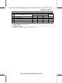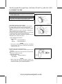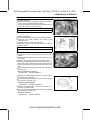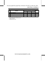
1
For Kawasaki Discount Parts Call 606-678-9623 or 606-561-4983
FJ400D
4-stroke air-cooled gasoline engine
Service Manual
www.mymowerparts.com
For Kawasaki Discount Parts Call 606-678-9623 or 606-561-4983
www.mymowerparts.com
For Kawasaki Discount Parts Call 606-678-9623 or 606-561-4983
Quick Reference Guide
General Information
1 j
Periodic Maintenance
2 j
Fuel System
3 j
Cooling System
4 j
Engine Top End
5 j
Lubrication System
6 j
Camshaft/Crankshaft
7 j
Electrical System
8 j
Troubleshooting
9 j
This quick reference guide will assist
you in locating a desired topic or procedure.
•Bend the pages back to match the
black tab of the desired chapter number with the black tab on the edge at
each table of contents page.
•Refer to the sectional table of contents
for the exact pages to locate the specific topic required.
www.mymowerparts.com
For Kawasaki Discount Parts Call 606-678-9623 or 606-561-4983
www.mymowerparts.com
For Kawasaki Discount Parts Call 606-678-9623 or 606-561-4983
FJ400D
4-stroke air-cooled gasoline engine
Service Manual
All rights reserved. No parts of this publication may be reproduced, stored in a retrieval system, or
transmitted in any form or by any means, electronic mechanical photocopying, recording or otherwise,
without the prior written permission of Quality Division/Consumer Products & Machinery Company/Kawasaki
Heavy Industries, Ltd., Japan.
No liability can be accepted for any inaccuracies or omissions in this publication, although every possible
care has been taken to make it as complete and accurate as possible.
The right is reserved to make changes at any time without prior notice and without incurring an obligation
to make such changes to products manufactured previously.
All information contained in this publication is based on the latest product information available at the time
of publication. Illustrations and photographs in this publication are intended for reference use only and may
not depict actual model component parts.
© 2004 Kawasaki Heavy Industries, Ltd.
First Edition (1): Nov. 1, 2004 (K)
www.mymowerparts.com
For Kawasaki Discount Parts Call 606-678-9623 or 606-561-4983
LIST OF ABBREVIATIONS
A
ABDC
AC
ATDC
BBDC
BDC
BTDC
°C
DC
F
°F
ft
g
h
L
ampere(s)
after bottom dead center
alternating current
after top dead center
before bottom dead center
bottom dead center
before top dead center
degree(s) Celsius
direct current
farad(s)
degree(s) Fahrenheit
foot, feet
gram(s)
hour(s)
liter(s)
lb
m
min
N
Pa
PS
psi
r
rpm
TDC
TIR
V
W
Ω
pound(s)
meter(s)
minute(s)
newton(s)
pascal(s)
horsepower
pound(s) per square inch
revolution
revolution(s) per minute
top dead center
total indicator reading
volt(s)
watt(s)
ohm(s)
Read OWNER’S MANUAL before operating.
www.mymowerparts.com
For Kawasaki Discount Parts Call 606-678-9623 or 606-561-4983
EMISSION CONTROL INFORMATION
To protect the environment in which we all live, Kawasaki has incorporated crankcase emission
(1) and exhaust emission (2) control systems (EM) in compliance with applicable regulations of
the United States Environmental Protection Agency and California Air Resources Board.
1. Crankcase Emission Control System
A sealed-type crankcase emission control system is used to eliminate blow-by gases. The
blow-by gases are led to the breather chamber through the crankcase. Then, it is led to the air
cleaner.
Oil is separated from the gases while passing through the inside of the breather chamber from
the crankcase, and then returned back to the bottom of crankcase.
2. Exhaust Emission Control System
The exhaust emission control system applied to this engine consists of a carburetor and an
ignition system having optimum ignition timing characteristics.
The carburetor has been calibrated to provide lean air/fuel mixture characteristics and optimum
fuel economy with a suitable air cleaner and exhaust system.
TAMPERING WITH EMISSION CONTROL SYSTEM PROHIBITED
Federal law and California State law prohibits the following acts or the causing thereof: (1) the
removal or rendering inoperative by any person other than for purposes of maintenance, repair,
or replacement, of any device or element of design incorporated into any new engine for the
purpose of emission control prior to its sale or delivery to the ultimate purchaser or while it is in
use, or (2) the use of the engine after such device or element of design has been removed or
rendered inoperative by any person.
Among those acts presumed to constitute tampering are the acts listed below:
Do not tamper with the original emission related part.
and internal parts
• Carburetor
Spark
plug
• Magneto or electronic ignition system
• Fuel filter element
• Air cleaner element
• Crankcase
• Cylinder head
• Breather chamber and internal parts
• Inlet pipe and tube
•
www.mymowerparts.com
For Kawasaki Discount Parts Call 606-678-9623 or 606-561-4983
Foreword
This manual is designed primarily for use by
trained mechanics in a properly equipped shop.
However, it contains enough detail and basic information to make it useful to the owner who desires to perform his own basic maintenance and
repair work. A basic knowledge of mechanics,
the proper use of tools, and workshop procedures must be understood in order to carry out
maintenance and repair satisfactorily. Whenever the owner has insufficient experience or
doubts as to his ability to do the work, all adjustments, maintenance, and repair should be
carried out only by qualified mechanics.
In order to perform the work efficiently and
to avoid costly mistakes, read the text, thoroughly familiarize yourself with the procedures
before starting work, and then do the work carefully in a clean area. Whenever special tools or
equipment are specified, do not use makeshift
tools or equipment. Precision measurements
can only be made if the proper instruments are
used, and the use of substitute tools may adversely affect safe operation.
To get the longest life out of your engine:
Follow the Periodic Maintenance Chart in the
Service Manual.
Be alert for problems and non-scheduled
maintenance.
Use proper tools and genuine Kawasaki engine parts. Genuine parts provided as spare
parts are listed in the Parts Catalog.
Follow the procedures in this manual carefully. Don’t take shortcuts.
Remember to keep complete records of maintenance and repair with dates and any new
parts installed.
•
•
•
•
•
How to Use This Manual
In this manual, the product is divided into
its major systems and these systems make up
the manual’s chapters. The Quick Reference
Guide shows you all of the product’s system
and assists in locating their chapters. Each
chapter in turn has its own comprehensive Table of Contents.
For example, if you want ignition coil information, use the Quick Reference Guide to locate
the Electrical System chapter. Then, use the
Table of Contents on the first page of the chapter to find the Ignition coil section.
Whenever you see these WARNING and
CAUTION symbols, heed their instructions!
Always follow safe operating and maintenance
practices.
WARNING
This warning symbol identifies special
instructions or procedures which, if not
correctly followed, could result in personal injury, or loss of life.
CAUTION
This caution symbol identifies special
instructions or procedures which, if not
strictly observed, could result in damage to or destruction of equipment.
This manual contains four more symbols (in
addition to WARNING and CAUTION) which will
help you distinguish different types of information.
NOTE
This
note
symbol
indicates points of par○
ticular interest for more efficient and convenient operation.
a procedural step or work to be
• Indicates
done.
○Indicates a procedural sub-step or how to do
the work of the procedural step it follows. It
also precedes the text of a WARNING, CAUTION, or NOTE.
Indicates a conditional step or what action to
take based on the results of the test or inspection in the procedural step or sub-step it follows.
In most chapters an exploded view illustration
of the system components follows the Table of
Contents. In these illustrations you will find the
instructions indicating which parts require specified tightening torque, oil, grease or a locking
agent during assembly.
www.mymowerparts.com
For Kawasaki Discount Parts Call 606-678-9623 or 606-561-4983
GENERAL INFORMATION 1-1
General Information
1
Table of Contents
Before Servicing .....................................................................................................................
Model Identification.................................................................................................................
General Specifications............................................................................................................
www.mymowerparts.com
1-2
1-4
1-5
For Kawasaki Discount Parts Call 606-678-9623 or 606-561-4983
1-2 GENERAL INFORMATION
Before Servicing
Before starting to service the engine, carefully read the applicable section to eliminate unnecessary
work. Photographs, diagrams, notes, cautions, warnings, and detailed descriptions have been included wherever necessary. Nevertheless, even a detailed account has limitations, a certain amount
of basic knowledge is required for successful work.
Especially note the following
(1) Dirt
Before removal and disassembly, clean the engine. Any dirt entering the engine, carburetor, or
other parts, will work as an abrasive and shorten the life of engine. For the same reason, before
installing a new part, clean off any dust or metal filings.
(2) Tightening Sequence
Generally, when installing a part with several bolts, nuts, or screws, start them all in their holes
and tighten them to a snug fit. Then tighten them evenly, in a staggered sequence. This is to
avoid distortion of the part and/or causing gas or oil leakage. Conversely when loosening the
bolts, nuts, or screws, first loosen all of them by about a quarter of a turn and then remove them.
Where there is a tightening sequence indication in this Service Manual, the bolts, nuts, or screws
must be tightened in the order and method indicated.
(3) Torque
When torque values are given in this Service Manual, use them. Either too little or too much
torque may lead to serious damage. Use a good quality, reliable torque wrench.
(4) Force
Common sense should dictate how much force is necessary in assembly and disassembly. If
a part seems especially difficult to remove or install, stop and examine what may be causing the
problem. Whenever tapping is necessary, tap lightly using a wooden or plastic-faced mallet. Use
an impact driver for screws (particularly for the removal of screws held by a locking agent) in order
to avoid damaging the heads.
(5) Edges
Watch for sharp edges, especially during major engine disassembly and assembly. Protect your
hands with gloves or a piece of thick cloth when lifting the engine or turning it over.
(6) High-Flash Point Solvent
A high-flash point solvent is recommended to reduce fire danger. A commercial solvent commonly available in North America is Standard solvent (generic name). Always follow manufacturer
and container directions regarding the use of any solvent.
(7) Gasket, O-ring
Do not reuse a gasket or O-ring once it has been in service. The mating surfaces around the
gasket should be free of foreign matter and perfectly smooth to avoid oil or compression leaks.
(8) Liquid Gasket, Non-Permanent Locking Agent
Follow manufacturer’s directions for cleaning and preparing surfaces where these compounds
will be used. Apply sparingly. Excessive amounts may block engine oil passages and cause
serious damage. An example of a non-permanent locking agent commonly available in North
America is Loctite Lock’n Seal (Blue).
(9) Press
A part installed using a press or driver, such as a journal, should first be coated with oil on its
outer or inner circumference so that it will go into place smoothly.
(10)Ball Bearing, Needle Bearing
Do not remove a ball bearing or a needle bearing unless it is absolutely necessary. Replace any
ball or needle bearings that were removed with new ones. Install bearings with the manufacturer
and size marks facing out, applying pressure evenly with a suitable driver to the end of the race
that contacts the press fit portion, and press it evenly over the base component.
(11) Oil Seal and Grease Seal
Replace any oil or grease seals that were removed with new ones, as removal generally damages seals.
When pressing in a seal which has manufacturer’s marks, press it in with the marks facing out.
Seals should be pressed into place using a suitable driver, which contacts evenly with the side of
seal, until the face of the seal is even with the end of the hole.
www.mymowerparts.com
For Kawasaki Discount Parts Call 606-678-9623 or 606-561-4983
GENERAL INFORMATION 1-3
Before Servicing
(12)Seal Guide
A seal guide is required for certain oil or grease seals during installation to avoid damage to
the seal lips. Before a shaft passes through a seal, apply a little oil, preferably high-temperature
grease on the lips to reduce rubber to metal friction.
(13)Circlip, Retaining Ring and Cotter Pin
When installing circlips and retaining rings, take care to compress or expand them only enough
to install them and no more. Install the circlip with its chamfered side facing load side as well.
Replace any circlips, retaining rings, and cotter pins that were removed with new ones, as removal weakens and deforms them. If old ones are reused, they could become detached while
running, leading to a problem.
(14)Lubrication
Engine wear is generally at its maximum while the engine is warming up and before all the
rubbing surfaces have an adequate lubricative film. During assembly, oil or grease (whichever
is more suitable) should be applied to any rubbing surface which has lost its lubricative film. Old
grease and dirty oil should be cleaned off. Deteriorated grease has lost its lubricative quality and
may contain abrasive foreign particles.
Don’t use just any oil or grease. Some oils and greases in particular should be used only in
certain applications and may be harmful if used in an application for which they are not intended.
This manual makes reference to molybdenum disulfide grease (MoS2) in the assembly of certain
engine parts. Always check manufacturer recommendations before using such special lubricants.
(15)Electrical Wires
All the electrical wires are either single-color or two-color and, with only a few exceptions, must
be connected to wires of the same color. On any of the two-color wires there is a greater amount
of one color and a lesser amount of a second color, so a two-color wire is identified by first the
primary color and then the secondary color. For example, a yellow wire with thin red stripes is
referred to as a “yellow/red” wire; it would be a “red/yellow” wire if the colors were reversed to
make red the main color.
(16)Replacement Parts
When there is a replacement instruction, replace these parts with new ones every time they are
removed. There replacement parts will be damaged or lose their original function once removed.
(17)Inspection
When parts have been disassembled, visually inspect these parts for the following conditions
or other damage. If there is any doubt as to the condition of them, replace them with new ones.
Abrasion
Bent
Color change
Crack
Dent
Deterioration
Hardening
Scratch
Seizure
Warp
Wear
(18)Service Data
Service Data terms are defined as follows:
“Standards” show dimensions or performances which brand-new parts or systems have.
“Service Limits” indicate the usable limits. If the measurement shows excessive wear or deteriorated performance, replace the damaged parts.
www.mymowerparts.com
For Kawasaki Discount Parts Call 606-678-9623 or 606-561-4983
1-4 GENERAL INFORMATION
Model Identification
www.mymowerparts.com
For Kawasaki Discount Parts Call 606-678-9623 or 606-561-4983
GENERAL INFORMATION 1-5
General Specifications
Item
Type of Engine
Bore × Stroke
Piston Displacement
Direction of Rotation
Compression Release
Low Idle Speed
High Idle Speed
Ignition System
RFI
Starting System
Spark Plug
Carburetor
Fuel Pump
Air Cleaner
Governor
Lubrication System
Oil Filter
Oil Pressure Switch
Oil Capacity (when engine
is completely dry)
Cooling System
Dimensions (L × W × H )
Dry Weight
FJ400D
Air-cooled, 4-stroke, OHV, single cylinder gasoline engine
82 mm × 76 mm (3.23 in. × 2.99 in.)
401 mL (24.5 cu in.)
Counterclockwise facing the PTO shaft
Automatic compression release
1 175 r/min (rpm)
4 000 r/min (rpm)
Transistorized-fly wheel magneto
Per Canada and U.S.A. requirements
Shift type electric starter
NGK BPR5ES
Float type
Diaphragm type pulse pump
–––
All speed mechanical fly weights
Pressure feed by positive displacement pump
Cartridge type full flow filter
On-Off switch
1.3 L (1.37 US qt)
Forced air cooling by fan
407 mm × 472 mm × 319 mm (16.0 in. × 18.6 in. × 12.6 in.)
31.5 kg (69.5 lb)
Specifications subject to change without notice.
www.mymowerparts.com
For Kawasaki Discount Parts Call 606-678-9623 or 606-561-4983
www.mymowerparts.com
For Kawasaki Discount Parts Call 606-678-9623 or 606-561-4983
PERIODIC MAINTENANCE 2-1
Periodic Maintenance
2
Table of Contents
Periodic Maintenance Chart ...................................................................................................
Torque and Locking Agent......................................................................................................
Specifications .........................................................................................................................
Special Tools ..........................................................................................................................
Periodic Maintenance Procedures..........................................................................................
Fuel System.........................................................................................................................
Low Idle Speed Adjustment ..............................................................................................
High Idle Speed Adjustment .............................................................................................
Fuel system Cleanliness Inspection..................................................................................
Engine Top End ...................................................................................................................
Cylinder Head Cleaning and Inspection............................................................................
Valve Clearance Inspection ..............................................................................................
Valve Clearance Adjustment.............................................................................................
Valve Seat Inspection .......................................................................................................
Valve Seat Repair .............................................................................................................
Lubrication System ..............................................................................................................
Oil Level Inspection...........................................................................................................
Oil Change ........................................................................................................................
Oil Filter Replacement ......................................................................................................
Electrical System .................................................................................................................
Spark Plug Cleaning and Gap Inspection .........................................................................
www.mymowerparts.com
2-2
2-3
2-5
2-6
2-7
2-7
2-7
2-7
2-8
2-9
2-9
2-9
2-10
2-10
2-11
2-14
2-14
2-15
2-15
2-16
2-16
For Kawasaki Discount Parts Call 606-678-9623 or 606-561-4983
2-2 PERIODIC MAINTENANCE
Periodic Maintenance Chart
To ensure satisfactory operation over an extended period of time, any engine requires normal maintenance regular intervals. The Periodic Maintenance Chart below shows periodic inspection and
maintenance items and suitable intervals. The bullet mark ( ) designates that the corresponding item
should be performed at that interval.
Some adjustments require the use of special tools or other equipment. An electronic tachometer
will facilitate setting idle and running speeds.
•
OPERATION
Daily
Check or clean air inlet screen
Check and add engine oil
Check for fuel and oil leakage
Check for loose or lost nuts and screws
Clean dust and dirt from cylinder and
cylinder head fins (1)
First
8 hr.
INTERVAL
Every Every Every Every Every
25 hr. 50 hr. 100 hr. 200 hr. 300 hr.
•
•
•
•
•
•
•
•
Tighten nuts and screws
Change engine oil
Change oil filter
Clean and re-gap spark plugs
Check and adjust valve clearance
•
Clean and lap valve seating surface
Clean combustion chamber
•
•
•
•
(1): Service more frequently under dusty conditions.
: These items must be performed with the proper tools. See your authorized Kawasaki Engine
Dealer for service, unless you have the proper equipment and mechanical proficiency.
www.mymowerparts.com
For Kawasaki Discount Parts Call 606-678-9623 or 606-561-4983
PERIODIC MAINTENANCE 2-3
Torque and Locking Agent
The following tables list the tightening torque for the major fasteners, and the parts requiring use of
a non-permanent locking agent or liquid gasket.
Letters used in the "Remarks" column mean:
L: Apply a non-permanent locking agent to the threads.
O: Apply engine oil.
S: Tighten the fasteners following the specified sequence.
SS: Apply silicone sealant.
Fastener
Fuel System
Inlet-Pipe Nuts
Control Panel Bolts
Governor Arm Clamp Nut
Choke Valve Screws
Throttle Valve Screws
Pilot Jet (Slow Jet)
Main Jet
Drain Screw
Float Chamber Mounting Bolt
Cooling System
Fan Housing Bolts
Flywheel Bolt
Engine Top End
Spark Plug
Cylinder Head Bolts
Connecting Rod Big End Cap Bolts
Valve Clearance Lock Screws
Rocker Arm Bolts
Lubrication System
Oil Filter Joint
Oil Filter
Oil Drain Plugs
Crankcase Cover Plug
Crankcase Cover Bolts
Cylinder Head Bolts
Oil Line Plugs
Oil Pressure Switch
Camshaft/Crankshaft
Valve Clearance Lock Screws
Rocker Arm Bolts
Crankcase Cover Bolts
Connecting Rod Big End Cap Bolts
Breather Valve Screw
Electrical System
Flywheel Bolt
Stator Coil Screws
N·m
Torque
kgf·m
ft·lb
5.9
6.9
5.9
0.9
0.9
0.7
2
2
9.8
0.60
0.70
0.60
0.09
0.09
0.07
0.20
0.20
1.0
52 in·lb
61 in·lb
52 in·lb
7.8 in·lb
7.8 in·lb
6.1 in·lb
17 in·lb
17 in·lb
87 in·lb
5.9
56
0.60
5.7
52 in·lb
41
22
37
5.9
6.9
28
2.2
3.8
0.60
0.70
2.9
16
27
52 in·lb
61 in·lb
21
6.9
9.8
6.9
6.9
21.6
37
3.9
9.8
0.70
1.0
0.70
0.70
2.2
3.8
0.40
1.0
61 in·lb
87 in·lb
61 in·lb
61 in·lb
16
27
35 in·lb
87 in·lb
6.9
28
21.6
5.9
3.4
0.70
2.9
2.2
0.60
0.35
61 in·lb
21
16
52 in·lb
30 in·lb
56
3.4
5.7
0.35
41
30 in·lb
www.mymowerparts.com
Remarks
L
L
S
O
O
S
S
L
SS
S
O
For Kawasaki Discount Parts Call 606-678-9623 or 606-561-4983
2-4 PERIODIC MAINTENANCE
Torque and Locking Agent
Fastener
N·m
5.9
22
20
Ignition Coil Bolts
Spark Plug
Starter Motor Mounting Bolts
Torque
kgf·m
0.60
2.2
2.0
ft·lb
52 in·lb
16
15
Remarks
The table below, relating tightening torque to thread diameter, lists the basic torque for the bolts and
nuts. Use this table for only the bolts and nuts which do not require a specific torque value. All of the
values are for use with dry solvent-cleaned threads.
Basic Torque for General Fasteners
Threads dia. (mm)
4
5
6
8
N·m
2.0
3.4
5.9
15
Torque
kgf·m
0.20
0.35
0.60
1.5
www.mymowerparts.com
ft·lb
17 in·lb
30 in·lb
52 in·lb
11
For Kawasaki Discount Parts Call 606-678-9623 or 606-561-4983
PERIODIC MAINTENANCE 2-5
Specifications
Item
Standard
Fuel System
Idle Speed: (1)
Low Idle Speed
High Idle Speed
Air Cleaner:
Type
Cleaner
Engine Top End
Valve Clearance:
Inlet, Exhaust
Valve Seating Surface Angle:
Inlet, Exhaust
Valve Seating Surface Width:
Inlet
Exhaust
Lubrication System
Engine Oil:
Type
Viscosity
Capacity
Level
Electrical System
Spark Plug Gap
1 125 ±75 r/min (rpm)
3 750 ±50 r/min (rpm)
–––
–––
0.10 ∼ 0.15 mm (0.0039 ∼ 0.0059 in.)
45°
1.1 ∼ 1.7 mm (0.043 ∼ 0.070 in.)
1.0 ∼ 1.5 mm (0.039 ∼ 0.059 in.)
SF, SG, SH or SJ class
SAE 40, SAE 30, SAE 10W-30/SAE 10W-40, or SAE 5W-20
1.1 L (1.16 US qt) (When filter is not removed)
1.3 L (1.37 US qt) (When filter is removed)
Operating range (grid area) on dipstick
0.7 ∼ 0.8 mm (0.028 ∼ 0.031 in.)
(1) Idle speeds may vary depending on each equipment. Refer to the equipment specification.
www.mymowerparts.com
For Kawasaki Discount Parts Call 606-678-9623 or 606-561-4983
2-6 PERIODIC MAINTENANCE
Special Tools
Valve Seat Cutter, 45° 57001-1115
32:
Valve Seat Cutter Holder,
57001-1126
Valve Seat Cutter, 45° 57001-1116
35:
Valve Seat Cutter Holder Bar:
57001-1128
Valve Seat Cutter, 32° 57001-1121
35:
Oil Filter Wrench:
57001-1249
Valve Seat Cutter, 32° 57001-1122
38.5:
www.mymowerparts.com
7:
For Kawasaki Discount Parts Call 606-678-9623 or 606-561-4983
PERIODIC MAINTENANCE 2-7
Periodic Maintenance Procedures
Fuel System
NOTE
○High and low idle speeds may very depending on the
equipment on which the engine is used. Refer to the
equipment specification.
Low Idle Speed Adjustment
all external loads from the engine.
• Disconnect
Start
the
engine
and warm it up thoroughly.
•
WARNING
Always keep your hands clear of the moving parts.
the throttle lever on dash to the idle position, and
• Move
hold the throttle lever on the carburetor in closed position
(turn the governor arm clockwise all the way) and adjust
the low idle speed screw [A] until the engine idles at specified speed.
Idle Speed (Carburetor Idle rpm)
950 ±50 rpm (r/min)
the throttle lever and adjust the low idle speed
• Release
set screw [A] on the control panel to obtain the specified
governed low idle speed.
Low Idle Speed (Governed Idle rpm)
1 125 ±75 rpm (r/min)
High Idle Speed Adjustment
NOTE
○High idle speed adjustment should be made after the
idle speed adjustment is performed.
CAUTION
Do not adjust high idle speed with the air cleaner
removed.
• Start and warm up the engine thoroughly.
www.mymowerparts.com
For Kawasaki Discount Parts Call 606-678-9623 or 606-561-4983
2-8 PERIODIC MAINTENANCE
Periodic Maintenance Procedures
WARNING
Always keep your hands clear of the moving parts.
the throttle lever at a dash to the high idle position
• Move
and adjust the high idle speed set screw [A] to obtain the
specified high idle speed.
High Idle Speed (Governed Idle rpm)
3 750 ±50 rpm (r/min)
the idle speed, and readjust the idle speed if nec• Check
essary.
Fuel system Cleanliness Inspection
WARNING
Gasoline is extremely flammable and can be explosive under certain conditions. Turn the engine
switch OFF. Do not smoke. Make sure the area is
well-ventilated and free from any source of flame
or sparks; this includes any appliance with a pilot
light.
a suitable container [A] under the carburetor drain
• Place
screw [B].
the drain screw to drain the carburetor and check
• Loosen
to see if water or dirt has accumulated in the carburetor.
the drain screw
• Tighten
If
any
water
or dirt is found, clean the carburetor (see
• Carburetor Cleaning
in the Fuel System chapter).
www.mymowerparts.com
For Kawasaki Discount Parts Call 606-678-9623 or 606-561-4983
PERIODIC MAINTENANCE 2-9
Periodic Maintenance Procedures
Engine Top End
Cylinder Head Cleaning and Inspection
the valves (see Valve Mechanism Removal/In• Remove
stallation in the Engine Top End chapter).
the carbon deposits from the head and exhaust
• Scrape
port with a suitable tool [A].
○To avoid gouging, use scrapers that are made of a mate-
•
rial that will not cause damage.
Clean the head in a bath of high-flash point solvent and
dry it with compressed air.
WARNING
Clean the cylinder head in a well-ventilated area,
and take care that there are no sparks or flame anywhere near the working area; this includes any appliance with a pilot light. Do not use gasoline or a
low-flash point solvent to clean the cylinder head.
A fire or explosion could result.
edge [A] across the mating surface of the head at
• Straight
several different points, and measure warp by inserting a
thickness gauge [B] between the straightedge and head.
If warp exceeds the service limit, repair the mating surface. Replace the cylinder head if the mating surface is
badly damaged.
Cylinder Head Warp
Service Limit: 0.03 mm (0.001 in.)
the cylinder head for cracks or other damage.
• Check
Cracks
visible to the eye may be detached by using
• a metal not
crack detection system (Visual color check: com-
•
•
monly found at automotive parts tore).
If a crack is present in the cylinder head, replace it.
Inspect the mating surface for burrs and nicks.
Valve Clearance Inspection
NOTE
○Valve clearance must be checked when the engine is
cold (at room temperature).
the rocker cover (see Cylinder Head Assembly
• Remove
Removal in the Engine Top End chapter).
the piston at top dead center (TDC) of the compres• Place
sion stroke turning the crankshaft rotational direction.
www.mymowerparts.com
For Kawasaki Discount Parts Call 606-678-9623 or 606-561-4983
2-10 PERIODIC MAINTENANCE
Periodic Maintenance Procedures
check the valve clearance.
•○Then
Using a thickness gauge [A], measure the valve clearance
between the rocker arm [B] and the valve stem end.
If the valve clearance is incorrect, adjust it.
Valve Clearance (when cold)
Inlet, Exhaust 0.10 ∼ 0.15 mm (0.0039 ∼ 0.0059 in.)
Valve Clearance Adjustment
valve repairs change the valve clearance, adjust
• Since
the valve clearance to the specification.
the cylinder head and install the cylinder head
• Assemble
assembly on the block (see Cylinder Head Assembly In-
•
•
•
stallation in the Engine Top End chapter).
Turn the crankshaft to the proper direction until the piston
is at TDC of the compression stroke (described above).
Loosen the lock screw [A] and valve clearance adjusting
nuts [B].
Insert a thickness gauge [C] between the rocker arm and
valve stem, and tighten the adjusting nut until the thickness gauge begins to bind between the rocker arm and
valve stem end. Use a sweeping motion with the thickness gauge while making this adjustment.
Valve Clearance (when cold)
Inlet, Exhaust 0.10 ∼ 0.15 mm (0.0039 ∼ 0.0059 in.)
the adjusting nut with a wrench, tighten the lock
• Holding
screw to the specified torque.
Torque - Valve Clearance Lock screw: 6.9 N·m (0.70 kgf·m,
61 in·lb)
CAUTION
Do not overtighten.
any clearance that was adjusted. Readjust if
• Remeasure
necessary.
Valve Seat Inspection
the valve (see Valve Mechanism Removal/Instal• Remove
lation in the Engine Top End chapter).
the valve seats for damage.
• Inspect
If the seats are warped or distorted beyond recondition-
•
•
•
•
•
ing, replace the cylinder head.
Pitted or worn valve seats can be refaced. Lap the valves
to the seats after refacing.
Coat the valve seat with machinist’s dye.
Push the valve into the guide.
Rotate the valve against the seat with a Lapper.
Pull the valve out, and check the seating pattern on the
valve head. It must be the correct width [A] and even all
the way around.
www.mymowerparts.com
For Kawasaki Discount Parts Call 606-678-9623 or 606-561-4983
PERIODIC MAINTENANCE 2-11
Periodic Maintenance Procedures
NOTE
○The valve stem and guide must be in good condition or
this check will not be valid.
Good [A]
Too Wide [B]
Too Narrow [C]
Uneven [D]
If the valve seating pattern is not correct, repair the seat.
Valve Seating Surface Width (STD)
Inlet
1.1 ∼ 1.7 mm (0.043 ∼ 0.070 in.)
Exhaust
1.0 ∼ 1.5 mm (0.039 ∼ 0.059 in.)
Valve Seat Repair
the manufacturer’s instructions for use of valve
• Follow
seat cutters.
Special Tools - Valve Seat Cutter Holder, 7: 57001-1126
Valve Seat Cutter Holder Bar: 57001-1128
Inlet Valve
Valve Seat Cutter, 45° Valve Seat Cutter, 32° -
35: 57001-1116
38.5: 57001-1122
Exhaust Valve
Valve Seat Cutter, 45° -
32: 57001-1115
Valve Seat Cutter, 32° -
35: 57001-1121
If the manufacturer’s instructions are not available, use
the following procedure.
Seat Cutter Operating Cares
1. This valve seat cutter is designed only for valve seat
repair. Therefore the cutter must not be used for other
purposes.
2. Do not drop or hit the valve seat cutter, or the diamond
particles may fall off.
3. Do not fail to apply engine oil to the valve seat cutter
before grinding the seat surface. Also wash off ground
particles sticking to the cutter with washing oil.
NOTE
○Do not use a wire brush to remove the metal particles
from the cutter. It will take off the diamond particles.
4. Setting the valve seat cutter holder [A] in position, operate the cutter [B] with one hand [C]. Do not apply too
much force to the diamond portion.
NOTE
○Prior to grinding, apply oil to the cutter, and during the
operation wash off any ground particles sticking to the
cutter with washing oil.
5. After use wash the cutter with washing oil and apply a
thin layer of engine oil before storing.
www.mymowerparts.com
For Kawasaki Discount Parts Call 606-678-9623 or 606-561-4983
2-12 PERIODIC MAINTENANCE
Periodic Maintenance Procedures
Marks Stamped on the Cutter
The marks stamped on the back of the cutter represent the
following.
45°
24.5
Cutter angle [A]
Cutter diameter of cutter [B]
Operating Procedures
Clean the seat area carefully.
Recondition the valve seats with the valve seat cutters
(45°, 32°) and lap the valves.
Check the seats for good contact all the way around with
machinist’s dye.
Measure the seat width [A]. If it is more than the STD
width, the seating surface should be refaced.
If the valve seating pattern is not correct, repair the seat.
•
•
•
•
the seat with machinist’s dye.
• Coat
a 45° cutter [A] to the holder and slide it into the valve
• Fit
guide.
○Resurface the valve seat with a 45° cutter, removing only
enough material to produce a smooth and concentric
seat.
CAUTION
Do not grind the seat too much. Overgrinding will
reduce valve clearance by sinking the valve into the
head. If the valve sinks too far into the head, it will
be impossible to adjust the clearance, and the cylinder head must be replaced. Do not turn the cutter
counterclockwise or drop it against the seat, or it
will be dulled.
www.mymowerparts.com
For Kawasaki Discount Parts Call 606-678-9623 or 606-561-4983
PERIODIC MAINTENANCE 2-13
Periodic Maintenance Procedures
a 32° seat cutter [A] to narrow the seat width to the
• Use
STD width.
○Turn the seat cutter one turn at a time while pressing down
very lightly. Check the seat width after each turn.
CAUTION
The 32° cutter removes material very quickly.
Check the seat width frequently to prevent over
grinding.
NOTE
○Keep the seat width as close as possible to the STD
width.
a light pass with the 45° cutter to remove any pos• Make
sible burrs at the edge of the seat.
resurfacing the seat, inspect for even valve seating.
•○After
Apply a machinist’s dye to the valve face, insert the
valve, and snap it closed against the seat several times.
The valve surface should show good contact all the way
around. Be sure the valve seat is centered on the valve
face. The position of the valve in the seat is evident after
lapping the valve.
If the seat does not make proper contact, lap the valve
into seat with a lapper.
the face of valve sparingly with a fine lapping com• Coat
pound.
the lapper [A], to grip top of the valve [B]. Rotate the
• Use
valve in a circular motion to lap the valve to the seat.
the valve slightly from the seat every 8 to 10 strokes,
• Lift
continue lapping operation until a uniform ring appears
around entire surface of the valve face.
lapping is completed, wash all parts in solvent to
• When
remove lapping compound. Dry the parts thoroughly.
the position of the lapping mark on the valve face.
• Note
The lapping mark should appear on or near the center of
•
the valve face.
When the engine is assembled, be sure to adjust the valve
clearances (see Valve Clearance Adjustment in this chapter).
www.mymowerparts.com
For Kawasaki Discount Parts Call 606-678-9623 or 606-561-4983
2-14 PERIODIC MAINTENANCE
Periodic Maintenance Procedures
Lubrication System
Oil Level Inspection
the engine on a level surface.
• Place
Remove
the oil filler cap [A] and wipe its dipstick [B] with
• a clean cloth.
the dipstick into gauge hole [C] without screwing it
• Insert
in, then check the oil Level.
CAUTION
Always insert the dipstick into the gauge hole so
that the taper part [A] of the oil filler cap is facing
the starter side [B].
oil level should be in the range of “H” mark and “L”
• The
mark [A] (grid area) on the dipstick.
If the oil level is “L” range [B] or below, add enough engine
oil to bring oil level to the range of “H” mark and “L” mark.
CAUTION
Do not add more oil above the range of “H” mark
and “L” mark. Excess oil will cause a smoking condition.
○Use the same type and make of oil that is already in the
engine.
NOTE
○If the engine oil type and make are unknown, use any
brand of the specified oil to top up the level in preference
to running the engine with the oil level low. Then at your
earliest convenience, change the oil completely.
If the oil level is “H” range [C] or above, drain the excess
oil by loosening the drain plug.
www.mymowerparts.com
For Kawasaki Discount Parts Call 606-678-9623 or 606-561-4983
PERIODIC MAINTENANCE 2-15
Periodic Maintenance Procedures
Oil Change
the oil after first 8 hours of operation. Thereafter
• Change
change oil every 100 hours.
and warm up the engine so the oil will drain easily.
• Start
Stop the engine.
the engine on a level surface.
• Place
Place
a
container under the engine.
• Removesuitable
the drain plug [A] and drain the oil.
•
WARNING
Be careful of hot oil when drained. It may be hot
enough to burn you severely.
the O-ring [B] with a new one.
• Replace
Install
the
drain plug with the O-ring and tighten it.
•
Torque - Oil Drain Plugs: 6.9 N·m (0.70 kgf·m, 61 in·lb)
the oil filler cap and pour in the specified type
• Remove
and amount of oil.
Engine Oil
Type:
SF, SG, SH or SJ Class
Viscosity: SAE 40, SAE 30, SAE 10W-30/SAE 10W-40,
or SAE 5W-20
Capacity: 1.1 L (1.16 US qt) (When filter is not
removed)
1.3 L (1.37 US qt) (When filter is removed)
Oil Filter Replacement
the engine oil (see Oil Change in this chapter).
• Drain
a strap wrench or oil filter wrench [A], remove the
• Using
oil filter [B].
Special Tool - Oil Filter Wrench: 57001-1249
○When unscrewing the oil filter, place a suitable container
beneath the oil drip tray to receive oil from the oil filter
and oil passages in the engine. Turn the filter counterclockwise to remove it.
engine oil to the seal [A].
• Apply
Install
•○Turn thenewfilterfilter.
until the seal contacts mounting surface [B]
•
•
•
of the engine. Then turn the filter 2/3 to 3/4 rotations by
HAND(S) to install it.
Pour in the specified type and amount of oil (see Oil
Change in this chapter).
Run the engine at slow idle speed 2 minutes. Check for
leaks around the engine.
Stop the engine. Check the oil level (see Oil Level Inspection in this chapter).
www.mymowerparts.com
For Kawasaki Discount Parts Call 606-678-9623 or 606-561-4983
2-16 PERIODIC MAINTENANCE
Periodic Maintenance Procedures
Electrical System
Spark Plug Cleaning and Gap Inspection
the spark plug (see Spark Plug Removal in the
• Remove
Electrical System chapter).
If the plug is oily or has carbon build up on it, clean the
plug using a high-flash point solvent and a wire brush or
other suitable tool.
If the spark plug electrodes are corroded or damaged,
or if the insulator is cracked, replace the plug. Use the
standard spark plug or its equivalent.
Insulator [A]
Center Electrode [B]
Plug Gap [C]
Side Electrode [D]
the gap with a wire-type thickness gauge.
• Measure
If the gap is incorrect, carefully bend the side electrode
with a suitable tool to obtain the correct gap.
Spark Plug Gap
Standard: 0.7 ∼ 0.8 mm (0.028 ∼ 0.031 in.)
www.mymowerparts.com
For Kawasaki Discount Parts Call 606-678-9623 or 606-561-4983
FUEL SYSTEM 3-1
Fuel System
Table of Contents
Exploded View........................................................................................................................
Specifications .........................................................................................................................
Governor Link Mechanism......................................................................................................
Control Panel Assembly Removal ....................................................................................
Control Panel Assembly Installation .................................................................................
Governor Arm Removal ....................................................................................................
Governor Arm Installation .................................................................................................
Governor Assembly Removal/Inspection..........................................................................
Governor Assembly Installation ........................................................................................
Governor Shaft Removal ..................................................................................................
Governor Shaft Installation ...............................................................................................
Carburetor ..............................................................................................................................
Fuel and Air Flow ..............................................................................................................
Low Idle Speed Adjustment ..............................................................................................
High Idle Speed Adjustment .............................................................................................
High Altitude Operation.....................................................................................................
Main Jet Replacement ......................................................................................................
Fuel system Cleanliness Inspection..................................................................................
Carburetor Removal..........................................................................................................
Carburetor Installation.......................................................................................................
Carburetor Disassembly/Assembly ..................................................................................
Carburetor Cleaning..........................................................................................................
Carburetor Inspection .......................................................................................................
Fuel Pump, Fuel Filter ............................................................................................................
Fuel Pump.........................................................................................................................
Fuel Pump Inspection .......................................................................................................
www.mymowerparts.com
3-2
3-4
3-5
3-5
3-5
3-5
3-6
3-6
3-7
3-7
3-7
3-8
3-8
3-12
3-12
3-12
3-12
3-13
3-13
3-13
3-14
3-15
3-16
3-18
3-18
3-18
3
For Kawasaki Discount Parts Call 606-678-9623 or 606-561-4983
3-2 FUEL SYSTEM
Exploded View
www.mymowerparts.com
For Kawasaki Discount Parts Call 606-678-9623 or 606-561-4983
FUEL SYSTEM 3-3
Exploded View
No.
1
2
3
4
5
6
7
8
9
Fastener
Inlet-Pipe Nuts
Control Panel Bolts
Governor Arm Clamp Nut
Choke Valve Screws
Throttle Valve Screws
Pilot Jet (Slow Jet)
Main Jet
Drain Screw
Float Chamber Mounting Bolt
N·m
5.9
6.9
5.9
0.9
0.9
0.7
2
2
9.8
Torque
kgf·m
0.60
0.70
0.60
0.09
0.09
0.07
0.20
0.20
1.0
10. High Idle Speed Screw
11. Low Idle Speed Screw
12. Governor Arm
13. Governor Shaft
14. Governor Assembly
L: Apply a non-permanent locking agent to the threads.
O: Apply engine oil.
R: Replacement Parts
www.mymowerparts.com
ft·lb
52 in·lb
61 in·lb
52 in·lb
7.8 in·lb
7.8 in·lb
6.1 in·lb
17 in·lb
17 in·lb
87 in·lb
Remarks
L
L
For Kawasaki Discount Parts Call 606-678-9623 or 606-561-4983
3-4 FUEL SYSTEM
Specifications
Item
Caburetors Specifications
Make/ Type
Throttle Bore Diameter
Venturi Diameter
Main Jet (MJ)
Pilot Jet (PJ)
Pilot Screw Turns Out (PS)
(Idle Mixture Screw Turns Out)
Float Level
Idle Speed (1)
Low Idle Speed
High Idle Speed
Air Cleaner
Type
Cleaner
Fuel
Fuel Requirement
Fuel Pump
Type
Governor
Type
Standard
NIKKI/6C1026-511
26 mm (1.02 in.)
20 mm (0.79 in.)
#110
#50
2 3/4 ±3/8
Float parallel to carburetor body
1 125 ±75 r/min (rpm)
3 750 ±50 r/min (rpm)
–––
–––
Unleaded regular grade gasoline
Pulse-diaphragm pump
Flyweight all speed governor
(1) Idle speeds may vary depending on each mounting equipment. Refer to the mounting equipment
specification.
www.mymowerparts.com
For Kawasaki Discount Parts Call 606-678-9623 or 606-561-4983
FUEL SYSTEM 3-5
Governor Link Mechanism
Control Panel Assembly Removal
• Remove the control panel mounting bolts [A].
the control panel assembly [A] while unhooking
• Remove
the governor spring [B] end loop at the engine speed control lever [C].
Control Panel Assembly Installation
installing the control panel assembly, check to see
• Before
that the engine speed control lever [A] move smoothly in
•
all directions.
If any part is worn or damaged, replace the control panel
assembly.
Hook the governor spring end loop.
the control panel assembly with the mounting bolts
• Install
[A].
installation, adjust the low idle speed and high idle
• After
speed to the specifications (see Low/High Idle Speed Adjustment in the Periodic Maintenance chapter).
Governor Arm Removal
the control panel assembly (see Control Panel
• Remove
Assembly Removal in this chapter).
the clamp nut [A] and take off the governor arm
• Loosen
[B].
the throttle link rod spring [C] end loop and clear
• Unhook
the throttle link rod lower end [D].
www.mymowerparts.com
For Kawasaki Discount Parts Call 606-678-9623 or 606-561-4983
3-6 FUEL SYSTEM
Governor Link Mechanism
Governor Arm Installation
the governor arm [A] onto the governor shaft [B]
• Install
temporarily.
sure the link spring [C] around the throttle link rod [D]
• Be
is in place and that it pulls the governor arm and throttle
lever [E] toward each other.
Loosen the clamp nut [F] on the governor arm enough to
move the governor shaft.
Turn the top end of the governor arm counterclockwise
[G] to fully open the carburetor throttle valve and hold it
there.
Turn the governor shaft counterclockwise, fully turn the
shaft to end of its travel.
Tighten the clamp nut.
○There should be no gap between the governor arm and
the snap pin on the governor shaft.
•
•
•
•
Torque - Governor Arm Clamp Nut: 5.9 N·m (0.60 kgf·m, 52
in·lb)
the control panel assembly, and connect the gov• Install
ernor arm with the governor spring.
Governor Assembly Removal/Inspection
the crankcase cover (see Crankcase Cover Re• Remove
moval in the Camshaft/Crankshaft chapter).
check the governor assembly as built in the
• Visually
crankcase cover for damage or wear.
CAUTION
Do not remove the governor gear assembly unless
the parts are to be replaced. The parts cannot be
reused once they are removed.
removing the governor assembly [A] for replacing,
• When
use two screw drivers [B] of an appropriate size.
CAUTION
Protect the gasket-mount surface of the crankcase
cover when removing the governor assembly with
the screw drivers.
www.mymowerparts.com
For Kawasaki Discount Parts Call 606-678-9623 or 606-561-4983
FUEL SYSTEM 3-7
Governor Link Mechanism
Governor Assembly Installation
• Install the sleeve [A] on the governor assembly [B].
CAUTION
First install the sleeve.
The sleeve cannot be installed after the governor
gear assembly has been installed.
install, first place the thrust washer [C] on the boss of
• To
the shaft [D]. Then, install the governor assembly (with
•
the sleeve attached) on the shaft so that step [E] is fitted
securely in groove [F].
After installing the assembly, turn the governor by hand to
make sure that the governor weights [G] and the sleeve
move smoothly.
Governor Shaft Removal
• Remove:
Crankcase cover (see Crankcase Cover Removal in the
•
Camshaft/Crankcase chapter)
Crankshaft (see Crankshaft Removal in the
Camshaft/Crankcase chapter)
Governor arm (see Governor Arm Removal in this chapter).
Snap Pin [A]
Governor Shaft [B]
Oil Seal [C]
Washer [D]
Be sure to replace any oil seal removed with a new seal.
Governor Shaft Installation
engine oil to the governor shaft.
• Apply
Install
washer [A] to the governor shaft [B] and insert
• it from the
the crankcase inside.
the oil seal [A] into the crankcase after the gover• Install
nor shaft [B] is inserted in the crankcase, and so that the
•
•
•
marks [C] face out.
Press in the new oil seal using a press or suitable tools
until it is flush with crankcase surface [D].
Hold the governor shaft with the snap pin.
Check that the governor shaft moves smoothly in its operating range.
www.mymowerparts.com
For Kawasaki Discount Parts Call 606-678-9623 or 606-561-4983
3-8 FUEL SYSTEM
Carburetor
Fuel and Air Flow
The main system of the carburetor consists of the main jet [A], valve seat [B] main nozzle [C], and
the main air passage [D] (main air jet [E]). The main system meters fuel to the engine during moderate
to heavy load conditions. Fuel flows through the main jet and into the main nozzle, where it is joined
by air from the main air passage (main air jet). The resulting mixture flows out the end of the main
nozzle into the carburetor bore, where it is atomized by the high speed air flow, and carried into the
engine.
www.mymowerparts.com
For Kawasaki Discount Parts Call 606-678-9623 or 606-561-4983
FUEL SYSTEM 3-9
Carburetor
Dummy Page
www.mymowerparts.com
For Kawasaki Discount Parts Call 606-678-9623 or 606-561-4983
3-10 FUEL SYSTEM
Carburetor
The slow system includes the slow jet (pilot jet) [F], idle screw [G] (idle mixture screw), slow air breed
jet [H], idle port [I], and the slow port [J]. The slow system meters the fuel/air mixture while the engine
is idling and running under a light load. Under these conditions there is very little air flow through the
carburetor bore; so little that it is not enough to draw fuel through the main system of the carburetor
and atomize it. Instead, the fuel is drawn through the slow system, since the nearly closed throttle
valve [K] causes high speed air flow past the idle port and slow port (even at low engine speed).
Fuel flow in the slow system is metered by the slow jet (pilot jet). Air for better atomization is admitted
via the air bleed jet in the mouth of the carburetor. The fuel/air mixture passes into the bore of the
carburetor side stream of the throttle valve through the slow port and idle port. While the throttle valve
is almost closed, it covers the small slow port opening into the bore from the slow system. As the
throttle valve begins to open, it uncovers the slow port, allowing more fuel/air mixture to flow. The
extra flow is needed because the engine starts to run faster as the throttle is opened. The slow screw
controls the amount of fuel/air mixture allowed through the idle port, but does not meter the slow port.
A moderate amount of air comes in around the throttle valve at an idle, so adjusting the idle screw
changes the fuel/air ratio. Turning the idle screw (idle mixture screw) out (counterclockwise) enrichens
the mixture; turning it in (clockwise) leans the mixture.
www.mymowerparts.com
For Kawasaki Discount Parts Call 606-678-9623 or 606-561-4983
FUEL SYSTEM 3-11
Carburetor
www.mymowerparts.com
For Kawasaki Discount Parts Call 606-678-9623 or 606-561-4983
3-12 FUEL SYSTEM
Carburetor
Low Idle Speed Adjustment
to the Low Idle Speed Adjustment in the Periodic
• Refer
Maintenance chapter.
High Idle Speed Adjustment
to the High Idle Speed Adjustment in the Periodic
• Refer
Maintenance chapter.
High Altitude Operation
At high altitude, the standard carburetor air-fuel mixture
will be excessively rich. Performance will decrease, and
fuel consumption will increase. High altitude performance
can be improved by installing a smaller diameter main-jet in
the carburetor and correct idle speed.
NOTE
○The main jet high altitude kits are available if the equipment is to be used in the high altitudes. The main jet
numbers are stamped on ends of the main jets.
High Altitude Main Jet
Altitude
Main Jet No.
0 ∼ 1 000 m (0 ∼ 3 000 ft)
#110
1 000 ∼ 2 000 m (3 000 ∼ 6 000 ft)
#108
2 000 m (6 000 ft) and higher
#106
Main Jet Replacement
the engine (equipment) on a level surface.
• Place
Close
the fuel shut off valve in the equipment.
• Drain the
in the carburetor completely by unscrewing
• the drain fuel
screw [A] at the bottom of the float chamber
•
•
(see Fuel System Cleanliness Inspection in the Periodic
Maintenance chapter).
Remove the carburetor (see Carburetor Removal in this
chapter).
Unscrew the float chamber mounting bolt [B] and take off
the float chamber [C] and gasket.
a properly sized blade screw driver, carefully re• Using
place the main jet [A] with a new one for altitude expected.
www.mymowerparts.com
For Kawasaki Discount Parts Call 606-678-9623 or 606-561-4983
FUEL SYSTEM 3-13
Carburetor
the float chamber gasket with a new one.
• Replace
Install
the
chamber and gasket.
• Tighten floatfloatchamber
mounting bolt [A] as shown the fig• ure.
Drain Screw [B]
Fuel Inlet Joint [C]
Torque - Float Chamber Mounting Bolt: 9.8 N·m (1.0 kgf·m,
87 in·lb)
Fuel system Cleanliness Inspection
to the Fuel System Cleanliness Inspection in the
• Refer
Periodic Maintenance chapter.
Carburetor Removal
WARNING
Gasoline is extremely flammable and can be explosive under certain conditions. Turn the engine
switch OFF. Do not smoke. Make sure the area is
well- ventilated and free from any source of flame
or sparks; this includes any appliance with a pilot
light.
the breather hose [A].
• Disconnect
Remove
the
pipe [B].
• Turn the fuelinlet
shut
off valve to the OFF position in the
• equipment.
the carburetor completely by unscrewing the drain
• Drain
screw at the bottom of the float chamber (see Fuel System Cleanliness Inspection in the Periodic Maintenance
chapter).
the fuel tube (equipment part) at the fuel inlet
• Disconnect
joint [A] of the carburetor.
the throttle link spring [B] at the throttle shaft lever
• Unhook
[C] top end with a long nose pliers.
the throttle link rod [D] from the throttle shaft lever.
• Unhook
Remove
carburetor, the gasket, and the insulator.
• Check thetheinsulator
• If the insulator is notforin damage.
good condition, replace it with a
new one.
Carburetor Installation
the mating surfaces of the carburetor and inlet pipe,
• Clean
and fit the new gaskets.
care not to bend the throttle link rod during instal• Take
lation. Make sure that the link spring around the throttle
•
link rod is in place and that it pulls the governor arm and
carburetor throttle shaft lever toward each other.
Adjust the idle speed (see Low/High Idle Speed Adjustment in the Periodic Maintenance chapter).
www.mymowerparts.com
For Kawasaki Discount Parts Call 606-678-9623 or 606-561-4983
3-14 FUEL SYSTEM
Carburetor
Carburetor Disassembly/Assembly
to the illustration shown for disassembly and as• Refer
sembly.
are several passage plugs (ball plugs) in the car• There
buretor body. Do not remove.
disassembly, mark the out side of choke valve and
• Before
throttle valves for assembling them.
the choke valve and throttle valve on the shaft as
• Install
the out side mark of them facing out side.
the float pin into the carburetor body.
• Drive
Assemble
parts with recommended tightening
• torque (seecarburetor
Exploded View).
1. Screw
2. Throttle Valve
3. Throttle Shaft
4. Dust Seal
5. Choke Valve
6. Choke Shaft
7. Spring
8. Snap Ring
9. Pilot Jet Plug
10. Pilot Jet
11. Low Idle Speed Screw
12. Main Jet
13. Pilot Screw Plug
14. Pilot Screw
15. Float Valve
16. Float
17. Float Pin
18. Gasket
19. Float Chamber Assy
20. Float Chamber Bolt
www.mymowerparts.com
For Kawasaki Discount Parts Call 606-678-9623 or 606-561-4983
FUEL SYSTEM 3-15
Carburetor
Carburetor Cleaning
WARNING
Clean the carburetor in a well-ventilated area, and
take care that there is no sparks or flame anywhere
near the working area; this includes any electrical
appliance with a pilot light. Because of the danger
of highly flammable liquids, do not use gasoline or
low-flash point washing to clean the carburetors.
CAUTION
Do not use compressed air on an assembled carburetor, or the floats may be crushed by the pressure.
Remove as many rubber or plastic parts from the
carburetor as possible before cleaning the carburetor with a washing. This will prevent to damage
or deterioration of the parts.
The carburetor body has plastic parts that cannot
be removed. Do not use a strong carburetor washing which could attack these parts; instead, use a
mild high-flash point washing safe for plastic parts.
Do not use wire or any other hard instrument to
clean carburetor parts, especially jets, as they may
be damaged.
the carburetor (see Caburetor Disassem• Disassemble
bly/Assembly in this chapter).
all the carburetor metal parts in a carburetor
• Immerse
cleaning solution and clean them.
the parts in water and dry them with compressed
• Rinse
air.
not use rags or paper to dry parts. Lint may plug the
• Do
holes or passages.
air through the holes and fuel passages with the
• Blow
compressed air. All holes must be open.
the carburetor (see Carburetor Disassem• Assemble
bly/Assembly in this chapter).
www.mymowerparts.com
For Kawasaki Discount Parts Call 606-678-9623 or 606-561-4983
3-16 FUEL SYSTEM
Carburetor
Carburetor Inspection
WARNING
Gasoline is extremely flammable and can be explosive under certain. Turn the engine switch “OFF” .
Do not smoke. Make sure the area is well ventilated
and free from any source of flame or sparks; this
includes any appliance with a pilot light.
the carburetor body for damage. Flange sealing
• Inspect
surfaces should be smooth and free of burrs and nicks.
the throttle and choke shafts to check that the throttle
• Turn
and choke butterfly valves move smoothly.
•
•
•
If the valves do not move smoothly, replace the carburetor
body and/or throttle shaft and choke shaft assembly.
Check the gasket on the carburetor body.
If the gasket is not in good condition, replace it.
Check the other parts of the carburetor for wear or damage. Replace the part if necessary.
Clean and check the float level as follows.
CAUTION
Do not push down on the float during float level
checking.
www.mymowerparts.com
For Kawasaki Discount Parts Call 606-678-9623 or 606-561-4983
FUEL SYSTEM 3-17
Carburetor
the float [A] assembly installed onto the carburetor
• With
body [B], hold the carburetor upside down at eye level.
Gently support the float with a finger and bring it down
slowly so that the float arm tab [C] just touches the float
valve [D]. The float lower surface [E] should be parallel
with the carburetor body mating surfaces [F].
If the float position is not correct, replace the float with a
new one.
the float valve for excessive wear or damage. The
• Inspect
tip should be smooth, without any grooves, scratches, or
tears. The rod at the other end of the needle should move
smoothly when push in and released.
Good [A]
Not Good [B]
If either the needle or the seat is worn or damaged, replace the float assembly and carburetor body as a set.
www.mymowerparts.com
For Kawasaki Discount Parts Call 606-678-9623 or 606-561-4983
3-18 FUEL SYSTEM
Fuel Pump, Fuel Filter
The diaphragm in the fuel pump operates by the pulse
generated in the crankcase, and the fuel pump supplies fuel
to the carburetor.
The fuel pump disassembly is not recommended, if any
damage for the pump is noticed replace it with a new one.
Fuel Pump
Inlet [A]
Pulse [B]
Outlet [C]
Fuel Pump Inspection
the vent hole [A] and filter [B] for plugging or clog• Check
ging.
If vent hole and filter are plugged or clogged, remove the
foreign matter from them.
Fuel Flow Test
Before this test, be sure the battery is fully charged.
WARNING
Gasoline is extremely flammable and can be explosive under certain conditions. Turn the ignition
switch OFF. Do not smoke. Make sure the area is
well-ventilated and free from any source of flame
or sparks; this includes any appliance with a pilot
light.
the fuel pump outlet nozzle from the tube.
• Disconnect
a suitable hose to the outlet nozzle.
• Connect
Run
the
lower
of the hose into a container.
• Start the engine,endCheck
fuel flow.
• If fuel flow is none or little,thereplace
the fuel pump.
Check for clogged or damaged tubes and fuel filter. Replace the faulty parts.
www.mymowerparts.com
For Kawasaki Discount Parts Call 606-678-9623 or 606-561-4983
COOLING SYSTEM 4-1
Cooling System
Table of Contents
Exploded View........................................................................................................................
Cooling Fan ............................................................................................................................
Cooling Fan Removal .......................................................................................................
Cooling Fan Installation ....................................................................................................
Cooling Fan Inspection .....................................................................................................
www.mymowerparts.com
4-2
4-4
4-4
4-4
4-4
4
For Kawasaki Discount Parts Call 606-678-9623 or 606-561-4983
4-2 COOLING SYSTEM
Exploded View
www.mymowerparts.com
For Kawasaki Discount Parts Call 606-678-9623 or 606-561-4983
COOLING SYSTEM 4-3
Exploded View
No.
1
2
Fastener
Fan Housing Bolts
Flywheel Bolt
N·m
5.9
56
Torque
kgf·m
0.60
5.7
3. Fan Housing
4. Fan
www.mymowerparts.com
ft·lb
52 in·lb
41
Remarks
For Kawasaki Discount Parts Call 606-678-9623 or 606-561-4983
4-4 COOLING SYSTEM
Cooling Fan
Cooling Fan Removal
to the Flywheel Removal in the Electrical System
• Refer
chapter.
Cooling Fan Installation
to the Flywheel Installation in the Electrical System
• Refer
chapter.
Cooling Fan Inspection
inspect the blades [A] in the cooling fan [B].
• Visually
If they are any cracks, warps or damage, replace the cool-
•
ing fan.
If any mud or dust have stuck to the cooling fan, clean it.
Cooling fan is cleaned by washing in detergent and water.
CAUTION
Do not clean the cooling fan in solvents. It may be
damaged by solvents.
www.mymowerparts.com
For Kawasaki Discount Parts Call 606-678-9623 or 606-561-4983
ENGINE TOP END 5-1
Engine Top End
Table of Contents
Exploded View........................................................................................................................
Specifications .........................................................................................................................
Special Tools ..........................................................................................................................
Cylinder Head.........................................................................................................................
Compression Measurement..............................................................................................
Cylinder Head Assembly Removal ...................................................................................
Cylinder Head Assembly Installation ................................................................................
Push Rod Removal ...........................................................................................................
Push Rod Installation ........................................................................................................
Push Rod Inspection.........................................................................................................
Valve Mechanism Removal/Installation ............................................................................
Cleaning and Inspection ...................................................................................................
Rocker Arm Inspection......................................................................................................
Valves .....................................................................................................................................
Valve Clearance Inspection ..............................................................................................
Valve Clearance Adjustment.............................................................................................
Valve Seat Inspection .......................................................................................................
Valve Seat Repair .............................................................................................................
Valve Head Thickness ......................................................................................................
Valve Stem Runout ...........................................................................................................
Valve Stem Diameter ........................................................................................................
Valve Guide Inside Diameter ............................................................................................
Valve Spring Inspection ....................................................................................................
Automatic Compression Release (ACR) Inspection .........................................................
Cylinder, Piston.......................................................................................................................
Piston Removal.................................................................................................................
Piston Installation..............................................................................................................
Piston Cleaning.................................................................................................................
Piston Ring and Ring Groove Wear..................................................................................
Piston Ring End Gap ........................................................................................................
Piston Pin, Piston Pin Hole, and Connecting Rod Wear...................................................
Piston Diameter ................................................................................................................
Cylinder Inside Diameter...................................................................................................
www.mymowerparts.com
5-2
5-4
5-5
5-6
5-6
5-7
5-7
5-8
5-8
5-9
5-9
5-10
5-10
5-11
5-11
5-11
5-11
5-11
5-11
5-11
5-11
5-12
5-12
5-12
5-13
5-13
5-14
5-15
5-16
5-17
5-17
5-18
5-18
5
For Kawasaki Discount Parts Call 606-678-9623 or 606-561-4983
5-2 ENGINE TOP END
Exploded View
www.mymowerparts.com
For Kawasaki Discount Parts Call 606-678-9623 or 606-561-4983
ENGINE TOP END 5-3
Exploded View
No.
1
2
3
4
5
Fastener
Spark Plug
Cylinder Head Bolts
Connecting Rod Big End Cap Bolts
Valve Clearance Lock Screws
Rocker Arm Bolts
N·m
22
37
5.9
6.9
28
Torque
kgf·m
2.2
3.8
0.60
0.70
2.9
G: Apply grease.
M: Apply molybdenum disulfide grease.
O: Apply engine oil.
R: Replacement Parts
S: Tighten the fasteners following the specified sequence.
www.mymowerparts.com
ft·lb
16
27
52 in·lb
61 in·lb
21
Remarks
S
O
For Kawasaki Discount Parts Call 606-678-9623 or 606-561-4983
5-4 ENGINE TOP END
Specifications
Item
Service Limit
Cylinder Head
Cylinder Compression (MIN)
Cylinder Head Warp
Valves
Valve Head Thickness:
Inlet, Exhaust
Valve Stem Runout:
Inlet, Exhaust
Valve Stem Diameter:
Inlet
Exhaust
Valve Guide Inside Diameter:
Inlet, Exhaust
Valve Spring Free Length:
Inlet, Exhaust
Rocker Arm Push Rod Runout:
Inlet, Exhaust
Cylinder, Piston
Piston Diameter
Piston Ring/Groove Clearance:
Top
Second
Piston Ring Thickness:
Top, Second
Piston Ring End Gap:
Top
Second
Oil
Piston Pin Outside Diameter
Piston Pin Hole Inside Diameter
Connecting Rod Small End Inside Diameter
Cylinder Inside Diameter
Cylinder Bore Out Round
[294 kPa (43 psi)] (MIN)
0.03 mm (0.001 in.)
0.4 mm (0.016 in.)
TIR 0.05 mm (0.002 in.)
6.95 mm (0.274 in.)
6.93 mm (0.273 in.)
7.08 mm (0.279 in.)
32.6 mm (1.28 in.)
TIR 0.5 mm (0.02 in.)
81.77 mm (3.217 in.)
0.18 mm (0.00709 in.)
0.18 mm (0.00709 in.)
1.40 mm (0.0551 in.)
0.7 mm (0.028 in.)
0.8 mm (0.031 in.)
1.0 mm (0.039 in.)
18.96 mm (0.746 in.)
19.08 mm (0.751 in.)
19.06 mm (0.750 in.)
82.10 mm (3.232 in.)
0.056 mm (0.0022 in.)
Item
Valve clearance
Inlet, Exhaust
Valve seating surface angle
Inlet, Exhaust
Valve seating surface width
Inlet
Exhaust
Valves guide inside diameter
Inlet, Exhaust
Exhaust Valve Lift by ACR
Cylinder inside diameter
Standard
0.10 ∼ 0.15 mm (0.0039 ∼ 0.0059 in.)
45°
1.1 ∼ 1.7 mm (0.043 ∼ 0.070 in.)
1.0 ∼ 1.5 mm (0.039 ∼ 0.059 in.)
7.000 ∼ 7.015 mm (0.2756 ∼ 0.2762 in.)
1.1 mm (0.043 in.)
81.980 ∼ 82.000 mm (3.2276 ∼ 3.2283 in.)
www.mymowerparts.com
For Kawasaki Discount Parts Call 606-678-9623 or 606-561-4983
ENGINE TOP END 5-5
Special Tools
Compression Gauge, 20 kgf/cm²:
57001-221
Compression Gauge Adapter, M14 × 1.25:
57001-1159
Piston Ring Compressor Grip:
57001-1095
Piston Ring Compressor Belt,
57001-1320
www.mymowerparts.com
80 ∼
91:
For Kawasaki Discount Parts Call 606-678-9623 or 606-561-4983
5-6 ENGINE TOP END
Cylinder Head
Compression Measurement
measuring compression, do the following:
•○Before
Be sure the battery is fully charged.
○Thoroughly warm up the engine so that engine oil between the piston and cylinder wall will help seal compression as it does during normal running.
○Stop the engine.
Disconnect the spark plug cap of the cylinder and remove
the spark plug keeping the engine throttle and the choke
valve fully open.
Attach the compression gauge assembly firmly into the
plug hole.
•
•
Special Tools - Compression Gauge, 20 kgf/cm²: 57001-221
[A]
Compression Gauge Adapter, M14 × 1.25:
57001-1159 [B]
• Ground the spark plug to the engine.
WARNING
To avoid fire, do not ground the spark plug in proximity to the plug hole. Keep the plug as far away as
possible from the plug hole.
the starter motor, turn the engine over with the throt• Using
tle fully open until the compression gauge stops rising.
Cylinder Compression (MIN) 294 kPa (43 psi)
If the compression is higher than the specified value, the
piston rings, cylinder and valves are probably in good condition.
If the compression is too high, check the following.
1. Carbon build-up on the piston crown and cylinder head
- clean off any carbon on the piston crown and cylinder
head.
2. Cylinder head gasket - use only the proper gasket. The
use of a gasket of incorrect thickness will change the
compression.
3. Valve guides and piston rings - rapid carbon accumulation in the combustion chamber may be caused by worn
valve guides and/or worn piston oil rings. This may be
indicated by white exhaust smoke.
4. Malfunction of ACR (Automatic Compression Release)
with the camshaft.
If cylinder compression is lower than the (MIN), check the
following:
1. Gas leakage around the cylinder head - replace the
damaged gasket and check the cylinder head warp.
2. Condition of the valve seating.
3. Valve clearance.
4. Piston/cylinder wear, piston seizure.
5. Piston ring, piston ring groove.
www.mymowerparts.com
For Kawasaki Discount Parts Call 606-678-9623 or 606-561-4983
ENGINE TOP END 5-7
Cylinder Head
Cylinder Head Assembly Removal
• Remove:
Cover Bolts [A] and Cover [B]
Oil Gauge [C]
Carburetor (see Carburetor Removal in the Fuel System
chapter)
Spark Plug (see Spark Plug Removal in the Electrical
System chapter)
Fan Housing (see Flywheel Removal in the Electrical
System chapter)
the rocker cover mounting bolts [A], and remove
• Unscrew
the cover [B] and gasket.
removing the cylinder head, set the cylinder at TDC
• When
of power stroke in.
the push rods (see Push Rod Removal in this
• Remove
chapter).
the cylinder head bolts 1/4 turn in the sequence
• Loosen
shown.
CAUTION
If the above procedure is not followed, the cylinder
head may be warped during removal.
the sequence until all bolts are removed and lift
• Repeat
off the cylinder head assembly.
NOTE
○Mark the push-rods so they can be installed in their original position during assembly.
Cylinder Head Assembly Installation
the mating surfaces of the cylinder head and cylin• Clean
der.
the knock pins.
• Install
new gasket and the cylinder head assembly on the
• Put
cylinder, then align the push rods under the rocker arms.
the push rods in their original positions on the cylin• Install
der (see Push Rod Installation in this chapter).
• Set the cylinder at TDC of power stroke in.
www.mymowerparts.com
For Kawasaki Discount Parts Call 606-678-9623 or 606-561-4983
5-8 ENGINE TOP END
Cylinder Head
the cylinder head bolts following the tightening
• Tighten
sequence as shown in the figure.
Torque - Cylinder Head Bolts: 37 N·m (3.8 kgf·m, 27 ft·lb)
CAUTION
A torque wrench must be used to assure proper
torque. Improper tightening of the head bolts can
result in warping of the cylinder head.
and adjust the valve clearance (see Valve Clear• Check
ance Adjustment in the Periodic Maintenance chapter).
• Install the new gasket and rocker cover.
Push Rod Removal
the cylinder at TDC of power stroke.
• Set
the rocker cover (see Cylinder Head Assembly
• Remove
Removal in this chapter).
the lock screws [A] and the valve clearance ad• Loosen
justing nuts [B].
the rocker arms [C] to clear the push rod upper
• Move
ends.
• Pull out the push rods.
NOTE
○Mark the push rods so they can be installed in their original position during assembly.
Push Rod Installation
the cylinder at TDC of power stroke.
• Set
Install
• cylinder.the push rods [A] in their original positions on each
○To Install the push rod in the correct position on the tappet
•
•
•
•
[B], insert the push rod so end of the push rod is sliding
down along inside wall [C] of the crankcase and position
the push rod end onto the tappet.
Check that both inlet and exhaust push rods on the cylinder are at lowest position on the cam lobes [D], if not, turn
the flywheel clockwise one turn (360°) and reset the cylinder at TDC of power stroke in.
Be sure the both ends of the push rods are correctly
seated on the tappets and rocker arms.
Tighten the lock screws and the valve clearance adjusting nuts (see Valve Clearance Adjustment in the Periodic
Maintenance chapter).
Check and adjust the valve clearance (see Valve Clearance Adjustment in the Periodic Maintenance chapter).
www.mymowerparts.com
For Kawasaki Discount Parts Call 606-678-9623 or 606-561-4983
ENGINE TOP END 5-9
Cylinder Head
Push Rod Inspection
the rocker arm push rod in V blocks that are as
• Place
far apart as possible, and set a dial gauge [A] on the rod
at a point halfway between the blocks. Turn the rod to
measure the runout. The difference between highest and
the lowest dial readings is the amount of runout.
If the runout exceeds the service limit, replace the rod.
Rocker Arm Push Rod Runout
Service Limit: TIR 0.5 mm (0.02 in.)
Valve Mechanism Removal/Installation
the cylinder head assembly (see Cylinder Head
• Remove
Assembly Removal in this chapter).
NOTE
○When removing the valve mechanism parts, note their
position so that they may be reinstalled in their original
position during assembly.
• Remove:
Lock Screws [A]
Valve Clearance Adjusting Nuts [B]
Rocker Arms [C]
the valve head in the combustion chamber with
• Support
a suitable block.
remove the collets [A], push down the valve retainer
• To
[B] with thumbs and remove the collets.
• Remove the valve retainer, spring [C] and valve [D] .
• Remove the stem seals [A].
NOTE
○It is not necessary to remove the stem seal unless it is
being replaced.
○Valve guide [B] is not replaceable, do no remove it.
engine oil to the valve stem and install the valve.
• Apply
Check
to see that the valve moves smoothly up and down
• in the guide.
the spring and the valve retainer.
• Install
the valve retainer while push down the valve re• Install
tainer with the thumbs.
the valve clearance adjusting nuts and rocker arm
• Soak
in the engine oil.
the rocker arm by using the valve clearance adjust• Install
ing nuts and lock screws.
the valve clearance (see Valve Clearance Adjust• Adjust
ment in the Periodic Maintenance chapter).
www.mymowerparts.com
For Kawasaki Discount Parts Call 606-678-9623 or 606-561-4983
5-10 ENGINE TOP END
Cylinder Head
Cleaning and Inspection
to the Cylinder Head Cleaning and Inspection in the
• Refer
Periodic Maintenance chapter.
Rocker Arm Inspection
and inspect the rocker arm where it touches the
• Clean
push rod and valve stem.
If the contact points [A] are worn or damaged, replace the
rocker arm.
www.mymowerparts.com
For Kawasaki Discount Parts Call 606-678-9623 or 606-561-4983
ENGINE TOP END 5-11
Valves
Valve Clearance Inspection
to the Valve Clearance Inspection in the Periodic
• Refer
Maintenance chapter.
Valve Clearance Adjustment
to the Valve Clearance Adjustment in the Periodic
• Refer
Maintenance chapter.
Valve Seat Inspection
to the Valve Seat Inspection in the Periodic Mainte• Refer
nance chapter.
Valve Seat Repair
to the Valve Seat Repair in the Periodic Mainte• Refer
nance chapter.
Valve Head Thickness
the valve (see Valve Mechanism Removal/Instal• Remove
lation in this chapter).
the thickness of the valve head.
• Measure
If the valve head thickness (valve margin) [A] is less than
the service limit, replace the valve.
Valve Head Thickness
Service Limit:
Inlet, Exhaust 0.4 mm (0.016 in.)
Valve Stem Runout
the valve in V blocks at each end of the stem.
• Support
Position
dial gauge perpendicular to the stem.
• Turn the avalve
and read the variation on the dial gauge.
• If the stem runout
is greater than service limit, replace the
valve.
Valve Stem Runout
Service Limit:
Inlet, Exhaust TIR 0.05 mm (0.002 in.)
Valve Stem Diameter
the diameter of the valve stem [A] in two di• Measure
rections at right angles, at four different positions on the
stem.
If any single measurement is less than the service limit,
replace the valve.
Valve Stem Diameter
Service Limit:
Inlet
6.95 mm (0.274 in.)
Exhaust
6.93 mm (0.273 in.)
www.mymowerparts.com
For Kawasaki Discount Parts Call 606-678-9623 or 606-561-4983
5-12 ENGINE TOP END
Valves
Valve Guide Inside Diameter
a small bore gauge or a micrometer to measure the
• Use
inside diameter [A] of the valve guide [B] at three places
down the length of the guide.
If the measurement is more than the service limit, replace
the cylinder head with a new one.
Valve Guide Inside Diameter
Service Limit:
Inlet, Exhaust 7.08 mm (0.279 in.)
Valve Spring Inspection
the valve spring for pitting, cracks, rusting, and
• Inspect
burns. Replace the spring if necessary.
the free length [A] of the spring.
• Measure
If the measurement is less than the service limit, replace
the spring.
Valve Spring Free Length
Service Limit: 32.6 mm (1.28 in.)
Automatic Compression Release (ACR) Inspection
ACR is the equipment which allows some of the compression pressure to escape, making it easy to turn over the
crankshaft during starting.
Remove:
Rocker Cover (see Cylinder Head Assembly Removal in
this chapter)
Spark Plug (see Spark Plug Removal in the Electrical
System chapter)
Confirm that the valve clearance is the specified value
(see Valve Clearance Adjustment in the Periodic Maintenance chapter).
Observe the movement of the exhaust valve [A] and
rocker arm [B] by turning slowly the crankshaft clockwise.
If the exhaust valve is not pushed up to open by the
rockerarm just after the inlet valve closed, ACR with the
camshaft is out of order (see Camshaft Inspection in the
Camshaft/Crankshaft chapter).
•
•
•
Exhaust Valve Lift by ACR
Standard: 1.1 mm (0.043 in.)
www.mymowerparts.com
For Kawasaki Discount Parts Call 606-678-9623 or 606-561-4983
ENGINE TOP END 5-13
Cylinder, Piston
Piston Removal
• Remove:
Crankcase Cover (see Crankcase Cover Removal in the
•
•
Camshaft/Crankshaft chapter).
Camshaft (see Camshaft, Tappet Removal in the
Camshaft/Crankshaft chapter).
Balancer Shaft (see Balancer Shaft Removal in the
Camshaft/Crankshaft chapter).
Turn the crankshaft to expose the connecting rod cap
bolts [A].
Remove the bolts and take off the connecting rod cap [B].
NOTE
○Note the position of the connecting rod cap for reinstalling the cap.
the connecting rod end into the cylinder, and pull the
• Push
piston and connecting rod out of the cylinder.
one of the piston pin snap rings [A] with needle
• Remove
nose pliers.
the piston by pushing the piston pin [A] out the
• Remove
side from which the snap ring was removed.
spread the ring opening with your thumbs and
• Carefully
then push up on the opposite side of the ring [A] to remove
•
it.
Remove the 3-piece oil ring with your thumbs in the same
manner.
www.mymowerparts.com
For Kawasaki Discount Parts Call 606-678-9623 or 606-561-4983
5-14 ENGINE TOP END
Cylinder, Piston
Piston Installation
the expander [A] in the piston oil ring groove so that
• Install
the expander ends [B] touch together, never overlap.
the upper and lower steel rails. There is no UP or
• Install
Down to the rails. They can be installed either way.
not mix up the top and second rings.
• Do
Install
• down. the second ring so that the notched edge [A] faces
the top ring.
• Install
rings should turn freely in the grooves.
• The
Piston Head [B]
Top Ring [C]
Second Ring [D]
the piston and rings with the piston ring end gap as
• Align
shown.
Arrow Match Marks [A]
Top ring End Gap, Upper Steel Rail End Gap [B]
About 45° [C]
Second Ring End Gap, Lower Steel Rail End Gap [D]
engine oil to the piston pins.
• Apply
Assemble
onto the connecting rod so that the
• arrow markthe[A]piston
on the top of the piston can be aligned with
“MADE IN USA” [B] on the connecting rod.
a new piston pin snap ring into the side of the piston so
• Fit
that the ring opening [A] does not coincide with the notch
[B] in the edge of the piston pin hole.
○When installing a piston pin snap ring, compress it only
enough to install it and no more.
CAUTION
Do not reuse the snap rings, as removal weakens
and deforms them. They could fall out and score
the cylinder wall.
www.mymowerparts.com
For Kawasaki Discount Parts Call 606-678-9623 or 606-561-4983
ENGINE TOP END 5-15
Cylinder, Piston
engine oil to the piston skirt and the cylinder bore.
• Apply
Using
piston ring compressor grip [A] and the belt [B],
• lightly the
tap the top of the piston with a plastic mallet [C] to
insert the piston and connecting rod into the cylinder.
Special Tools - Piston Ring Compressor Grip: 57001-1095
Piston Ring Compressor Belt, 80 ∼ 91:
57001-1320
the arrow mark [D] on the top of the piston toward
• Facing
the flywheel side [E].
CAUTION
The connecting rod and the connecting rod big end
cap are machined at the factory in the assembled
state, so they must be replaced together as a set.
engine oil to the inner surface [A] of the connecting
• Apply
rod big end [B] and cap [C].
the connecting rod big end cap in their original posi• Install
tion on the connecting rod big end by matching the marks
•
•
[D].
Apply a small amount of engine oil to the thread and seating surface of the cap bolts [E].
Tighten the cap bolts.
Torque - Connecting Rod Big End Cap Bolts: 5.9 N·m (0.60
kgf·m, 52 in·lb)
• Install:
Camshaft
(see Camshaft, Tappet Installation in the
Camshaft/Crankshaft chapter)
Crankcase Cover (see Crankcase Cover Installation in
the Camshaft/Crankshaft chapter)
Piston Cleaning
the piston and piston rings (see Piston Removal
• Remove
in this chapter).
CAUTION
Never clean the piston head with the engine assembled. Carbon particles will fall between the piston
and cylinder, and damage the crankshaft bearings.
the carbon off [A] the piston head.
• Scrape
the scraping tools carefully. Do not gouge the piston
• Use
head. To avoid gouging, use scrapers that are made of a
material that will not cause damage.
www.mymowerparts.com
For Kawasaki Discount Parts Call 606-678-9623 or 606-561-4983
5-16 ENGINE TOP END
Cylinder, Piston
the piston ring grooves [A] with a broken piston ring
• Clean
or other suitable tools.
CAUTION
Be careful not to widen the ring grooves. Damaged
ring grooves will require piston replacement.
Piston Ring and Ring Groove Wear
the piston (see Piston Cleaning in this chapter).
• Clean
Visually
inspect the piston rings and ring grooves.
• If the piston
rings are worn unevenly or damaged, replace
•
them.
If the ring grooves are worn unevenly or damaged, replace both the piston and piston rings.
Measure the clearance between the top and second rings
and their grooves using a thickness gauge [A].
If the piston ring/groove clearance is greater than the
specified value, replace the piston.
Piston Ring/Groove Clearance
Service Limit:
Top
0.18 mm (0.00709 in.)
Second
0.18 mm (0.00709 in.)
NOTE
○The oil ring is a three piece assembled ring. It is difficult
to measure the ring groove clearance and thickness,
visually inspect only.
the piston ring thickness [A].
•○Measure
Use a micrometer to measure at several points around
the rings.
If any of the measurement are less than the service limit,
replace the entire set of rings.
Piston Ring Thickness
Service Limit:
1.40 mm (0.0551 in.)
Top, Second
NOTE
○When using new rings in a used piston, check for un-
even groove wear. The rings should fit perfectly parallel
to the groove sides. If not, replace the piston.
www.mymowerparts.com
For Kawasaki Discount Parts Call 606-678-9623 or 606-561-4983
ENGINE TOP END 5-17
Cylinder, Piston
Piston Ring End Gap
the piston rings.
• Remove
Push
each
at a time) in the cylinder bore to a
• point close toringthe(one
bottom of the cylinder bore.
○Use the piston to push it in to be sure it is square.
the gap [A] between the ends of the ring [B] with
• Measure
a thickness gauge.
If the end gap of any ring is greater than the service limit,
replace the entire set of rings.
Piston Ring End Gap
Service Limit:
Top
0.7 mm (0.028 in.)
Second
0.8 mm (0.031 in.)
Oil
1.0 mm (0.039 in.)
Piston Pin, Piston Pin Hole, and Connecting Rod
Wear
the piston pin.
• Remove
the outside diameter of the piston pin with a mi• Measure
crometer at several points.
If the outside diameter is less than service limit, replace
the piston pin.
Piston Pin Outside Diameter
Service Limit: 18.96 mm (0.746 in.)
the inside diameter [A] of the piston pin hole at
• Measure
several points on both side. Use a dial bore gauge.
If the inside diameter is more than the service limit, replace the piston.
Piston Pin Hole Inside Diameter
Service Limit: 19.08 mm (0.751 in.)
the inside diameter [A] of the small end of the
• Measure
connecting rod at several points. Use a dial bore gauge.
If the inside diameter is more than the service limit, replace the connecting rod.
Connecting Rod Small End Inside Diameter
Service Limit: 19.06 mm (0.750 in.)
www.mymowerparts.com
For Kawasaki Discount Parts Call 606-678-9623 or 606-561-4983
5-18 ENGINE TOP END
Cylinder, Piston
Piston Diameter
the outside diameter [A] of the piston 10 mm
• Measure
(0.39 in.) up [B] from the bottom of the piston at a right
angle to the direction of the piston pin hole.
If the measurement is less than the service limit, replace
the piston.
Piston Diameter
Service Limit: 81.77 mm (3.217 in.)
Cylinder Inside Diameter
and measure the cylinder inside diameter.
•○Clean
Use a dial bore gauge to measure front-to-back and side
-to-side at the points as shown in the figure.
If any of the cylinder bore measurements is greater than
the service limit, replace the cylinder.
10 mm (0.39 in.) [A]
35 mm (1.38 in.) [B]
Cylinder Inside Diameter
Standard:
81.980 ∼ 82.000 mm (3.2276 ∼ 3.2283 in.)
Service Limit: 82.10 mm (3.232 in.)
Cylinder Bore Out Round
Service Limit: 0.056 mm (0.0022 in.)
www.mymowerparts.com
For Kawasaki Discount Parts Call 606-678-9623 or 606-561-4983
LUBRICATION SYSTEM 6-1
Lubrication System
Table of Contents
Exploded View........................................................................................................................
Engine Oil Flow Chart.............................................................................................................
Specifications .........................................................................................................................
Special Tools and Sealant ......................................................................................................
Engine Oil and Oil Filter..........................................................................................................
Oil Level Inspection...........................................................................................................
Oil Change ........................................................................................................................
Oil Filter Replacement ......................................................................................................
Pressurized Lubrication System .............................................................................................
Oil Pressure Measurement ...............................................................................................
Oil Pump, Relief Valve............................................................................................................
Oil Pump Removal ............................................................................................................
Oil Pump Installation .........................................................................................................
Oil Pump Inspection..........................................................................................................
Relief Valve Removal........................................................................................................
Relief Valve Installation.....................................................................................................
Relief Valve Inspection......................................................................................................
Oil Screen...............................................................................................................................
Oil Screen Removal ..........................................................................................................
Oil Screen Installation .......................................................................................................
Cleaning and Inspection ...................................................................................................
www.mymowerparts.com
6-2
6-4
6-5
6-6
6-7
6-7
6-7
6-7
6-8
6-8
6-9
6-9
6-9
6-9
6-10
6-10
6-11
6-12
6-12
6-12
6-12
6
For Kawasaki Discount Parts Call 606-678-9623 or 606-561-4983
6-2 LUBRICATION SYSTEM
Exploded View
www.mymowerparts.com
For Kawasaki Discount Parts Call 606-678-9623 or 606-561-4983
LUBRICATION SYSTEM 6-3
Exploded View
No.
1
2
3
4
5
6
7
8
Fastener
Oil Filter Joint
Oil Filter
Oil Drain Plugs
Crankcase Cover Plug
Crankcase Cover Bolts
Cylinder Head Bolts
Oil Line Plugs
Oil Pressure Switch
N·m
6.9
9.8
6.9
6.9
21.6
37
3.9
9.8
Torque
kgf·m
0.70
1.0
0.70
0.70
2.2
3.8
0.40
1.0
G: Apply grease.
L: Apply a non-permanent locking agent to the threads.
O: Apply engine oil.
R: Replacement Parts
S: Tighten the fasteners following the specified sequence.
SS: Apply silicone sealant.
www.mymowerparts.com
ft·lb
61 in·lb
87 in·lb
61 in·lb
61 in·lb
16
27
35 in·lb
87 in·lb
Remarks
O
S
S
L
SS
For Kawasaki Discount Parts Call 606-678-9623 or 606-561-4983
6-4 LUBRICATION SYSTEM
Engine Oil Flow Chart
www.mymowerparts.com
For Kawasaki Discount Parts Call 606-678-9623 or 606-561-4983
LUBRICATION SYSTEM 6-5
Specifications
Item
Standard
Engine Oil
Type
Viscosity
Capacity
Level
Oil Pressure
Low Idle Speed (approx. 50°C)
High Idle Speed (approx. 70°C)
Oil Pressure Switch
Detect Pressure
Screw
Oil Filter By-pass Valve Opening
Pressure
SF, SG, SH or SJ class
SAE40, SAE30, SAE10W-30/SAE10W-40, or SAE5W-20
1.1 L (1.16 US qt) (When filter is not removed)
1.3 L (1.37 US qt) (When filter is removed)
Operating range (grid area) on dipstick
196 ∼ 343 kPa (2.0 ∼ 3.5 kgf/cm², 28 ∼ 50 psi)
343 ∼ 490 kPa (3.5 ∼ 5.0 kgf/cm², 50 ∼ 71 psi)
69 ∼ 124 kPa (0.7 ∼ 1.3 kgf/cm², 10 ∼ 18 psi)
PT 1/8 pipe thread
79.3 ∼ 113.8 kPa (0.81 ∼ 1.16 kgf/cm² 11.5 ∼ 16.5 psi)
Item
Oil Pump
Inner and Outer Rotor Clearance
Outer Rotor Outside Diameter
Outer Rotor Thickness
Pump Housing Inside Diameter
Pump Housing Depth
Pump Shaft Outside Diameter
Pump Shaft Bearing Inside Diameter
Relief Valve Spring Free Length
Service Limit
0.20 mm (0.00787 in.)
40.470 mm (1.5933 in.)
9.94 mm (0.391 in.)
40.801 mm (1.6063 in.)
10.160 mm (0.4000 in.)
12.645 mm (0.4978 in.)
12.811 mm (0.5044 in.)
15.70 mm (0.618 in.)
www.mymowerparts.com
For Kawasaki Discount Parts Call 606-678-9623 or 606-561-4983
6-6 LUBRICATION SYSTEM
Special Tools and Sealant
Oil Pressure Gauge, 5 kgf/cm²:
57001-125
Kawasaki Bond (Silicone Sealant):
56019-120
Oil Pressure Gauge Adapter, PT 1/8:
57001-1033
www.mymowerparts.com
For Kawasaki Discount Parts Call 606-678-9623 or 606-561-4983
LUBRICATION SYSTEM 6-7
Engine Oil and Oil Filter
CAUTION
Engine operation with insufficient, deteriorated,
or contaminated engine oil will cause accelerated
wear and may result in engine seizure and accident.
Before starting the engine for the first time, add oil:
The engine is shipped dry. Preoil the engine to force
all air from the internal oil passages and the oil filter.
Oil Level Inspection
to the Oil Level Inspection in the Periodic Mainte• Refer
nance chapter.
Oil Change
to the Oil Change in the Periodic Maintenance
• Refer
chapter.
Oil Filter Replacement
to the Oil Filter Replacement in the Periodic Main• Refer
tenance chapter.
www.mymowerparts.com
For Kawasaki Discount Parts Call 606-678-9623 or 606-561-4983
6-8 LUBRICATION SYSTEM
Pressurized Lubrication System
The engine lubrication circuit is a pressurized system
consisting of a positive displacement pump which picks
up oil through a filter screen from the crankcase. The oil
is pumped to a replaceable oil filter cartridge, through the
engine’s oil passages to lubricate internal components,
and return to the crankcase. A pressure relief valve is
used between the oil filter and crankshaft bearing on the
crankcase to relieve excessive oil pressure by returning
excess oil to the crankcase (see Oil Flow Chart).
Oil Pressure Measurement
the oil pressure switch from the crankcase.
• Remove
the oil pressure gauge adapter [A] and oil pressure
• Install
gauge [B].
Special Tools - Oil Pressure Gauge, 5 kgf/cm²: 57001-125
Oil Pressure Gauge Adapter, PT 1/8: 57001
-1033
the engine and allow warm up completely.
• Run
the engine at fast idle speed and read the oil pressure
• Run
gauge.
the engine.
• Stop
Remove
the oil pressure gauge and adapter.
• Apply silicone
sealant to the thread of the oil pressure
• switch.
Sealant - Kawasaki Bond (Silicone Sealant): 56019-120
the oil pressure switch.
•○Tighten
Remove excessive sealant after assembling.
If the oil pressure is below the specification, inspect the
oil pump and relief valve (see Oil Pump Inspection and
Relief Valve Inspection in this chapter).
If the oil pump and relief valve are not at fault, inspect the
rest of the lubrication system.
Oil Pressure
Low Idle Speed
High Idle Speed
196 ∼ 343 kPa (2.0 ∼ 3.5 kgf/cm², 28
∼ 50 psi)
343 ∼ 490 kPa (3.5 ∼ 5.0 kgf/cm², 50
∼ 71 psi)
Measurement Condition
Engine Oil
10W-30
Engine Oil Temperature:
Low Idle Speed
approx. 50°C
High Idle Speed
approx. 70°C
Oil Pressure Switch
Detect Pressure 69 ∼ 124 kPa (0.7 ∼ 1.3 kgf/cm², 10
∼18 psi)
Screw
PT 1/8 pipe thread
www.mymowerparts.com
For Kawasaki Discount Parts Call 606-678-9623 or 606-561-4983
LUBRICATION SYSTEM 6-9
Oil Pump, Relief Valve
Oil Pump Removal
the crankcase cover (see Crankcase Cover Re• Remove
moval in the Camshaft/Crankshaft chapter).
the circlip [A] and oil pump parts assembly (pump
• Remove
cover plate, inner rotor, and outer rotor).
CAUTION
Do not damage camshaft bore with the circlip.
Oil Pump Installation
the rotor housing with engine oil for initial lubrication.
• Fill
Install
the pump parts assembly and circlip in the
• crankcase
cover.
pump cover, the same side down.
•○Reinstall
Install the circlip [A] with the tapered side out [B], as
shown in figure.
CAUTION
Do not damage camshaft bore with the circlip.
Oil Pump Inspection
the oil pump (see Oil Pump Removal in this
• Remove
chapter).
inspect the pump gear, outer and inner rotor, and
• Visually
cover plate.
If there is any damage or uneven wear, replace them.
○Check the clearance [A] between the inner and outer rotor
with a feeler gauge. Measure the clearance between the
high point of the inner rotor and the high point of the outer
rotor.
If the measurement exceed the service limit, replace the
rotors as a set.
Inner and Outer Rotor Clearance
Service Limit: 0.20 mm (0.00787 in.)
the outside diameter [A] of the outer rotor with a
• Measure
micrometer at several points.
If the rotor diameter is less than the service limit, replace
both the inner and outer rotor.
Outer Rotor Outside Diameter
Service Limit: 40.470 mm (1.5933 in.)
the thickness [B] of the outer rotor with a mi• Measure
crometer at several points.
If the rotor thickness is less than the service limit, replace
both the inner and outer rotor.
Outer Rotor Thickness
Service Limit: 9.94 mm (0.391 in.)
www.mymowerparts.com
For Kawasaki Discount Parts Call 606-678-9623 or 606-561-4983
6-10 LUBRICATION SYSTEM
Oil Pump, Relief Valve
the inside diameter [A] of the pump housing with
• Measure
an inside micrometer at several points.
If the inside diameter is more than the service limit, replace the crankcase cover.
Pump Housing Inside Diameter
Service Limit: 40.801 mm (1.6063 in.)
the depth [B] of the pump housing with a depth
• Measure
micrometer at several points.
If any of measurement is more than the service limit, replace the crankcase cover.
Pump Housing Depth
Service Limit: 10.160 mm (0.4000 in.)
the outside [A] diameter of the pump shaft with
• Measure
a micrometer at several points.
If the diameter is less than the service limit, replace the
pump shaft.
Pump Shaft Outside Diameter
Service Limit: 12.645 mm (0.4978 in.)
the inside diameter [A] of the pump shaft bear• Measurer
ing in the crankcase cover with a inside micrometer at
several points.
If the inside diameter is more than the service limit replace
the crankcase cover.
Pump Shaft Bearing Inside Diameter
Service Limit: 12.811 mm (0.5044 in.)
Relief Valve Removal
• Remove:
Camshaft
(see Camshaft, Tappet Removal in the
Camshaft/Crankshaft chapter)
Relief Valve Cover Bolt [A]
Relief Valve Installation
the relief valve ball and spring in position and
• Install
tighten the relief valve cover bolt.
www.mymowerparts.com
For Kawasaki Discount Parts Call 606-678-9623 or 606-561-4983
LUBRICATION SYSTEM 6-11
Oil Pump, Relief Valve
Relief Valve Inspection
inspect the relief valve spring, steel ball and valve
• Visually
seat in the crankcase.
If any rough spots are found during above inspection,
wash the valve clean with a high-flash point solvent and
blow out any foreign particles that may be in the valve with
compressed air.
WARNING
Clean the parts in a well ventilated area, and take
care that there is no spark or flame anywhere near
the working areas. Because of the danger of highly
flammable liquids, do not use gasoline or low-flash
point solvents.
•
If cleaning does not solve the problem, replace the relief
valve parts.
If necessary, put the ball in position and lightly tap the ball
with a suitable tools to form a perfect seat.
Measure free length [A] of the spring with a vernier caliper.
If the free length of the spring is less than the service limit,
replace the spring.
Relief Valve Spring Free Length
Service Limit: 15.70 mm (0.618 in.)
www.mymowerparts.com
For Kawasaki Discount Parts Call 606-678-9623 or 606-561-4983
6-12 LUBRICATION SYSTEM
Oil Screen
Oil Screen Removal
the crankcase cover (see Crankcase Cover Re• Remove
moval in the Camshaft/Crankcase chapter).
the mounting bolts [A] and remove the pipe [B].
• Unscrew
Push
[C]
the
oil screen with thumbs and remove it.
•
Oil Screen Installation
the oil screen thoroughly whenever it is removed
• Clean
for any reason.
the oil screen [A] into slots [B] in the pipe [C], and
• Insert
install the pipe on the crankcase cover with the mounting
bolts and spacers.
Cleaning and Inspection
the oil screen with high-flash point solvent and re• Clean
move any particles stuck to it.
WARNING
Clean the screen in a well-ventilated area, and take
care that there is no spark or flame anywhere near
the working area. Because of the danger of highly
flammable liquids, do not use gasoline or low-flash
point solvents.
NOTE
○While cleaning the screen, check for any metal particles
that might indicate internal engine damage.
the screen carefully for any damage:
• Check
broken wire.
holes and
If the screen is damaged, replace it.
www.mymowerparts.com
For Kawasaki Discount Parts Call 606-678-9623 or 606-561-4983
CAMSHAFT/CRANKSHAFT 7-1
Camshaft/Crankshaft
Table of Contents
Exploded View........................................................................................................................
Specifications .........................................................................................................................
Special Tool ............................................................................................................................
Crankcase ..............................................................................................................................
Crankcase Cover Removal ...............................................................................................
Crankcase Cover Installation ............................................................................................
Inspection..........................................................................................................................
Cleaning............................................................................................................................
Breather..................................................................................................................................
Breather Valve Removal ...................................................................................................
Breather Valve Installation ................................................................................................
Breather Valve Inspection .................................................................................................
Camshaft, Tappet ...................................................................................................................
Camshaft, Tappet Removal...............................................................................................
Camshaft, Tappet Installation............................................................................................
Camshaft Disassembly .....................................................................................................
Camshaft Assembly ..........................................................................................................
Camshaft Inspection .........................................................................................................
Camshaft Bearing/Journal Wear.......................................................................................
Crankshaft, Connecting Rod ..................................................................................................
Connecting Rod Removal .................................................................................................
Connecting Rod Installation ..............................................................................................
Crankshaft Removal .........................................................................................................
Crankshaft Installation ......................................................................................................
Cleaning/Inspection .........................................................................................................
Connecting Rod Bend/Twist..............................................................................................
Connecting Rod Big End/Crankpin Width Wear ...............................................................
Connecting Rod Big End Bearing/Crankpin Wear ............................................................
Crankshaft Runout ............................................................................................................
Crankshaft Main Journal/Wear .........................................................................................
Balancer Shaft ........................................................................................................................
Balancer Shaft Removal ...................................................................................................
Balancer Shaft Installation ................................................................................................
Balancer Shaft Bearing/Journal Wear...............................................................................
www.mymowerparts.com
7-2
7-4
7-5
7-6
7-6
7-6
7-7
7-8
7-9
7-10
7-10
7-10
7-11
7-11
7-11
7-12
7-12
7-12
7-13
7-14
7-14
7-14
7-14
7-14
7-14
7-15
7-15
7-16
7-16
7-16
7-17
7-17
7-17
7-17
7
For Kawasaki Discount Parts Call 606-678-9623 or 606-561-4983
7-2 CAMSHAFT/CRANKSHAFT
Exploded View
www.mymowerparts.com
For Kawasaki Discount Parts Call 606-678-9623 or 606-561-4983
CAMSHAFT/CRANKSHAFT 7-3
Exploded View
No.
1
2
3
4
5
Fastener
Valve Clearance Lock Screws
Rocker Arm Bolts
Crankcase Cover Bolts
Connecting Rod Big End Cap Bolts
Breather Valve Screw
N·m
6.9
28
21.6
5.9
3.4
Torque
kgf·m
0.70
2.9
2.2
0.60
0.35
G: Apply grease.
M: Apply molybdenum disulfide grease.
O: Apply engine oil.
R: Replacement Parts
S: Tighten the fasteners following the specified sequence.
www.mymowerparts.com
ft·lb
61 in·lb
21
16
52 in·lb
30 in·lb
Remarks
S
O
For Kawasaki Discount Parts Call 606-678-9623 or 606-561-4983
7-4 CAMSHAFT/CRANKSHAFT
Specifications
Item
Camshaft, Tappet
Cam Lobe Height:
Inlet
Exhaust
Camshaft Journal Diameter:
PTO Side
Flywheel Side
Camshaft Bearing Inside Diameter:
Crankcase
Crankcase Cover
Crankshaft, Connecting Rod
Connecting Rod Bend
Connecting Rod Twist
Connecting Rod Big End Width
Crankpin Width
Connecting Rod Big End Inside Diameter
Crankpin Outside Diameter
Crankshaft Runout
Crankshaft Journal Diameter:
Flywheel Side
Crankcase
Crankshaft Bearing Inside Diameter:
Crankcase
Balancer Shaft
Balancer Shaft Journal Diameter
Balancer Shaft Bearing Inside Diameter:
Crankcase Cover
Crankcase
Service Limit
29.86 mm (1.176 in.)
29.86 mm (1.176 in.)
49.93 mm (1.966 in.)
19.97 mm (0.786 in.)
20.07 mm (0.790 in.)
50.09 mm (1.972 in.)
0.2/100 mm (0.008/3.94 in.)
0.2/100 mm (0.008/3.94 in.)
27.0 mm (1.063 in.)
28.4 mm (1.112 in.)
43.08 mm (1.696 in.)
42.95 mm (1.691 in.)
TIR 0.05 mm (0.002 in.)
34.978 mm (1.377 in.)
35.055 mm (1.380 in.)
31.935 mm (1.258 in.)
32.06 mm (1.262 in.)
32.06 mm (1.262 in.)
www.mymowerparts.com
For Kawasaki Discount Parts Call 606-678-9623 or 606-561-4983
CAMSHAFT/CRANKSHAFT 7-5
Special Tool
Bearing Driver Set:
57001-1129
www.mymowerparts.com
For Kawasaki Discount Parts Call 606-678-9623 or 606-561-4983
7-6 CAMSHAFT/CRANKSHAFT
Crankcase
Crankcase Cover Removal
the oil (see Oil Change in the Periodic Maintenance
• Drain
chapter).
the mounting bolts [A] and remove the
• Unscrew
crankcase cover [B] from the crankcase.
○There are two dowel pins on the crankcase mating sur-
face. To loosen the crankcase cover, gently tap it with
wooden or plastic mallet.
CAUTION
Do not remove the ball bearing or the oil seal unless
it is necessary. If removed, replace it with a new
one.
the oil seal with a screw driver.
• Remove
Using
the
bearing driver set [B] push out the ball bearing
• [A].
Special Tool - Bearing Driver Set: 57001-1129
Crankcase Cover Installation
off the old gasket from the mating surfaces of the
• Scrape
crankcase and the cover.
a high-flash point solvent, clean off the mating sur• With
faces of the crankcase and the cover, and wipe dry.
WARNING
Clean the crankcase and cover in a well-ventilated
area, and take care that there are no sparks or flame
anywhere near the working area; this includes any
appliance with a pilot light. Do not use gasoline or
a low-flash point solvent to clean parts. A fire or
explosion could result.
the bearing housing.
• Clean
Apply
oil
a new ball bearing [A].
• Using thetobearing
set [B], install the new ball bear• ing until it stops atdriver
the bottom of its housing.
www.mymowerparts.com
For Kawasaki Discount Parts Call 606-678-9623 or 606-561-4983
CAMSHAFT/CRANKSHAFT 7-7
Crankcase
sure to replace any oil seal removed with a new seal.
•○Be
Install the oil seal so that the marks [A] face out.
○Pack high temperature grease [B] to 60% volume into the
space between the seal lip [C] and dust lip [D]. Press in
the new oil seal 4 ∼ 4.5 mm (0.16 ∼ 0.18 in.) [E] below
the crankcase cover surface [F] using a press or suitable
tools. Do not damage the seal lip.
to see that the crankcase dowel pins [A] are in
• Check
place on the crankcase.
• Install the gasket on the crankcase.
the crankcase cover and tighten the crankcase
• Install
cover bolts following the tightening sequence shown.
Torque - Crankcase Cover Bolts: 21.6 N·m (2.2 kgf·m, 16
ft·lb)
○Do not turn one bolt down completely before the others,
as it may cause the crankcase cover to warp.
Inspection
the inside diameter [A] of the crankshaft journal
• Measure
bearing on the crankcase at several points. Replace the
crankcase if the inside diameter is more than the service
limit.
Crankshaft Bearing Inside Diameter
Service Limit: 35.055 mm (1.380 in.)
www.mymowerparts.com
For Kawasaki Discount Parts Call 606-678-9623 or 606-561-4983
7-8 CAMSHAFT/CRANKSHAFT
Crankcase
Cleaning
• Remove:
Camshaft and Tappets (see Camshaft, Tappet Removal
•
in this chapter)
Crankshaft (see Crankshaft Removal in this chapter)
Balancer Shaft (Balancer Shaft Removal in this chapter)
Clean up the crankcase and cover with a high-flash point
solvent, and blow out any foreign particles that may be in
the pockets inside of the crankcase with compressed air.
WARNING
Clean the crankcase and cover in a well-ventilated
area, and take care that there is no spark or flame
anywhere near the working area. Because of the
danger of highly flammable liquids, do not use
gasoline or low-flash point washing.
www.mymowerparts.com
For Kawasaki Discount Parts Call 606-678-9623 or 606-561-4983
CAMSHAFT/CRANKSHAFT 7-9
Breather
The function of the breather is to create a negative pressure in the crankcase which prevents oil from
being forced out of the engine through the piston rings, oil seals or gaskets. A sealed-type crankcase
emission control system is used to prevent blow-by gases from emitting in the air. The blow-by gases
are drawn into the clean side of the air cleaner through the crankcase and the cylinder head and mixed
with the clean air flow, and subsequently comes into the combustion chamber through the carburetor.
Oil is primarily separated from the gases while passing through the inside of the rocker chamber from
the crankcase, and secondly separated from the gases in the breather chamber, and then brought
back to the crankcase.
www.mymowerparts.com
For Kawasaki Discount Parts Call 606-678-9623 or 606-561-4983
7-10 CAMSHAFT/CRANKSHAFT
Breather
Breather Valve Removal
the cylinder head assembly (see Cylinder Head
• Remove
Assembly Removal in the Engine Top End chapter).
• Unscrew the breather valve screw [A].
Breather Valve Installation
the reed valve [A] and back plate [B] , Then tighten
• Install
the breather valve screw [C].
Torque - Breather Valve Screw: 3.4 N·m (0.35 kgf·m, 30
in·lb)
the cylinder head assembly (see Cylinder Head As• Install
sembly Installation in the Engine Top End chapter).
Breather Valve Inspection
the breather valve (see Breather Valve Removal
• Remove
in this chapter).
the reed valve for breakage, hair cracks or distor• Inspect
tion, replace it if necessary.
the back plate for damage or rough contact sur• Inspect
face, replace it if necessary.
the valve seating surface. The surface should be
• Inspect
free of nicks or burrs.
center of the valve seat with center of the reed valve
• Align
and back plate, then tighten the breather valve screw.
www.mymowerparts.com
For Kawasaki Discount Parts Call 606-678-9623 or 606-561-4983
CAMSHAFT/CRANKSHAFT 7-11
Camshaft, Tappet
Camshaft, Tappet Removal
the oil (see Oil Change in the Periodic Maintenance
• Drain
chapter).
• Remove:
Crankcase Cover (see Crankcase Cover Removal in this
chapter)
Rocker Cover [A]
the piston TDC at the end of the compression
• Position
stroke.
the lock screws [A] and the valve clearance ad• Remove
justing nuts [B] which are installed on the rocker arms [C],
•
and pull the rocker arms off the push rods [D].
Remove the push rods and mark them so they can be
installed in their original positions during assembly.
• Pull the camshaft [A] out of the crankcase.
the tappets [A] and mark them so they can be
• Remove
installed in their original positions during assembly.
Camshaft, Tappet Installation
engine oil to the following.
• Apply
Tappet Journal
•
•
Camshaft Journal
Cam Lobe Surface
Camshaft Gear
Install the tappets in their original positions.
Align the punch marks [A] on the crankshaft gear and on
the camshaft gear.
www.mymowerparts.com
For Kawasaki Discount Parts Call 606-678-9623 or 606-561-4983
7-12 CAMSHAFT/CRANKSHAFT
Camshaft, Tappet
the crankcase cover (see Crankcase Cover Instal• Install
lation in this chapter).
the push rods (see Push Rod Installation in the
• Install
Engine Top End chapter).
the rocker arms on the push rods, and install the
• Mount
valve clearance adjusting nuts and the lock screws.
Torque - Valve Clearance Lock Screws:
kgf·m, 61 in·lb)
6.9 N·m (0.70
the valve clearance (see Valve Clearance Adjust• Adjust
ment in the Periodic Maintenance chapter).
• Install the rocker cover.
Camshaft Disassembly
the governor assembly (see Governor Assembly
• Remove
Removal/Inspection in the Fuel System chapter).
• Remove:
Spring [A]
Do
not remove the ACR (Automatic Compression Re• lease)
weight [B].
Camshaft Assembly
the governor assembly (see Governor Assembly
• Install
Installation in the Fuel System chapter).
assembling the camshaft, check the following items.
•○After
While shaking the camshaft, ACR weight [A] swings
smoothly.
Camshaft Inspection
the camshaft gear [A] for pitting, fatigue cracks,
• Check
burrs or an evidence of improper tooth contact.
•
Replace the shaft if necessary.
Check the top of the cam lobes [B] for wear, burrs or uneven contact.
Replace the shaft if necessary.
the camshaft to make sure that its Automatic
• Inspect
Compression Release (ACR) function operates smoothly
and does not have any damage or abnormal wear.
If ACR parts are worn, replace the camshaft.
When the weight [A] is closed, if the top of the shaft [B] is
lower than the base [C], replace the camshaft with a new
one.
When weight is pulled entirely outward with your finger, if
the top of the shaft is higher than the cam base, replace
the camshaft with a new one.
www.mymowerparts.com
For Kawasaki Discount Parts Call 606-678-9623 or 606-561-4983
CAMSHAFT/CRANKSHAFT 7-13
Camshaft, Tappet
Camshaft Bearing/Journal Wear
the height of each cam lobe [A].
• Measure
If the cam height is less than the service limit for either
lobe, replace the camshaft.
Cam Lobe Height
Service Limit:
Inlet
29.86 mm (1.176 in.)
Exhaust
29.86 mm (1.176 in.)
both camshaft journals at several points around
• Measure
the journal circumference.
If the journal diameter is less than the service limit, replace the camshaft.
PTO Side Camshaft Journal Diameter
Service Limit:
49.93 mm (1.966 in.)
Flywheel Side Camshaft Journal Diameter
Service Limit:
19.97 mm (0.786 in.)
the inside diameter [A] of the camshaft bearing
• Measure
on the crankcase at several points.
Replace the crankcase if the inside diameter is more than
the service limit.
Camshaft Bearing Inside Diameter (Crankcase)
Service Limit:
20.07 mm (0.790 in.)
the inside diameter [A] of the camshaft bearing
• Measure
on the crankcase cover at several points.
Replace the crankcase cover if the inside diameter is
more than the service limit.
Camshaft Bearing Inside Diameter (Crankcase Cover)
Service Limit:
50.09 mm (1.972 in.)
www.mymowerparts.com
For Kawasaki Discount Parts Call 606-678-9623 or 606-561-4983
7-14 CAMSHAFT/CRANKSHAFT
Crankshaft, Connecting Rod
Connecting Rod Removal
to the Piston Removal in the Engine Top End chap• Refer
ter.
Connecting Rod Installation
to the Piston Installation in the Engine Top End
• Refer
chapter.
Crankshaft Removal
the oil (see Oil Change in the Periodic Maintenance
• Drain
chapter).
• Remove:
Flywheel (see Flywheel Removal in the Electrical Sys-
•
tem chapter)
Camshaft (see Camshaft, Tappet Removal in this chapter)
Balancer shaft (see Balancer shaft Removal in this chapter)
Connecting Rod Cap (see Piston Removal in the Engine
Top End chapter)
Pull the crankshaft [A] out of the crankcase. Tap gently
with a wooden or plastic mallet if necessary to loosen the
crankshaft.
Crankshaft Installation
that the pivot arm for the governor is installed (see
• Check
Governor Arm Installation in the Fuel System chapter).
up the crankshaft and crankcase thoroughly, espe• Clean
cially at the bearing contact surfaces.
some amount of high temperature grease to 60%
• Pack
volume between the lips of the oil seal on the crankcase.
•
•
Press in the new oil seal 0 ∼ 1 mm (0 ∼ 0.04 in.) below
the crankcase surface.
Apply engine oil to the PTO side, journal crank pin and
bearing.
Insert the crankshaft into the crankcase.
Cleaning/Inspection
removing, clean the crankshaft and connecting rods
• After
with a high-flash point washing and dry them with com-
•
•
pressed air.
Inspect the teeth of the crankshaft gear for pitting, fatigue
cracks, burrs and evidence of improper tooth contact.
Replace the gear if necessary.
Inspect the crankshaft and connecting rods especially at
the bearing surfaces for wear, scratches, evidence of improper contact or other damages.
Replace them if necessary.
www.mymowerparts.com
For Kawasaki Discount Parts Call 606-678-9623 or 606-561-4983
CAMSHAFT/CRANKSHAFT 7-15
Crankshaft, Connecting Rod
Connecting Rod Bend/Twist
connecting rod bend.
•○Measure
Select an arbor of the same diameter as the connecting
rod big end, and insert the arbor through the connecting
rod big end.
○Select an arbor of the same diameter as the piston pin
and at least 100 mm long, and insert the arbor through
the connecting rod small end.
○On a surface plate, set the big-end arbor on V blocks [A].
○With the connecting rod held vertically, use a height
gauge [B] to measure the difference in the height of the
small end arbor above the surface plate over a 100 mm
length to determine the amount of connecting rod bend.
If connecting rod bend exceeds the service limit, the connecting rod must be replaced.
Connecting Rod Bend
Service Limit:
0.2/100 mm (0.008/3.94 in.)
connecting rod twist.
•○Measure
With the big-end arbor still on the V blocks [A], hold the
connecting rod horizontally and measure the amount that
the small end arbor varies from being parallel with the
surface plate over a 100 mm length of the arbor to determine the amount of connecting rod twist by using a height
gauge [B].
If connecting rod twist exceeds the service limit, the connecting rod must be replaced.
Connecting Rod Twist
Service Limit:
0.2/100 mm (0.008/3.94 in.)
Connecting Rod Big End/Crankpin Width Wear
the connecting rod big end width [A] with a mi• Measure
crometer or dial caliper.
If the measurement is less than the service limit, replace
the connecting rod.
Connecting Rod Big End Width
Service Limit: 27.0 mm (1.063 in.)
the crankpin width [A] with a dial caliper.
• Measure
If the crankpin width is more than the service limit, replace
the crankshaft.
Crankpin Width
Service Limit: 28.4 mm (1.112 in.)
www.mymowerparts.com
For Kawasaki Discount Parts Call 606-678-9623 or 606-561-4983
7-16 CAMSHAFT/CRANKSHAFT
Crankshaft, Connecting Rod
Connecting Rod Big End Bearing/Crankpin Wear
a thin film of oil on the thread of the cap bolts.
• Apply
Install
the cap bolts and tighten the bolts to the speci• fied torque
(see Piston Installation in the Engine Top End
•
chapter).
Measure the inside diameter [A] of big end with a inside
micrometer.
If the inside diameter is more than the service limit, replace the connecting rod with a new one.
Connecting Rod Big End Inside Diameter
Service Limit: 43.08 mm (1.696 in.)
the crankpin outside diameter [A].
•○Measure
Use a micrometer to measure several points around the
crankpin circumference.
If the crankpin diameter is less than the service limit, replace the crankshaft with a new one.
Crankpin Outside Diameter
Service Limit: 42.95 mm (1.691 in.)
Crankshaft Runout
the crankshaft runout.
•○Measure
Set the crankshaft in a flywheel alignment jig [A] or on V
blocks gauge.
○Set a dial gauge [B] against both bearing journals.
○Turn the crankshaft slowly to measure the runout. The dif-
ference between the highest and lowest dial gauge readings (TIR) is the amount of runout.
If the measurement exceeds the service limit, replace the
crankshaft.
Crankshaft Runout
Service Limit:
TIR 0.05 mm (0.002 in.)
Crankshaft Main Journal/Wear
both main journals at several points around the
• Measure
journal circumference.
If the journal diameter is less than the service limit, replace the crankshaft with a new one.
Flywheel Side Crankshaft Journal Diameter [A]
Service Limit: 34.978 mm (1.377 in.)
www.mymowerparts.com
For Kawasaki Discount Parts Call 606-678-9623 or 606-561-4983
CAMSHAFT/CRANKSHAFT 7-17
Balancer Shaft
Balancer Shaft Removal
• Remove:
Crankcase Cover (see Crankcase Cover Removal in this
chapter).
Balancer Shaft [A].
Balancer Shaft Installation
the balancer shaft [A] to the balancer shaft bearing
• Install
on the crankcase.
the crankcase cover (see Crankcase Cover Instal• Install
lation in this chapter).
the punch marks [A] on the crankshaft gear and on
• Align
the balancer shaft gear.
Balancer Shaft Bearing/Journal Wear
both balancer shaft journals diameter [A] at sev• Measure
eral points around the journal circumference.
If journal diameter is less than the service limit, replace
the balancer shaft with a new one.
Balancer Shaft Journal Diameter
Service Limit:
31.935 mm (1.258 in.)
the inside diameter [A] of the balancer shaft
• Measure
bearing on the crankcase at several points.
If inside diameter is more than the service limit, replace
the crankcase with a new one.
Balancer Shaft Bearing Inside Diameter (Crankcase)
Service Limit:
32.06 mm (1.262 in.)
the inside diameter [A] of the balancer shaft
• Measure
bearing on the crankcase cover at several points.
If inside diameter is more than the service limit, replace
the crankcase cover with a new one.
Balancer Shaft Bearing Inside Diameter (Crankcase cover)
Service Limit:
32.06 mm (1.262 in.)
www.mymowerparts.com
For Kawasaki Discount Parts Call 606-678-9623 or 606-561-4983
www.mymowerparts.com
For Kawasaki Discount Parts Call 606-678-9623 or 606-561-4983
ELECTRICAL SYSTEM 8-1
Electrical System
Table of Contents
Exploded View........................................................................................................................
Specifications .........................................................................................................................
Special Tool ............................................................................................................................
Wiring Diagram.......................................................................................................................
Precautions.............................................................................................................................
Charging, Ignition System ......................................................................................................
Flywheel, Stator Coil Removal..........................................................................................
Flywheel, Stator Coil Installation.......................................................................................
Stator Coil Resistance ......................................................................................................
Unregulated Stator Output ................................................................................................
Ignition Coil Removal ........................................................................................................
Ignition Coil Installation .....................................................................................................
Ignition Coil Inspection......................................................................................................
Spark Plug Removal .........................................................................................................
Spark Plug Installation ......................................................................................................
Spark Plug Cleaning and Gap Inspection .........................................................................
Electric Starter System ...........................................................................................................
Starter Motor Removal......................................................................................................
Starter Motor Installation...................................................................................................
Starter Solenoid and Circuit Test ......................................................................................
Starter Motor Test .............................................................................................................
Starter Motor Disassembly................................................................................................
Starter Motor Assembly Notes ..........................................................................................
Starter Motor Brush Inspection .........................................................................................
Brush Spring Inspection....................................................................................................
Armature Inspection..........................................................................................................
Yoke Assembly Inspection ................................................................................................
Pinion Clutch Inspection ...................................................................................................
www.mymowerparts.com
8-2
8-4
8-5
8-6
8-7
8-8
8-8
8-9
8-10
8-10
8-12
8-12
8-12
8-12
8-13
8-13
8-14
8-14
8-14
8-14
8-15
8-16
8-17
8-19
8-19
8-19
8-21
8-21
8
For Kawasaki Discount Parts Call 606-678-9623 or 606-561-4983
8-2 ELECTRICAL SYSTEM
Exploded View
www.mymowerparts.com
For Kawasaki Discount Parts Call 606-678-9623 or 606-561-4983
ELECTRICAL SYSTEM 8-3
Exploded View
No.
1
2
3
4
5
Fastener
Flywheel Bolt
Stator Coil Screws
Ignition Coil Bolts
Spark Plug
Starter Motor Mounting Bolts
N·m
56
3.4
5.9
22
20
Torque
kgf·m
5.7
0.35
0.60
2.2
2.0
G: Apply grease.
M: Apply molybdenum disulfide grease.
O: Apply engine oil.
R: Replacement Parts
www.mymowerparts.com
ft·lb
41
30 in·lb
52 in·lb
16
15
Remarks
For Kawasaki Discount Parts Call 606-678-9623 or 606-561-4983
8-4 ELECTRICAL SYSTEM
Specifications
Item
Charging System
Alternator Stator Coil Resistance
Unregulated Stator Output
Ignition System
Ignition Coil:
Coil Air Gap
Primary Winding Resistance
Secondary Winding Resistance
Spark Plug:
Plug Gap
Electric Stater System
Starter Motor:
Carbon Brush Length
Commutator Groove Depth
Commutator Outside Diameter
Commutator Runout
Standard
0.01 ∼ 0.1 Ω
28.4 V AC/3 000 rpm
Service Limit
– – –
26 V AC/3 000 rpm
0.2 ∼ 0.4 mm (0.0079 ∼ 0.0157 in.)
in the text
8 ∼ 11 kΩ
NGK BPR5ES
0.7 ∼ 0.8 mm (0.028 ∼ 0.031 in.)
10 mm (0.394 in.)
0.5 ∼ 0.8 mm (0.02 ∼ 0.031 in.)
28 mm (1.102 in.)
–––
www.mymowerparts.com
–
–
–
–
–
–
–
–
–
–
–
–
–
–
–
6.0 mm (0.236 in.)
0.2 mm (0.008 in.)
27 mm (1.063 in.)
0.4 mm (0.016 in.)
For Kawasaki Discount Parts Call 606-678-9623 or 606-561-4983
ELECTRICAL SYSTEM 8-5
Special Tool
Hand Tester:
57001-1394
www.mymowerparts.com
For Kawasaki Discount Parts Call 606-678-9623 or 606-561-4983
8-6 ELECTRICAL SYSTEM
Wiring Diagram
www.mymowerparts.com
For Kawasaki Discount Parts Call 606-678-9623 or 606-561-4983
ELECTRICAL SYSTEM 8-7
Precautions
There are a number of important precautions that are
musts when servicing electrical systems. Learn and observe all the rules below.
○The electrical parts should never be struck sharply, as
with a hammer, or allowed to fall on a hard surface. Such
a shock to the parts can damage them.
○Troubles may involve one or in some cases all items.
Never replace a defective part without determining what
CAUSED the failure. If the failure was brought on by
some other item or items, they too must be repaired or
replaced, or the replacement part will soon fail again.
○Make sure all connectors in the circuit are clean and tight,
and examine wires for signs of burning, fraying, etc. Poor
wires and bad connections will affect electrical system operation.
○Measure coil and winding resistance when the part is cold
(at room temperature).
○Electrical Connectors:
Female Connectors [A]
Male Connectors [B]
www.mymowerparts.com
For Kawasaki Discount Parts Call 606-678-9623 or 606-561-4983
8-8 ELECTRICAL SYSTEM
Charging, Ignition System
Flywheel, Stator Coil Removal
• Remove:
Control Panel Assembly (see Control Panel Assembly
Removal in the Fuel System chapter)
Carburetor (see Carburetor Removal in the Fuel System
chapter)
the fan housing bolts [A] and remove the fan
• Loosen
housing [B].
the ignition coil [A] (see Ignition Coil Removal in
• Remove
this chapter).
the flywheel with a suitable tool [A].
• Hold
Remove
the flywheel bolt, washer, and plate, then remove
• the fan [B].
• Using a suitable flywheel puller remove the flywheel.
NOTE
○If a flywheel puller is not available, screw the flywheel
bolt [A] and tap sharply and squarely on the bolt end to
break the flywheel loose. Flywheel will loosen.
CAUTION
Do not attempt to strike the flywheel itself. Striking
the flywheel can cause the magnets to lose their
magnetism.
www.mymowerparts.com
For Kawasaki Discount Parts Call 606-678-9623 or 606-561-4983
ELECTRICAL SYSTEM 8-9
Charging, Ignition System
• Remove:
Woodruff Key [A]
Stator Coil Screws [B]
Flywheel, Stator Coil Installation
• Install the stator coil and tighten the screws.
Torque - Stator Coil Screws: 3.4 N·m (0.35 kgf·m, 30 in·lb)
a cleaning fluid, clean off any oil or dirt on the fol• Using
lowing portions and dry them with a clean cloth.
Crankshaft Tapered Portion [A]
Flywheel Tapered Portion [B]
○Treat deoiling the tapered portion of the flywheel and
crankshaft.
Fit the woodruff key [C] securely in the slot in the crankshaft before installing the flywheel.
Install the flywheel onto the crankshaft taper so that the
woodruff key fits in the key way in the hub of the flywheel.
•
•
the projections [A] of the fan to the flywheel recess
• Insert
[B].
the projection [A] of the plate to the hole [B] between
• Insert
the crankshaft and the flywheel.
• Install the washer and tighten the flywheel bolt.
Torque - Flywheel Bolt: 56 N·m (5.7 kgf·m, 41 ft·lb)
○See the following instruction for installing the washer.
www.mymowerparts.com
For Kawasaki Discount Parts Call 606-678-9623 or 606-561-4983
8-10 ELECTRICAL SYSTEM
Charging, Ignition System
○Install the washer [A] with its convex surface upward as
•
shown in the figure.
Flywheel Bolt [B]
Install the ignition coil (see Ignition Coil Installation in this
chapter).
• Install the fan housing and tighten the bolts.
Torque - Fan Housing Bolts: 5.9 N·m (0.60 kgf·m, 52 in·lb)
the control panel on the fan housing with the mount• Install
ing bolts (see Control Panel Assembly Installation in the
Fuel System chapter).
Stator Coil Resistance
the stator coil connector.
• Disconnect
Measure
the
stator coil resistance.
•○Connect an ohmmeter
between stator pins.
Stator Coil Resistance
Standard: 0.01 ∼ 0.1 Ω
If the meter does not read as specified, replace the alternator stator.
If the coil has normal resistance, but the voltage inspect
showed the alternator to be defective; the rotor magnets
have probably weakened, and the rotor must be replaced.
To Stator [A]
Stator Coil Connector [B]
Ohm Meter [C]
for continuity between each stator pin and ground.
• Check
There should be no continuity (infinite ohm).
If the stator coil fails any of these tests, replace the coil
with a new one.
To Stator [A]
Stator Coil Connector [B]
Unregulated Stator Output
the stator coil connector.
• Disconnect
Connect
AC
voltmeter to the stator pins.
• Start the engine.
Run the engine at the 3 000 rpm speed.
• Voltage reading should
be minimum 26 VAC/3 000 rpm.
• If the AC voltage reading
is less than the specification
replace the stator.
Unregulated Stator Output
Standard:
28.4 V AC/3 000 rpm
Service Limit: 26 V AC/3 000 rpm
To Stator [A]
Stator Coil Connector [B]
AC Voltmeter [C]
www.mymowerparts.com
For Kawasaki Discount Parts Call 606-678-9623 or 606-561-4983
ELECTRICAL SYSTEM 8-11
Charging, Ignition System
This engine ignition is controlled by a solid state ignition assembly and requires no periodic maintenance except for the spark plug.
The system consists of the following:
Inductive Ignition Assembly
Permanent Magnet Flywheel
Spark Plug
Stop Switch
B: Base
C: Collector
Co: Core (Lamination)
D1: Diode
E: Emitter
F: Flywheel
L1: Primary Coil
L2: Secondary Coil
M: Magnet
N: North Pole
R1: Control Resistor
S: South Pole
SP: Spark Plug
SW: Stop Switch
TS1: Trigger Sensor
Q1: Transistor
Ignition Theory of Operation
Mounted to the periphery of a flywheel are a pair of magnetic poles (south leading in clockwise
rotation), generated by a permanent magnet.
By rotating the flywheel (magnetic poles) clockwise past the ignition module on a laminated core
group, a voltage is generated in the primary winding (L1).
This generates a small bias current to flow through the control resistor (R1) to the base (B) of Transistor (Q1). This base drive causes the transistor to conduct (turns on) completing the primary circuit.
Current flows from the high side of the primary winding through the transistor (collector (C) to emitter
(E)) to ground.
The trigger sensor (TS1) senses the optimum time (peak current) to remove the base drive from the
transistor. This abrupt “turning off” of the transistor causes an interruption in current flow which allows
its associated flux collapse, and several hundred volts is induced through the primary winding (L1)
inducing a very large voltage in the secondary winding (L2). When the secondary voltage reaches
several thousand volts the spark plug (SP) gap is ionized and ignition occurs. The placement of the
trigger sensor internal to the ignition insures constant timing over speed and temperature and prevents
counterclockwise operation.
The diode (D1) in the ignition shut off circuit blocks inadvertent application of battery voltage, protecting the internal components of the ignition. With the stop switch (SW) in the closed position primary
voltage is routed to ground, preventing ignition operation.
www.mymowerparts.com
For Kawasaki Discount Parts Call 606-678-9623 or 606-561-4983
8-12 ELECTRICAL SYSTEM
Charging, Ignition System
Ignition Coil Removal
• Remove:
Control Panel Assembly (see Control Panel Assembly
Removal in the Fuel System chapter)
Carburetor (see Carburetor Removal in the Fuel System
chapter)
Fan Housing (see Flywheel, Stator Coil Removal in this
chapter)
Spark Plug Cap
Bolts [A]
Ignition Coil [B]
Ignition Coil Installation
ignition coil [A] on the crankcase. Tighten bolt (1)
• Install
first, then tighten bolt (2). While tightening bolts, adjust
the air gap [B] between the leg of ignition coil and the
magnet to the specified gap value as shown.
Torque - Ignition Coil Bolts: 5.9 N·m (0.60 kgf·m, 52 in·lb)
Ignition Coil Air Gap
Standard:
0.2 ∼ 0.4 mm (0.0079 ∼ 0.0157 in.)
NOTE
○Above procedure must be used to insure proper coil air
gap is not too large.
Ignition Coil Inspection
the ignition coil (see Ignition Coil Removal in this
• Remove
chapter).
the winding resistance as follows:
•○Measure
Set the hand tester to the R × 1 kΩ range.
Special Tool - Hand Tester: 57001-1394
○Make the measurements shown in the table.
Ignition Coil Winding Resistance
+
A
B
C
A
–
2 ∼ 18 kΩ
2 ∼ 18 kΩ
B
∞
–
∞
C
2 ∼ 18 kΩ
10 ∼ 30 kΩ
–
–
CAUTION
Use only Tester 57001-1394 with new battery at
room temperature for this test. A tester other than
the Kawasaki Hand Tester may show different readings.
If a meter with a large-capacity battery is used, the
ignition coil will be damaged.
If the tester does not read as specified, replace the coil.
Spark Plug Removal
pull the plug cap from the spark plug.
• Carefully
Remove
the
spark plugs using a suitable plug wrench.
•
www.mymowerparts.com
For Kawasaki Discount Parts Call 606-678-9623 or 606-561-4983
ELECTRICAL SYSTEM 8-13
Charging, Ignition System
Spark Plug Installation
the spark plug gently into the plug hole with the
• Screw
plug installed in the plug wrench.
• Tighten the plugs.
Torque - Spark Plug: 22 N·m (2.2 kgf·m, 16 ft·lb)
the plug cap securely.
• Fit
up the spark plug cap lightly to make sure of the in• Pull
stallation of the spark plug cap.
Spark Plug Cleaning and Gap Inspection
to the Spark Plug Cleaning and Inspection in the
• Refer
Periodic Maintenance chapter.
www.mymowerparts.com
For Kawasaki Discount Parts Call 606-678-9623 or 606-561-4983
8-14 ELECTRICAL SYSTEM
Electric Starter System
Starter Motor Removal
the wires shown [A].
• Disconnect
Remove
the
mounting bolts [B] and pull the starter motor
• from the engine
with the switch lead [C] attached.
Starter Motor Installation
the starter motor and engine mounting flanges to
• Clean
ensure good electrical contact and tighten the mounting
bolts.
Torque - Starter Motor Mounting Bolts: 20 N·m (2.0 kg·m,
15 ft·lb)
Starter Solenoid and Circuit Test
NOTE
○Before this test, be sure the battery is fully charged.
the starter motor lead [A] from the solenoid
• Disconnect
terminal as shown and keep the lead away from the solenoid terminal.
the continuity of the solenoid when activated.
•○Measure
Set the hand tester selector switch to the R × 1 Ω position
and connect the leads across the large terminals [A] as
shown.
○Turn the engine switch to the START (II) position and read
the tester.
If the solenoid does not click or if the tester reads more
than 0 Ω the solenoid is faulty. Replace it.
If the solenoid makes a single clicking sound, the tester
reads 0 Ω and the rest of the starter circuit is good.
If solenoid clicks once but the tester does not read 0 Ω,
the solenoid is faulty. Replace it.
If the solenoid does not click at all, proceed with the following.
Disconnect the switch lead [A] shown.
•
www.mymowerparts.com
For Kawasaki Discount Parts Call 606-678-9623 or 606-561-4983
ELECTRICAL SYSTEM 8-15
Electric Starter System
Set the hand tester to the R × 1 Ω position and connect
• the
leads as shown.
Switch Terminal [A]
To Ground [B]
If the tester does not read close to 0 Ω, the solenoid is
faulty. Replace it.
If the tester reads close to 0 Ω, the solenoid may be good.
the voltage to the solenoid from the engine switch.
• Check
Set
the
hand tester selector switch to the 25V DC position
• and connect
it as shown.
•
Switch Lead Connector [A]
To Ground [B]
Turn the engine switch to the START (II) position and read
the tester.
If the tester reads battery voltage, the circuit is good.
If the tester reads much less than battery voltage or no
voltage at all, either the wiring or the engine switch is
bad. Check the engine switch or the wiring for damaged
or broken wires and replace as required.
Starter Motor Test
NOTE
○Always inspect the Starter Solenoid and Circuit Test
section before starting following procedures.
the starter motor.
• Remove
Hold
the
starter motor with a vice.
•
CAUTION
Be careful not to deform the starter motor body
when holding it with a vice.
the first jumper cable to the battery (+) terminal
• Connect
and the other end of the cable to the starter motor terminal
•
•
•
on the solenoid as shown.
Connect the second jumper cable to the battery (–) terminal.
Turn on the switch intermittently for one second intervals.
The pinion should rotate freely.
If the pinion does not rotate freely, replace the starter motor.
www.mymowerparts.com
For Kawasaki Discount Parts Call 606-678-9623 or 606-561-4983
8-16 ELECTRICAL SYSTEM
Electric Starter System
Starter Motor Disassembly
the lead [A] from the starter motor to the sole• Remove
noid.
the mounting nuts [A] and remove the solenoid
• Unscrew
assembly [B].
• Remove:
Through Bolts [A]
•
Pinion Gear Cover [B]
Slip the actuating arm [C] from the pinion gear.
• Pull the armature [A] from the yoke [B].
www.mymowerparts.com
For Kawasaki Discount Parts Call 606-678-9623 or 606-561-4983
ELECTRICAL SYSTEM 8-17
Electric Starter System
the front stopper [A] and rear stopper [B] each
• Separate
other and remove the front stopper to left side [C] as
•
•
shown in the figure.
Push the rear stopper to right side [D] and remove the
snap ring [E] as shown in the figure.
Pull the rear stopper and pinion gear [F] from the armature
shaft.
pull the end cover [A] from the yoke and remove
• Gently
the insulator [B].
a needle nose pliers, remove the brush springs [A]
• Using
from the brush holder [B].
the brushes [C] from the holder and remove the
• Separate
holder from the yoke [D].
Starter Motor Assembly Notes
a small amount of grease to the armature shaft [A]
• Apply
as shown.
• Do not reuse the snap ring [B]. Replace it with a new one.
www.mymowerparts.com
For Kawasaki Discount Parts Call 606-678-9623 or 606-561-4983
8-18 ELECTRICAL SYSTEM
Electric Starter System
the rubber insert [A] and/or boot [B] for visible
• Inspect
damage.
If they are damaged, replace them.
the notch [A] in the (–) lead grommet onto the projec• Fit
tion [B] on the end cover [C].
the pinion gear fork fingers.
• Grease
Set
the
gear fork so that the fingers fit into the
• groove inpinion
the gear.
the notch [A] in the yoke onto the projection [B] on the
• Fit
pinion gear fork.
the hook on the starter solenoid with the hook [A]
• Engage
on the pinion gear fork [B].
www.mymowerparts.com
For Kawasaki Discount Parts Call 606-678-9623 or 606-561-4983
ELECTRICAL SYSTEM 8-19
Electric Starter System
Starter Motor Brush Inspection
the overall length of each brush [A].
• Measure
If the brushes are shorter than the service limit, replace
them.
Carbon Brush Length
Standard:
10 mm (0.394 in.)
Service Limit: 6.0 mm (0.236 in.)
Brush Spring Inspection
the brush springs for pitting, cracks, rusting
• Inspection
and burrs. Replace the spring if necessary.
the springs for weakened conditions and distor• Inspect
tion. Replace the springs if necessary.
If the brush springs are able to press the brushes firmly
into place, they may be considered serviceable. If they
cannot, replace them.
Armature Inspection
the surface of the commutator [A].
• Inspect
If it is scratched or dirty, polish it with a piece of very fine
emery cloth [B], and clean out the grooves.
the depth of the grooves between the commu• Measure
tator segments.
If the grooves are shallower than the specified limit, undercut the insulating material to the standard depth 0.5 to
0.8 mm (0.012 to 0.031 in.) using a thin file.
If the grooves are only dirty, clean them carefully.
Commutator Groove Depth
Standard:
0.5 ∼ 0.8 mm (0.02 ∼ 0.031 in.)
Service Limit: 0.2 mm (0.008 in.)
Bad [A]
Segment [B]
Good [C]
0.2 mm (0.008 in.) limit [D]
Mica [E]
www.mymowerparts.com
For Kawasaki Discount Parts Call 606-678-9623 or 606-561-4983
8-20 ELECTRICAL SYSTEM
Electric Starter System
the commutator [B] outside diameter [A] at sev• Measure
eral points.
If the diameter is less than the service limit, replace the
armature with a new one.
Commutator Outside Diameter
Standard:
28 mm (1.102 in.)
Service Limit: 27 mm (1.063 in.)
the armature in an alignment jig at each end of
• Support
the shaft as shown. Position a dial indicator perpendicular
•
to the commutator.
Rotate the armature slowly and read the commutator
runout.
If runout is more than the service limit, replace the armature with a new one.
Commutator Runout
Service Limit: 0.4 mm (0.016 in.)
the armature winding resistance.
•○Measure
Set the multimeter selector switch to the R × 1 Ω position
and check the resistance between each segment and all
the others.
If the resistance is too high or even infinite, the armature
winding has an open circuit. Replace the starter motor.
Armature Winding Resistance
Close to 0 Ω
Set the multimeter selector switch to the R × 1 kΩ position
• and
measure the resistance between the commutator and
the armature shaft.
If the resistance is less than infinite, the armature is
shorted.
Commutator to Shaft Resistance
(∞)
the armature winding for shorts.
•○Test
Place the armature on a growler [A].
○Hold a thin metal strip (e.g., hack saw blade) on top of the
armature.
○Turn on the growler and rotate the armature one complete
turn.
If the metal strip vibrates, the windings are internally
shorted to each other and the starter motor must be
replaced.
www.mymowerparts.com
For Kawasaki Discount Parts Call 606-678-9623 or 606-561-4983
ELECTRICAL SYSTEM 8-21
Electric Starter System
Yoke Assembly Inspection
Set the multimeter selector switch to the R × 1 kΩ position
• and
measure the resistance between the positive brushes
and stator motor yoke.
If the resistance is less than infinite, the positive brush is
shorted to ground. Replace the yoke assembly.
Positive Brush to Ground Resistance
(∞)
the multimeter selector switch to the R × 1 Ω posi• Set
tion and measure the resistance between the negative
brushes and starter motor yoke.
If the meter dose not read close to 0 Ω, the yoke assembly
is faulty. Replace it.
Negative Brush to Ground Resistance
Close to 0 Ω
Pinion Clutch Inspection
the pinion clutch.
• Remove
Turn
the
pinion
by hand. The pinion gear should turn
• clockwise freely,gear
but should not turn clockwise.
If the pinion clutch dose not operate as it should, or if it
makes noise, replace the pinion clutch.
www.mymowerparts.com
For Kawasaki Discount Parts Call 606-678-9623 or 606-561-4983
www.mymowerparts.com
For Kawasaki Discount Parts Call 606-678-9623 or 606-561-4983
TROUBLESHOOTING 9-1
Troubleshooting
Table of Contents
Engine Troubleshooting Guide ...............................................................................................
Starter Motor Troubleshooting Guide .....................................................................................
9-2
9-6
9
www.mymowerparts.com
For Kawasaki Discount Parts Call 606-678-9623 or 606-561-4983
9-2 TROUBLESHOOTING
Engine Troubleshooting Guide
If the engine malfunctions, check if the way the engine is used is correct. If engine malfunctions
even if engine is used correctly, systematically carry out troubleshooting starting with simple points.
This chart describes typical troubleshooting procedures.
Do not unnecessarily disassemble carburetor, magneto or engine unless it has been found to be
the cause of the malfunction.
www.mymowerparts.com
For Kawasaki Discount Parts Call 606-678-9623 or 606-561-4983
TROUBLESHOOTING 9-3
Engine Troubleshooting Guide
www.mymowerparts.com
For Kawasaki Discount Parts Call 606-678-9623 or 606-561-4983
9-4 TROUBLESHOOTING
Engine Troubleshooting Guide
www.mymowerparts.com
For Kawasaki Discount Parts Call 606-678-9623 or 606-561-4983
TROUBLESHOOTING 9-5
Engine Troubleshooting Guide
www.mymowerparts.com
For Kawasaki Discount Parts Call 606-678-9623 or 606-561-4983
9-6 TROUBLESHOOTING
Starter Motor Troubleshooting Guide
1. Disconnect spark plug cap, and ground the cap terminal.
2. Turn engine switch to “START” position and check condition.
WARNING
Engine may be cranked in this test. Do not touch any rotating parts of engine and equipment during test.
CAUTION
If starter does not stop by engine switch “OFF”, disconnect negative (–) lead from battery
as soon as possible.
www.mymowerparts.com
For Kawasaki Discount Parts Call 606-678-9623 or 606-561-4983
Part No.99924-2066-01
www.mymowerparts.com
Printed in Japan