1
User Manual
© 2003-2004 Hondata, Inc.
I
Hondata K-Series Programmable ECU
Table of Contents
Foreword
0
Part I Introduction
4
1 Introduction to
...................................................................................................................................
the K-Series Programmable ECU
4
2 Features
................................................................................................................................... 4
3 What's new in...................................................................................................................................
this version
5
4 Software License
...................................................................................................................................
Agreement
7
Part II Installation
10
1 Installation overview
................................................................................................................................... 10
2 Installing KManager
...................................................................................................................................
software
10
3 Installing USB
...................................................................................................................................
drivers
11
4 Installing the...................................................................................................................................
ECU in the Vehicle
12
Part III Calibrations
14
1 Introduction ...................................................................................................................................
to calibrations
14
2 Uploading calibrations
...................................................................................................................................
to the ECU
14
3 Upgrading calibration
...................................................................................................................................
files
14
Part IV Datalogging
14
1 Introduction ...................................................................................................................................
to datalogging
14
2 Sensor Setup................................................................................................................................... 14
3 Export Datalog
................................................................................................................................... 16
Part V Tuning your vehicle
16
1 Tuning cam angle
...................................................................................................................................
tables
18
2 Tuning fuel tables
................................................................................................................................... 19
3 Tuning ignition
...................................................................................................................................
tables
20
4 Tuning the VTEC
...................................................................................................................................
point
20
Part VI Windows
1 Settings
21
................................................................................................................................... 21
2 Main Window................................................................................................................................... 22
Undo History .......................................................................................................................................................... 23
New Calibration
.......................................................................................................................................................... 24
Create Forced..........................................................................................................................................................
Induction Tables
24
Adjust Selected
..........................................................................................................................................................
Values
25
3 Table Window
................................................................................................................................... 26
4 Graph Window
................................................................................................................................... 27
© 2003-2004 Hondata, Inc.
Contents
II
5 Graph Templates
................................................................................................................................... 28
6 Parameters Window
................................................................................................................................... 29
Fuel Trim Parameters
.......................................................................................................................................................... 29
Rev Limit Parameters
.......................................................................................................................................................... 30
MAP Parameters
.......................................................................................................................................................... 31
Adding a .........................................................................................................................................................
MAP Sensor
32
VTEC Parameters
.......................................................................................................................................................... 33
Misc Parameters
.......................................................................................................................................................... 34
Nitrous Parameters
.......................................................................................................................................................... 35
Protection Parameters
.......................................................................................................................................................... 36
Compensation
..........................................................................................................................................................
Table Parameters
37
Notes Parameters
.......................................................................................................................................................... 38
Closed Loop Parameters
.......................................................................................................................................................... 38
Idle Parameters
.......................................................................................................................................................... 39
Knock Sensor..........................................................................................................................................................
Parameters
39
7 Sensor Window
................................................................................................................................... 39
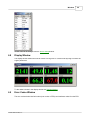
8 Display Window
................................................................................................................................... 40
9 Error Codes ...................................................................................................................................
Window
40
10 ECU Information
...................................................................................................................................
Window
41
Part VII Commands
1 Download
42
................................................................................................................................... 42
2 Clear DTCs ................................................................................................................................... 42
3 Set Readiness
................................................................................................................................... 42
4 Updating KPro
...................................................................................................................................
firmware
43
5 Check for Updates
................................................................................................................................... 43
Part VIII Reference
1 Sensors
................................................................................................................................... 43
RPM
VSS
MAP
CLV
TPS
CAM
CAMCMD
INJ
DUTY
IGN
IAT
ECT
AF
AFCMD
S TRIM
L TRIM
Fuel Status
K Retard
K Level
K Thres
© 2003-2004 Hondata, Inc.
43
.......................................................................................................................................................... 44
.......................................................................................................................................................... 44
.......................................................................................................................................................... 44
.......................................................................................................................................................... 44
.......................................................................................................................................................... 45
.......................................................................................................................................................... 45
.......................................................................................................................................................... 45
.......................................................................................................................................................... 45
.......................................................................................................................................................... 45
.......................................................................................................................................................... 45
.......................................................................................................................................................... 45
.......................................................................................................................................................... 45
.......................................................................................................................................................... 46
.......................................................................................................................................................... 46
.......................................................................................................................................................... 46
.......................................................................................................................................................... 46
.......................................................................................................................................................... 46
.......................................................................................................................................................... 46
.......................................................................................................................................................... 46
.......................................................................................................................................................... 47
III
Hondata K-Series Programmable ECU
K Count
PA
BAT
ELD
PTANK
RVSLCK
BKSW
ACSW
ACCL
SCS
EPS
FLR
VTP
VTS
FANC
MIL
.......................................................................................................................................................... 47
.......................................................................................................................................................... 47
.......................................................................................................................................................... 47
.......................................................................................................................................................... 47
.......................................................................................................................................................... 47
.......................................................................................................................................................... 47
.......................................................................................................................................................... 47
.......................................................................................................................................................... 47
.......................................................................................................................................................... 47
.......................................................................................................................................................... 48
.......................................................................................................................................................... 48
.......................................................................................................................................................... 48
.......................................................................................................................................................... 48
.......................................................................................................................................................... 48
.......................................................................................................................................................... 48
.......................................................................................................................................................... 48
2 ECU Connectors
................................................................................................................................... 48
3 Retrieving DTCs
................................................................................................................................... 49
Part IX Troubleshooting
50
1 USB troubleshooting
................................................................................................................................... 50
2 Programmer...................................................................................................................................
troubleshooting
53
Index
55
© 2003-2004 Hondata, Inc.
Introduction
1
Introduction
1.1
Introduction to the K-Series Programmable ECU
4
Congratulations on purchasing your Hondata K-Series Programmable ECU. With proper care and
feeding it will provide hours of entertainment for the whole family. Note: Only feed the ECU as much as
it can eat in a 3 minute period.
The Hondata K-Series Programmable ECU consists of three components:
· ECU - the Honda ECU.
· KPro - a electronic board which fits inside the Honda ECU which allows the ECU to be reprogrammed plus adds datalogging functions.
· KManager - Windows software which interfaces with KPro.
Hondata, Inc.
386 Beech Ave
Unit B-2
Torrance, CA 90501
Tel: 310-782-8278
World Wide Web Site: http://www.hondata.com
© Hondata, Inc., 2003-2004
Hondata is not affiliated with Honda Motor Co. Windows is a trademark of Microsoft Corp.
1.2
Features
Hondata K-Series Programmable ECU features:
·
·
·
·
·
·
·
·
·
·
·
·
·
Plug in replacement of factory ECU.
High speed USB interface.
Editable fuel, ignition and cam angle tables.
Fuel trim, including individual cylinders.
Expanded fuel, ignition and cam angle tables for forced induction.
Alternate MAP sensor support.
Rev limiter control.
Engine protection from over boost and over temperature.
Adjustment for different sized injectors, with overall fuel trim and individual cylinder fuel trim.
VTEC set as a VTEC window.
Nitrous control.
Closed loop control.
Idle speed adjustment.
Note: Not all features are available for all models.
© 2003-2004 Hondata, Inc.
5
1.3
Hondata K-Series Programmable ECU
What's new in this version
Change History
V1.1.3
· Fixed non-stock MAP sensor information not saving in calibration.
· Added TSX, Si JRSC and Si Greddy calibrations.
V1.1.2
· Fixed division by zero error when switching off the engine and datalogging.
· Removed target A/F atmospheric pressure compensation at full engine load.
V1.1.1
· Initialized high boost portion of calibrations.
· Fixed 16-28 lb boost portion of base and Civic calibrations not being displayed.
V1.1
· Added support for non-stock MAP sensors.
· Improved the upload algorithm which detects which parts of the ECU memory needs to be re-written
during an upload.
· Fixed knock threshold not datalogging for PND ECUs
V1.0.18
· Fixed help->contents crashing application
· Change boost cut so that it is removed when engine speed drops below 2000 rpm or the throttle is
released (previously rpm and MAP was used)
· Removed used options (some units, display size).
· Added engine overheating protection.
· Added the option to disable iVTEC
· Prevent the use of % symbols in the notes field.
· Validate air temperature compensation when loading calibration.
· Added two cybernation calibrations.
V1.0.17
· Make sure update file is created in the correct directory
· Force the use of a comma as the list separator and dot as the decimal point to prevent European
language users from generating an error when loading calibrations.
· Fixed problem in display window where injector duration would not display
· Fixed missing help file problem
· Fixed idle speed glitch.
V1.0.16
· Update ECU type every upload
V1.0.15
· Remove fuel correction when switching to open loop under high load
· Added boost cut
· Added European Civic Type R support
· Added stock K24 Accord calibration (using PNF Civic Si ECU)
V1.0.14
· Improved datalogging speed
· Added an error message for errors while uploading
© 2003-2004 Hondata, Inc.
Introduction
6
V1.0.13
· Added the option to disable the secondary intake runner control on base RSX (PND) ECUs
· Added support for the US Civic Si
· Fixed problem with highlight area on 2D ignition tables while datalogging
· Added the command the export datalog files.
· Fixed problem where current field in parameters window was not saved before upload.
V1.0.12
· Added support for the US base RSX
· Add Close command to the Datalog menu
· Fixed use of numeric keypad, negative and period keys in tables.
· Changed hot keys for datalog and record to F10 & F9 respectively.
V1.0.11
· Altered intake air temperature compensation
· Added nitrous status to datalog sensors
V1.0.10
· Fixed injector duration showing over 100% duty cycle
· Added new pressure unit to display inches vacuum and psi boost
· Added launch rev limiter
V1.0.9
· Added download calibration command.
· Changed nitrous control so that fuel may be removed and ignition advanced (for alcohol injection).
· Stop datalogging / recording when ignition switched off.
· Fixed index out of range error.
· Added calibration description.
V1.0.8
· Added more help.
· Added the option to disable the fuel over-run cutoff delay.
V1.0.7
· Fixed idle speed not saving in calibration
· Fixed disable P0134 not saving in calibration
· Added calibrations
V1.0.6
· Fixed datalog resolution problem
V1.0.5
· Added the option to disable error P0134
· Fixed problem where OBDII scan tools could not communicate
V1.0.4.13
· Updated JRSC 440 & 550 calibrations and Rev Hard calibration
· Corrected nitrous input & output descriptions
V1.0.3.12
· Added the option to switch to open loop above a certain MAP
V1.0.2.11
· Added the option to disable error P1167
· Added the option to flash the MIL when knock detected
© 2003-2004 Hondata, Inc.
7
Hondata K-Series Programmable ECU
V1.0.1.10
· Added undo.
· Added some calibrations.
· Added option for the table to follow VTEC and the cam angle.
V1.0.0.9
· Added context sensitive help
· Fixed internet update
V1.0.0.8
· Added drag & drop to open calibration files.
· Added association to open calibration and recordings from Windows Explorer.
· Added Create Forced Induction Tables form.
· Changed calibration extension from .kcd to .kal
· Enabled fuel system status
V1.0.0.6
· Added option to disable VTEC oil pressure
1.4
Software License Agreement
IMPORTANT: This License Agreement is a legal agreement between You and Hondata. PLEASE
READ THE TERMS AND CONDITIONS OF THIS LICENSE AGREEMENT CAREFULLY BEFORE
USING THE SOFTWARE. BY INSTALLING, COPYING OR OTHERWISE USING THE SOFTWARE,
YOU ARE CONFIRMING YOUR ACCEPTANCE OF THE SOFTWARE AND AGREEING TO
BECOME BOUND BY THE TERMS OF THIS AGREEMENT. IF YOU DO NOT AGREE, DO NOT
INSTALL OR USE THE PRODUCT.
Definitions. "Hondata" means Hondata, Inc. "You"/"Your" means you and/or your company.
"Software" means the product provided to You, which includes computer software and may include
associated media, printed materials, and "online" or electronic documentation.
Ownership. The Software is owned and copyrighted by Hondata and/or its licensors and is protected
by copyright laws and international copyright treaties, as well as other intellectual property laws and
treaties. THE SOFTWARE IS LICENSED, NOT SOLD. Your license confers no title or ownership in
the Software and is not a sale of any rights in the Software. You agree that aspects of the licensed
materials, including the specific design and structure of individual programs, constitute trade secrets
and/or copyrighted material of Hondata. You agree not to disclose, provide, or otherwise make
available such trade secrets or copyrighted material in any form to any third party without the prior
written consent of Hondata. You agree to implement reasonable security measures to protect such
trade secrets and copyrighted material. Title to Software and documentation shall remain solely with
Hondata.
Disclaimer of Warranty. The Software is provided on an "AS IS" basis, without warranty of any kind,
including, without limitation, the warranties of merchantability, fitness for a particular purpose and noninfringement. The entire risk as to the quality and performance of the Software is borne by You. Should
the Software prove defective, You, not Hondata or its licensors, assume the entire cost of any service
and repair. If the Software is intended to link to, extract content from or otherwise integrate with a third
party service, Hondata makes no representation or warranty that Your particular use of the Software is
or will continue to be authorized by law in Your jurisdiction or that the third party service will continue to
be available to You. In no event shall Hondata's or its suppliers' liability to You, whether in contract, tort
(including negligence), or otherwise, exceed the price paid by You. The foregoing limitations shall apply
even if the above-stated warranty fails of its essential purpose. This disclaimer of warranty constitutes
an essential part of the agreement. SOME STATES DO NOT ALLOW LIMITATION OR EXCLUSION
OF LIABILITY FOR CONSEQUENTIAL OR INCIDENTAL DAMAGES.
© 2003-2004 Hondata, Inc.
Introduction
8
Limitation of liability. UNDER NO CIRCUMSTANCES AND UNDER NO LEGAL THEORY, TORT,
CONTRACT, OR OTHERWISE, SHALL HONDATA OR ITS LICENSORS BE LIABLE TO YOU OR
ANY OTHER PERSON FOR ANY INDIRECT, SPECIAL, PUNITIVE, INCIDENTAL, OR
CONSEQUENTIAL DAMAGES OF ANY CHARACTER INCLUDING, WITHOUT LIMITATION,
DAMAGES FOR WORK STOPPAGE, COMPUTER FAILURE OR LOSS OF REVENUES, PROFITS,
GOODWILL, USE, DATA OR OTHER INTANGIBLE OR ECONOMIC LOSSES. IN NO EVENT WILL
HONDATA OR ITS LICENSORS BE LIABLE FOR ANY DAMAGES IN EXCESS OF THE AMOUNT
PAID TO LICENSE THE SOFTWARE, EVEN IF YOU OR ANY OTHER PARTY SHALL HAVE
INFORMED HONDATA OR ITS LICENSORS OF THE POSSIBILITY OF SUCH DAMAGES, OR FOR
ANY CLAIM. NO CLAIM, REGARDLESS OF FORM, MAY BE MADE OR ACTION BROUGHT BY
YOU MORE THAN ONE YEAR AFTER THE BASIS FOR THE CLAIM BECOMES KNOWN TO THE
PARTY ASSERTING IT. EXCEPT AS SPECIFIED IN THIS WARRANTY, ALL EXPRESS OR IMPLIED
CONDITIONS, REPRESENTATIONS, AND WARRANTIES INCLUDING, WITHOUT LIMITATION,
ANY IMPLIED WARRANTY OF MERCHANTABILITY, FITNESS FOR A PARTICULAR PURPOSE,
NONINFRINGEMENT OR ARISING FROM A COURSE OF DEALING, USAGE, OR TRADE
PRACTICE, ARE HEREBY EXCLUDED TO THE EXTENT ALLOWED BY APPLICABLE LAW. IN NO
EVENT WILL HONDATA OR ITS SUPPLIERS BE LIABLE FOR ANY LOST REVENUE, PROFIT, OR
DATA, OR FOR SPECIAL, INDIRECT, CONSEQUENTIAL, INCIDENTAL, OR PUNITIVE DAMAGES
HOWEVER CAUSED AND REGARDLESS OF THE THEORY OF LIABILITY ARISING OUT OF THE
USE OF OR INABILITY TO USE THE SOFTWARE EVEN IF HONDATA OR ITS SUPPLIERS HAVE
BEEN ADVISED OF THE POSSIBILITY OF SUCH DAMAGES.
Grant of License. Hondata grants You a non-exclusive and non-transferable license to use the
Software in object code form on a single central processing unit owned or leased by You. You may
make one (1) archival copy of the Software provided You affix to such copy all copyright, confidentiality,
and proprietary notices that appear on the original.
Restricted use. You agree to use reasonable efforts to prevent unauthorized copying of the Software.
You may not disable any licensing or control features of the Software or allow the Software to be used
with such features disabled. You may not share, rent, or lease Your right to use the Software. You may
not modify, sublicense, copy, rent, sell, distribute or transfer any part of the Software except as
provided in this Agreement. You may not reverse engineer, decompile, translate, create derivative
works, decipher, decrypt, disassemble, or otherwise convert the Software to a more human-readable
form for any reason. You will return or destroy all copies of the Software and generated content (if
applicable) if and when Your right to use it ends. You may not use the Software for any purpose that is
unlawful.
Reverse Engineering. EXCEPT AS EXPRESSLY AUTHORIZED ABOVE, YOU SHALL NOT: COPY,
IN WHOLE OR IN PART, SOFTWARE OR DOCUMENTATION; MODIFY THE SOFTWARE;
REVERSE COMPILE OR REVERSE ASSEMBLE ALL OR ANY PORTION OF THE SOFTWARE; OR
RENT, LEASE, DISTRIBUTE, SELL, OR CREATE DERIVATIVE WORKS OF THE SOFTWARE.
Applicable Software. The above warranty DOES NOT apply to any beta software, any software made
available for testing or demonstration purposes, any temporary software modules or any software for
which Hondata does not receive a license fee. All such software products are provided AS IS without
any warranty whatsoever.
Termination. This License is effective until terminated. You may terminate this License at any time by
destroying all copies of Software including any documentation. This License will terminate immediately
without notice from Hondata if You fails to comply with any provision of this License. Upon termination,
You must destroy all copies of Software.
Export Regulation. Software, including technical data, is subject to U.S. export control laws, including
the U.S. Export Administration Act and its associated regulations, and may be subject to export or
import regulations in other countries. You agrees to comply strictly with all such regulations and
acknowledges that it has the responsibility to obtain licenses to export, re-export, or import Software.
© 2003-2004 Hondata, Inc.
9
Hondata K-Series Programmable ECU
Applicable Law. This License shall be governed by and construed in accordance with the laws of the
State of California, United States of America, as if performed wholly within the state and without giving
effect to the principles of conflict of law. If any portion hereof is found to be void or unenforceable, the
remaining provisions of this License shall remain in full force and effect. This License constitutes the
entire License between the parties with respect to the use of the Software.
Governing Language. Any translation of this License is done for local requirements and in the event
of a dispute between the English and any non-English versions, the English version of this License
shall govern.
Entire Agreement. This license constitutes the entire agreement between the parties relating to the
Software and supersedes any proposal or prior agreement, oral or written, and any other
communication relating to the subject matter of this license. Any conflict between the terms of this
License Agreement and any Purchase Order, invoice, or representation shall be resolved in favour of
the terms of this License Agreement. In the event that any clause or portion of any such clause is
declared invalid for any reason, such finding shall not affect the enforceability of the remaining portions
of this License and the unenforceable clause shall be severed from this license. Any amendment to
this agreement must be in writing and signed by both parties.
Additional Software. This license applies to updates, upgrades, plug-ins and any other additions to
the original Software provided by Hondata, unless Hondata provides other terms along with the
additional software.
© 2003-2004 Hondata, Inc.
Introduction
2
Installation
2.1
Installation overview
10
Important: Please install the KManager software before plugging in the ECU
Engine Ground
It is very important that the ground from the wiring harness to the engine (G101) makes good electrical
contact with the cylinder head. Otherwise the return path for the sensors, ignition and VTEC may be
through the ECU case to the vehicle body, which may damage the ECU and/or programmable board
inside the ECU.
The recommended position for the engine ground is on the stud attached to the cylinder head. While
the stock location on the intake manifold will usually work without problems, the stud on the cylinder
head provides a better electrical connection.
Installation
Please follow the installation steps in the correct order.
1.
2.
3.
4.
Install the KManager software from the installation CD (see Installing KManager software).
Install the USB drivers.
Install the ECU (see Installing the ECU in the Vehicle).
Upload a base calibration into the ECU (see Uploading calibrations to the ECU).
If you have any problems refer to USB troubleshooting
2.2
Installing KManager software
To install the KManager software insert the CD into the CD drive. Installation should start automatically;
if it does not, use Window Explorer to open the CD drive and double-click on the installation
executable.
© 2003-2004 Hondata, Inc.
11
Hondata K-Series Programmable ECU
Once KManager is installed it is recommended that you check the Hondata website for updates using
the Check for Updates command.
It is only recommended to have one copy of KManager on a PC at a time (i.e. do not keep multiple
versions of KManager on a PC).
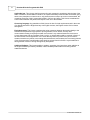
2.3
Installing USB drivers
Important: Please install the KManager software before plugging in the ECU
1.
Plug the USB cable into the ECU and laptop. The ECU does not need to be in the vehicle at this
point. When you plug in the USB cable the following message should be displayed on the
Windows Taskbar.
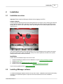
2.
Windows will automatically run the Found New Hardware Wizard. Windows will prompt for USB
drivers. Click on Install from a list of specific location.
3.
Windows will prompt for USB drivers. Enter the path to the KManager software (normally this is
C:\Program Files\KManager.
© 2003-2004 Hondata, Inc.
Installation
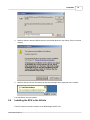
4.
Windows will warn that the USB drivers have not passed Windows Logo testing. Click on Continue
Anyway.
5.
Windows will copy drivers, and shortly the following message will be displayed on the Taskbar.
The USB drivers are now installed.
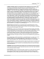
2.4
12
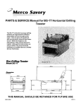
Installing the ECU in the Vehicle
The ECU mounts in the stock location for the RSX/Integra and EP Civic.
© 2003-2004 Hondata, Inc.
13
Hondata K-Series Programmable ECU
It is easiest to plug the USB cable into the ECU before you install the ECU as the USB connector is
hidden once the ECU is install into some vehicles. Take care not to place any strain on the USB
connector and the circuit board inside the ECU.
Take care not to short the metal shield around the USB connector to the ECU case or chassis ground.
It is not necessary to ground the case of the ECU.
Immobilizer
If the immobilizer light on the dash blinks (green key symbol) then you may to re-enable the
immobilizer.
If the ECU does not match and vehicle (key and immobilizer transponder) then it is possible to disable
the flashing immobilizer symbol simply by unplugging the immobilizer transponder (located on the
ignition switch barrel).
© 2003-2004 Hondata, Inc.
Installation
3
Calibrations
3.1
Introduction to calibrations
14
A calibration is a set of parameters and settings to 'tune' an ECU to a particular engine combination. It
contains all the information which you can edit from KManager, including fuel, ignition & cam angles
tables plus the parameters. It is independent from the 'program' code used in the ECU.
Calibration files have the extension .kal. When KManager is installed, this file extension is associated
with KManager so that you mat open a calibration by double-clicking on it. If the file extension
association does not work then open the Settings dialog and check 'Associate calibration and datalog
files with KManager'.
3.2
Uploading calibrations to the ECU
Uploading a calibration to the ECU will transfer the calibration from the laptop to the ECU. The vehicle
ignition must be switched on while uploading. To upload a calibration use Online->Upload or Ctrl+U.
The first time a calibration is uploaded to the ECU it will take approximately 1 minute. Subsequent
uploads are performed differentially and take from 3 seconds - 15 seconds to upload.
3.3
Upgrading calibration files
Because calibrations are stored independently from the program code for the ECU, program changes
for the ECU are automatically applied whenever when you upload a calibration to an ECU.
To update a calibration in an ECU:
1. Load the calibration file into KManager
2. Upload the calibration into the ECU. Any ECU program changes are automatically applied.
4
Datalogging
4.1
Introduction to datalogging
KManager can datalog from the ECU when connected to the ECU and the vehicle ignition is switched
on. There is no internal storage inside the ECU so a laptop must be connected to the ECU in order to
datalog. Note that some sensors are not datalogged if the engine is not running.
KManager uses frames to datalog. A frame is like a snapshot of all sensor values taken at one point in
time. The number of datalog frames and datalog length is shown below the menu bar in the main
window.
Datalog files have the extension .kdl, and normally are associated with KManager so that doubleclicking on a datalog file will open the recording in KManager. If the file extension association does not
work then open the Settings dialog and check 'Associate calibration and datalog files with KManager'.
4.2
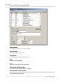
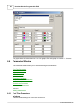
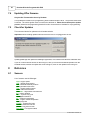
Sensor Setup
This window allows you to customise sensor settings.
© 2003-2004 Hondata, Inc.
15
Hondata K-Series Programmable ECU
Abbreviation
This is the name shown in the sensors window.
Display Name
This name is shown in print-outs.
Description
Further explains the function of the sensor.
Unit
Shows the sensor data type.
Unit
Allows you to specify the unit for the sensor.
Display Min & Display Max
The minimum and maximum values for graphing.
Warning Min & Warning Max
Sets a warning range for the display window. Sensor values will turn from green to red when the value
goes outside the warning range.
© 2003-2004 Hondata, Inc.
Datalogging
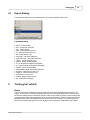
4.3
16
Export Datalog
The command exports the current datalog file in a comma separated value format.
Fields and Units
·
·
·
·
·
·
·
·
·
·
·
·
·
·
·
·
·
·
·
5
frame - frame number
time - frame time (seconds)
rpm - engine speed
map - manifold pressure (bar)
clv - calculated load value (%)
tps - throttle position (%)
camangle - cam angle (degrees)
targetcamangle - cam angle (degrees)
injector - injector duration (ms)
ignition - ignition timing (degrees)
ta - air temperature (degrees centigrade)
tw - water temperature (degrees centigrade)
lambda - air/fuel ratio (lambda)
targetlambda -target air/fuel ratio (lambda)
shorterm - short term fuel trim (%)
longterm - long term fuel trim (%)
knockcount - knock count
voltage - battery voltage (volts)
eld - electrical load (amps)
Tuning your vehicle
Basics
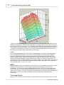
First it is important to understand how the Honda ECU determines the appropriate settings for the
engine. The Honda ECU uses the speed/density method of calculating these values. The ECU uses
the intake manifold pressure and engine speed to index lookup tables for ignition, fuel and cam angle
(amongst other things). Other parameters such as coolant temperature, battery voltage and intake air
temperature are used to compensate the table lookup values for the engine. To tune the engine we
alter the main tables (fuel, ignition and cam angle) to suit the particular configuration of the engine.
© 2003-2004 Hondata, Inc.
17
Hondata K-Series Programmable ECU
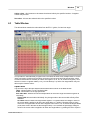
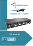
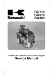
A typical fuel table is shown above. The indices used are rpm (along the bottom) and intake manifold
pressure (along the side). The ECU uses interpolation to calculate valves from the table which do not
fall exactly on a row or column index. e.g. if an ignition table contains 20 degrees advance at 2000 rpm
and 10 degrees advance at 3000 rpm, when the engine rpm is 2500 rpm the ignition advance will be
15 degrees. The interpolation actually occurs in two dimensions (engine speed and engine load) or
three dimensions (engine speed, engine load and cam angle).
VTEC
VTEC is one mechanism Honda uses to achieve good emissions, fuel economy and engine power
from a small displacement engine. The function of VTEC (variable valve timing and lift electronic
control) is to provide two distinct camshaft profiles which are switched electro-hydraulically. The
smaller camshaft profile is called the low-speed cam; the larger the high speed cam. The camshaft
profiles are switched depending on engine rpm and load, usually from 2500 rpm to 6500 rpm. The
main effect on tuning of VTEC is that there are usually two copies of every major table - one for the low
speed camshaft, one for the high speed camshaft. Another tuning consideration is the point at which
VTEC switches (see Tuning the VTEC point).
iVTEC
iVTEC ('intelligent' VTEC) is a combination of VTEC and VTC. VTC (variable timing control) is another
mechanism used by Honda to increase engine output which decreasing emissions and fuel
consumption. VTC controls the intake camshaft advance. Unlike VTEC VTC is not a simple on/off
control, rather the ECU controls the intake camshaft advance over a range of 60 crank degrees in
steps of 1/4 of a degree. The effect on tuning of VTC is that there are 6 copies of each major table - for
cam advance 0, 10, 20, 30, 40 and 50 degrees. In effect this makes the major tables three
dimensional.
The Tuning Process
Because of VTC, tuning the K-Series engine is a little different from tuning any other engine. The best
© 2003-2004 Hondata, Inc.
Tuning your vehicle
18
process is:
· Tune the fuel then ignition for every cam angle for the low speed cam (see Tuning fuel tables and
Tuning ignition tables).
· Tune the fuel then ignition for every cam angle for the high speed cam.
· Tune the cam angle tables (see Tuning cam angle tables).
· Set the VTEC point (see Tuning the VTEC point).
5.1
Tuning cam angle tables
Introduction
The cam angle is the intake cam advance measured in crank degrees. The allowable cam angle range
is from 0 to 50 degrees.
The intake cam is positioned by an electro-hydraulic mechanism, which uses feedback from the intake
cam position to alter the position of a solenoid which in turn rotates the intake cam inside the cam
sprocket. Because of the design of the mechanism there is a delay between setting the cam position in
the ECU, and the cam physically rotating to this position. This delay is around 0.1 seconds per 10
degrees of rotation.
Warning:
With Honda cams there is a physical stop limiting cam advance to prevent valve to valve contact and
valve to piston contact. With after market cams it is up to the manufacturer to ensure that the cam
lobes are positioned so that valve to valve and valve to piston contact is not possible. Because the cam
control mechanism uses a closed-loop feedback system, limiting the cam position in the ECU will not
guarantee that the cam position will not exceed what is set in the ECU. Because of this all cams must
have a physical stop to prevent valve contact.
Tuning Guidelines
In short, the better the breathing of the engine; intake, cams and exhaust, the greater the cam advance
needed. There is no situation in which best overall performance is achieved by fixing the cam angle to
just one setting or using manual cam adjustment wheels for the intake cam. There may be benefits to
fitting and adjusting the exhaust camshaft angle, which is not under computer control.
· With a naturally aspirated engine the cam advance should be set to maximum just after VTEC
engagement until about 6500-7000 rpm. From 7000 rpm (where the cam advance should be near 50
degrees) to redline the cam is retarded back around 25 degrees. This procedure is correct for all
commercially available after market cams at the date of release of this software, but camshafts
which are substantially different from a Honda camshaft may require different settings.
· With a supercharged engine the cam advance needs to be set to maximum (50 degrees or more)
throughout the rev range, with only a 10 degrees or so retard above 7000 rpm.
· With a turbocharger engine the cam advance needs to be less than stock. This is because a
turbocharger generates much more exhaust back pressure than a naturally aspirated or
supercharged configuration. The higher the back pressure the more cam retard is needed. With
small turbos and stock catalytic converters you may need to retard the cam fully to 0 degrees at
8000 rpm
Procedure
· Set the VTEC point high (6500 or 7000) rpm. Only dyno the low speed cam.
· Set both the high speed and low speed cam angles to zero. Tune the fuel and ignition tables for this
cam angle (this is necessary because the engines runs at 0 cam advance when cold and for the first
10 seconds of operation).
· Set both cam angle tables to 10 degrees, then 20 degrees and so on up to 50 degrees, and tune the
ignition and fuel tables for this cam angle.
· Perform dyno runs at 0, 10, 20, 30, 40 and 50 degrees. This will give you with 6 dyno curves with
different cam angles. Set the cam angles in the cam angle map to those which give you maximum
© 2003-2004 Hondata, Inc.
19
Hondata K-Series Programmable ECU
power then re-dyno. The power curve you get should be a maximum of all the 6 individual dyno runs
you have just done.
· Now we need to "bracket" the composite cam angle map we have just created. Add 5 degrees to the
cam angle map and re-dyno. Subtract 5 degrees and re-dyno. This will verify you have an optimum
cam angle map. You will probably find a few RPM points, particularly where the cam is changing
angle, that need a little modification to make more power. If you wish you can then bracket the
resultant power curve by dynoing with plus or minus 2 degrees cam angle change. The power
change at this degree of cam angle change is likely to be about 1 – 1.5 hp on a naturally aspirated
engine.
· Now set the VTEC point low (3000 rpm) and repeat the above procedure for the high speed cam.
Cam Angle at VTEC
If the cam position tables require the camshaft to rotate a large amount at VTEC (e.g. from 20 degrees
on the low speed cam angle table to 45 degrees on the high speed cam angle table) you may lose
power for 500-700 rpm after VTEC activates, as the cam rotates into the correct position. The best
method is to start advancing the intake cam in the low speed cam angle table before the VTEC point,
so the cam has to rotate less once VTEC activates. This usually means sacrificing a few hp just before
VTEC point to gain hp after the cams switch. When this is done right the characteristic VTEC change
in sound is greatly reduced.
Part Throttle Cam Angle
This applies to the portions of the cam angle table below full naturally aspirates load (column 7 and
less).
· At idle and low rpm (below 100 rpm) set the cam angle to 0 or 5 degrees.
· At cruising rpm and load (columns 2 - 7 and 1500 - 4500 rpm) set the cam angle to around 30
degrees. The EGR effect of the extra camshaft overlap will reduce emissions and improve fuel
economy at cruise.
· Above normal cruise rpm set the cam angle to the same value as under full load. This will smooth
out gearshifts as the cam shaft will not start to rotate back to zero during the gearshift.
Hints
· Remember that the cam cannot rotate instantaneously. It takes about 0.1 seconds to rotate 10
degrees. Cam angle changes should not be great over a small rpm interval.
· The intake cam is locked at 0 degrees for 10 seconds after a hot start. Let the engine run for at least
10 seconds after starting the engine before performing a dyno run.
5.2
Tuning fuel tables
Warning:
A lean air/fuel condition will damage the engine. Make sure that you monitor the air/fuel ratio at all
times, and abort any dyno run if the air/fuel ratio becomes too lean.
Tuning Fuel at full load
It it necessary to use and lambda meter (air/fuel gauge) to tune to fuel tables. Certain K-Series engines
utilise and wide-band oxygen sensor which is useful for tuning, otherwise most dynos are equipped
with a lambda meter. It is best to tune so that the air/fuel plot are fairly flat.
Tuning Fuel at part throttle
To tune the fuel for part throttle the aim is to get the air/fuel ratio so that the engine will run correctly in
closed loop. Normally the closed loop air/fuel ratio will center around the stoichiometric air/fuel ratio of
14.7:1, so it is best to tune the fuel tables up to column 7 to 14.7:1.
© 2003-2004 Hondata, Inc.
Tuning your vehicle
5.3
20
Tuning ignition tables
Warning:
Excessive ignition advance will damage the engine. The combustion pressure and load on the engine
(especially bearing stress) increase dramatically if the engine is over-advanced. Do not believe the
fallacy that 'more is better' for ignition advance. Too little ignition advance can also damage the engine
by increasing the exhaust gas temperature, especially with turbo-charged engines. Do not rely on the
knock sensor to retard the ignition timing if the engine detonates.
The Knock Sensor
One important tool in tuning ignition advance is the knock sensor. This is a sensitive microphone
located on the engine block which the ECU uses to determine when the engine is knocking (or
pinging). A useful datalog variable is the knock count, which in incremented every time the ECU hears
knock. The knock count is reset every time the engine is started. When performing dyno runs monitor
the knock count after every run (and preferably during the run). It is normally for the ECU to sense a
small amount of knock at the VTEC point, usually 2 times. If the knock count is more than this then it is
very likely that the engine is knocking, which should be fixed as soon as possible.
Tuning Ignition Advance at full load
The best way to determine the correct ignition advance at full load is by using a dyno. Generally for
naturally aspirated engines it is safe to set the advance near to maximum power, with the aim being to
run the least amount of timing possible. A good procedure is to tune for maximum power then retard
the timing until you just start to lose power (around 1 hp). At all times monitor engine knock to make
sure there is no detonation (even for a naturally aspirated engine). If pinging it audible or the ECU
shows that the engine is knocking (e.g. the knock count is increasing) then it is advisable to abort the
dyno run, retard timing/add fuel, and restart the run.
With forced induction engines it is important not to over-advance the ignition, otherwise the engine will
be damaged in only a few seconds. Use conservative ignition settings, monitor the knock sensor and
abort any dyno run if the engine shows signs of knock, pinging or detonation.
Tuning Ignition Advance at part throttle
Tuning ignition advance at part throttle is more difficult than full throttle because it is difficult to
accurately determine the correct settings. In general the default calibrations are suitable for part
throttle, otherwise an EGT gauge can be used to determine the best ignition advance.
5.4
Tuning the VTEC point
Warning:
· Do not set the VTEC point too low as the engine will lose oil pressure and possibly damage the
engine. It is not recommended to set the VTEC point below 2000 rpm.
· Do not set the VTEC point too high as the high speed cam rocker arm may float on the lost motion
assembly, damaging the valve spring retainers. It is not recommended to set the VTEC point over
6500 rpm.
The determine the best VTEC point perform two dyno runs, one with VTEC set low (e.g. 3000 rpm)
and the other run with VTEC set high (e.g. 6500 rpm). Set the VTEC point to the intersection of the
high speed cam and the low speed cam. Generally if there is a sudden increase in engine output
immediately after the cams switch then lower VTEC. Conversely if there is a sudden dip in engine
output then raise the VTEC point. Since the VTEC point will be at the intersection of the low speed and
high speed cam torque curves, it is normal for the torque to dip around the VTEC point.
© 2003-2004 Hondata, Inc.
21
Hondata K-Series Programmable ECU
6
Windows
6.1
Settings
The window allows you the alter general KManager parameters and settings.
General Settings
Table change for increase and decrease keys - this sets the amount by while the ignition and fuel
tables are altered when the increase and decrease keys are used to alter a selection in the
Table Window The Cam Angle is always altered by 1 degree.
Rounding - currently unused.
File association - check this to associate calibration and datalogging files with KManager. If you
associate files with
Display Settings
© 2003-2004 Hondata, Inc.
Windows
This tab contains settings for the display window.
Size - this is the height of the fields in the display window, measured in pixels.
Sensors - this selects which sensors are shown in the display window.
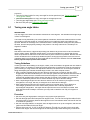
6.2
Main Window
The main window contains a number of child windows which allow you to edit the current ECU
calibration and show and datalogging and graphing.
© 2003-2004 Hondata, Inc.
22
23
Hondata K-Series Programmable ECU
The Status Bar (at the bottom of the main window) contains:
On Line / Off Line - Shows if the laptop is connected to the ECU via the USB cable.
Ignition On / Ignition Off - Shows the state of the vehicle ignition.
Datalog - displays Datalog when the ECU is being datalogged.
Record - displays Record when the ECU is being recorded.
Modified flag - displays Modified when the calibration has been edited but not saved.
6.2.1
Undo History
The Undo History window shows a list of editing activities performed on the current calibration.
© 2003-2004 Hondata, Inc.
Windows
24
This window is for informative purposes only.
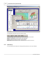
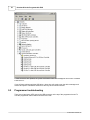
6.2.2
New Calibration
The New Calibration window is a way of creating a new calibration from a pre-defined calibration.
To load a calibration select a calibration from the list and select 'OK', or double-click on the calibration.
Note: All the calibrations were tuned and tested by Hondata on vehicle setups are shown in the
description column. These calibrations make a good starting point but usually require further tuning to
run perfectly.
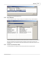
6.2.3
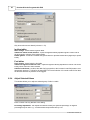
Create Forced Induction Tables
This window allows you to initialize the forced induction parts of the fuel & ignition tables.
© 2003-2004 Hondata, Inc.
25
Hondata K-Series Programmable ECU
Only boost columns are altered (columns 11-13).
Ignition tables
Don't change - doesn't alter the ignition table.
Initialise to lowest normal advance - copies the highest naturally aspirated ignition column into all
the boost portion columns of the ignition tables.
Retard ignition - as above but retards the ignition based on specified retard value (degrees per pound
boost).
Fuel tables
Don't change - doesn't alter the fuel table.
Initialise to highest normal fuel value - copies the highest naturally aspirated fuel column into all the
boost portion columns of the fuel tables.
Add fuel under boost - as above but adds fuel in proportion to the increase in manifold pressure over
atmospheric pressure. To allow for the lower BSFC for forced induction it is normal to add for fuel than
the absolute increase in pressure would suggest.
6.2.4
Adjust Selected Values
This window allows you to adjust a selected group of cells in a table.
Enter a number into only one box in this dialog.
Percentage adjustment - this adjusts the selected cells by the specified percentage. A negative
percentage may be used. e.g. -10 will decrease the specified cells by 10%.
© 2003-2004 Hondata, Inc.
Windows
26
Add to values - this increases or decreases the selected cells by the specified number. A negative
number may be used.
Set values - this sets the selected cells to the specified number.
6.3
Table Window
The table window contains the main tables from the ECU - ignition, fuel and cam angle.
It is important to understand that for Ignition and Fuel tables the ECU stores multiple tables for various
intake cam angles. Ignition and Fuel tables are broken into low-speed and high-speed tables, which
are then broken down into 6 tables (for intake cam angles of 0, 10, 20, 30, 40 and 50 degrees). Thus
there are a total of 12 Ignition tables (2 x 6), 12 Fuel tables (2 x 6) and 2 Cam Angle tables. Only one
table may be viewed at a time.
Option Area
The area at the top of the table window selects which table is shown in the table window.
Table - selects Ignition, Fuel of Cam Angle table.
VTEC - selects either low or high speed cam.
Cam Table Edit - determines how the multiple tables for each cam angle are edited for Ignition &
Fuel tables.
Single Table edits each table individually. Any change made to the current table will only effect
that table.
All Tables edits all related cam angle tables together. For Ignition tables the change in value for
the current table is applied to all other cam angle tables. e.g. adding 2 degrees timing to some
cells in the 30 degree table will also add 2 degrees times to the 0, 10, 20, 40 and 50 degree tables
(to the same cells in the table as the 30 degree table). For fuel tables the percentage change in
value for the current value is applied to all other cam angle tables. e.g. adding 4% fuel to a potion
© 2003-2004 Hondata, Inc.
27
Hondata K-Series Programmable ECU
on the 20 degree fuel table will add 4% fuel to the 0, 10, 30, 40 and 50 degree tables. Note that for
fuel tables the other tables are always altered by a percentage change, even if the current fuel
table is not changed by a percentage.
Cam Angle - selects the cam angle table
Graph Type - 2D or 3D graph.
Grid View
The area on the left of the table window shows a numerical representation of the current table. Cell
values may be altered either by clicking on the cell and entering a value, or using the arrow keys to
move the current selection (blue square) onto a cell, then entering a value. Cells may be selected by
using the mouse to allow more than one cell to be altered at a time. All the cells in the table may be
select by using Ctrl+A. If multiple cells are selected, the Adjust Selected Values window (Ctrl+J) may
be used to alter the selected cells. Ctrl+I and Ctrl+D will increase and decrease the selected cells.
Graph View
The right side of the table window contains a 2D or 3D representation of the current table. Mapping
points on the 2D graph may be altered by clicking on the rectangles and dragging up or down. On the
3D graph clicking will select an area on the Grid View.
6.4
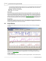
Graph Window
The graph window displays sensor values either while recording, or while reviewing a datalogged
recording.
The graph may be scrolled using the scroll bar at the bottom of the window. A cursor may be
positioned on the screen by left-clicking on the graph window. This will change the sensor values
displayed in the Sensors Window.
Graph Templates
The graph window displays sensors based on pre-defined graph templates. These templates specify
© 2003-2004 Hondata, Inc.
Windows
28
the number of sub-graphs on the graph window, and the sensors in each sub-graph. For more
information see the Graph Templates Window
Graph Menu
Additional graph functions may be accessed either from the Graph menu, or by right clicking on the
graph window.
Zoom In - zooms the graph in centered on the cursor.
Zoom Out - zooms the graph out centered on the cursor.
Zoom Full - shows the full recording on the graph window.
Next Template - selects the next graph template.
Previous Template - selects the previous graph template.
Define Templates - opens the Graph Templates Window
6.5
Graph Templates
This window allows you to define and edit graph templates, which are used in the Graph Window This
allows you to switch between many different display configurations for the graph window quickly.
© 2003-2004 Hondata, Inc.
29
Hondata K-Series Programmable ECU
The graph window is broken down into 1 to 4 sub-graphs. Each sub-graph can contain 1 - 4 sensors.
6.6
Parameters Window
The Parameters Window allows you to edit the following ECU parameters:
Fuel Trim Parameters
Rev Limit Parameters
MAP Parameters
VTEC Parameters
Misc Parameters
Nitrous Parameters
Protection Parameters
Compensation Table Parameters
Notes Parameters
Closed Loop Parameters
Idle Parameters
Knock Sensor Parameters
Also see:
Adding a MAP Sensor
6.6.1
Fuel Trim Parameters
Injectors
This tab contains settings for injector size and fuel trim.
© 2003-2004 Hondata, Inc.
Windows
30
Changing the injector size will automatically compensate the fuel tables for the rating of the injector
(but not for the specific characteristics of the injector). Also the cranking fuel is compensated based on
the injector size.
Fuel Trim
The overall fuel trim is an additional compensation applied evenly to the main fuel tables. The cranking
fuel trim is applied when starting the engine.
Note that the injector size will automatically reduce the overall fuel and cranking fuel even if the trims
are set to zero.
Cylinder Fuel Trim
By changing the cylinder fuel trim it is possible to add or remove fuel for individual cylinders. Note that
the injector duration as datalogged is the duration for injector #1. Changing the fuel trim for cylinder #1
will result in the datalogging showing the duration for cylinder #1, not the rest of the cylinders.
Warning: Do not set the cylinder fuel trim from reading the spark plugs. The only reliable way to set
the fuelling for individual cylinders is using EGTs.
6.6.2
Rev Limit Parameters
Note: All rev limiters operate via fuel cut.
Overall Rev Limiter
This is the main engine speed limiter value.
Do not increase the rev limiter unless you are sure all the components of the engine will withstand the
greater stress.
Launch Rev Limiter
The launch rev limiter operates when the car is stationary. When the clutch is released and the car
© 2003-2004 Hondata, Inc.
31
Hondata K-Series Programmable ECU
starts to move the launch rev limit is removed.
6.6.3
MAP Parameters
This tab contains MAP Sensor parameters. Also see MAP Sensor Installation
Warning : Exceeding the MAP sensor upper pressure limit will result in the engine running lean.
Warning : Setting the boost limit beyond the MAP sensor upper pressure limit will result in the boost
limiter not functioning.
The MAP (manifold absolute pressure) sensor reads air pressure in the intake manifold to determine
engine load. It is the primary sensor in determining fuel, ignition and other requirements of the engine.
The stock MAP sensor can read pressure to approximately 1.8 bar (11.4 lbs boost pressure). Beyond
this value a replacement MAP sensor is necessary. Any sized linear 5V MAP sensor can used - which
is virtually any MAP sensor.
Tab Parameters
MAP Sensor Selection
Either the stock MAP sensor or an alternate sensor can be used. If the stock MAP sensor is selected
then the stock voltage to pressure conversion is used - you do not need to enter anything in the
Voltage to Pressure conversion section of the tab.
Quick Select
Selects from a number of pre-set voltage to pressure conversion parameters. If the MAP sensor you
are using is not listed then you will need to enter a custom conversion.
© 2003-2004 Hondata, Inc.
Windows
32
Scalar
The scalar (multiplication value) for the MAP sensor voltage to pressure conversion. For more
information see scalar & offset.
Offset
The offset for the MAP sensor voltage to pressure conversion. For more information see scalar &
offset.
Full Scale Values
This calculates the full scale pressure readings at in mbar and lbs boost. Note that these values are
calculated at 5V and may not be achievable due to differences in supply voltage from the ECU. See
Boost Limit for more information.
Atmospheric Pressure Values
This calculates the expected voltage at standard atmospheric pressure (1013.2 mbar). Note that not
all MAP sensors will report atmospheric pressure under key-on-engine-off conditions.
Scalar & Offset
A MAP sensor converts a pressure reading into a voltage output. There is a relationship between
output voltage and pressure which determines the pressure range of the MAP sensor. This
relationship should be linear (otherwise the MAP sensor is poor quality) and therefore can be
described using a linear equation.
The scalar and offset describe the pressure / voltage equation. These values may be determined by
measuring the voltage output from the MAP sensor and plotting on a graph, or from the
specifications of the MAP sensor.
If you do not know the scalar of offset for a MAP sensor then please do not guess.
Boost Limit
The boost limit operates when the manifold pressure exceeds a pre-set value. The value must be
within the range of pressure that the MAP sensor can read, with a margin for production tolerances
on the ECU sensor output voltage and MAP sensor. You must not assume that a 5V MAP sensor
will reach 5V output at maximum pressure. e.g. the boost limit is set to 11.3 lbs for a stock MAP
sensor, which equates to an output voltage of 4.96 V from the MAP sensor. This is too close to the
maximum output of the MAP sensor for reliable triggering of the boost cut (the MAP sensor might
never exceed 4.9 V for instance). It is recommended that a 1 lb or 0.2V margin is left between the
boost cut and MAP sensor maximum pressure reading.
5 Bar MAP Sensors
While any linear MAP sensor is supported, the fuel,ignition and cam angle tables are only currently
mapped to 28 lbs. For MAP sensors greater than 3 Bar absolute a future software release will allow
the column pressure index to be altered to allow higher values. The number of columns will not
change.
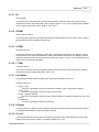
6.6.3.1
Adding a MAP Sensor
Wiring in a replacement MAP Sensor
If wiring in a replacement MAP sensor take great care to ensure that the wiring is correct before
© 2003-2004 Hondata, Inc.
33
Hondata K-Series Programmable ECU
applying power. Most MAP sensors will not tolerate reversed polarity and will burn out very quickly.
To save cutting the wiring harness it is recommended to use a replacement MAP sensor with a
Honda type connector. Failing that, use a MAP sensor with wiring pigtail and wire the MAP sensor in
parallel with the stock MAP connector (only plug in one MAP sensor at a time!). This allows easy
diagnostics of any problems by allowing the stock MAP sensor to be hooked up at any time. It is not
recommended to cut the stock MAP sensor connector off.
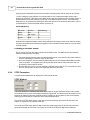
Stock MAP Wiring
Wire Color
Function
MAP Marking
yel/red
VCC
V
grn/red
MAP Signal
O
grn/wht
GND
G
Determine the replacement MAP sensor wiring and splice the wiring into the factor harness. Double
check all connectors before switching the ignition on as most MAP sensors will burn out if you make
a wiring mistake.
Plumbing in the MAP sensor
Run a vacuum line from the intake manifold for the MAP sensor. The MAP sensor must read the
intake manifold pressure accurately.
· For supercharged vehicles make sure that the MAP sensor is connected to the intake manifold
after the supercharger, otherwise it will not see boost.
· Do not be tempted to use the cold air bypass fitting close to the cylinder head between number
2 and 3 cylinders. This supplies air to the injector tips while cold for better emissions and is a
poor place to read manifold vacuum.
· Run a single vacuum line from the manifold to the MAP sensor with no 'Ts' or branches to other
devices, such as blow of valves, boost gauges and boost controllers.
6.6.4
VTEC Parameters
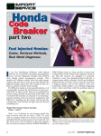
This tab contains parameters for setting the VTEC point & window.
VTEC Window
The VTEC window is a variable VTEC switch point based on engine speed and engine load. Usually
you want the VTEC point to move higher with lighter engine load. The above screen shot shows VTEC
switching at 5000 rpm when the manifold pressure is 89 kPa or above (which is close to full throttle),
reducing in a linear fashion to 5800 rpm at 25 kPa manifold pressure.
Do not set the VTEC switch point too low as there will be insufficient oil pressure for the rest of the
engine. As a guide do not go below 2000 rpm.
Do not set the VTEC switch point too high as the high speed rocker arm will float on the lost motion
spring and damage the valve train. As a guide do not set the VTEC point higher than 6500 rpm.
© 2003-2004 Hondata, Inc.
Windows
34
VTEC Options
For JDM engines and JDM ECUs disable the VTEC oil pressure sensor.
Disable VTC for engines with locked camshafts.
Secondary Intake Runner Options
The option is only available for engines with secondary intake runners. Disable the secondary intake
runners if the intake manifold is replaced with a single path manifold (e.g. a supercharger manifold).
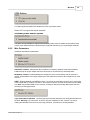
6.6.5
Misc Parameters
Additional miscellaneous parameters.
Immobilizer enabled - Sets whether the immobilizer is enabled or disabled. Keep the immobilizer
enabled except for engine-swaps where the vehicle has no immobilizer key and transponder.
Multiplexor enabled - Enables/disables the multiplexor, which communicates with the rest of the
vehicle. Only disable this for engine-swaps where the vehicle does not have the multiplexor unit in the
fuse box.
OBDII - Enables/disables most OBDII functions. To remove the secondary o2 sensor error (from using
a race header with no catalytic converter or secondary o2 sensor) clear the check mark from the OBDII
box. Note: Only disable OBDII for race vehicles, as doing so will prevent many OBDII tests and error
checking from being performed.
Copy Protect ECU Calibration - checking this will prevent the calibration from being downloaded from
the ECU. Warning: If you check this, be sure to save the calibration to disk, as there is no way of
reading the calibration from the ECU once copy protected. This feature is currently disabled.
© 2003-2004 Hondata, Inc.
35
6.6.6
Hondata K-Series Programmable ECU
Nitrous Parameters
These parameters allow the ECU to control the use of nitrous oxide or water/alcohol injection.
Enable Nitrous Control - enables the control on nitrous.
Arming Input - specifies which ECU pin is used to arm nitrous.
Output Control - specifies which ECU pin controls the nitrous solenoid. Important: the ECU cannot
sink enough current directly to control a solenoid. A relay must be used between the ECU and solenoid
to prevent damage to the ECU.
Conditions - specifies the conditions which must be met before the output is switched on.
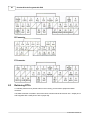
Fuel & Ignition - specifies changes to fuel and ignition when nitrous is activated.
The maximum retard is 40 degrees, and the ignition timing can be retard to a maximum of 10 degrees
BTDC.
Do not make nitrous changes without using a wideband lambda meter to determine the correct air/fuel
ratio. As a general guide, the following extra fuel is necessary:
Nitrous Jet Fuel Value
0.24
200
0.32
350
0.47
850
© 2003-2004 Hondata, Inc.
Windows
36
With nitrous control it is possible to remove fuel and/or advance ignition timing by using negative
values. This is useful when using water/alcohol injection.
The above example will remove fuel and advance the ignition timing by 4 degrees when activated.
6.6.7
Protection Parameters
Engine protection parameters.
Boost Cut
The boost cut is designed to prevent engine damage from over-boosting. It has two settings - a cold
boost limit and a hot boost limit.
The cold boost cut operates below the cold/hot transition temperature; the hot boost cut operates
above the transition temperature. In this way the engine can be protected from boost when not fully
warmed up.
When the boost cut is triggered fuel is immediately cut to the engine, as per the main rev limiter. When
either engine speed falls below 2000 rpm or the throttle is released, the rev limiter is removed.
With a stock MAP sensor the maximum level for a boost cut is 10.5 lbs. This must be less than the
maximum range of the MAP sensor (~11.3 lbs) so that the MAP sensor is capable of sensing when the
manifold pressure exceeds the boost cut limit.
To disable the boost cut set the units to kPa and enter a value of 0 for both hot and cold boost cuts.
Overheating Protection
Overheating protection attempts to protect your engine from damage via overheating. Note that it will
not prevent the cause of the overheating in the first place!
© 2003-2004 Hondata, Inc.
37
Hondata K-Series Programmable ECU
Overheating temperature is the temperature above which the engine is deemed to be overheating.
Set this above the normal operating temperature of the engine.
If the engine temperature exceeds the overheating temperature, then one or more of the following
actions are taken:
Add extra fuel - this enrichens the mixture in an attempt to cool the engine. Note that this will not
usually cure the overheating condition.
Generate P0217 error code (engine overheating) - will generate an error code which can be read
with KManager or an OBDII scan tool.
Illuminate the MIL - switches on the MIL (check engine light) when the engine over-heats.
Go into 4000 rpm limp mode (optional) - this will rev limit the engine to 4000 rpm. This is not
recommended for race applications.
Warn driver by cyclically applying a brief rev limiter (optional) - this will briefly rev limit at around a
1 second interval. The rev limiter is very brief and the driver will feel this as a slight hesitation,
especially under full power. Idle and low load running is not affected.
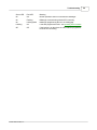
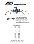
6.6.8
Compensation Table Parameters
Air Temperature Compensation
The air temperature compensation tables determine how the ECU alters the amount of fuel delivered
based on the intake air temperature. There are two air intake temperature compensation tables; one
for low load and idling conditions and another for medium to high load. As a guide the low load table is
used below 3500 rpm at light manifold pressure, 2000 rpm at medium manifold pressure and 1000 rpm
at high manifold pressure.
The compensation tables have two rows - temperature and correction factor. The temperature is
measured in degrees Fahrenheit. A higher correction factor will increase the amount of fuel delivered,
a lower correction factor will decrease the amount of fuel delivered.
Theory of Air Temperature Compensation
Air density decreases with increasing temperature, so the corresponding amount of fuel needs to be
less with hotter intake air temperatures. The calculation for the change in density (and theoretical
change in fuel) is :
Density ratio = Temp 1
© 2003-2004 Hondata, Inc.
Windows
38
Temp 2
Both temperatures are measured in degrees Rankin (= degrees F + 459.67) or degrees Kelvin (=
degrees C + 273)
e.g. if the air intake temperature changes from 80 degrees to 100 degrees, the air density change is 80
+ 460 / 100 + 460 = 0.964 = -3.6 %
However in practice the fuel requirements of the engine are different from that calculated from the
above air density calculation. In practice the decrease in engine fuel requirements is less than what the
change in air density would suggest. What happens is that the speed of sound increases as the air
temperature increases, and the engine will flow slightly better. Generally the air temperature
compensation needs to be slightly less than half that calculated from the change in air density.
Tuning the Air Temperature Compensation Tables
The engine behaves differently at light load than high load, which is why there are two tables to tune
the air temperature compensation. Generally at idle and light load the engine requires almost no
reduction of fuel at higher air intake temperatures.
For the medium/high load table a rough guide of 1 % reduction in fuel for every 10 degrees F increase
in air intake temperature. At high air intake temperatures it is usually best to not reduce the fuel as
much, in order to cool the engine with a richer mixture.
6.6.9
Notes Parameters
This allows you to enter notes about the calibration.
6.6.10 Closed Loop Parameters
These parameters control closed loop operation.
Disable closed loop while tuning. Otherwise the ECU will adjust the air/fuel ratio resulting in an
inconsistent air/fuel ratio.
Disable P1167 and P0134 DTCs for race vehicles without a primary oxygen sensor.
© 2003-2004 Hondata, Inc.
39
Hondata K-Series Programmable ECU
Maximum Map for closed loop - this determines the maximum engine load for closed loop.
Disable fuel over-run cutoff delay - this disables the 0.5 second delay between closing the throttle
and the fuel injectors being shut down under over-run conditions. Disable this if you experience a
hesitating while shifting with large injectors or see the short term fuel trim go sharply negative while
shifting.
6.6.11 Idle Parameters
Idle speed parameters.
Sets the hot idle speed.
6.6.12 Knock Sensor Parameters
Knock sensor parameters.
Always enable the knock sensor.
Flashing the MIL (check engine light) when the ECU detects knock will help alert you if the engine is
knocking.
6.7
Sensor Window
The sensors window displays a list of sensors, which are updating when datalogging or while
displaying a recording.
© 2003-2004 Hondata, Inc.
Windows
40
Sensor units can be changed from the Sensor Setup window.
6.8
Display Window
The display window shows some sensor values in a large font. It is useful while dynoing to monitor the
engine parameters.
To alter what is shown in the display window see Settings Window
6.9
Error Codes Window
The error codes window lists fault codes (error codes or DTCs) and readiness codes from the ECU.
© 2003-2004 Hondata, Inc.
41
Hondata K-Series Programmable ECU
Fault Codes
Fault codes are error codes from the Honda ECU, and usually indicate a problem with a sensor or
wiring in the vehicle. The Honda ECU does not store temporary DTCs so only stored DTCs are shown.
Fault codes are stored once the ignition is switched off. Fault codes may be cleared using the
Clear DTCs command.
Readiness Codes
Readiness codes indicate which OBDII tests the ECU supports and the status of those tests. The
Honda ECU does not support all tests. Readiness codes are reset to 'Not Complete' when the
Clear DTCs command is used. Readiness codes may be marked as 'Complete' using the
Set Readiness command.
6.10
ECU Information Window
The ECU information windows shows information from the ECU.
© 2003-2004 Hondata, Inc.
Windows
42
Hardware
The hardware version and serial number from the Hondata programmer inside the ECU.
Firmware
The firmware version and status from the Hondata programmer inside the ECU.
ECU
The ECU type, software version and information on the security status.
Statistics
Information on the number of reads, writes and errors from the Hondata programmer inside the ECU.
7
Commands
7.1
Download
The download command will download the current calibration from the ECU.
7.2
Clear DTCs
The Clear DTCs command clears any fault codes from the ECU. Also see Error Codes Window.
7.3
Set Readiness
The Set Readiness command sets all readiness codes to 'Complete'. Also see Error Codes Window.
© 2003-2004 Hondata, Inc.
43
7.4
Hondata K-Series Programmable ECU
Updating KPro firmware
Only do this if instructed to do so by Hondata.
This updates the firmware in the programming board located inside the ECU. The process takes about
2 minutes. The vehicle ignition does not need to be switched on. Please do not interrupt the update
process, otherwise the programming board will need to be sent back to Hondata for re-programming.
7.5
Check for Updates
This command checks for updates on the Hondata website.
Important: When installing updates make sure that the ECU is not plugged into the PC.
Updating KManager will update the KManager application, ECU software and the base calibration files.
If you do not have Internet access on the tuning PC, then you will need to download updates from the
Hondata website, transfer the update files to the tuning PC, then run the update on the tuning PC.
8
Reference
8.1
Sensors
List of sensors used in KManager:
RPM - Engine speed
VSS - Vehicle speed sensor
MAP - Manifold absolute pressure
CLV - Calculated load value
TPS - Throttle position sensor
CAM - Intake cam advance
CAMCMD - Target intake cam advance
INJ - Injector duration
DUTY - Injector duty cycle
IGN - Ignition advance
IAT - Intake air temperature
ECT - Engine coolant temperature
AF - Air/fuel ratio
AFCMD - Target air/fuel ratio
S.TRIM - Short term fuel trim
L.TRIM - Long term fuel trim
Fuel Status - Fuel system status
© 2003-2004 Hondata, Inc.
Reference
44
K Retard - Knock retard
K Level - Knock level
K Thres - Knock threshold
K Count - Knock count
PA - Atmospheric pressure
BAT - Battery voltage
ELD - Electrical load
PTANK - Fuel tank pressure
RVSLCK - Reverse lock solenoid
BKSW - Brake switch
ACSW - Air conditioning switch
ACCL - Air conditioning clutch
SCS - Service connector switch
EPS - Electric power steering
FLR - Fuel pump relay
VTP - VTEC pressure switch
VTS - VTEC spool valve
FANC - Radiator fan clutch
MIL - Malfunction indicator light
8.1.1
RPM
RPM is a measure of the engine speed in revolutions per minute calculated from the crank position
sensor.
Note that the RPM as displayed in KManager may be different from that shown on the tachometer. The
rpm calculated from the ECU is extremely accurate whereas most tachometers read 5-10 % over.
8.1.2
VSS
Vehicle Speed Sensor
VSS is a measure of the vehicle ground speed, calculated from the VSS sensor, which is located on
the transmission. Because the speed of the driven wheels is measured, wheel slip and wheel spin are
not compensated for.
8.1.3
MAP
Manifold Absolute Pressure
The MAP sensor measures the air pressure inside the intake manifold, after the throttle plate. On
supercharged vehicles it is important for the MAP sensor to read manifold pressure after the
supercharger.
8.1.4
CLV
Calculated Load Value
CLV is a measurement of engine load expressed as a percentage of maximum load. The sensor is
mainly for OBDII compatibility.
© 2003-2004 Hondata, Inc.
45
8.1.5
Hondata K-Series Programmable ECU
TPS
Throttle Position Sensor
The TPS measures the angle of the throttle plate. Is is mainly used for detecting idle and fail-safe
functions. The ECU mainly uses the MAP sensor when calculating engine load and fuel/ignition
settings.
8.1.6
CAM
Intake Camshaft Position
This is the intake camshaft position, measured in degrees of crankshaft rotation from a base position.
For the first 10 seconds after startup the intake will be locked in the zero (fully retarded) position.
8.1.7
CAMCMD
Intake camshaft command
This is the desired position for the intake camshaft, based on the cam advance table and engine
running conditions. Because the VTC mechanism is a closed loop feedback system, the actual intake
camshaft advance make lag the CAMCMD by 0.1 - 0.5 seconds.
8.1.8
INJ
Injector Duration
This is the injector duration for an injector, usually measured in milliseconds. The injector duration is
for #1 injector.
8.1.9
DUTY
This is the injector duty cycle. 100% means the injector is fully open (it never closed) and cannot
deliver any more fuel. The injector duration usually reaches it's maximum near peak power. Normally it
best to upgrade the injectors and/or the fuel system once the duty cycle reaches 80-85%
Remember that different driving conditions may place further demands on the fuel system from when
the engine was tested. e.g. colder weather will require more fuel from the injectors.
8.1.10 IGN
This is the ignition timing in degrees before top dead center.
8.1.11 IAT
Intake Air Temperature
This is the temperature of the air measured in the intake pipe. For forced induction it is recommended
to move the IAT so that it reads the temperature of the air after the supercharger or turbocharger. An
OBDI IAT is compatible with the K-Series ECU.
8.1.12 ECT
Engine Coolant Temperature
This is the engine coolant temperature as measured in the cylinder head.
© 2003-2004 Hondata, Inc.
Reference
46
8.1.13 AF
Air/Fuel Ratio
The air/fuel ratio is calculated from the stock lambda sensor. Note that JDM, USA and some other
vehicles have a semi-wide band sensor, with a range of approx 11.5:1 to 30:1 European spec vehicles
utilize a narrow band sensor, with a range of 14.5 - 14.9:1.
8.1.14 AFCMD
Air/Fuel ratio command
The air/fuel ratio command is the target air/fuel ratio as determined by the ECU. Note: The A/F CMD is
ignored when the ECU is operating in open loop.
8.1.15 S TRIM
Short term fuel trim
The short term fuel trim is used only in closed loop in modify the fuel delivery to the engine in order to
keep the air/fuel ratio close to stoichiometric, which is the optimum air/fuel ratio for catalytic converter
operation. Normally short term fuel trim should be within the range of -10% to +10%, otherwise the fuel
maps need to be tuned at part throttle.
8.1.16 L TRIM
Long term fuel trim
The long term fuel trim is the fuel adjustment based on the trend of the short term fuel trim. Normally
the long term fuel trim should range from -5% to +5%.
8.1.17 Fuel Status
The fuel system status shows the status of the closed loop operation of the ECU.
Common values are:
· Open - Cold
The ECU is operating in open loop because the engine is cold or has just been started.
· Open - Error
The ECU is operating in open loop due to an error code.
· Open - Driving Conditions
The ECU is operating in open loop due to driving conditions. Usually this is based on rpm, TPS
or MAP.
· Closed Loop
The ECU is operating normally in closed loop.
8.1.18 K Retard
This is the amount of ignition retard in degrees resulting from knock detected from the knock sensor or
a calculated retard based on expected driving conditions.
8.1.19 K Level
This is the processed noise from the knock sensor expressed in volts. Note that this is not the actual
voltage of the knock sensor, rather it is a relative voltage from 0 - 5V.
© 2003-2004 Hondata, Inc.
47
Hondata K-Series Programmable ECU
8.1.20 K Thres
This is the knock level voltage threshold where the ECU will consider the engine is knocking.
8.1.21 K Count
Knock Count
This knock count is a counter of any knock event which the ECU detects. The counter is reset each
time the ECU is reset, either by switching the ignition off or when a calibration is uploaded.
8.1.22 PA
Atmospheric Pressure
This shows the atmospheric pressure. The atmospheric pressure sensor is located inside the ECU.
8.1.23 BAT
Battery Voltage
This shows the battery voltage.
8.1.24 ELD
Electrical Load Detector
This shows the current draw on the battery/alternator from the vehicle.
8.1.25 PTANK
Fuel Tank Pressure
The fuel tank pressure for OBDII diagnostics.
8.1.26 RVSLCK
Reverse Lockup Solenoid
The reverse lockup output controls the reverse lock solenoid, located on the transmission. This
solenoid is switched above approximately 25 mph to prevent the shift mechanism from travelling to the
reverse gear plane. Only 6 speed transmissions have reverse lockout.
8.1.27 BKSW
Brake Switch
This shows the status of the brake switch.
8.1.28 ACSW
Air Conditioning Switch
This shows the status of the A/C switch. Note that the A/C switch is read via the multiplexor.
8.1.29 ACCL
Air Conditioning Clutch
This shows the status of the A/C clutch output. Normally the A/C clutch is switched from the A/C
© 2003-2004 Hondata, Inc.
Reference
48
switch, with a slight time delay to allow the engine to idle up before the A/C compressor is engaged.
8.1.30 SCS
Service Connector Switch
This shows the status of the service connector switch, which is activated by shorting two terminals on
the scan tool plug.
8.1.31 EPS
Electric Power Steering Switch
This shows the status of the electric power steering input.
8.1.32 FLR
Fuel Pump Relay
This shows the status of the fuel pump relay. Normally this is active for the first 2 seconds after the
ignition is switched on, or when the engine is running.
8.1.33 VTP
VTEC Pressure Switch
This shows the status of the VTEC pressure switch. Normally this will activate shortly after the VTEC
spool is switched on. Some JDM engines do not have the VTEC pressure switch.
8.1.34 VTS
VTEC Spool Valve
This shows the status of the VTEC spool valve. If switched on, oil is directed to the lock pins between
rocker arms to engage the high speed cam lobe.
8.1.35 FANC
Radiator Fan Clutch
This shows the status of the radiator fan clutch.
8.1.36 MIL
Malfunction Indicator Light or check engine light.
The MIL is located in the instrument cluster, and indicates that there is a problem with the engine, ECU
or wiring. It is normal for the MIL to illuminate for 2 seconds when the ignition is first switched on. By
shorting out a diagnostic connector it is possible to retrieve error codes from the ECU by counting
flashes from the MIL. With the programmable ECU it is easier to plug in a laptop and datalog the ECU
to retrieve the error codes.
8.2
ECU Connectors
All connectors are shown from the wire side of the female connector (i.e. looking at the ECU).
A Connector
© 2003-2004 Hondata, Inc.
49
Hondata K-Series Programmable ECU
B Connector
E Connector
8.3
Retrieving DTCs
To manually retrieve DTCs (trouble codes or error codes), you will need to jumper the OBDII
connector.
The OBDII connector is located in front of the centre console near the drivers foot well. Jumper pins 4
and 9 together with a small piece of wire or paper clip.
© 2003-2004 Hondata, Inc.
Reference
50
The MIL should start to flash out error codes. To interpret the MIL flashes, count the number of long
flashes and multiply by 10, then add the number of short flashes. The resulting DTC code can be
referenced in the Honda service manual.
9
Troubleshooting
9.1
USB troubleshooting
Background
When the ECU is connected to your PC for the first time, Windows detects the ECU and will ask for a
device driver. If Windows cannot find a driver for the device and you click the default "Finish" button or
click on "Disable the device," then Windows lists the ECU as a "USB Device" under "Other devices"
and Windows will never prompt you again to install the driver. If this happens then KManager will not
be able to communicate with the ECU.
When installing in Windows XP, Microsoft issues a warning that the software "has not passed
Windows Logo Testing to verify its compatibility with Windows XP." If you choose to stop installation
here, then Windows lists the ECU as a "USB Device" under "Universal Serial Bus Controllers."
© 2003-2004 Hondata, Inc.
51
Hondata K-Series Programmable ECU
Hints
· Most problems are caused by plugging in the ECU before installing the software. Unplug the ECU,
install the software, then follow the instructions below to update the drivers.
· Plug the ECU directly into the laptop/computer, not via a USB hub. Some USB hubs cannot supply
enough power for the ECU.
· Under Windows 2000, you must be logged in as Administrator or have sufficient privileges to install
device drivers.
Trouble Shooting Procedure
1.
Open the System Properties. To do this right click on My Computer and select Properties, or press
<Windows Key> and <Pause/Break>.
2.
Open the Device Manager.
3.
Click on the + to the left of Universal Serial Bus controllers to show the USB devices connected to
the computer. There should be an entry Hondata K-Series ECU.
© 2003-2004 Hondata, Inc.
Troubleshooting
4.
52
If there is a yellow icon next to the entry for Hondata K-Series ECU, then the USB drivers are not
properly installed. Right click in Hondata K-Series ECU and select Update Driver... Follow the
instructions as per installing the USB drivers.
© 2003-2004 Hondata, Inc.
53
Hondata K-Series Programmable ECU
5. After the drivers are updated, the yellow exclamation mark should disappear from next to 'Hondata
K-Series ECU'.
If you still have problems with the USB driver, reboot into safe mode, open the device manager and
remove all copies of 'Hondata K-Series ECU' and any other unknown devices.
9.2
Programmer troubleshooting
There are red and green LEDs next to the USB connector on the top of the programmer board. To
view the programmer status LEDs remove the ECU case.
© 2003-2004 Hondata, Inc.
Troubleshooting
Green LED
Red LED
Meaning
On
Off
Normal operation when not connected to KManager.
On
Flashing
KManager communicating with the ECU normally.
On
Flashing/Solid
KManager programming the ECU or datalogging.
Flashing
On
Fault with programmer board - see Updating KPro firmware
Off
Off
If the ignition is on then there is a fault with the programmer
board or ECU socketing.
© 2003-2004 Hondata, Inc.
54
55
Hondata K-Series Programmable ECU
Index
-FFeatures 4
Fuel status 46
Fuel tank pressure 47
Fuel Trim Parameters 29
-AA/C clutch 47
A/C switch 47
Adjust Selected Values 25
AF 46
AF CMD 46
AFCMD 43
Atmospheric pressure sensor
-GGraph Templates Window
Graph Window 27
47
-BBattery voltage 47
Brake switch 47
-CCalibrations 14
CAM 45
CAMCMD 45
Check For Updates 43
Clear DTCs 42
Closed Loop Parameters 38
CLV 44
Compensation Table Parameters 37
Create Forced Induction Tables 24
-D-
28
-IIAT 45
Idle Parameters 39
IGN 45
INJ 45
Installation 10
Installing KManager Software 10
Installing the ECU in the Vehicle 12
Installing USB drivers 11
Introduction 4
-KK Level 43
Knock count 47
Knock level 46
Knock retard 46
Knock Sensor Parameters
Knock threshold 47
Datalogging 14
Display Window 40
DTCs 49
DUTY 45
-L-
-E-
-M-
ECT 45
ECU Connectors 48
ECU Information Window 41
Electrical load 47
Error Codes Window 40
Main Window 22
MAP 44
MAP Parameters 31
Map Sensor Installation
Misc Parameters 34
Long term fuel trim
39
46
32
© 2003-2004 Hondata, Inc.
Index
-N-
-V-
New Calibration 24
Nitrous Parameters 35
Notes Parameters 38
VSS 44
VTEC Parameters
-W-
-P-
What's New
Parameters Window 29
Programmer Troubleshooting
Protection Parameters 36
-RRev Limit Parameters
Reverse lockup 47
RPM 44
30
-SSensor Setup 14
Sensors Window 39
Set Readiness 42
Settings 21
Short term fuel trim 46
Software License 7
-TTable Window 26
TPS 45
Tuning Cam Angle Tables 18
Tuning Fuel Tables 19
Tuning Ignition Tables 20
-UUndo History 23
Updating Firmware 43
Uploading Calibrations 14
USB troubleshooting 50
© 2003-2004 Hondata, Inc.
53
5
33
56