1
IVAC®598 Volumetric Pump
Directions For Use - English
s
Contents
Page
Introduction . . . . . . . . . . . . . . . . . . . . . . . . . . . . . . . . . . . . . . . . . . . . . . . . . . . . . . . . . . . . . . . . . . . . . . . . . . . . . . . . . . . . 2
About this Manual. . . . . . . . . . . . . . . . . . . . . . . . . . . . . . . . . . . . . . . . . . . . . . . . . . . . . . . . . . . . . . . . . . . . . . . . . . . . . . . 2
Features of the IVAC® 598 Volumetric Pump . . . . . . . . . . . . . . . . . . . . . . . . . . . . . . . . . . . . . . . . . . . . . . . . . . . . . . . 3
Controls and Indicators . . . . . . . . . . . . . . . . . . . . . . . . . . . . . . . . . . . . . . . . . . . . . . . . . . . . . . . . . . . . . . . . . . . . . . . . . . 4
Symbol Definitions . . . . . . . . . . . . . . . . . . . . . . . . . . . . . . . . . . . . . . . . . . . . . . . . . . . . . . . . . . . . . . . . . . . . . . . . . . . . . . 5
Operating Precautions . . . . . . . . . . . . . . . . . . . . . . . . . . . . . . . . . . . . . . . . . . . . . . . . . . . . . . . . . . . . . . . . . . . . . . . . . . .6
Getting Started . . . . . . . . . . . . . . . . . . . . . . . . . . . . . . . . . . . . . . . . . . . . . . . . . . . . . . . . . . . . . . . . . . . . . . . . . . . . . . . . . .8
Loading an Infusion Set . . . . . . . . . . . . . . . . . . . . . . . . . . . . . . . . . . . . . . . . . . . . . . . . . . . . . . . . . . . . . . . . . . . . . .9
Starting the Infusion . . . . . . . . . . . . . . . . . . . . . . . . . . . . . . . . . . . . . . . . . . . . . . . . . . . . . . . . . . . . . . . . . . . . . . . . .10
Basic Features . . . . . . . . . . . . . . . . . . . . . . . . . . . . . . . . . . . . . . . . . . . . . . . . . . . . . . . . . . . . . . . . . . . . . . . . . . . . . . . . . . .11
Alarm and Display Messages . . . . . . . . . . . . . . . . . . . . . . . . . . . . . . . . . . . . . . . . . . . . . . . . . . . . . . . . . . . . . . . . . . . . .12
Flow Sensor Operation (Optional). . . . . . . . . . . . . . . . . . . . . . . . . . . . . . . . . . . . . . . . . . . . . . . . . . . . . . . . . . . . . . . . .14
Specifications . . . . . . . . . . . . . . . . . . . . . . . . . . . . . . . . . . . . . . . . . . . . . . . . . . . . . . . . . . . . . . . . . . . . . . . . . . . . . . . . . . .15
Maintenance . . . . . . . . . . . . . . . . . . . . . . . . . . . . . . . . . . . . . . . . . . . . . . . . . . . . . . . . . . . . . . . . . . . . . . . . . . . . . . . . . . . .16
Cleaning and Storage . . . . . . . . . . . . . . . . . . . . . . . . . . . . . . . . . . . . . . . . . . . . . . . . . . . . . . . . . . . . . . . . . . . . . . . . . . . .17
Disposal. . . . . . . . . . . . . . . . . . . . . . . . . . . . . . . . . . . . . . . . . . . . . . . . . . . . . . . . . . . . . . . . . . . . . . . . . . . . . . . . . . . . . . . . .17
Infusion Sets . . . . . . . . . . . . . . . . . . . . . . . . . . . . . . . . . . . . . . . . . . . . . . . . . . . . . . . . . . . . . . . . . . . . . . . . . . . . . . . . . . . .18
Trumpet and Flow Rate Curves . . . . . . . . . . . . . . . . . . . . . . . . . . . . . . . . . . . . . . . . . . . . . . . . . . . . . . . . . . . . . . . . . . .19
Products and Spare Parts. . . . . . . . . . . . . . . . . . . . . . . . . . . . . . . . . . . . . . . . . . . . . . . . . . . . . . . . . . . . . . . . . . . . . . . . .21
Service Contacts . . . . . . . . . . . . . . . . . . . . . . . . . . . . . . . . . . . . . . . . . . . . . . . . . . . . . . . . . . . . . . . . . . . . . . . . . . . . . . . . .22
Warranty . . . . . . . . . . . . . . . . . . . . . . . . . . . . . . . . . . . . . . . . . . . . . . . . . . . . . . . . . . . . . . . . . . . . . . . . . . . . . . . . . . . . . . . .23
Index . . . . . . . . . . . . . . . . . . . . . . . . . . . . . . . . . . . . . . . . . . . . . . . . . . . . . . . . . . . . . . . . . . . . . . . . . . . . . . . . . . . . . . . . . . .24
1000DF00161 Issue 1
1/24
Introduction
The IVAC® 598 Volumetric Pump (hereinafter referred to as 'Pump') is a small lightweight volumetric infusion pump that provides accurate and
reliable infusions over a range of rates.
The IVAC® 598 Volumetric Pump automatically regulates the infusion rate of intravenous solutions. The microprocessor-based pump uses a linear peristaltic,
volume displacement mechanism to regulate fluid flow at the desired rate. The pump's many features include:
• Easy setup and operation:
Advisory prompts to assist in setup and operation.
Quick start mode.
Diagnostic alarm messages to simplify operation and troubleshooting.
Easy viewing of rate and volume-to-be-infused (VTBI) settings.
•
Wide range of infusion rates: 1 to 999 ml/h in 1 ml/h increments.
•
Volumetric rate entry.
•
Volume-to-be-infused capability with automatic switchover to the "keep vein open" (KVO) rate.
•
Integral ultrasonic air-in-line detection.
•
Detection of upstream/downstream occlusions.
•
Low occlusion pressures (nominal 6 to 8 psi).
•
Lightweight and portable with self-contained rechargeable battery.
•
Automatic flow shutoff with activation of audible and visible alarms.
•
Audible and visible low battery alert about one hour before battery alarm.
•
Optional flow sensor (Model 192).
•
Optional remote computer monitoring capability.
INTENDED USE:
The pump is designed to meet the infusion requirements within the operating environment specified in this Directions For Use (DFU)
including general wards, critical and intensive care, operating rooms and accident and emergency rooms.
This pump is suitable for use by appropriately trained clinicians or nurses. This pump can be used for Intravenous modes, supporting fluid
therapy, drug therapy, blood transfusions and parenteral nutrition.
About this Manual
The user must be thoroughly familiar with the pump described in this manual prior to use.
All illustrations used in this manual show typical settings and values which may be used in setting up the functions of the pump.
These settings and values are for illustrative use only. The complete range of settings and values are detailed in the specifications section.
1000DF00161 Issue 1
2/24
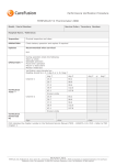
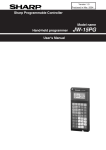
Features of the IVAC® 598 Volumetric Pump
Main Display
Display
Indicators
VTBI
VOL
ml
KVO
RATE
ml/hr
CLEAR
VOL
Keyboard
READ
VOL
Door
VOL
TO BE
INF
RUN/
HOLD
CAM Follower
Assembly
ON /
OFF
CAM Follower
Assembly Latch
AC power
Indicator
Model 598
Vo l u m e t r i c P u m p
Pole Clamp
Air-In-Line
Sensor
PE Connector
Test Connector Cover
AC Power
Connector
Flow Sensor
Connector
Fuse Holders
1000DF00161 Issue 1
3/24
Controls and Indicators
Controls:
Symbol
Description
ON/OFF switch - Press once to switch the pump ON. Press and hold down for approximately 3
seconds to switch the pump OFF.
RUN/HOLD switch - Starts and stops pump infusions. Silences/cancels alarms.
VOLUME TO BE INFUSED switch - Sets value of Volume To Be Infused (VTBI).
CLEAR VOLUME switch - Resets volume infused value to zero.
READ VOLUME switch - Displays volume infused value.
CHEVRON switches - Double chevrons/single chevrons for faster/slower increase or decrease
of infusion rate and volume values.
Indicators:
Symbol
Description
AC POWER indicator - When illuminated the pump is connected to an AC power supply and the
battery is being charged.
VTBI
The value displayed is the Volume To Be Infused.
KVO
The pump is infusing at the Keep Vein Open (KVO) rate of 5ml/h (or current rate, whichever is less).
VOL
The value displayed is the volume infused.
RATE
The value displayed is the current infusion rate.
ml
(Millilitres) The value displayed is the VTBI or volume infused value.
ml/hr
(Millilitres / hour) The value displayed is the infusion rate.
Infusion indicator. Three horizontal bars in the left-hand display position flash sequentially when the
pump is infusing.
Infusion indicator with Flow Sensor in use. Upper two horizontal bars convert to a square when a
drop is detected by the flow sensor in the drip chamber.
Flashing Display
When the pump is operating on battery power, the Display flashes on/off.
1000DF00161 Issue 1
4/24
Symbol Definitions
Labelling Symbols:
Symbol
w
x
IPX1
s
T
t
A
U
W
Description
Attention (Consult accompanying document)
Potential Equalisation (PE) Connector
Type CF applied part. (Degree of protection against electrical shock)
Protected against vertically falling drops of water
Device complies with the requirements of the EC Directive 93/42/EEC. Registered with the CE
Mark.
Date of Manufacture
Manufacturer
Important Information
Not for Municipal Waste
Fuse rating
1000DF00161 Issue 1
5/24
Operating Precautions
Infusion Sets
To ensure correct and accurate operation, only use Cardinal Health single use infusion sets described in this
Directions For Use.
It is recommended that infusion sets are changed according to the instructions in the 'Changing the
Infusion Set' section. Carefully read the Directions For Use supplied with the infusion set prior to use.
Use of non-specified infusion sets may impair the operation of the pump and the accuracy of the infusion.
When combining several apparatus and/or instruments with infusion sets and other tubing, for example via
a 3-way tap or multiple infusion, the performance of the pump may be affected and should be monitored
closely.
Uncontrolled flow may result if the infusion set is not properly isolated from the patient i.e. closing a tap in
the set or activating an in-line clamp / roller clamp.
The infusion set may be fitted with an in-line clamp, which can be used to occlude tubing in case it is
required to stop fluid flow.
The IVAC® 598 Volumetric Pump is a positive pressure pump, which should use infusion sets fitted with luer
lock fittings or equivalent locking connectors.
To infuse from a burette, close the roller clamp above the burette and open the clamp on the vent on top
of the burette.
Discard infusion set if the packaging is not intact or the protector cap is detached. Ensure sets are not
kinked as this may occlude the tubing.
Using Collapsible bags, Glass Bottles & Semi Rigid containers
It is recommended that the air vent be opened on the IVAC® 598 Volumetric Pump set if using glass bottles
or semi-rigid containers, to reduce the partial vacuum formed as the fluid is infused from the container.
This action will ensure the pump can maintain volumetric accuracy whilst the container empties. The action
of opening the air vent for semi-rigid containers should take place after the spiking of the container and
priming of the drip chamber.
Steps for the Collapsible bags
Steps for Semi-rigid containers
Follow steps 1 to 3 as shown for the
semi-rigid containers, however do not
open vent as in step 4, but prime the
set as per step 5. Ensure the bag outlet
is fully pierced before filling the drip
chamber.
2.
3.
4.
Spike the
container
Fill drip
chamber to
fill line
Open the air vent
to allow pressure
equalisation - ready
for infusion
5.
1.
Close the
roller clamp
Prime the set by
opening / closing the
roller clamp
Operating Environment
When using any infusion pump in conjunction with other pumps or devices requiring vascular access,
extra care is advised. Adverse delivery of medication or fluids can be caused by the substantial variation
in pressures created within the fluid channels of such pumps. Typical examples of those pumps are used
during dialysis, bypass or cardiac assist applications.
The pump is suitable for use in all establishments, other than domestic establishments and those directly
connected to the public low voltage power supply network that supplies buildings used for domestic
purposes.
This pump is not intended to be used in the presence of a flammable anaesthetic mixture with air or
oxygen or nitrous oxide.
The pumping pressure alarm system is not designed to provide protection against, or detection
of, extravasation or tissuing complications which can occur.
Operating Pressure
1000DF00161 Issue 1
6/24
Operating Precautions (Continued)
Alarm Conditions
Several alarm conditions detected by this pump will stop the infusion and generate visual and audible
alarms. Users must perform regular checks to ensure that the infusion is progressing correctly and no
alarms are operating.
Electromagnetic Compatibility and Interference
M
This pump is protected against the effects of external interference, including high energy radio frequency
emissions, magnetic fields and electrostatic discharge (for example, as generated by electrosurgical and
cauterising equipment, large motors, portable radios, cellular telephones etc.) and is designed to remain
safe when unreasonable levels of interference are encountered.
In some circumstances the pump may be affected by an electrostatic discharge through air at levels close
to or above 15kv; or by radio frequency radiation close to or above 10v/m. If the pump is affected by
this external interference the pump will remain in a safe mode; the pump will duly stop the infusion and
alert the user by generating a combination of visual and audible alarms. Should any encountered alarm
condition persist even after user intervention, it is recommended to replace that particular pump and
quarantine the pump for the attention of appropriately trained technical personnel.
This pump is a CISPR 11 Group 1 Class A device and uses RF energy only for its internal function in the normal
product offering. Therefore, its RF emissions are very low and are not likely to cause any interference with
the nearby electronic equipment. However, this pump emits a certain level of electromagnetic radiation
which is within the levels specified by IEC/EN60601-2-24 and IEC/EN60601-1-2. If the pump interacts with
other equipment, measures should be taken to minimise the effects, for instance by repositioning or
relocation.
Earth Conductor
The IVAC® 598 Volumetric Pump is a Class I device, therefore must be earthed when connected to an AC
power supply.
This pump also has an internal power source.
When connected to an external power source, a three-wire (Live, Neutral, Earth) supply must be used. If the
integrity of the external protective conductor on the AC power cable has been compromised, the pump
should be disconnected from the AC power source and operated utilising the internal battery.
Hazards
B
An explosion hazard exists if the pump is used in the presence of flammable anaesthetics.
Exercise care to locate the pump away from any such hazardous sources.
Dangerous Voltage: An electrical shock hazard exists if the pump’s casing is opened or removed.
Refer all servicing to qualified service personnel.
If this pump is dropped, subjected to excessive moisture, fluid spillage, humidity or high
temperature, or otherwise suspected to have been damaged, remove it from service for inspection
by a qualified service engineer. When transporting or storing the pump, use original packaging
where possible, and adhere to temperature, humidity and pressure ranges stated in the
Specifications section and on the outer packaging.
If this pump behaves abnormally, remove from service and contact a qualified service engineer.
Latex Content
The IVAC® 598 Volumetric Pump does not contain any latex.
1000DF00161 Issue 1
7/24
Getting Started
A
Before operating the pump read this Directions For Use (DFU) manual carefully.
Initial Set Up
1.
2.
Check that the pump is complete, undamaged and that the voltage rating specified on the label is compatible with your AC power
supply.
Items supplied are :
3.
IVAC® 598 Volumetric Pump
Directions For Use (CD)
AC Power Cable (as requested)
Protective Packaging
Connect the pump to the AC power supply for at least 6 hours to ensure that the internal battery is charged (verify that the AC Mains
indicator is lit).
A
The pump will automatically operate from its internal battery if the pump is switched on without being connected to the
power supply.
Should the pump fail to perform correctly, replace in its original protective packaging, where possible and contact a qualified
service engineer for investigation.
Pole Clamp Installation
A pole clamp is fitted to the rear of the pump and will provide secure fixing to vertical I.V. poles of a diameter between 12 and 26 mm.
Pole Clamp
1.
Unscrew the clamp to leave enough room for the size of the pole.
2.
Place pump around pole and tighten screw until the clamp is secured to the pole.
A
Never mount the pump such that the infusion stand becomes top heavy or
unstable.
1000DF00161 Issue 1
8/24
Getting Started (Continued) - Loading an Infusion Set
A
Ensure the appropriate infusion set for the fluid/drug to be infused has been selected.
Follow the instructions supplied with the individual infusion set.
Only use IVAC® 598 Volumetric Pump infusion sets, (Refer to 'Infusion Sets' section of the DFU)
Position the fluid container to avoid spillage onto the pump.
Ensure that the tubing is inserted completely into the top set retainer through to the tubing guide avoiding any slack.
Top set retainer
1. Prime the IV infusion set slowly and close the roller clamp.
2. Open the door.
3. Load the primed IV infusion set:
Open the latch
Load the upper tubing segment into the top set retainer
Insert lower tubing segment into the Air-In-Line Sensor
Close the latch, ensuring the set is enclosed
4. Close the door.
Primed IV
Infusion Set
5. Open the roller clamp. Ensure no fluid flows.
Lower Tubing Segment
1000DF00161 Issue 1
9/24
Latch
(shown open)
Air-In-Line Sensor
Getting Started (Continued) - Starting the Infusion
A
PRIME AND LOAD THE SET (Refer to 'Loading an Infusion Set')
1. Ensure the pump is connected to an AC power supply (also operates from battery).
2. Connect flow sensor, if required. (See 'Flow Sensor Operation')
3. Press the ON/OFF switch to power on the pump. The pump will power up and the rate and ml/hr indicators will light. The display will
show rate alternating with the rate value.
4. Use the chevron switches (I, J, L and K) to set or change the infusion rate.
5. To read the total infused volume press and hold the READ VOL switch. To clear the total infused volume, press and hold the CLEAR VOL
switch until the display reads 0000 (four zeros).
6. Press VOL TO BE INF if required. The VTBI and ml indicators will light. The display will alternate between VTBI and the current VTBI value.
When operating the pump without a flow sensor, a VTBI must be entered. This value is independent of any volume already infused. If the VTBI is at
0000 and the RUN/HOLD switch is pressed, the prompt VTBI will be displayed.
When operating the pump with a flow sensor, and a VTBI is not desired, press the L switch until OFF is displayed.
7. Use the chevron switches (I, J, L and K) to set VTBI.
8. Connect the infusion set to the patient access device.
9. Press RUN/HOLD to start infusion. The run indicator will appear when the pump mechanism begins to operate.
Changing the infusion rate
1. Press the RUN/HOLD switch to place the pump on hold.
2. Adjust rate by using the chevron switches.
3. Restart the pump by pressing the RUN/HOLD keys.
Clearing total volume infused
1. Press the RUN/HOLD switch to place the pump on hold.
2. Press and hold CLEAR VOL for 2 seconds, until display shows 0000.
3. Restart the pump by pressing the RUN/HOLD keys.
Changing the Volume To Be Infused
1. Press the RUN/HOLD switch to place the pump on hold.
2. Press the VOL TO BE INF switch.
3. Set new volume by pressing the chevron switches. OFF can also be selected when a flow sensor is in use, see Notes below.
4. Restart the pump by pressing the RUN/HOLD switch.
Notes:
1) Without a flow sensor in use, a VTBI value must be entered, otherwise, the pump displays VTBI when the pump is restarted.
2) With a flow sensor in use, a VTBI value isn't required and OFF can be selected if required.
1000DF00161 Issue 1
10/24
Basic Features
KVO (Keep Vein Open) Rate
When using a flow sensor and the solution container empties, the pump will alarm and FLO will be displayed.
When not using a flow sensor and the pump has counted down to zero from the preset volume-to-be-infused value, it automatically switches to a 5 ml/h
KVO rate, (or current rate, whichever is less), lights the KVO indicator, and produces two audible beeps every 5 seconds.
1. To exit the KVO mode, press the RUN/HOLD switch to place the pump on hold.
2. Press the VTBI switch. Set the VTBI to a value greater than zero.
3. Press RUN/HOLD to continue pump operation.
Changing the Infusion Set
1.
2.
3.
4.
5.
6.
Press RUN/HOLD switch to place the pump on hold.
Close in-line clamp and ensure the access to the patient is isolated.
Disconnect the infusion set from the patient.
Open pump door and remove infusion set from the pump and discard the set and fluid container according to hospital protocol.
Prepare the new infusion set, load infusion set into pump and close the door, see "Loading the Infusion Set".
Restart infusion, see "Getting Started".
A
When changing the infusion set or the fluid container use aseptic technique according to hospital protocol.
It is recommended that infusion sets are changed in accordance with the Directions For Use.
Carefully read the Directions For Use supplied with the infusion set prior to use.
The set change interval is 24 hours.
Changing the Fluid Container
1.
2.
3.
4.
5.
Press RUN/HOLD switch to place the pump on hold.
Remove bag spike on infusion set from empty / used container. Discard empty / used container according to hospital protocol.
Insert spike into new container.
Squeeze the drip chamber approximately half full or up to fill line (if the drip chamber is marked) with fluid.
Restart infusion, see "Getting Started".
A
When changing the infusion set or the fluid container use aseptic technique according to hospital protocol.
It is recommended that infusion sets are changed in accordance with the Directions For Use.
Carefully read the Directions For Use supplied with the infusion set prior to use.
SmartSite® Needle-Free System Instructions
SmartSite® Needle-Free Valve is designed to permit safe gravity flow and automated flow, injection and aspiration of fluids without the use of
needles by utilising luer lock and luer slip connectors.
A
Precautions:
Discard if packaging is not intact or protector caps are unattached.
If Needle-Free Valve is accessed by a needle in an emergency the valve will be damaged causing leakage. Replace Needle-Free
Valve immediately.
Needle-Free Valve contraindicated for blunt cannula system.
DO NOT leave slip luer syringes unattended.
DIRECTIONS - Use Aseptic Technique
1.
Prior to every access, swab top of Needle-Free Valve port with 70% Isopropyl alcohol (1-2
seconds) and allow to dry (approximately 30 seconds).
NOTE: Dry time is dependent on temperature, humidity, ventilation of the area.
2.
Prime valve port. If applicable, attach syringe to Needle-Free Valve port and aspirate minuscule
air bubbles.
3.
Replace every 72 hours for stand alone valves. However, if the valve is part of the set, then the set
change interval is as per the complete set or 100 activations which ever occurs first. For infusions
of blood, blood products or lipid emulsions replace infusion set every 24 hours.
NOTE: During use of Needle-Free Valve port, fluid may be observed between the housing and blue
piston. This fluid does not enter the fluid path and requires no action.
For product questions or needle-free valve educational materials contact your Cardinal
Health, Alaris® Products representative. The Center for Disease Control, Intravenous
Nurses Society (USA) and other organizations publish guidelines useful in developing
facility guidelines. Consult facility protocols.
1000DF00161 Issue 1
11/24
Alarm and Display Messages
If the pump sounds an alarm, note the alarm message and press the RUN/HOLD switch to place the pump on hold and silence the alarm.
Use the following guide to eliminate the cause of the alarm.
After correcting the condition, press the RUN/HOLD switch again to restart the infusion.
Displays Flashing Message with Audible Alarm
Display
Cause
Action
FLO
Upstream Occlusion
Check the tubing, clamp and container for probable causes and correct. (Repeated
alarms may indicate pump mechanism requires cleaning. Refer to the CLEANING
section of this DFU.)
FLO.1
Too few or no drops
The flow sensor has detected no or insufficient flow. Check tubing, clamp,
container and flow sensor for probable causes and correct.
FLO.2
Drip chamber problem.
Abnormal drops detected. Drip chamber fogged or overfilled. Shake drip
Flow sensor disconnected while pump in operation. chamber to clear sidewalls; reduce fluid level in drip chamber. Plug flow sensor
into connector on rear of instrument.
Possible faulty flow sensor.
FLO.3
Too many drops.
Flow detected in excess of the set rate. Flow detected while the pump is on hold
or in the start up mode.
Check that the set tubing is completely installed in the mechanism, that the
mechanism pinches off the tubing and that the drip chamber is not swinging
excessively or overfilled.
OCCL
Downstream occlusion.
Check for kinked tubing, clogged filter. (Repeated alarms may indicate pump
mechanism requires cleaning. Refer to the CLEANING section of this DFU.)
rELOAd
Set adapter improperly loaded into air detector.
Reload adapter into air detector. Press firmly until flush.
rELOAd
- - - - Air
Air detector senses air in tubing,
Ensure air detector is clean. Reload set adapter into air detector. Press firmly until
flush.
Air
Air detector senses air in tubing or set adapter Remove air according to hospital protocol. Ensure air detector is clean.
dislodged from air detector.
Door
Door opened during infusion or upon entering run Check set for proper installation. Close door and re-start pump.
mode.
BATT
Battery has insufficient charge to operate pump
HoLD
Two minutes have elapsed since pump was placed Press RUN/HOLD switch once to silence alarm, and again to restart pump. If switch
on hold or into start-up mode, or a switch may be is stuck, contact qualified service personnel.
stuck. If the pump is in start-up mode and on battery
power, it will automatically power-off if left in this
alarm for 3 minutes.
KVO005
or less
(two beeps)
Pump is in KVO mode.
Set the VTBI value to a non-zero value.
ERR
Possible pump malfunction.
Cycle power off, then on. If problem persists, do not use pump. Contact qualified
service personnel.
ERR n
Pump mechanism requires cleaning.
Refer to the CLEANING section of this DFU.
Momentary
display that
disappears
shortly after
power-up.
Pump has automatically shut off due to low battery
charge.
Plug the power cord into an AC outlet. The pump will be operable after several
seconds.
- or Set adapter improperly loaded into air detector.
(followed by
a letter or
number)
Plug power cord into an AC outlet. Pump will be operable immediately.
1000DF00161 Issue 1
12/24
Alarm and Display Messages
Alternating Messages
Display
Cause
bat.
Low battery; battery has about 1 hour or less of Plug the power cord into an AC outlet.
useable charge remaining.
HOLD
Pump has been placed on hold. This is not an alarm
condition.
Rate
Pump is in rate setting mode. This is not an alarm Press RUN/HOLD or VOL TO BE INF switch to advance to VTBI setting mode.
condition.
VtBI
Pump is in VTBI setting mode. This is not an alarm Press RUN/HOLD switch once to start infusion.
condition.
(alternating
with rate
display, pump
continues to
run)
(alternating
with rate
value)
(alternating
with rate
value)
(alternating
with VTBI
value)
Action
Press RUN/HOLD switch once to restart infusion.
Prompts
Display
Cause
Action
set vtbi
VTBI value is at zero.
Set the VTBI value to a non-zero value or operate the pump with a flow sensor
and set VTBI to OFF.
Set rate
Rate set to zero.
Enter a non-zero rate.
1000DF00161 Issue 1
13/24
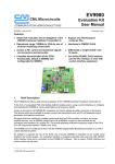
Flow Sensor Operation (Optional)
A
The flow sensor automatically detects drops falling in the drip chamber. The flow sensor will cause the pump to alarm
if a significant deviation from the infusion rate occurs. The flow sensor will also be able to detect empty containers. For
this reason we recommend use of a flow sensor wherever possible.
IVAC® Flow Sensor Model 192
Flanges
Handles
Pull back handles
Drip
chamber
1. Plug the flow sensor into the flow sensor interface located on the top rear part of the pump.
2. Attach the IVAC® Flow Sensor Model 192 to the drip chamber of the infusion set, by pulling back the handles. Refer to the illustration
above.
3. Proceed with load, priming, and set-up instructions as described in section “Getting Started”.
NOTE: Ensure drip chamber is half full and upright.
A
Always attach the flow sensor before you start an infusion .
Avoid using the flow sensor in direct sunlight.
Always ensure lens is clean.
1000DF00161 Issue 1
14/24
Specifications
Electrical Protection
Class I, Type CF
Electrical/Mechanical Safety
Complies with IEC/EN60601-1 and IEC/EN60601-2-24.
BATTERY SPECIFICATIONS Rechargeable Sealed Lead Acid. Automatically charges when the
pump is connected to AC power.
Battery Life - 6 hours @ 125ml/h
Battery Charging - 24 hours.
Electro Magnetic Compatibility (EMC)
Complies with IEC/EN60601-1-2 and IEC/EN60601-2-24.
Electrical Safety
IEC/EN60601-1;
Earth Leakage Current (Normal Condition) Maximum 100μA rms
(ungrounded) at 220V rms
Classification - Continuous mode of operation, Portable Equipment
AC Power Supply -
Alarm Conditions Alarm conditions cause the pump to display specific alarm messages, sound
an audible alarm, and except for the low battery and KVO mode alerts, cease
operation. Alarm and display messages include: FLO, door, hold, bat., batt.,
OCCL, RELOAD, Air and Err.
(See the ALARMS AND DISPLAY MESSAGES section of this DFU for message
descriptions.)
220 to 240V AC; 50/60 Hz; 0.07A; 3-wire grounded system.
Fuse Type -
Memory Retention -
2 X T63 mA 250V
At 25°C, the electronic memory of the pump will be retained for at
least 6 months when not powered up
Dimensions 133mm (w) x 193mm (h) x 184mm (d). Weight: approx. 2.7kg
(excluding power cable).
Protection against fluid ingress -
Air Sensor - Integral Ultrasonic Sensor.
Maximum time for activation of occlusion alarm:
IPX1 - Protected against vertically falling drops of water.
Time to alarm at 1ml/h is nominally 35 minutes
Time to alarm at 100ml/h is nominally 0.31 minutes
Environmental Specifications
Air in Line Accuracy:
Condition
Operating
Transport & Storage
100 μl ±50 μl
Temperature
+10°C to +40°C
-40°C to +70°C
Maximum Occlusion Alarm Pressure:
Humidity
30% to 75%
non-condensing
0% to 100%
11 psi (569 mmHg); Nominal: 6 to 8 psi
Atmospheric
Pressure
700hPa - 1060 hPa
500hPa - 1060hPa
Post Occlusion Bolus:
System Accuracy:
±5% with a 1.96 standard deviation under specified conditions.
Note: Accuracy specified under the following conditions:
Head height: 30"/76.2cm,
Test solution: distilled water,
Environmental: ambient temperature,
Back pressure: 20 gauge needle,
Infusion Set: Model 59073 (59073 has been superseded by G59073,
which is identical to the previous infusion set)
Bolus volume generated at 1 ml/h when the occlusion alarm threshold
is reached 0.5 ml
Bolus volume generated at 100 ml/h when the occlusion alarm
threshold is reached <0.5 ml
Critical Volume
25 ml at 999 ml/h is maximum incremental volume which can occur
in case of single point failure
Starting the Infusion / Set-up
Infusion Parameter
Range
Infusion Rate
1 - 999ml/h in steps of 1ml/h
VTBI
(0 - OFF), 1 - 9999ml in 1ml increments
VI (Total)
0 - 9999ml
KVO rate
5 ml/h or current set rate if less than 5
ml/h in primary operation
1000DF00161 Issue 1
15/24
Maintenance
Routine Maintenance Procedures
To ensure that this pump remains in good operating condition, it is important to keep it clean and carry out the routine maintenance procedures
described below. All servicing should only be performed by a qualified service engineer with reference to the Technical Service Manual (TSM).
Circuit diagrams and components parts lists and all other servicing information which will assist the qualified service engineer in performing repair of
the parts designated as repairable are available upon request from Cardinal Health.
A
If the pump is dropped, damaged, subjected to excessive moisture or high temperature, immediately take it out of service for
examination by a qualified service engineer.
All preventative and corrective maintenance and all such activities shall be performed at a compliant work place in
accordance with the information supplied. Cardinal Health, Alaris® Products will not be responsible should any of these actions be
performed outside the instructions or information supplied by Cardinal Health.
Refer to the Technical Service Manual for the access code for technical service.
INTERVAL
ROUTINE MAINTENANCE PROCEDURE
As per Hospital policy.
Thoroughly clean external surfaces of the pump before and after prolonged period of storage.
At least once per year
1.
(Refer to TSM for identification of 2.
parts)
3.
4.
A
Inspect AC power supply plug and cable for damage.
Perform functional tests as outlined in the Technical Service Manual.
Operate the pump on battery power until the battery low alarm then charge the battery to
confirm battery operation and charging.
Inspect mechanism for damage or excessive wear. Clean and lubricate the mechanism as outlined
in the Technical Service Manual.
Please refer to Technical Service Manual for calibration procedures. The units of measurement used in the calibration
procedure are standard SI (The International System of Units) units.
Replacing the Mains Fuses
If the pump continually illuminates the battery symbol and the AC power indicator light does not illuminate when the pump is connected to the AC
power supply and switched ON, either the power supply fuse in the AC plug, if fitted, or the internal fuses may have blown.
First check the power supply fuse in the AC mains plug, if fitted. If the AC power indicator light does not illuminate remove the pump from service. It
is recommended that the AC power fuses are only replaced by a qualified service engineer.
The fuses in the pump should only be replaced by a qualified service engineer. For further information regarding the replacement of fuses refer to
the Technical Service Manual.
A
If the fuses continue to blow, an electrical fault may have occurred and the pump and power supply should be checked
out by a qualified service engineer.
Battery Operation
The internal rechargeable battery allows continued operation when the AC power is unavailable, for example during patient transfer or AC
power failure. A fully charged battery will provide a minimum of 6 hours of operation at 125ml/h infusion rate. When connected to the AC
power supply for 24 hours, (whether the pump is in use or not) a battery pack will be fully charged.
The battery is maintenance free, sealed Lead Acid and requires no routine servicing. However, to achieve optimum operation, ensure that
the battery is fully recharged after full discharge, before storage, and at regular 3 month intervals during storage.
Charge retention will eventually degrade. Where retention is critical the internal battery should be replaced every 3 years.
It is recommended that only a qualified service engineer replaces the battery. For further information regarding the replacement of
batteries refer to the Technical Service Manual.
Test Routines
The test routines are designed to allow confirmation of many of the pump functions, defaults and calibrations without requiring internal
inspection. They do not represent a full calibration check.
A
See the Technical Service Manual for a complete list of the test procedures, access codes and calibration procedures.
1000DF00161 Issue 1
16/24
Cleaning and Storage
Cleaning the pump: Before the transfer of the pump to a new patient and periodically during the use, clean the pump by wiping over with a lint-free cloth lightly
dampened with warm water and a standard disinfectant / detergent solution.
A
Before cleaning always switch off and disconnect
from the AC power supply. Do not allow liquid to enter
the casing and avoid excess fluid build up on the pump.
Do not use aggressive cleaning agents as these may
damage the exterior surface of the pump.
Do not steam autoclave, ethylene oxide sterilise or
immerse this pump in any fluid.
Recommended cleaners are:
Brand
Concentration
Hibiscrub
20% (v/v)
Virkon
1% (w/v)
Do not use the following disinfectant types:
- NaDcc (such as PRESEPT)
- Hypochlorites (such as CHLORASOL)
- Aldehydes (such as CIDEX)
- Cationic Surfactants (such as Benzalkonium Chloride)
- Iodine (such as Betadine)
- Concentrated Isopropyl alcohol based cleaners will
degrade plastic parts.
Storing the pump: If the pump is to be stored for an extended period it should be first cleaned and the internal battery fully charged. Store in a clean, dry atmosphere at
room temperature and, if available, employ the original packaging for protection.
Once every 3 months during storage, carry out functional tests as described in the technical service manual and ensure that the internal battery is
fully charged.
Cleaning and storing the infusion set: The infusion set is a disposable single use item and should be discarded after use according to hospital protocol.
Cleaning the Flow Sensor: Before the transfer of the flow sensor to a new infusion set and periodically during use, clean the flow sensor by wiping over with a lint-free cloth lightly
dampened with warm water and a standard disinfectant / detergent solution. Ensure the connector does not get wet. Dry flow sensor before use.
To aid cleaning of flow sensors which have been heavily soiled, contaminated or if the handle operation is not free moving, then the flow sensor may
A
). The inside of the spring mechanism can be cleaned by activating it whilst submerged in the
be immersed and soaked in clean soapy water (see
water.
After cleaning, the sensor should be allowed to dry fully prior to use.
A
The plug of the flow sensor must not be immersed in water as damage will occur.
Disposal
Information on Disposal for Users of Waste Electrical & Electronic Equipment
U
This
symbol on the product and/or accompanying documents means that used electrical and electronic products should not be mixed with
household waste.
If you wish to discard electrical and electronic equipment, please contact your Cardinal Health affiliate office or distributor for further
information.
Disposing of this product correctly will help to save valuable resources and prevent any potential negative effects on human health and the
environment which could otherwise arise from inappropriate waste handling.
Information on Disposal in Countries outside the European Union
This symbol is only valid in the European Union. The product should be disposed of taking environmental factors into consideration. To ensure no
risk or hazard, remove the internal rechargeable battery and the Nickel Metal Hydride battery from the control board and dispose of as outlined by
the local country regulations. All other components can be safely disposed of as per local regulations.
1000DF00161 Issue 1
17/24
Infusion Sets
The IVAC® 598 Volumetric Pump uses standard, single-use, disposable infusion sets. The user is responsible for verifying the suitability of a
product used, if it is not recommended by Cardinal Health.
Standard infusion sets
G59033E
• 2 SmartSite® Needle-Free Valve Ports
• 15 Micron Filter & 0.2 Micron In Line Filter
• Length: 265cm
G59123E
• 2 SmartSite® Needle-Free Valve Ports
• 15 Micron Filter & 1.2 Micron In Line Filter
• Length: 260cm
G59021
• No Filter
• Length: 267cm
G59027E
• 3 SmartSite® Needle-Free Valve Ports
• No Filter
• Length: 260cm
G59073
• No Filter
• Length: 260cm
G59093
• 15 Micron Filter
• Length: 260cm
G59173E
• 1 SmartSite® Needle-Free Valve Port
• No Filter
• Length: 260cm
G59273E
• 2 SmartSite® Needle-Free Valve Ports
• No Filter
• Length: 260cm
G59293E
• 2 SmartSite® Needle-Free Valve Ports
• No Filter
• Length: 260cm
G59593
• 15 Micron Filter
• Length: 270cm
G59693E
• 1 SmartSite® Needle-Free Valve Port
• 15 Micron Filter
• Length: 255cm
G59793E
• 2 SmartSite® Needle-Free Valve Ports
• 15 Micron Filter
• Length: 255cm
G59903
• 15 Micron Filter
• Length: 250cm
G59394
• 15 Micron Filter
• Length: 270cm
G59016
• 15 Micron Filter
• Length: 275cm
G59953
• 15 Micron Filter
• Low Sorbing Infusion Set
• Length: 260cm
G59643
• 15 Micron Filter
• Opaque white PVC Infusion Set
• Length: 250cm
G59103E
• 2 SmartSite® Needle-Free Valve Ports
• 1 Burette (150ml)
• Length: 270cm
Blood Transfusion sets
G59024
• 200 Micron Filter
• Length: 295cm
G59393E
• 2 SmartSite® Needle-Free Valve Ports
• 200 Micron Filter
• Length: 270cm
G59980
• 200 Micron Filter
• Length: 250cm
G59895
• 200 Micron Filter
• Length: 255cm
A
G59893E
• 1 SmartSite® Needle-Free Valve Port
• 200 Micron Filter
• Length: 255cm
G59894
• 200 Micron Filter
• Length: 255cm
It is recommended that infusion sets are changed according to the instructions in the 'Changing the Infusion Set' section.
Carefully read the Directions For Use supplied with the infusion set prior to use.
Please note these drawings are not to scale
1000DF00161 Issue 1
18/24
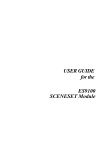
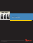
Trumpet and Flow Rate Curves
In this pump, as with all infusion systems, the action of the pumping mechanism and variations cause short-term fluctuations in rate
accuracy.
The following curves show typical performance of the system in two ways: 1) the accuracy of fluid delivery over various time periods is
measured (trumpet curves), and 2) the delay in onset of fluid flow when infusion commences (start-up curves).
Trumpet curves are named for their characteristic shape. They display discrete data averaged over particular time periods or 'observation
windows', not continuous data versus operating time. Over long observation windows, short term fluctuations have little effect on accuracy
as represented by the flat part of the curve. As the observation window is reduced, short term fluctuations have greater effects as represented
by the "mouth" of the trumpet.
Knowledge of system accuracy over various observation windows may be of interest when certain drugs are being administered. Short term
fluctuations in rate accuracy may have clinical impact depending on the half-life of the drug being infused and the degree of inter vascular
integration, the clinical effect cannot be determined from the trumpet curves alone.
The start-up curves represent continuous flow versus operating time for two hours from the start of the infusion. They exhibit the delay
in onset of delivery due to mechanical compliance and provide a visual representation of uniformity. Trumpet curves are derived from the
second hour of this data. Tests performed per IEC/EN60601-2-24 standard.
Start-up Graph at 1.0ml/h (24 hour)
2
1.8
1.8
1.6
1.6
1.4
1.4
1.2
1.2
Flow Rate (ml/h)
Flow Rate (ml/h)
Start-up Graph at 1.0ml/h (Initial Period)
2
1
0.8
0.6
1
0.8
0.6
0.4
0.4
0.2
0.2
0
0
0
20
40
60
80
100
0
120
20
40
60
20
G
G
A
A
G
A
D
A
D
G
A
D
Flow Rate Error (%)
Flow Rate Error (%)
G
-10
G
G
10
G
0
A
-10
D
D
A
G
A
D
A
D
G
A
D
D
D
-20
-20
-30
2
6
10
14
18
22
26
-30
30
2
6
Observation Window (Minutes)
D Minimum Rate Error G Maximum Rate Error A Overall Mean Error
10
14
18
22
26
30
Observation Window (Minutes)
D Minimum Rate Error G Maximum Rate Error A Overall Mean Error
Start-up Graph at 100ml/h (24 hour)
Start-up Graph at 100ml/h (Initial Period)
110
110
100
100
90
90
80
80
70
70
60
60
Flow Rate (ml/h)
Flow Rate (ml/h)
120
30
10
0
100
Trumpet Graph at 1.0ml/h (24 Hour)
Trumpet Graph at 1.0ml/h (Initial Period)
30
20
80
Time (minutes)
Time (minutes)
50
40
30
50
40
30
20
20
10
10
0
0
0
20
40
60
80
100
0
120
20
40
60
Time (minutes)
Time (minutes)
1000DF00161 Issue 1
19/24
80
100
120
Trumpet & Flow Rate Curves continued
Trumpet Graph at 100ml/h (24 Hour)
16
12
12
8
8
4
G
0
A
D
G
A
D
G
A
D
G
A
D
G
A
D
-4
Flow Rate Error (%)
Flow Rate Error (%)
Trumpet Graph at 100ml/h (Initial Period)
16
4
0
-12
-12
6
10
14
18
22
26
G
A
D
2
6
10
14
18
22
26
30
Observation Window (Minutes)
D Minimum Rate Error G Maximum Rate Error A Overall Mean Error
D Minimum Rate Error G Maximum Rate Error A Overall Mean Error
Start-up Graph at 999ml/h (24 hour)
Start-up Graph at 999ml/h (Initial Period)
1
1
0.8
0.8
0.6
0.6
Flow Rate (ml/h)
Flow Rate (ml/h)
G
A
D
-16
30
Observation Window (Minutes)
0.4
0.4
0.2
0.2
0
0
0
20
40
60
80
100
0
120
20
40
8
8
6
6
4
2
-2
D
A
G
D
A
G
D
A
G
D
A
G
Flow Rate Error (%)
10
D
A
G
0
-2
-4
-6
-8
-8
-10
10
14
120
2
-6
6
100
4
-4
2
80
Trumpet Graph at 999ml/h (24 Hour)
Trumpet Graph at 999ml/h (Initial Period)
10
0
60
Time (minutes)
Time (minutes)
Flow Rate Error (%)
G
A
D
-4
-8
2
G
A
D
D
-8
-16
G
A
18
22
26
G
A
D
G
A
D
G
A
D
G
A
D
G
A
D
-10
30
2
Observation Window (Minutes)
6
10
14
18
22
26
30
Observation Window (Minutes)
D Minimum Rate Error G Maximum Rate Error A Overall Mean Error
D Minimum Rate Error G Maximum Rate Error A Overall Mean Error
Note: The typical flow rate and trumpet curves are achieved using a recommended infusion set
1000DF00161 Issue 1
20/24
Products and Spare Parts
Alaris® Infusion System
Range of products in the Alaris® Infusion System product family are:
Part Number
Description
80013UN01
Alaris® GS Syringe Pump
80023UN01
Alaris® GH Syringe Pump
80033UND1
Alaris® CC Syringe Pump
80043UN01
Alaris® TIVA Syringe Pump
80053UN01
Alaris® PK Syringe Pump
80063UN01
Alaris® GP Volumetric Pump
80033UND1-G
Alaris® CC Syringe Pump with Guardrails® Safety Software
80023UN01-G
Alaris® GH Syringe Pump with Guardrails® Safety Software
80083UN00-xx*
Alaris® DS Docking Station
80203UNS0x-xx*
Alaris® Gateway Workstation
* For Docking Station and Workstation contact local customer services representative to obtain configurations availability and part numbers.
Spare Parts
A comprehensive list of spare parts for this pump is included within the Technical Service Manual.
The Technical Service Manual (1000SM00016) is available in electronic format on the World Wide Web at :www.cardinal.com/uk/alaris.
A username and password are required to access our manuals. Please contact a local customer services representative to obtain login
details.
Part Number
Description
303910
FUSE,1.5A,250V,NORM-BLO
129471
BATT PACK,80/90 SER
1001FAOPT91
AC Power Lead - UK
1001FAOPT92
AC Power Lead - European
1000DF00161 Issue 1
21/24
Service Contacts
For service contact your local Affiliate Office or Distributor:
AE
DE
IT
US
Cardinal Health,
PO Box 5527,
Dubai, United Arab Emirates.
Tel: (971) 4 28 22 842
Fax: (971) 4 28 22 914
Cardinal Health,
Pascalstr. 2,
52499 Baesweiler,
Deutschland.
Tel: (49) 2401 604 0
Fax: (49) 2401 604 121
Cardinal Health,
Via Ticino 4,
50019 Sesto Fiorentino,
Firenze, Italia.
Tél: (39) 055 30 33 93 00
Fax: (39) 055 34 00 24
Cardinal Health
10221 Wateridge Circle,
San Diego, CA 92121,
USA.
Tel: (1) 800 854 7128
Fax: (1) 858 458 6179
AU
ES
NL
ZA
Cardinal Health,
8/167 Prospect Highway,
Seven Hills, NSW 2147,
Australia.
Tel: (61) 2 9838 0255
Fax: (61) 2 9674 4444
Fax: (61) 2 9624 9030
Cardinal Health,
Avenida Valdeparra 27,
28108 - Alcobendas, Madrid,
España.
Tel: (34) 91 657 20 31
Fax: (34) 91 657 20 42
Cardinal Health,
Kantorenpand “Hoefse Wing”,
Printerweg, 11,
3821 AP Amersfoort,
Nederland.
Tel: (31) 33 455 51 00
Fax: (31) 33 455 51 01
Cardinal Health,
Unit 2 Oude Molen Business Park,
Oude Molen Road, Ndabeni,
Cape Town 7405, South Africa.
Tel: (27) (0) 860 597 572
Tel: (27) 21 510 7562
Fax: (27) 21 5107567
BE
FR
NO
Cardinal Health,
Otto De Mentockplein 19,
1853 Strombeek - Bever,
Belgium.
Tel: (32) 2 267 38 99
Fax: (32) 2 267 99 21
Cardinal Health,
Immeuble Antares - Technoparc,
2, rue Charles-Edouard Jeanneret.
78300 POISSY,
France.
Tél: (33) 1 30 06 74 60
Fax: (33) 1 39 11 48 34
Cardinal Health
Solbråveien 10 A,
1383 ASKER,
Norge.
Tel: (47) 66 98 76 00
Fax: (47) 66 98 76 01
CA
GB
NZ
Cardinal Health,
235 Shields Court,
Markham,
Ontario L3R 8V2,
Canada.
Tel: (1) 905-752-3333
Fax: (1) 905-752-3343
Cardinal Health,
The Crescent, Jays Close,
Basingstoke,
Hampshire, RG22 4BS,
United Kingdom.
Tel: (44) 0800 917 8776
Fax: (44) 1256 330860
Cardinal Health,
14b George Bourke Drive
Mt Wellington, Auckland
PO Box 14234
Panmure, Auckland
Tel: 09 270 2420
Freephone: 0508 422734
Fax: 09 270 6285
CN
HU
SE
Cardinal Health,
Shanghai Representative Office,
Suite 9B,
Century Ba-Shi Building,
398 Huai Hai Rd(M.),
Shanghai 200020,
China.
Tel: (56) 8621-63844603
Tel: (56) 8621-63844493
Fax: (56) 8621-6384-4025
Cardinal Health,
Döbrentei tér 1,
H-1013 Budapest,
Magyarország.
Tel: (36) 14 88 0232
Tel: (36) 14 88 0233
Fax: (36) 12 01 5987
Cardinal Health,
Hammarbacken 4B,
191 46 Sollentuna,
Sverige.
Tel: (46) 8 544 43 200
Fax: (46) 8 544 43 225
1000DF00161 Issue 1
22/24
Warranty
Cardinal Health, Alaris® Products ("Cardinal Health") warrants that:
(A) Each new infusion instrument (pump, controller or peripheral instrument) is free from defects in material and workmanship under
normal use and service for a period of two (2) years from the date of delivery by Cardinal Health to the original purchaser.
(B) Each new accessory is free from defects in material and workmanship under normal use and service for a period of ninety (90) days from
the date of delivery by Cardinal Health to the original purchaser.
(C) Each Mains Cable, Battery, Flow Sensor (ECD) and non-disposable probe is free from defects in material and workmanship under normal
use and service for a period of ninety (90) days from the date of delivery by Cardinal Health to the original purchaser.
(D) Each new Thermometer is free from defects in material and workmanship under normal use and service for a period of one (1) year from
the date of delivery by Cardinal Health to the original purchaser.
If any product requires repair during the applicable warranty period, the purchaser should communicate directly with its local Cardinal
Health service centre to determine the appropriate service facility. Except as provided otherwise in this warranty, repair or replacement will
be carried out at Cardinal Health's expense. The product requiring service should be returned promptly, properly packaged, and postage
prepaid by purchaser. Loss or damage in return shipment to Cardinal Health shall be at purchaser’s risk.
In no event shall Cardinal Health be liable for any incidental, indirect or consequential damages in connection with the purchase or use
of any Cardinal Health product. This warranty shall apply solely to the original purchaser. This warranty shall not apply to any subsequent
owner or holder of the product.
Furthermore, this warranty shall not apply to, and Cardinal Health shall not be responsible for, any loss or damage arising in connection with
the purchase or use of any Cardinal Health product which has been:
(A) repaired by anyone other than an authorised Cardinal Health service representative;
(B) altered in any way so as to affect, in Cardinal Health's judgement the stability or reliability of the product or has had the product’s serial
or lot number altered, effaced or removed;
(C) subjected to misuse or negligence or accident; or
(D) improperly maintained or used in any manner other than in accordance with the written instructions furnished by Cardinal Health.
This warranty is in lieu of all other warranties, express or implied, and of all other obligations or liabilities of Cardinal Health, and Cardinal
Health neither assumes nor authorises any representative or other person to assume for it any other liability in connection with the sale of
Cardinal Health products.
CARDINAL HEALTH DISCLAIMS ALL OTHER WARRANTIES, EXPRESS OR IMPLIED, INCLUDING ANY WARRANTY OF MERCHANTABILITY OR
FITNESS FOR A PARTICULAR PURPOSE.
Document History
Revision
CO Number
Date
1
7330
August 2007
1000DF00161 Issue 1
23/24
Index
A
K
Air-in-line
Accumulated air 12
single bubble 12
Air vent 6
KVO 11
L
Latex Content 7
Loading an Infusion Set 9
B
O
Operating Precautions 6, 7
Battery 15
Battery Operation 16
Blood infusion sets. See Infusion sets: Blood
P
Pressure 15
Prime 10, 11
C
R
Changing the Fluid Container 11
Changing the Infusion Set 11
Cleaning and Storage 17
Collapsable bags 6
Contents 1
Controls and Indicators 4
Replacing the Mains Fuses 16
Routine Maintenance Procedures 16
S
Semi Rigid containers 6
Service Contacts 22
Set change interval 11
SmartSite® Needle-Free System Instructions 11
Specifications 15
Standard infusion sets. See Infusion sets: Standard
Starting the Infusion 10
D
Disposal 17
Document History 23
E
Earth Conductor 7
Electromagnetic Compatibility 7
T
F
Test 16
Test Routines 16
Trumpet & Flow Rate Curves 19, 20
Features 3
Flow Rate Curves. See Trumpet & Flow Rate Curves
G
W
Getting Started 1, 8, 10, 11
Warranty 23
H
Hazards 7
I
Infusion sets
Blood 18
Standard 18
Introduction 2
1000DF00161 Issue 1
24/24
Alaris®, SmartSite® and IVAC® are registered trademarks
of Cardinal Health, Inc. or one of its subsidiaries.
All other trademarks belong to their respective owners.
© 2007 Cardinal Health, Inc. or one of its subsidiaries. All
rights reserved.
1000DF00161 Issue 1
This document contains proprietary information of
Cardinal Health, Inc. or one of its subsidiaries, and its
receipt or possession does not convey any rights to
reproduce its contents, or to manufacture or sell any
product described. Reproduction, disclosure, or use
other than for the intended purpose without specific
written authorization of Cardinal Health, Inc. or one of its
subsidiaries is strictly forbidden.
t
Cardinal Health
1180 Rolle
Switzerland
www.cardinal.com/uk/alaris