1
SAFETY PRECAUTIONS
(Please read these instructions before using this equipment.)
Before using this product, please read this manual and the relevant manuals introduced in this manual
carefully and pay full attention to safety to handle the product correctly. The precautions given in this
manual are concerned with this product only.
Refer to the user's manual of the CPU module to use for a description of the PLC system safety
precautions.
In this manual, the safety instructions are ranked as "DANGER" and "CAUTION".
DANGER
Indicates that incorrect handling may cause hazardous
conditions, resulting in death or severe injury.
CAUTION
Indicates that incorrect handling may cause hazardous
conditions, resulting in medium or slight personal injury or
physical damage.
CAUTION may also be linked to serious
Depending on circumstances, procedures indicated by
results.
In any case, it is important to follow the directions for usage.
Please save this manual to make it accessible when required and always forward it to the end user.
A-1
For Safe Operations
1. Prevention of electric shocks
DANGER
Never open the front case or terminal covers while the power is ON or the unit is running, as this
may lead to electric shocks.
Never run the unit with the front case or terminal cover removed. The high voltage terminal and
charged sections will be exposed and may lead to electric shocks.
Never open the front case or terminal cover at times other than wiring work or periodic
inspections even if the power is OFF. The insides of the module and servo amplifier are charged
and may lead to electric shocks.
Completely turn off the externally supplied power used in the system before mounting or removing
the module, performing wiring work, or inspections. Failing to do so may lead to electric shocks.
When performing wiring work or inspections, turn the power OFF, wait at least ten minutes, and
then check the voltage with a tester, etc. Failing to do so may lead to electric shocks.
Be sure to ground the module, servo amplifier and servomotor (Ground resistance: 100
or
less). Do not ground commonly with other devices.
The wiring work and inspections must be done by a qualified technician.
Wire the units after installing the module, servo amplifier and servomotor. Failing to do so may
lead to electric shocks or damage.
Never operate the switches with wet hands, as this may lead to electric shocks.
Do not damage, apply excessive stress, place heavy things on or sandwich the cables, as this
may lead to electric shocks.
Do not touch the module, servo amplifier, servomotor connector or terminal blocks while the
power is ON, as this may lead to electric shocks.
Do not touch the built-in power supply, built-in grounding or signal wires of the module and servo
amplifier, as this may lead to electric shocks.
2. For fire prevention
CAUTION
Install the module, servo amplifier, servomotor and regenerative resistor on incombustible.
Installing them directly or close to combustibles will lead to fire.
If a fault occurs in the module or servo amplifier, shut the power OFF at the servo amplifier's
power source. If a large current continues to flow, fire may occur.
When using a regenerative resistor, shut the power OFF with an error signal. The regenerative
resistor may abnormally overheat due to a fault in the regenerative transistor, etc., and may lead
to fire.
Always take heat measures such as flame proofing for the inside of the control panel where the
servo amplifier or regenerative resistor is installed and for the wires used. Failing to do so may
lead to fire.
Do not damage, apply excessive stress, place heavy things on or sandwich the cables, as this
may lead to fire.
A-2
3. For injury prevention
CAUTION
Do not apply a voltage other than that specified in the instruction manual on any terminal.
Doing so may lead to destruction or damage.
Do not mistake the terminal connections, as this may lead to destruction or damage.
Do not mistake the polarity (+/-), as this may lead to destruction or damage.
Do not touch the heat radiating fins of module or servo amplifier, regenerative resistor and
servomotor, etc., while the power is ON and for a short time after the power is turned OFF. In this
timing, these parts become very hot and may lead to burns.
Always turn the power OFF before touching the servomotor shaft or coupled machines, as these
parts may lead to injuries.
Do not go near the machine during test operations or during operations such as teaching.
Doing so may lead to injuries.
4. Various precautions
Strictly observe the following precautions. Mistaken handling of the unit may lead to faults,
injuries or electric shocks.
(1) System structure
CAUTION
Always install a leakage breaker on the module and servo amplifier power source.
If installation of an electromagnetic contactor for power shut off during an error, etc., is specified in
the instruction manual for the servo amplifier, etc., always install the electromagnetic contactor.
Install the emergency stop circuit externally so that the operation can be stopped immediately and
the power shut off.
Use the module, servo amplifier, servomotor and regenerative resistor with the correct
combinations listed in the instruction manual. Other combinations may lead to fire or faults.
Use the CPU module, base unit, and Simple Motion module with the correct combinations listed
in the instruction manual. Other combinations may lead to faults.
If safety standards (ex., robot safety rules, etc.,) apply to the system using the module, servo
amplifier and servomotor, make sure that the safety standards are satisfied.
Construct a safety circuit externally of the module or servo amplifier if the abnormal operation of
the module or servo amplifier differ from the safety directive operation in the system.
In systems where coasting of the servomotor will be a problem during the forced stop, emergency
stop, servo OFF or power supply OFF, use dynamic brakes.
Make sure that the system considers the coasting amount even when using dynamic brakes.
In systems where perpendicular shaft dropping may be a problem during the forced stop,
emergency stop, servo OFF or power supply OFF, use both dynamic brakes and electromagnetic
brakes.
The dynamic brakes must be used only on errors that cause the forced stop, emergency stop, or
servo OFF. These brakes must not be used for normal braking.
The brakes (electromagnetic brakes) assembled into the servomotor are for holding applications,
and must not be used for normal braking.
A-3
CAUTION
The system must have a mechanical allowance so that the machine itself can stop even if the
stroke limits switch is passed through at the max. speed.
Use wires and cables that have a wire diameter, heat resistance and bending resistance
compatible with the system.
Use wires and cables within the length of the range described in the instruction manual.
The ratings and characteristics of the parts (other than module, servo amplifier and servomotor)
used in a system must be compatible with the module, servo amplifier and servomotor.
Install a cover on the shaft so that the rotary parts of the servomotor are not touched during
operation.
There may be some cases where holding by the electromagnetic brakes is not possible due to the
life or mechanical structure (when the ball screw and servomotor are connected with a timing belt,
etc.). Install a stopping device to ensure safety on the machine side.
(2) Parameter settings and programming
DANGER
Set the parameter values to those that are compatible with the module, servo amplifier,
servomotor and regenerative resistor model and the system application. The protective functions
may not function if the settings are incorrect.
The regenerative resistor model and capacity parameters must be set to values that conform to
the operation mode and servo amplifier. The protective functions may not function if the settings
are incorrect.
Set the mechanical brake output and dynamic brake output validity parameters to values that are
compatible with the system application. The protective functions may not function if the settings
are incorrect.
Set the stroke limit input validity parameter to a value that is compatible with the system
application. The protective functions may not function if the setting is incorrect.
Set the servomotor encoder type (increment, absolute position type, etc.) parameter to a value
that is compatible with the system application. The protective functions may not function if the
setting is incorrect.
Use the program commands for the program with the conditions specified in the instruction
manual.
Set the sequence function program capacity setting, device capacity, latch validity range, I/O
assignment setting, and validity of continuous operation during error detection to values that are
compatible with the system application. The protective functions may not function if the settings
are incorrect.
A-4
DANGER
The input devices and data registers assigned to the link will hold the data previous to when
communication is terminated by an error, etc. Thus, an error correspondence interlock program
specified in the instruction manual must be used.
Use the interlock program specified in the intelligent function module's instruction manual for the
program corresponding to the intelligent function module.
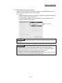
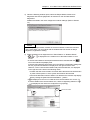
When connecting GX Works2 with the CPU module or connecting a personal computer with an
intelligent function module to modify data of a running programmable controller, configure an
interlock circuit in the program to ensure that the entire system will always operate safely.
For other forms of control (such as program modification or operating status change) of a running
programmable controller, read the relevant manuals carefully and ensure that the operation is
safe before proceeding. Especially, when a remote programmable controller is controlled by an
external device, immediate action cannot be taken if a problem occurs in the programmable
controller due to a communication failure. To prevent this, configure an interlock circuit in the
program, and determine corrective actions to be taken between the external device and CPU
module in case of a communication failure.
For the operating status of each station after a communication failure, refer to Section 8.1.7 in
this manual. Incorrect output or malfunction due to a communication failure may result in an
accident.
Do not write any data to the "system area" of the buffer memory in the intelligent function
module. Also, do not use any "use prohibited" signals as an output signal from the CPU module
to the intelligent function module.
Doing so may cause malfunction of the programmable controller system.
To set a refresh device in the network parameter, select the device Y for the remote output (RY)
refresh device. If a device other than Y, such as M and L, is selected, the CPU module holds the
device status even after its status is changed to STOP.
If a communication cable is disconnected, the network may be unstable, resulting in a
communication failure of multiple stations. Configure an interlock circuit in the program to ensure
that the entire system will always operate safely even if communications fail.
Failure to do so may result in an accident due to an incorrect output or malfunction.
(3) Transportation and installation
DANGER
Shut off the external power supply (all phases) used in the system before mounting or removing a
module. Failure to do so may result in electric shock or cause the module to fail or malfunction.
A-5
CAUTION
Transport the product with the correct method according to the mass.
Use the servomotor suspension bolts only for the transportation of the servomotor. Do not
transport the servomotor with machine installed on it.
Do not stack products past the limit.
When transporting the module or servo amplifier, never hold the connected wires or cables.
When transporting the servomotor, never hold the cables, shaft or detector.
When transporting the module or servo amplifier, never hold the front case as it may fall off.
When transporting, installing or removing the module or servo amplifier, never hold the edges.
Install the unit according to the instruction manual in a place where the mass can be withstood.
Do not get on or place heavy objects on the product.
Always observe the installation direction.
Keep the designated clearance between the module or servo amplifier and control panel inner
surface or the module and servo amplifier, module or servo amplifier and other devices.
Do not install or operate modules, servo amplifiers or servomotors that are damaged or that have
missing parts.
Do not block the intake/outtake ports of the servo amplifier and servomotor with cooling fan.
Do not allow conductive matter such as screw or cutting chips or combustible matter such as oil
enter the module, servo amplifier or servomotor.
The module, servo amplifier and servomotor are precision machines, so do not drop or apply
strong impacts on them.
Securely fix the module, servo amplifier and servomotor to the machine according to the
instruction manual. If the fixing is insufficient, these may come off during operation.
Always install the servomotor with reduction gears in the designated direction. Failing to do so
may lead to oil leaks.
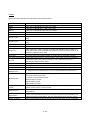
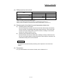
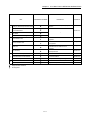
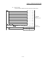
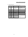
Store and use the unit in the following environmental conditions.
Environment
Ambient
temperature
Ambient humidity
Storage
temperature
Atmosphere
Altitude
Vibration
Conditions
Module/Servo amplifier
According to each instruction manual.
According to each instruction manual.
According to each instruction manual.
Servomotor
0°C to +40°C (With no freezing)
(32°F to +104°F)
80% RH or less
(With no dew condensation)
-20°C to +65°C
(-4°F to +149°F)
Indoors (where not subject to direct sunlight).
No corrosive gases, flammable gases, oil mist or dust must exist
1000m (3280.84ft.) or less above sea level
According to each instruction manual
When coupling with the servomotor shaft end, do not apply impact such as by hitting with a
hammer. Doing so may lead to detector damage.
Do not apply a load larger than the tolerable load onto the servomotor shaft. Doing so may lead
to shaft breakage.
A-6
CAUTION
When not using the module for a long time, disconnect the power line from the module or servo
amplifier.
Place the module and servo amplifier in static electricity preventing vinyl bags and store.
When storing for a long time, please contact with our sales representative.
Also, execute a trial operation.
Make sure that the connectors for the servo amplifier and peripheral devices have been securely
installed until a click is heard.
Not doing so could lead to a poor connection, resulting in erroneous input and output.
Use the programmable controller in an environment that meets the general specifications in the
user's manual for the CPU module used. Failure to do so may result in electric shock, fire,
malfunction, or damage to or deterioration of the product.
To mount the module, while pressing the module mounting lever located in the lower part of the
module, fully insert the module fixing projection(s) into the hole(s) in the base unit and press the
module until it snaps into place. Incorrect mounting may cause malfunction, failure or drop of the
module.
When using the programmable controller in an environment of frequent vibrations, fix the module
with a screw.
Tighten the screws within the specified torque range. Undertightening can cause drop of the
screw, short circuit or malfunction. Overtightening can damage the screw and/or module,
resulting in drop, short circuit, or malfunction.
Do not directly touch any conductive parts and electronic components of the module. Doing so
can cause malfunction or failure of the module.
When fumigants that contain halogen materials such as fluorine, chlorine, bromine, and iodine
are used for disinfecting and protecting wooden packaging from insects, they cause malfunction
when entering our products.
Please take necessary precautions to ensure that remaining materials from fumigant do not enter
our products, or treat packaging with methods other than fumigation (heat method). Additionally,
disinfect and protect wood from insects before packing products.
The module and the servo amplifier must not be used with parts which contain halogen-series
flame retardant materials (such as bromine) under coexisting conditions.
(4) Wiring
DANGER
Shut off the external power supply (all phases) used in the system before wiring.
Failure to do so may result in electric shock or cause the module to fail or malfunction.
A-7
CAUTION
Correctly and securely wire the wires. Reconfirm the connections for mistakes and the terminal
screws for tightness after wiring. Failing to do so may lead to run away of the servomotor.
After wiring, install the protective covers such as the terminal covers to the original positions.
Do not install a phase advancing capacitor, surge absorber or radio noise filter (option FR-BIF)
on the output side of the servo amplifier.
Correctly connect the output side (terminal U, V, W). Incorrect connections will lead the
servomotor to operate abnormally.
Do not connect a commercial power supply to the servomotor, as this may lead to trouble.
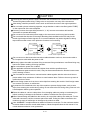
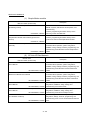
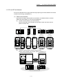
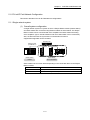
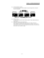
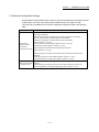
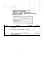
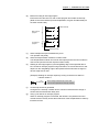
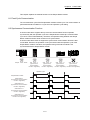
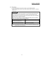
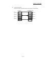
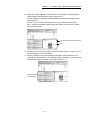
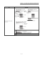
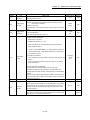
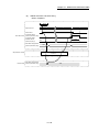
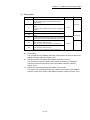
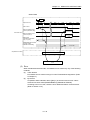
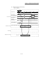
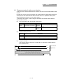
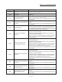
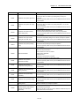
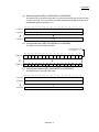
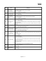
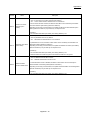
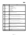
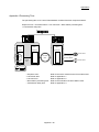
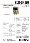
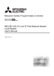
Do not mistake the direction of the surge absorbing diode installed on the DC relay for the
control signal output of brake signals, etc. Incorrect installation may lead to signals not being
output when trouble occurs or the protective functions not functioning.
Servo amplifier
DOCOM
Control output
signal
Servo amplifier
24VDC
DOCOM
Control output
signal
RA
DICOM
24VDC
RA
DICOM
For the sink output interface
For the source output interface
Do not connect or disconnect the connection cables between each unit, the encoder cable or
PLC expansion cable while the power is ON.
Securely tighten the cable connector fixing screws and fixing mechanisms. Insufficient fixing may
lead to the cables combing off during operation.
Do not bundle the power line or cables.
Use applicable solderless terminals and tighten them with the specified torque.
If any solderless spade terminal is used, it may be disconnected when the terminal screw comes
loose, resulting in failure.
Do not install the control lines or communication cables together with the main circuit lines or
power cables. Keep a distance of 100mm or more between them. Failure to do so may result in
malfunction due to noise.
Prevent foreign matter such as dust or wire chips from entering the module. Such foreign matter
can cause a fire, failure, or malfunction.
A protective film is attached to the top of the module to prevent foreign matter, such as wire
chips, from entering the module during wiring. Do not remove the film during wiring. Remove it for
heat dissipation before system operation.
Place the cables in a duct or clamp them. If not, dangling cable may swing or inadvertently be
pulled, resulting in damage to the module or cables or malfunction due to poor contact.
When disconnecting the cable from the module, do not pull the cable by the cable part. For the
cable with connector, hold the connector part of the cable. Pulling the cable connected to the
module may result in malfunction or damage to the module or cable.
Use 1000BASE-T-compliant Ethernet cables for Ethernet connection. For the maximum stationto-station distance and the overall cable distance, follow the specifications in this manual. If not,
normal data transmission is not guaranteed.
A-8
(5) Trial operation and adjustment
CAUTION
Confirm and adjust the program and each parameter before operation. Unpredictable
movements may occur depending on the machine.
Extreme adjustments and changes may lead to unstable operation, so never make them.
When using the absolute position system function, on starting up, and when the module or
absolute value motor has been replaced, always perform a home position return.
Before starting test operation, set the parameter speed limit value to the slowest value, and
make sure that operation can be stopped immediately by the forced stop, etc. if a hazardous
state occurs.
Before starting the operation, confirm the brake function.
(6) Usage methods
CAUTION
Immediately turn OFF the power if smoke, abnormal sounds or odors are emitted from the
module, servo amplifier or servomotor.
Always execute a test operation before starting actual operations after the program or
parameters have been changed or after maintenance and inspection.
Do not attempt to disassemble and repair the units excluding a qualified technician whom our
company recognized.
Do not make any modifications to the unit.
Keep the effect or electromagnetic obstacles to a minimum by installing a noise filter or by using
wire shields, etc.
Electromagnetic obstacles may affect the electronic devices used near the module or servo
amplifier.
When using the CE Mark-compliant equipment design, refer to the "EMC Installation Guidelines"
(data number IB(NA)-67339) and refer to the corresponding EMC guideline information for the
servo amplifiers and other equipment.
Note that when the reference axis speed is designated for interpolation operation, the speed of
the partner axis (2nd axis, 3rd axis and 4th axis) may be larger than the set speed (larger than
the speed limit value).
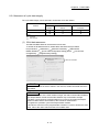
Use the units with the following conditions.
Item
Input power
Input frequency
Tolerable momentary
power failure
Conditions
According to each instruction manual.
According to each instruction manual.
According to each instruction manual.
A-9
(7) Corrective actions for errors
CAUTION
If an error occurs in the self diagnosis of the module or servo amplifier, confirm the check details
according to the instruction manual, and restore the operation.
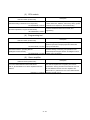
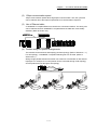
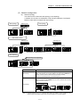
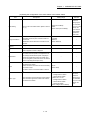
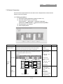
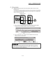
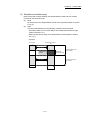
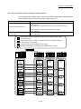
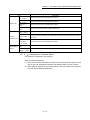
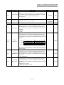
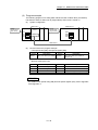
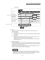
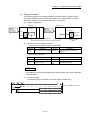
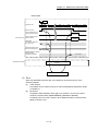
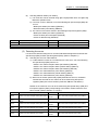
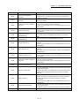
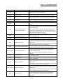
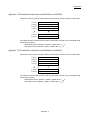
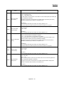
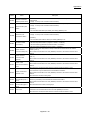
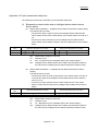
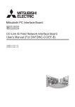
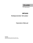
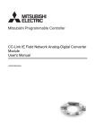
If a dangerous state is predicted in case of a power failure or product failure, use a servomotor
with electromagnetic brakes or install a brake mechanism externally.
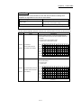
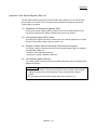
Use a double circuit construction so that the electromagnetic brake operation circuit can be
operated by emergency stop signals set externally.
Shut off with servo ON signal OFF,
alarm, electromagnetic brake signal.
Servo motor
RA1
Electromagnetic
B
brakes
Shut off with the
emergency stop
signal (EMG).
EMG
24VDC
If an error occurs, remove the cause, secure the safety and then resume operation after alarm
release.
The unit may suddenly resume operation after a power failure is restored, so do not go near the
machine. (Design the machine so that personal safety can be ensured even if the machine
restarts suddenly.)
(8) Maintenance, inspection and part replacement
DANGER
Do not touch any terminal while power is on. Doing so will cause electric shock or malfunction.
Shut off the external power supply (all phases) used in the system before cleaning the module or
retightening the module fixing screw. Failure to do so may result in electric shock.
A - 10
CAUTION
Before performing online operations (especially, program modification, forced output, and
operating status change) for the running CPU module on another station from GX Works2 over
CC-Link IE Field Network, read relevant manuals carefully and ensure the safety. Improper
operation may damage machines or cause accidents.
Do not disassemble or modify the modules. Doing so may cause failure, malfunction, injury, or
a fire.
Use any radio communication device such as a cellular phone or PHS (Personal Handy-phone
System) more than 25cm away in all directions from the programmable controller. Failure to do
so may cause malfunction.
Shut off the external power supply (all phases) used in the system before mounting or
removing a module. Failure to do so may cause the module to fail or malfunction.
Tighten the screw within the specified torque range. Undertightening can cause drop of the
screw, short circuit or malfunction. Overtightening can damage the screw and/or module,
resulting in drop, short circuit, or malfunction.
Perform the daily and periodic inspections according to the instruction manual.
Perform maintenance and inspection after backing up the program and parameters for the
module and servo amplifier.
Do not place fingers or hands in the clearance when opening or closing any opening.
Periodically replace consumable parts such as batteries according to the instruction manual.
Do not touch the lead sections such as ICs or the connector contacts.
Before touching the module, always touch grounded metal, etc. to discharge static electricity from
human body. Failure to do so may cause the module to fail or malfunction.
Do not directly touch the module's conductive parts and electronic components.
Touching them could cause an operation failure or give damage to the module.
Do not place the module or servo amplifier on metal that may cause a power leakage or wood,
plastic or vinyl that may cause static electricity buildup.
Do not perform a megger test (insulation resistance measurement) during inspection.
When replacing the module or servo amplifier, always set the new module settings correctly.
A - 11
CAUTION
When the module or absolute value motor has been replaced, carry out a home position return
operation using one of the following methods, otherwise position displacement could occur.
1) After writing the servo data to the Simple Motion module using programming software, switch
on the power again, then perform a home position return operation.
After maintenance and inspections are completed, confirm that the position detection of the
absolute position detector function is correct.
Do not drop or impact the battery installed to the module.
Doing so may damage the battery, causing battery liquid to leak in the battery. Do not use the
dropped or impacted battery, but dispose of it.
Do not short circuit, charge, overheat, incinerate or disassemble the batteries.
The electrolytic capacitor will generate gas during a fault, so do not place your face near the
module or servo amplifier.
The electrolytic capacitor and fan will deteriorate. Periodically replace these to prevent
secondary damage from faults. Please contact with our sales representative.
Lock the control panel and prevent access to those who are not certified to handle or install
electric equipment.
Do not mount/remove the module and base or terminal block more than 50 times (IEC61131-2compliant), after the first use of the product. Failure to do so may cause malfunction.
Do not burn or break a module and servo amplifier. Doing so may cause a toxic gas.
(9) About processing of waste
When you discard module, servo amplifier, a battery (primary battery) and other option articles,
please follow the law of each country (area).
CAUTION
This product is not designed or manufactured to be used in equipment or systems in situations
that can affect or endanger human life.
When considering this product for operation in special applications such as machinery or
systems used in passenger transportation, medical, aerospace, atomic power, electric power, or
submarine repeating applications, please contact your nearest Mitsubishi sales representative.
Although this product was manufactured under conditions of strict quality control, you are
strongly advised to install safety devices to forestall serious accidents when it is used in facilities
where a breakdown in the product is likely to cause a serious accident.
(10) General cautions
CAUTION
All drawings provided in the instruction manual show the state with the covers and safety
partitions removed to explain detailed sections. When operating the product, always return the
covers and partitions to the designated positions, and operate according to the instruction
manual.
A - 12
CONDITIONS OF USE FOR THE PRODUCT
(1) Mitsubishi programmable controller ("the PRODUCT") shall be used in conditions;
i) where any problem, fault or failure occurring in the PRODUCT, if any, shall not lead to any major or
serious accident; and
ii) where the backup and fail-safe function are systematically or automatically provided outside of the
PRODUCT for the case of any problem, fault or failure occurring in the PRODUCT.
(2) The PRODUCT has been designed and manufactured for the purpose of being used in general industries.
MITSUBISHI SHALL HAVE NO RESPONSIBILITY OR LIABILITY (INCLUDING, BUT NOT LIMITED TO
ANY AND ALL RESPONSIBILITY OR LIABILITY BASED ON CONTRACT, WARRANTY, TORT,
PRODUCT LIABILITY) FOR ANY INJURY OR DEATH TO PERSONS OR LOSS OR DAMAGE TO
PROPERTY CAUSED BY the PRODUCT THAT ARE OPERATED OR USED IN APPLICATION NOT
INTENDED OR EXCLUDED BY INSTRUCTIONS, PRECAUTIONS, OR WARNING CONTAINED IN
MITSUBISHI'S USER, INSTRUCTION AND/OR SAFETY MANUALS, TECHNICAL BULLETINS AND
GUIDELINES FOR the PRODUCT.
("Prohibited Application")
Prohibited Applications include, but not limited to, the use of the PRODUCT in;
• Nuclear Power Plants and any other power plants operated by Power companies, and/or any other cases
in which the public could be affected if any problem or fault occurs in the PRODUCT.
• Railway companies or Public service purposes, and/or any other cases in which establishment of a
special quality assurance system is required by the Purchaser or End User.
• Aircraft or Aerospace, Medical applications, Train equipment, transport equipment such as Elevator and
Escalator, Incineration and Fuel devices, Vehicles, Manned transportation, Equipment for Recreation and
Amusement, and Safety devices, handling of Nuclear or Hazardous Materials or Chemicals, Mining and
Drilling, and/or other applications where there is a significant risk of injury to the public or property.
Notwithstanding the above, restrictions Mitsubishi may in its sole discretion, authorize use of the
PRODUCT in one or more of the Prohibited Applications, provided that the usage of the PRODUCT is
limited only for the specific applications agreed to by Mitsubishi and provided further that no special quality
assurance or fail-safe, redundant or other safety features which exceed the general specifications of the
PRODUCTs are required. For details, please contact the Mitsubishi representative in your region.
A - 13
INTRODUCTION
Thank you for purchasing the Mitsubishi MELSEC-Q series programmable controllers.
This manual describes the overview of the CC-Link IE Field Network, and operating procedure, system
configuration, parameter setting, functions, programming, and troubleshooting of the QD77GF, CC-Link IE
Field Network Simple Motion module (hereafter abbreviated as master/local module).
Before using this product, please read this manual and the relevant manuals carefully and develop familiarity
with the functions and performance of the MELSEC-Q series programmable controller to handle the product
correctly.
When applying the program examples introduced in this manual to the actual system, ensure the applicability
and confirm that it will not cause system control problems.
Please make sure that the end users read this manual.
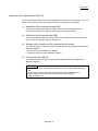
REMARK
• Unless otherwise specified, this manual describes the program examples in which
the I/O numbers of X/Y00 to X/Y1F are assigned for a Q series Simple Motion
module. I/O number assignment is required for using the program examples
described in the manual.
For I/O number assignment, refer to the following.
QnUCPU User's Manual (Function Explanation, Program Fundamentals)
• Operating procedures are explained using GX Works2.
A - 14
REVISIONS
The manual number is given on the bottom left of the back cover.
Print Date
Manual Number
Mar., 2013
Feb., 2014
IB(NA)-0300203-A
IB(NA)-0300203-B
Sep., 2014
IB(NA)-0300203-C
Revision
First edition
[Additional function]
CC IE Field configuration window,
Remote operation (RESET operation only)
[Additional correction/partial correction]
SAFETY PRECAUTIONS, RELEVANT MANUALS
[Additional correction/partial correction]
Appendix 4.5
Japanese Manual Version IB-0300201
This manual confers no industrial property rights or any rights of any other kind, nor does it confer any patent licenses.
Mitsubishi Electric Corporation cannot be held responsible for any problems involving industrial property rights which
may occur as a result of using the contents noted in this manual.
2013 MITSUBISHI ELECTRIC CORPORATION
A - 15
CONTENTS
SAFETY PRECAUTIONS ............................................................................................................................. A- 1
CONDITIONS OF USE FOR THE PRODUCT .............................................................................................A-13
INTRODUCTION ............................................................................................................................................A-14
REVISIONS ....................................................................................................................................................A-15
CONTENTS ....................................................................................................................................................A-16
COMPLIANCE WITH THE EMC AND LOW VOLTAGE DIRECTIVES .......................................................A-19
RELEVANT MANUALS .................................................................................................................................A-20
MANUAL PAGE ORGANIZATION ................................................................................................................A-22
TERMS ...........................................................................................................................................................A-23
PACKING LIST...............................................................................................................................................A-26
1. CC-LINK IE FIELD NETWORK
1- 1 to 1- 8
1.1 CC-Link IE Field Network ........................................................................................................................ 1- 2
1.2 Simple Motion Modules............................................................................................................................ 1- 4
2. NAMES OF EACH PART
2- 1 to 2- 4
2.1 Names of Each Part ................................................................................................................................. 2- 2
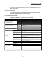
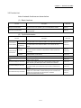
3. SPECIFICATIONS
3- 1 to 3- 8
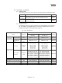
3.1 General Specifications ............................................................................................................................. 33.2 Performance Specifications ..................................................................................................................... 33.3 Function List ............................................................................................................................................. 33.4 Specifications of Input/Output Signals with CPU Module ....................................................................... 33.4.1 List of input/output signals with CPU module ................................................................................... 33.4.2 Details of input signals (QD77GF
CPU module)........................................................................ 33.5 Buffer Memory (Network Function) ......................................................................................................... 34. PROCEDURES BEFORE OPERATION
2
2
3
5
5
6
7
4- 1 to 4- 2
4.1 Procedures Before Operation .................................................................................................................. 4- 2
5. SYSTEM CONFIGURATION
5- 1 to 5- 8
5.1 CC-Link IE Field Network Configuration ................................................................................................. 55.1.1 Single network system ...................................................................................................................... 55.2 Network Components .............................................................................................................................. 55.2.1 Cables ................................................................................................................................................ 55.2.2 Hubs................................................................................................................................................... 55.3 Applicable Systems .................................................................................................................................. 5-
A - 16
2
2
7
7
7
8
6. INSTALLATION AND WIRING
6- 1 to 6- 2
6.1 Installation and Wiring .............................................................................................................................. 6- 2
7. PARAMETER SETTING
7- 1 to 7-30
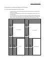
7.1 Parameter and Backup ............................................................................................................................ 7- 2
7.2 Parameter List .......................................................................................................................................... 7- 3
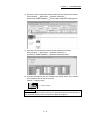
7.3 Network Settings ...................................................................................................................................... 7- 5
7.4 Network Configuration Settings ............................................................................................................... 7- 8
7.5 Network Operation Settings ..................................................................................................................... 7-20
7.6 Refresh Parameters ................................................................................................................................. 7-21
7.7 Interrupt Settings ...................................................................................................................................... 7-25
8. FUNCTIONS
8- 1 to 8-22
8.1 Fixed Cycle Communication .................................................................................................................... 8- 2
8.2 Synchronous Communication Function .................................................................................................. 8- 2
8.3 Cyclic Transmission ................................................................................................................................. 8- 4
8.3.1 Data flow and link device assignment .............................................................................................. 8- 4
8.3.2 Link refresh ........................................................................................................................................ 8- 6
8.3.3 Direct access to link devices ............................................................................................................. 8- 8
8.3.4 Assurance of cyclic data integrity ..................................................................................................... 8-12
8.3.5 Input and output status settings in case of failure ............................................................................ 8-16
8.3.6 Output status setting for CPU module STOP ................................................................................... 8-18
8.3.7 Cyclic transmission stop and restart ................................................................................................. 8-19
8.4 Transient Transmission............................................................................................................................ 8-20
8.4.1 Communications within the same network ....................................................................................... 8-20
8.5 Reserved Station Specification and Temporary Cancel of Reserved Station Setting ........................... 8-21
8.6 Interrupt Request to the CPU Module ..................................................................................................... 8-22
9. CC-LINK IE FIELD NETWORK DIAGNOSTICS
9- 1 to 9-26
9.1 Diagnostic Items ....................................................................................................................................... 9- 2
9.2 Starting Diagnostics ................................................................................................................................. 9- 4
9.3 Diagnostic Window................................................................................................................................... 9- 8
9.4 Link Start/Stop .......................................................................................................................................... 9-16
9.5 Network Event History ............................................................................................................................. 9-19
9.6 Reserved Station Function Enable .......................................................................................................... 9-22
9.7 Remote Operation .................................................................................................................................... 9-26
10. DEDICATED INSTRUCTIONS
10- 1 to 10-48
10.1 List of Dedicated Instructions .............................................................................................................. 10- 2
10.2 Precautions for Dedicated Instructions ............................................................................................... 10- 4
10.2.1 Precautions for dedicated instructions (common) ........................................................................ 10- 4
10.2.2 Precautions for link dedicated instructions ................................................................................... 10- 5
10.3 Understanding the Documentation on Dedicated Instructions ........................................................... 10- 6
10.4 JP/GP.READ (Reading Data from Another Station) ........................................................................... 10- 8
10.5 JP/GP.SREAD (Reading Data from Another Station) ........................................................................ 10-16
A - 17
10.6 JP/GP.WRITE (Writing Data to Another Station) ................................................................................ 10-22
10.7 JP/GP.SWRITE (Writing Data to Another Station) ............................................................................. 10-33
10.8 ZP.REMFR (Reading Data from the Intelligent Device Station/Remote Device Station) ................. 10-39
10.9 ZP.REMTO (Writing Data to the Intelligent Device Station/Remote Device Station) ........................ 10-44
11. PROGRAMMING
11- 1 to 11-24
11.1 Precautions for Programming .............................................................................................................. 11- 2
11.2 Example of Communications Between the Master Station and a Head Module ............................... 11- 3
11.2.1 System configuration example ..................................................................................................... 11- 3
11.2.2 Setting in the master station ......................................................................................................... 11- 5
11.2.3 Setting in the head module ........................................................................................................... 11- 7
11.2.4 Checking the network status......................................................................................................... 11-10
11.2.5 Program example .......................................................................................................................... 11-11
11.3 Using Link Special Relay (SB) and Link Special Register (SW) ........................................................ 11-15
12. TROUBLESHOOTING
12- 1 to 12-26
12.1 Before Troubleshooting ....................................................................................................................... 12- 2
12.2 Troubleshooting Procedure ................................................................................................................. 12- 2
12.3 Checking the LEDs .............................................................................................................................. 12- 7
12.4 Troubleshooting by Symptom .............................................................................................................. 12- 9
12.4.1 Cyclic transmission cannot be performed .................................................................................... 12- 9
12.4.2 Transient transmission cannot be performed............................................................................... 12-10
12.4.3 Station is disconnected from the network .................................................................................... 12-10
12.4.4 Station is repeatedly disconnected and reconnected .................................................................. 12-10
12.4.5 Communication is unstable ........................................................................................................... 12-10
12.5 Error Code List (D000H to DFFFH) ..................................................................................................... 12-11
12.6 Checking the Status by System Monitor ............................................................................................. 12-25
Appendices
Appendix- 1 to Appendix-34
Appendix 1 Details of Buffer Memory Addresses ........................................................................... Appendix- 2
Appendix 1.1 Link device area (Un\G59392 to Un\G63007) ...................................................... Appendix- 2
Appendix 1.2 RX offset/size information (Un\G63152 to Un\G63359) ....................................... Appendix- 4
Appendix 1.3 RY offset/size information (Un\G63360 to Un\G63567) ....................................... Appendix- 4
Appendix 1.4 RWw offset/size information (Un\G63568 to Un\G63775) ................................... Appendix- 5
Appendix 1.5 RWr offset/size information (Un\G63776 to Un\G63983) ..................................... Appendix- 5
Appendix 1.6 Station information (Un\G64016 to Un\G64041) .................................................. Appendix- 6
Appendix 2 Link Special Relay (SB) List ......................................................................................... Appendix- 8
Appendix 3 Link Special Register (SW) List.....................................................................................Appendix-16
Appendix 4 Processing Time ............................................................................................................Appendix-28
Appendix 4.1 Link refresh time .....................................................................................................Appendix-29
Appendix 4.2 Link scan time .........................................................................................................Appendix-29
Appendix 4.3 Cyclic transmission delay time ...............................................................................Appendix-30
Appendix 4.4 Transmission delay time of dedicated instructions ................................................Appendix-31
Appendix 4.5 Calculation formula for operation cycle ..................................................................Appendix-31
Appendix 5 Comparison of QJ71GF11-T2 .......................................................................................Appendix-32
A - 18
COMPLIANCE WITH THE EMC AND LOW VOLTAGE DIRECTIVES
(1) Method of ensuring compliance
To ensure that Mitsubishi programmable controllers maintain EMC and Low
Voltage Directives when incorporated into other machinery or equipment, certain
measures may be necessary. Please refer to one of the following manuals.
• QCPU User's Manual (Hardware Design, Maintenance and Inspection)
• Safety Guidelines
(This manual is included with the CPU module or base unit.)
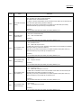
The CE mark on the side of the programmable controller indicates compliance
with EMC and Low Voltage Directives.
(2) For the product
To ensure that this product maintains EMC and Low Voltage Directives, please
refer to the "MELSEC-Q QD77GF Simple Motion Module User's Manual
(Positioning Control)".
A - 19
RELEVANT MANUALS
(1) Simple Motion module
Manual Name
Description
<Manual number (model code)>
MELSEC-Q QD77GF Simple Motion Module User's Manual
Specifications of the QD77GF and information on how to
(Positioning Control)
establish a system, maintenance and inspection, and
troubleshooting
Functions, programming and buffer memory for the
<IB-0300202, 1XB956> positioning control of the QD77GF
MELSEC-Q/L QD77MS/QD77GF/LD77MS/LD77MH
Simple Motion Module User's Manual (Synchronous
Functions, programming and buffer memory for the
Control)
synchronous control of the Simple Motion module
<IB-0300174, 1XB943>
MELSEC-Q QD77GF Simple Motion Module User's Manual
Overview of CC-Link IE Field Network, and specifications,
(Network)
procedures before operation, system configuration,
installation, wiring, settings, functions, programming, and
troubleshooting of the MELSEC-Q series Simple Motion
<IB-0300203, 1XB957> module
(2) CC-Link IE Field Network
Manual name
Description
<manual number (model code)>
MELSEC-Q CC-Link IE Field Network Master/Local Module
Overview of CC-Link IE Field Network, and specifications,
User's Manual
procedures before operation, system configuration,
installation, wiring, settings, functions, programming, and
troubleshooting of the MELSEC-Q series master/local
<SH-080917ENG, 13JZ47> module.
MELSEC-QS CC-Link IE Field Network
Overview of CC-Link IE Field Network, and specifications,
Master/Local Module User's Manual
procedures before operation, system configuration,
installation, wiring, settings, functions, programming, and
troubleshooting of the MELSEC-QS series master/local
<SH-080969ENG, 13JZ53> module
MELSEC-L CC-Link IE Field Network Head Module
Specifications, procedures before operation, system
User's Manual
configuration, installation, wiring, settings, and
<SH-080919ENG, 13JZ48> troubleshooting of the head module
CC-Link IE Field Network Ethernet Adapter Module
Specifications, procedures before operation, system
User's Manual
configuration, installation, wiring, settings, and
<SH-080939ENG, 13JZ50> troubleshooting of the Ethernet adapter module
CC-Link IE Field Network Interface Board User's Manual
Specifications, procedures before operation, system
(For SW1DNC-CCIEF-B)
configuration, settings, functions, programming, and
troubleshooting of the CC-Link IE Field Network interface
<SH-080980ENG, 13JZ58> board
A - 20
(3) CPU module
Manual name
Description
<manual number (model code)>
QCPU User's Manual
Specifications of the hardware (CPU modules, power supply
(Hardware Design, Maintenance and Inspection)
modules, base units, batteries, and memory cards), system
<SH-080483ENG, 13JR73> maintenance and inspection, and troubleshooting
QnUCPU User's Manual
Functions and devices of the CPU module, and
(Function Explanation, Program Fundamentals)
<SH-080807ENG, 13JZ27>
programming
(4) Programming tool
Manual name
Description
<manual number (model code)>
GX Works2 Version1 Operating Manual (Common)
System configuration, parameter settings, and online
operations (common to Simple project and Structured
<SH-080779ENG, 13JU63> project) of GX Works2
GX Works2 Version1 Operating Manual
Parameter settings, monitoring, and operations of the
(Intelligent Function Module)
predefined protocol support function of intelligent function
<SH-080921ENG, 13JU69> modules, using GX Works2
(5) Servo amplifier
Manual Name
Description
<Manual number (model code)>
CC-Link IE Field Network Interface with Motion
This manual explains the I/O signals, parts names,
MR-J4-_B-RJ010/MR-J3-T10 Servo Amplifier Instruction
parameters, start-up procedure and others for CC-Link
Manual
IE Field Network interface AC servo amplifier with
Motion MR-J4-_B-RJ010 and CC-Link IE Field Network
<SH-030117, 1CW810>
interface unit MR-J3-T10..
A - 21
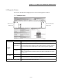
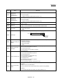
MANUAL PAGE ORGANIZATION
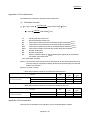
The symbols used in this manual are shown below.
The following symbols represent the buffer memories supported for each axis.
(A serial No. is inserted in the "*" mark.)
Symbol
[Md. * ]
Description
Symbol that indicates monitor data item.
Reference
-
Representation of numerical values used in this manual.
Error codes, X/Y devices and link devices are represented in hexadecimal.
Buffer memory addresses and setting data are represented in decimal or
hexadecimal. Data ended by "H" or "h" is represented in hexadecimal.
(Example) 10.........Decimal
10H......Hexadecimal
A - 22
TERMS
Unless otherwise specified, this manual uses the following terms.
Term
QCPU
Description
Another term for the MELSEC-Q series CPU module
LCPU
Another term for the MELSEC-L series CPU module
QSCPU
Another term for the MELSEC-QS series CPU module
QnACPU
Another term for the MELSEC-QnA series CPU module
ACPU
System A CPU
System B CPU
Another term for the MELSEC-A series CPU module
A CPU module where the system A connector of a tracking cable is connected in a redundant
system
A CPU module where the system B connector of a tracking cable is connected in a redundant
system
Control system CPU
A CPU module that controls operations in a redundant system
Standby system CPU
A CPU module that stands by in case the control system fails in a redundant system
A CPU module that controls connected I/O modules and intelligent function modules. In a
Control CPU
multiple CPU system, there are multiple CPU modules and each connected module can be
controlled by a different CPU module.
GX Works2
The product name of the software package for the MELSEC programmable controllers
CC-Link IE Field Network A high-speed and large-capacity open field network that is based on Ethernet (1000BASE-T)
CC-Link
A field network system where data processing for control and information can be
simultaneously performed at high speed.
Simple Motion module
The abbreviation for the QD77GF16 CC-Link IE Field Network Simple Motion module
Head module
The abbreviation for the LJ72GF15-T2 CC-Link IE Field Network head module
Ethernet adapter module
The abbreviation for the NZ2GF-ETB CC-Link IE Field Network Ethernet adapter module
CC-Link IE Field Network
interface board
The abbreviation for the Q81BD-J71GF11-T2 CC-Link IE Field Network interface board
A generic term for the following modules:
• CC-Link IE Field Network module
Network module
• CC-Link IE Controller Network module
• Ethernet interface module
• MELSECNET/H module
• MELSECNET/10 module
Intelligent function
A MELSEC-Q/L series module that has functions other than input and output, such as an A/D
module
converter module and D/A converter module
Ethernet device
Master station
Remote I/O station
A generic term for devices, such as personal computers, that support IP (Internet Protocol)
communications
A station that controls the entire network. This station can perform cyclic transmission and
transient transmission with all stations. Only one master station can be used in a network.
A station that exchanges I/O signals (bit data) with the master station by cyclic transmission
A - 23
Term
Description
A station that exchanges I/O signals (bit data) and I/O data (word data) with another station by
Remote device station
cyclic transmission. This station responds to a transient transmission request from another
station.
A station that exchanges I/O signals (bit data) and I/O data (word data) with another station by
Intelligent device station
cyclic transmission. This station responds to a transient transmission request from another
station and also issues a transient transmission request to another station.
Servo amplifier (drive
unit)
Abbreviation for CC-Link IE Field Network compatible servo amplifier (drive unit).
Slave station
A generic term for remote I/O station, remote device station, and intelligent device station
Synchronous
A generic term for a servo amplifier and a slave station set to synchronous communication
communication device
mode.
Asynchronous
communication device
Reserved station
Cyclic transmission
Transient transmission
A generic term for a slave station set to other than synchronous communication mode.
A station reserved for future use. This station is not actually connected, but counted as a
connected station.
A function by which data are periodically exchanged among stations on the same network
using link devices (RX, RY, RWw, and RWr)
A function of communication with another station, which is used when requested by a
dedicated instruction or GX Works2
Data link
Generic term for cyclic transmission and transient transmission
Seamless
Communication that allows users to access a different kind of networks without having to
communications
consider the differences as if data were exchanged within one single network
Dedicated instruction
An instruction that simplifies programming for using functions of intelligent function modules
A dedicated instruction used for transient transmission with another station.
Link dedicated instruction
This instruction allows a master/local module to communicate with programmable controllers
on the same network (CC-Link IE Field Network) and on other networks (Ethernet, CC-Link IE
Controller Network, and MELSECNET/H).
CC-Link dedicated
instruction
A dedicated instruction used for transient transmission with a CC-Link IE Field Network device.
This instruction allows a master/local module to communicate with the device on the same
network.
Return
Process of restarting data link when a station recovers from an error
Disconnection
A process of stopping data link if a data link error occurs
Device
A device (X, Y, M, D, or others) in a CPU module
A - 24
Term
Link device
Remote input (RX)
Remote output (RY)
Remote register (RWr)
Remote register (RWw)
Link special relay (SB)
Link special register (SW)
Description
A device (RX, RY, RWr, or RWw) in a module on CC-Link IE Field Network
Bit data input from a slave station to the master station.
Refer to Section 8.3.1.
Bit data output from the master station to a slave station.
Refer to Section 8.3.1.
Word data input from a slave station to the master station.
Refer to Section 8.3.1.
Word data output from the master station to a slave station.
Refer to Section 8.3.1.
Bit data that indicates the operating status and data link status of a module on CC-Link IE Field
Network
Word data that indicates the operating status and data link status of a module on CC-Link IE
Field Network
Link scan (Link scan
Time required for all the stations on the network to transmit data. The link scan time depends
time)
on data volume and the number of transient transmission requests.
Data transfer between a link device in a module on CC-Link IE Field Network and a device in a
Link refresh
CPU module. Link refresh is performed in the END processing of the CPU module's sequence
Baton pass
A token to send data over a network
scan.
Buffer memory
Buffer memory address
RAS
A memory in an intelligent function module, where data (such as setting values and monitoring
values) exchanged with a CPU module are stored
An address that indicates the storage location of data assigned to the buffer memory in an
intelligent function module
The abbreviation for Reliability, Availability, and Serviceability. This term refers to usability of
automated equipment.
READ
The abbreviation for JP.READ and GP.READ
SREAD
The abbreviation for JP.SREAD and GP.SREAD
WRITE
The abbreviation for JP.WRITE and GP.WRITE
SWRITE
The abbreviation for JP.SWRITE and GP.SWRITE
REMFR
The abbreviation for ZP.REMFR
REMTO
The abbreviation for ZP.REMTO
A - 25
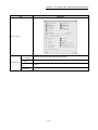
PACKING LIST
The following items are included in the package of this product. Before use, check that all the items are
included.
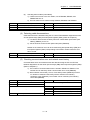
(1) QD77GF16
QD77GF16
Before Using the Product
A - 26
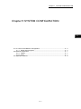
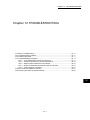
Chapter 1 CC-LINK IE FIELD NETWORK
1
Chapter 1 CC-LINK IE FIELD NETWORK
1.1 CC-Link IE Field Network .............................................................................................. 1- 2
1.2 Simple Motion Modules ................................................................................................. 1- 4
1-1
Chapter 1 CC-LINK IE FIELD NETWORK
1.1 CC-Link IE Field Network
CC-Link IE Field Network is a high-speed and large-capacity open field network that is based
on Ethernet technology (1000BASE-T).
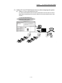
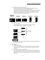
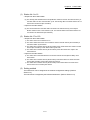
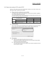
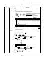
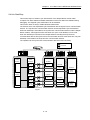
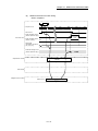
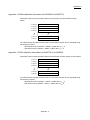
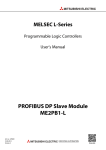
(1) Data communication
High-speed and large-capacity data communication is available between a master
station and slave stations on CC-Link IE Field Network.
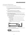
(a) Periodic communication (cyclic transmission)
Data is periodically communicated among stations within the same network.
(Refer to Section 8.3.)
Master station
(QD77GF)
Servo
amplifier
Servo
amplifier
Intelligent
device station
Intelligent
device station
Servo
amplifier
Servo
amplifier
Intelligent
device station
Intelligent
device station
CPU module
Master
station
X
RX
RX
RX
Y
RY
RY
RY
RWw
RWw
RWw
RWr
RWr
RWr
W
Internal
memory
(b)
Internal
memory
Internal
memory
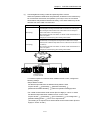
Irregular communications (transient transmission)
Data is communicated upon request. (Refer to Section 8.4.)
CPU module
Command
Master station
Intelligent
device station
Instruction
Write
request
Device
1234H
Device
1234H
1-2
Chapter 1 CC-LINK IE FIELD NETWORK
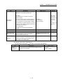
(2) 1Gbps communication speed
1Gbps communication speed allows high-speed communication. Also, the cycle time
can be reduced due to the improved performance of communication response.
(3) Use of Ethernet cable
A 1000BASE-T-compliant Ethernet is used for the connection interface. The wiring cost
can be reduced because 1000BASE-T-compliant Ethernet cables are commercially
available. (Refer to Section 5.2.)
1000BASE-T
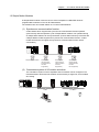
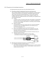
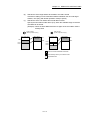
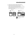
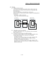
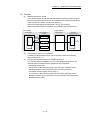
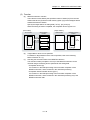
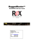
(4) Flexible wiring for system arrangements
The network can be wired into star topology and line topology. (Refer to Section 5.1.1.)
For star topology, a 1000BASE-T compliant switching hub can be used. (Refer to
Section 5.2.2.)
Wiring is highly flexible because a network can consist of a combination of star and line
topologies. For example, the control panels can be connected through a star topology
and the production lines through a line topology.
Star topology
Line topology
Line topology
1-3
Line topology
Chapter 1 CC-LINK IE FIELD NETWORK
1.2 Simple Motion Modules
A Simple Motion module is used to connect a servo amplifier or a MELSEC-Q series
programmable controller to CC-Link IE Field Network.
The module works as a master station on CC-Link IE Field Network.
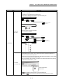
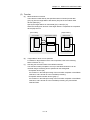
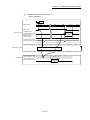
(1) Synchronous communication function
A slave station which supports the synchronous communication function operates
synchronously with the operation cycle of Simple Motion module. The operation timing
of multiple slave stations can be synchronized. (A slave station which synchronizes with
a Simple Motion module supports the synchronous communication function. A slave
module which does not support the synchronous communication function is also
connectable.)
Simple Motion module
Slave station
(Synchronous
communication
function:
Supported)
Slave station
(Synchronous
communication
function:
Supported)
Slave station
(Synchronous
communication
function:
Not supported)
(2) Coexistence system of I/O module and driver
The coexistence system of servo amplifiers and I/O modules can be configured. The
network between drivers and I/O modules can be wired by a single line, and it enables
wire saving.
Simple Motion module
Drivers
I/O modules
1-4
Chapter 1 CC-LINK IE FIELD NETWORK
(3) Multiple axes system configuration
The servo amplifiers can be controlled up to 16 axes. By connecting slave stations
excluding servo amplifiers the system can be configured up to 120 axes.
(4) High-speed periodic communication (cyclic transmission)
Since transmission delay time is short, delay caused during communication does not
need to be considered (if the link scan time of each Simple Motion module is shorter
than the scan time of the CPU module).
Command
High speed
POINT
Simple Motion modules can perform cyclic transmissions in combination with the
following functions:
(Refer to Section 3.3.)
• Auto transfer of data between the link devices in the Simple Motion module and
the devices in the CPU module
• Direct access to the link devices in the Simple Motion module by a program
• Cyclic data assurance in units of 32 bits or per station
• Status setting (hold or clear) of input data from a slave station where a cyclic error
has occurred
• Station reservation for future connection, and others
1-5
Chapter 1 CC-LINK IE FIELD NETWORK
(5) Irregular communications with another station (transient transmission)
(a)
Reading or writing data
A Simple Motion module can access other stations by dedicated instructions.
(Refer to Section 10.1.)
CPU module
Master station
Command
Intelligent
device station
READ
Device
Device
1234H
1234H
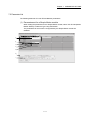
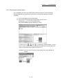
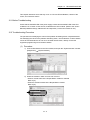
(6) Settings and diagnostics by GX Works2
(a)
Setting parameters
Parameters for Simple Motion modules can be set using GX Works2. Creating
parameter setting programs is not necessary. (Refer to Chapter 7.)
1-6
Chapter 1 CC-LINK IE FIELD NETWORK
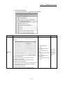
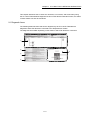
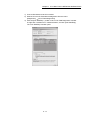
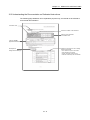
(b)
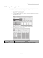
Checking CC-Link IE Field Network status graphically
The CC-Link IE Field Network status can be checked using GX Works2. Error
locations, error causes, and event history are displayed on the window. This
allows the system to quickly recover from errors.
(Refer to Chapter 9.)
1-7
Chapter 1 CC-LINK IE FIELD NETWORK
(7) Adding CC-Link IE Field Network devices without stopping the system
(a)
Adding CC-Link IE Field Network devices
CC-Link IE Field Network devices whose parameters have not been set can be
added without powering off the system. (Refer to the user's Manual of the head
module.)
Connection of an added module can be
recognized, and setting a station No. on the
window allows tentative operation.
Addition
1-8
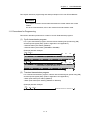
Chapter 2 NAMES OF EACH PART
Chapter 2 NAMES OF EACH PART
2.1 Names of Each Part ....................................................................................................... 2- 2
2-1
2
Chapter 2 NAMES OF EACH PART
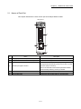
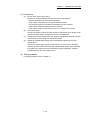
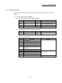
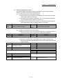
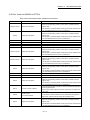
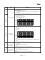
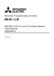
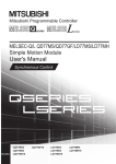
2.1 Names of Each Part
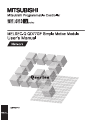
This chapter describes the names of each part of the Simple Motion module.
QD77GF16
1)
3)
4)
2)
5)
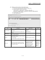
No.
Name
Description
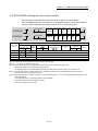
1)
LED (upper part on the front)
Refer to this section (1).
2)
LED (CC-Link IE Field connector section)
Refer to this section (2).
Connector to connect the mechanical system input, manual
pulse generator/incremental synchronous encoder, or forced
3)
External input signal connector
stop input. (26-pin connector)
Refer to the "MELSEC-Q QD77GF Simple Motion Module
User's Manual (Positioning Control)" for details.
4)
CC-Link IE Field Network cable connector
Connector to connect the servo amplifier.
5)
Serial number plate
Indicates the serial number written on the rating plate.
2-2
Chapter 2 NAMES OF EACH PART
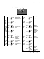
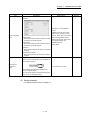
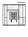
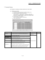
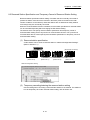
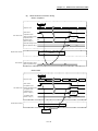
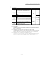
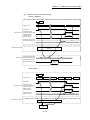
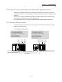
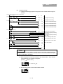
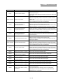
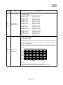
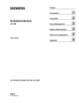
(1) LED (upper part on the front)
QD77GF16
RUN
AX
D LINK
RD
L ERR.
SD
ERR.
RUN
LED is
OFF.
RUN
LED is
ON.
ERR.
LED is
OFF.
ERR.
LED is
flashing.
AX LED
is OFF.
ERR.
LED is
flashing.
AX LED
is
flashing.
ERR.
LED is
ON.
LED Display
RUN
SD
ERR.
RUN
SD
ERR.
RUN
SD
ERR.
RUN
SD
ERR.
RUN
SD
ERR.
RUN
AX LED
is ON.
AX LED
is OFF.
SD
ERR.
RUN
SD
ERR.
Description
AX
D LINK
RD
L ERR.
Hardware failure,
watch dog timer error
SD LED
is ON.
AX
D LINK
RD
L ERR.
Operates normally.
SD LED
is OFF.
AX
D LINK
RD
L ERR.
Token pass not
executed for some
stations
D LINK
LED is
ON.
AX
D LINK
RD
L ERR.
Axis error
D LINK
LED is
flashing.
AX
D LINK
RD
L ERR.
System error,
CPU stop error,
error in all stations,
station number
duplication,
invalid network
parameter
D LINK
LED is
OFF.
Axis operation in
progress
RD LED
is ON.
An axis stops or is on
standby.
RD LED
is OFF.
AX
D LINK
RD
L ERR.
AX
D LINK
RD
L ERR.
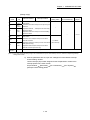
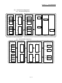
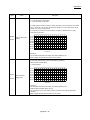
LED Display
RUN
AX
D LINK
SD
RD
ERR.
L ERR.
RUN
SD
ERR.
RUN
SD
ERR.
RUN
SD
ERR.
RUN
SD
ERR.
RUN
L ERR.
LED is
ON.
L ERR.
LED is
OFF.
SD
ERR.
RUN
SD
ERR.
RUN
SD
ERR.
RUN
SD
ERR.
Sending data.
AX
D LINK
RD
L ERR.
Data not sent
AX
D LINK
RD
L ERR.
Data link in
operation (cyclic
transmission in
progress)
AX
D LINK
RD
L ERR.
Data link in
operation (cyclic
transmission
stopped)
AX
D LINK
RD
L ERR.
Data link not
performed
(disconnected)
AX
D LINK
RD
L ERR.
AX
D LINK
RD
L ERR.
AX
D LINK
RD
L ERR.
AX
D LINK
RD
L ERR.
: ON,
2-3
Description
Receiving data.
Data not received
Frame error
detection
Frame error not
detected
: Flashing,
: OFF
Chapter 2 NAMES OF EACH PART
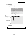
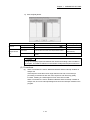
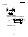
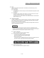
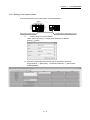
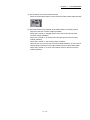
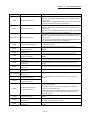
(2) CC-Link IE Field Network connector section
L ER
LINK
LED Display
L ER
L ER LED is
ON.
LINK
L ER
L ER LED is
OFF.
LINK
L ER
LINK LED is
ON.
LINK
L ER
LINK LED is
OFF.
LINK
Description
Receive data error
Receive data operates normally.
Linkup in progress.
Linkdown in progress.
:ON,
2-4
: OFF
Chapter 3 SPECIFICATIONS
Chapter 3 SPECIFICATIONS
3
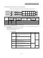
3.1 General Specifications .................................................................................................. 33.2 Performance Specifications .......................................................................................... 33.3 Function List ................................................................................................................... 33.4 Specifications of Input/Output Signals with CPU Module ........................................... 33.4.1 List of input/output signals with CPU module .................................................. 33.4.2 Details of input signals (QD77GF
CPU module) ...................................... 33.5 Buffer Memory (Network Function) .............................................................................. 3-
3-1
2
2
3
5
5
6
7
Chapter 3 SPECIFICATIONS
This chapter describes the specifications, function list, I/O signal, and buffer memory of the
Simple Motion module.
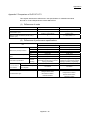
3.1 General Specifications
For the general specifications of the Simple Motion module, refer to "MELSEC-Q QD77GF
Simple Motion Module User's Manual (Positioning Control)".
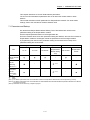
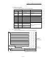
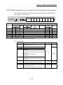
3.2 Performance Specifications
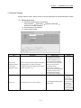
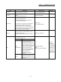
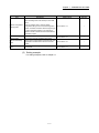
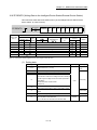
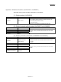
Performance specifications for the network function are shown below.
Item
Specifications
Operation cycle
0.88ms/1.77ms/3.55ms
Maximum link points per network
(excluding a servo amplifier)
Maximum link points per station
Maximum number of send points per station
Ethernet part
Number of connectable
stations per network
Connected stations type
Maximum number of networks
RWw
1024 points, 2KB
RWr
1024 points, 2KB
RX
8192 points, 1KB
RY
8192 points, 1KB
RWw
1024 points, 2KB
RWr
1024 points, 2KB
RX
8192 points, 1KB
RY
8192 points, 1KB
RWw
1024 points, 2KB
RY
8192 points, 1KB
Communication speed
1Gbps
Network topology
Line topology and star topology (Coexistence of line topology and star
topology is possible.)
Connection cable
An Ethernet cable that meets the 1000BASE-T standard: Category 5e or
higher (double shielded, STP), straight cable (Refer to Section 5.2.1.)
Maximum station-to-station
distance
100m max. (Compliant with ANSI/TIA/EIA-568-B (Category 5e))
(Refer to "MELSEC-Q QD77GF Simple Motion Module User's Manual
(Positioning Control)".)
Overall cable distance
Line topology: 12000m (when cables are connected to one master station
and 120 slave stations)
Star topology: Depends on the system configuration.
Number of cascade
connections
Up to 20 (follows hub performance)
Servo amplifier
16 modules
Slave station excluding a
servo amplifier
104 modules
Intelligent device station
Available
Remote device station
Available
Remote I/O station
Available
239
Communication method
Token passing method
Number of occupied I/O points
32 points (I/O assignment: Intelligent 32 points)
3-2
Chapter 3 SPECIFICATIONS
3.3 Function List
Lists of network functions are shown below.
(1) Basic functions
Function
Description
Reference
Fixed cycle communication
The slave device is communicated in the fixed cycle. The communication
cycle is the same as an operation cycle of the Simple Motion module.
Section 8.1
Synchronous communication
The processing cycles of the Simple Motion module and each slave station
are synchronized.
Section 8.2
(2) Cyclic transmission
Function
Communications
using RX and RY
Communications
Communications
with other stations
using RWr and
RWw
Access to devices
and link devices
Description
Reference
The master station communicates I/O data in units of bits with other stations.
The master station communicates I/O data in units of words with other
stations.
Section 7.4
Section 8.3.1
Link refresh
Transfer between the link device of the Simple Motion module and the device
Section 7.6
of the CPU module mounted with a Simple Motion module is performed
Section 8.3.2
automatically.
Direct access to
link devices
The program accesses the link devices (RX, RY, RWr, RWw, SB or SW) of
the Simple Motion module directly.
Section 8.3.3
The cyclic data integrity is assured in units of 32 bits or station-based units.
Section 8.3.4
Assurance of cyclic data integrity
Input status setting for data link faulty Whether input data from another station where a data link error occurs is
station
cleared or held is selected.
Section 8.3.5
Output status setting for CPU STOP
When the CPU module mounted with a Simple Motion module is set to
STOP, whether cyclic data output is held or cleared can be selected.
Output status setting for CPU stop
error
When a stop error occurs in the CPU module where a Simple Motion module
is mounted, whether cyclic transmission output is held or cleared can be
Section 8.3.5
selected.
Cyclic transmission stop and restart
During debugging and other operations, cyclic transmission is stopped. (Data
Section 8.3.7
reception from a slave station and data sending from the own station are
Section 9.4
stopped.) Also, the stopped cyclic transmission is restarted.
Transient transmission does not stop.
3-3
Section 8.3.6
Chapter 3 SPECIFICATIONS
(3) Transient transmission
Function
Communications within the same
network
Description
Transient transmission is performed to other stations using dedicated
instructions and GX Works2.
Reference
Chapter 10
(4) Diagnostic functions
Function
Description
Reference
The status of CC-Link IE Field Network can be checked using GX Works2.
CC-Link IE Field Network diagnostics The error locations, error causes, corrective actions, and event history can be Chapter 9
checked in GX Works2.
Module error collection function
The error information occurred in the Simple Motion module is notified and
accumulated. Then, the confirmation of error information and troubleshooting Section 12.2
can be executed using GX Works2.
(5) Other functions
Function
Description
Reserved station specification
The reserved stations are included in the number of stations that will be
connected to the network in the future without actually connecting them.
Reserved stations are not detected as faulty stations even though they are
not actually connected.
Temporary cancel of the reserved
station setting
Reserved station specification can be temporarily cancelled without changing
the parameters.
Interrupt request to a CPU module
Interrupt conditions are checked every link scan, and if the interrupt
conditions are met, an interrupt request is made to the CPU module to start
the interrupt program.
3-4
Reference
Section 8.5
Section 9.6
Section 7.7
Section 8.6
Chapter 3 SPECIFICATIONS
3.4 Specifications of Input/Output Signals with CPU Module
3.4.1 List of input/output signals with CPU module
The Simple Motion module uses 32 input points and 32 output points for exchanging data
with the CPU module.
The input/output signals when the head I/O number of Simple Motion module is set to "0H"
are shown below.
If it is set to other than "0H", change the I/O number according to setting of head I/O number.
Device X refers to the signals input from the Simple Motion module to the CPU module, and
device Y refers to the signals output from the CPU module to the Simple Motion module.
Signal direction: QD77GF16
Device No.
CPU module
Signal name
Signal direction: CPU module
Device No.
QD77GF16
Signal name
X0
READY
Y0
PLC READY
X1
Synchronization flag
Y1
All axis servo ON
X2
Y2
X3
Y3
X4
Y4
X5
Y5
X6
Y6
X7
Y7
Use prohibited
X8
Y8
X9
Y9
XA
YA
XB
YB
XC
YC
XD
YD
XE
YE
XF
Module READY
Use prohibited
YF
X10
Axis 1
Y10
Axis 1
X11
Axis 2
Y11
Axis 2
X12
Axis 3
Y12
Axis 3
X13
Axis 4
Y13
Axis 4
X14
Axis 5
Y14
Axis 5
X15
Axis 6
Y15
Axis 6
X16
Axis 7
Y16
Axis 7
X17
Axis 8
Y17
Axis 8
X18
Axis 9
Y18
Axis 9
BUSY
X19
Axis 10
Y19
Axis 10
X1A
Axis 11
Y1A
Axis 11
X1B
Axis 12
Y1B
Axis 12
X1C
Axis 13
Y1C
Axis 13
X1D
Axis 14
Y1D
Axis 14
X1E
Axis 15
Y1E
Axis 15
X1F
Axis 16
Y1F
Axis 16
3-5
Positioning start
Chapter 3 SPECIFICATIONS
Important
[Y2 to YF] and [X2 to XE] are used by the system, and cannot be used by the user.
If these devices are used, the operation of the QD77GF16 will not be guaranteed.
3.4.2 Details of input signals (QD77GF
CPU module)
The ON/OFF timing and conditions of the input signals are shown below.
Refer to the "MELSEC-Q QD77GF Simple Motion Module User's Manual (Positioning
Control)" for signals not listed in the table below.
Device No.
XF
Module READY
Signal name
OFF:
Module operation
disabled
ON:
Module operation
enabled
Details
• The signal to confirm the module operation ready status.
• After the power is turned from OFF to ON, this signal turns from
OFF to ON when the module is normal. If the module is in error,
this signal turns from ON to OFF.
[Normal]
ON
PLC READY signal
[Y0] OFF
READY signal
[X0] OFF
Module READY
[XF] OFF
ON
ON
Power supply ON
[Error]
ON
PLC READY signal
[Y0] OFF
READY signal
[X0] OFF
Module READY
[XF] OFF
ON
ON
Power supply ON
3-6
Chapter 3 SPECIFICATIONS
3.5 Buffer Memory (Network Function)
The buffer memory is used to exchange data between the Simple Motion module and the
CPU module.
Buffer memory values are defaulted when the CPU module is reset or the system is powered
off. Buffer memories for the network function are shown below.
Address
(Decimal
(Hexadecimal))
Name
Initial value
59392 to 59903
(E800H to E9FFH)
Remote input (RX)
59904 to 60415
(EA00H to EBFFH)
Remote output (RY)
60416 to 61439
(EC00H to EFFFH)
Remote register (RWw)
61440 to 62463
(F000H to F3FFH)
Read
0
Link special relay (SB)
• 62464 to 62465 for
read and write
• 62466 to 62495 for
read only
Link special register (SW)
• 62496 to 62527 for
read and write
• 62528 to 63007 for
read only
System area
Station No.17 RX offset
63153
(F6B1H)
Station No.17 RX size
RX offset/size information
to
63358
(F77EH)
Station No.120 RX offset
63359
(F77FH)
Station No.120 RX size
63360
(F780H)
Station No.17 RY offset
63361
(F781H)
Station No.17 RY size
RY offset/size information
Appendix 1.1
–
63152
(F6B0H)
to
Read
Remote register (RWr)
Link device area
62496 to 63007
(F420H to F61FH)
to
Refer to
Read, write
62464 to 62495
(F400H to F41FH)
63008 to 63151
(F620H to F6AFH)
Read, write
to
63566
(F84EH)
Station No.120 RY offset
63567
(F84FH)
Station No.120 RY size
3-7
0
Read
Appendix 1.2
0
Read
Appendix 1.3
Chapter 3 SPECIFICATIONS
Address
(Decimal
(Hexadecimal))
Name
63568
(F850H)
Station No.17 RWw offset
63569
(F851H)
Station No.17 RWw size
to
RWw offset/size information
to
63774
(F91EH)
Station No.120 RWw
offset
63775
(F91FH)
Station No.120 RWw size
63776
(F920H)
Station No.17 RWr offset
63777
(F921H)
Station No.17 RWr size
to
RWr offset/size information
to
63982
(F9EFH)
Station No.120 RWr offset
63983
(F9F0H)
Station No.120 RWr size
64016
(FA10H)
Station number
64017
(FA11H)
64018
(FA12H)
64019
(FA13H)
Model type
Station (network card) information
Model code
0
Read
Appendix 1.4
0
Read
Appendix 1.5
0
Read and write
Own station
information
Read
Appendix 1.6
System area
–
Controller information
valid/invalid flag
64026
(FA1AH)
Manufacturer code
64027
(FA1BH)
Model type
Station (controller) information
Model code
64029
(FA1DH)
Version
64030 to 64039
(FA1EH to FA27H)
Model name string
64040 to 64041
(FA28H to FA29H)
Vendor-specific device
information
64042 to 64047
(FA2AH to FA2FH)
Refer to
Version
64025
(FA19H)
64028
(FA1CH)
Read, write
Manufacturer code
64020
(FA14H)
64021 to 64024
(FA15H to FA18H)
Initial value
System area
Own station
information
Read
Appendix 1.6
–
3-8
Chapter 4 PROCEDURES BEFORE OPERATION
Chapter 4 PROCEDURES BEFORE
OPERATION
4
4.1 Procedures Before Operation ........................................................................................ 4- 2
4-1
Chapter 4 PROCEDURES BEFORE OPERATION
4.1 Procedures Before Operation
For the procedures before operation of the Simple Motion module, refer to "MELSEC-Q
QD77GF Simple Motion Module User's Manual (Positioning Control)".
4-2
Chapter 5 SYSTEM CONFIGURATION
Chapter 5 SYSTEM CONFIGURATION
5
5.1 CC-Link IE Field Network Configuration ...................................................................... 55.1.1 Single network system ..................................................................................... 55.2 Network Components ..................................................................................................... 55.2.1 Cables ............................................................................................................... 55.2.2 Hubs .................................................................................................................. 55.3 Applicable Systems ........................................................................................................ 5-
5-1
2
2
7
7
7
8
Chapter 5 SYSTEM CONFIGURATION
5.1 CC-Link IE Field Network Configuration
This section describes CC-Link IE Field Network configurations.
5.1.1 Single network system
(1) Overall system configuration
A single network system is a system in which a Simple Motion module (master station)
and slave stations are connected using Ethernet cables as shown below. The Simple
Motion module can be connected with servo amplifiers and slave stations excluding
servo amplifiers. (Up to 120 slave stations and one master station can be connected.)
Also, the devices which the synchronous communication function is
supported/unsupported can be coexisted.
Switching hub
Ethernet cable
(1000BASE-T)
Master station
Slave station
1 station
Up to 120 stations
Set the station No. as shown below depending on the connected device to the Simple
Motion module.
Station No.
Connected device
1 to 16
Servo amplifier
17 to 120
Slave station excluding a servo amplifier
5-2
Chapter 5 SYSTEM CONFIGURATION
(2) Network configuration
(a)
Star topology
Network topology
The network can be wired into star topology or line topology.
A network can consist of a combination of star and line topologies. The Simple
Motion module does not support the ring topology.
Switching hub
Line topology
Star and line mixed
Switching hub
Switching hub
Ring topology
Ring topology is not supported.
Item
Star topology
Description
The network is configured into a star using a switching hub and Ethernet
cables. Slave stations can be easily added to the network using this topology.
(Note-1)
Data link continues with the stations that are operating normally.
Use the recommended product for the switching hub.
The network is configured into a line by connecting the modules with Ethernet
cables, but without a switching hub. If an error occurs, stations after the faulty
(Note-1)
station will be disconnected.
Line topology
Line topology
Master station (Station No.0)
Stations after the faulty station are disconnected.
Fault
(Note-1): Add slave stations one by one. If multiple slave stations are added at a time, all stations on the
network will be reconnected, and an error may momentarily occur in all the stations.
5-3
Chapter 5 SYSTEM CONFIGURATION
(b)
Station number and connection position
Modules can be connected in any order regardless of the station number.
It is recommended to connect servo amplifiers adjacently.
When the device transmits data, delay time is occurred. Therefore, when multiple
devices are connected between servo amplifiers, the start timing of the servo
amplifier may be lagged even if simultaneous start has been executed (the
command has been output at the same timing).
Station No.0
(Master station)
(c)
Station No.17
Station No.19
Station No.3
Station No.2
Cascade connection
Up to 20-layer connection is available for the cascade connection.
However, it depends on the switching hub specification.
Switching hub
Up to 20-layer
cascade connection
REMARK
For wiring method, refer to the "MELSEC-Q QD77GF Simple Motion Module User's
Manual (Positioning Control)".
(3) Precautions
(a)
(b)
Adding slave stations
Do not connect slave stations more than 120 stations. If a station is added to a
system having 120 slave stations, all stations will fail and data link cannot be
performed.
Connecting devices to the same network
Do not connect an Ethernet device (e.g. personal computer) other than CC-Link
IE Field Network device to the switching hub used on CC-Link IE Field Network.
Doing so will cause timeout in the master station, resulting in disconnection of all
the stations.
5-4
Chapter 5 SYSTEM CONFIGURATION
(c)
Connecting/disconnecting a cable and powering off/on a device
When the operations listed below are performed, all stations on the network may
be reconnected. At that time, the operation cycle may be over, the connected
slave stations may be disconnected momentary, or the slave station may not be
returned even if the cable is reconnected.
Network configuration
Operation
Star topology
• Powering a slave station or switching hub off and on
• Connecting/disconnecting an Ethernet cable connected to the switching hub
• Disconnecting an Ethernet cable from a slave station and connecting it to
another slave station or the switching hub
• Disconnecting more than nine stations, or half the number of slave stations or
more in the system
• Changing the network topology when adding a slave station
Line topology
• Simultaneously powering off/on systems on multiple stations
• Simultaneously connecting/disconnecting Ethernet cables to/from multiple
stations (When a data link faulty station returns, a data link error will occur in all
the stations.)
• Disconnecting more than nine stations, or half the number of slave stations or
more in the system
• Changing the network topology when adding a slave station
Instantaneous
fault on all
stations
Insertion/removal
or power OFF/ON
To hold the outputs as a measure when a data link error occurs, configure the
following settings:
•Simple Motion module
Set that the input data from the data link faulty station is held.
Project window
[Parameter]
[Network Parameter]
[Ethernet/CC IE/MELSECNET]
[Network Operation Settings] button
•For a head module whose serial number (first five digits) is "12071" or earlier
Set that the output data when a data link error occurs is held.
Project window
[Parameter]
[PLC Parameter]
"I/O Assignment"
[Detailed Setting] button
"Error Time Output Mode"
(This setting is not required for a head module whose serial number (first five
digits) is "12072" or later.)
5-5
Chapter 5 SYSTEM CONFIGURATION
(d)
Connected station numbers
Do not duplicate station numbers. Data link may be stopped when the station
number is duplicated.
Duplication
Station No.0
Station No.17
Station No.17
Station No.18
(Data link may stop.)
(e)
(f)
Power-on order
To avoid incorrect input from slave stations, power on slave stations before the
master station.
Writing and resetting network parameters
When writing and resetting network parameters to the CPU module, the
communication with slave devices stops temporary. Therefore, a synchronous
communication error may occur in the slave device. When the error occurs in the
slave device, turn the power on again.
5-6
Chapter 5 SYSTEM CONFIGURATION
5.2 Network Components
CC-Link IE Field Network consists of components such as cables and hubs.
5.2.1 Cables
For wiring the CC-Link IE Field Network cable, use the 1000BASE-T compliant Ethernet
cables.
Ethernet cable
Connector
Category 5e or higher
(Double shielded/STP) Straight cable
Type
The following conditioning cables:
• IEEE802.3 (10000BASE-T)
• ANSI/TIA/EIA-568-B (Category 5e)
RJ-45 connector
POINT
• For CC-Link IE Field Network wiring, use the recommended wiring components
by CC-Link Partner Association.
• Cables for CC-Link IE Controller Network cannot be used for CC-Link IE Field
Network.
(1) Product
Cables for CC-Link IE Field Network are available from Mitsubishi Electric System &
Service Co., Ltd. (Catalogs for cable are also available.)
Also, the connector processing of cable length is available for your preference. Please
consult your local Mitsubishi Electric System & Service Co., Ltd.
Type
Model (manufacturer)
SC-E5EW series
CC-Link IE Field Network cable
(Mitsubishi Electric System & Service Co., Ltd.)
REMARK
• Cable types
The following cable types are available depending on the operating environment:
• Standard type: Cables for inside the control panel and indoor connection
• L type
: Cables for outdoor connection
Cables and relay adapters of flame retardant or waterproof type are also available.
Please contact your Mitsubishi Electric System & Service Co., Ltd.
5.2.2 Hubs
Use the recommended product shown below. Operation is not guaranteed if the hubs other
than the recommended product are used.
Manufacturer
Model name
Mitsubishi Electric System & Service Co., Ltd.
DT135TX
5-7
Number of
maximum extension
4 layers
Chapter 5 SYSTEM CONFIGURATION
5.3 Applicable Systems
For the MELSEC-Q series systems that include the Simple Motion module, refer to
"MELSEC-Q QD77GF Simple Motion Module User's Manual (Positioning Control)".
5-8
Chapter 6 INSTALLATION AND WIRING
Chapter 6 INSTALLATION AND WIRING
6
6.1 Installation and Wiring .................................................................................................... 6- 2
6-1
Chapter 6 INSTALLATION AND WIRING
6.1 Installation and Wiring
For the installation and wiring of the Simple Motion module refer to the "MELSEC-Q QD77GF
Simple Motion Module User's Manual (Positioning Control)".
6-2
Chapter 7 PARAMETER SETTING
Chapter 7 PARAMETER SETTING
7
7.1 Parameter and Backup .................................................................................................. 7- 2
7.2 Parameter List ................................................................................................................ 7- 3
7.3 Network Settings ............................................................................................................ 7- 5
7.4 Network Configuration Settings ..................................................................................... 7- 8
7.5 Network Operation Settings ........................................................................................... 7-20
7.6 Refresh Parameters ...................................................................................................... 7-21
7.7 Interrupt Settings ............................................................................................................ 7-25
7-1
Chapter 7 PARAMETER SETTING
This chapter describes CC-Link IE Field Network parameters.
The CC-Link IE Field Network parameters are set for either the master station or slave
stations.
This manual describes network parameters for Simple Motion modules. For slave station
settings, refer to the manuals for the slave stations used.
7.1 Parameter and Backup
GX Works2 and Simple Motion Module Setting Tool of GX Works2 are used for each
parameter setting of the Simple Motion module.
Set the required parameter based on the target station No.
Since the modules which save each parameter setting are different, when the CPU module or
Simple Motion module is exchanged, rewrite the parameter to the exchanged module.
A programming tool used for each parameter setting and modules which backup each
parameter setting are shown below.
Target station No.
Programming tool
Backup module
GX Works2
Item
1 to 16
17 to 120
GX Works2
(Simple Motion
Module Setting
CPU module
Simple Motion
module
Tool)
Parameters
used for network
function
–
–
Parameters
used for
positioning
control
–
–
(Note-3)
–
–
–
(Note-3)
–
(Note-1)
Parameters
used for
synchronous
control
(Note-2)
: Valid
Invalid
(Note-1): For details of parameters, refer to the "MELSEC-Q QD77GF Simple Motion Module User's Manual (Positioning Control)".
(Note-2): For details of parameters, refer to the "MELSEC-Q/L QD77MS/QD77GF/LD77MS/LD77MH Simple Motion Module User's Manual
(Synchronous Control)".
(Note-3): Parameters can be also set by a sequence program.
– :
7-2
Chapter 7 PARAMETER SETTING
7.2 Parameter List
The following table lists CC-Link IE Field Network parameters.
(1) Parameters set for a Simple Motion module
When setting the parameters for the Simple Motion module, select "CC IE Field (Motion
Master Station)" in Network Type using GX Works2.
The parameters for the function not supported by the Simple Motion module are
disabled.
1)
2)
3)
4)
5)
6)
7)
7-3
Chapter 7 PARAMETER SETTING
Necessity of
Item
setting
Reference
Network Type
Start I/O No.
1) Network setting
Network No.
Section 7.3
Total Stations
–
Station No.
Mode
Assignment Method
Station No.
Station Type
RX/RY Setting
RWw/RWr Setting
–
Refresh Device
Reserved/Error Invalid Station
Alias
2) CC IE Field
Configuration Settings
–
Comment
Link Scan Mode
Setting
Supplementary
setting
Loopback Function
Setting
Section 7.4
–
Block Data Assurance
per Station
Operation Setting for
Returning
–
Equal Assignment
Identical Point Assignment
Parameter Name
3) Network Operation
Settings
Data Link Faulty Station Setting
Section 7.5
Output Setting During CPU STOP
Set IP address
–
4) Refresh Parameters
Section 7.6
5) Interrupt Settings
Section 7.7
6) Interlink Transmission
–
7) Routing Parameters
–
: Always
: When required
– : Cannot be set
POINT
• When parameters are not set
The Simple Motion module operates as the master station in network number 1.
In this case, only transient transmission is performed. (Cyclic transmission is not
performed.)
(2) Parameters set for slave stations (other than Simple Motion modules)
For the settings of a slave station, refer to the manual for the slave station used.
7-4
Chapter 7 PARAMETER SETTING
7.3 Network Settings
Set the network number, station number, and other parameters for the Simple Motion module.
(1) Setting procedure
1) Open the setting window in GX Works2.
Project window
[Parameter]
[Network Parameter]
[Ethernet/CC IE/MELSECNET]
2) Set parameters in the window.
3) Click the [End] button.
Item
Set the network
configuration setting in
the CC IE Field
configuration window
Network Type
Description
Setting range
Select the checkbox to set the network configuration
setting graphically. The setting can be easily
configured by selecting the module from the module
list. (Refer to Section 7.4 (1).)
One master station can be set in a network.
7-5
Remark
• Do not use the CC IE Field
configuration window to set the
network configuration setting.
(The checkbox is not checked.)
• Use the CC IE Field configuration
window to set the network
configuration setting.
(The checkbox is checked.)
(Default: Do not use the CC IE Field
configuration window to set the
network configuration setting.
(The checkbox is not checked.))
–
CC IE Field (Motion Master Station)
(Default: Blank)
•If the value
outside the
setting range is
set, "Parameter
error (error code:
D302H)" will
occur, and the
Simple Motion
module will start
in offline mode.
Chapter 7 PARAMETER SETTING
Item
Description
Setting range
Remark
Start I/O No.
Enter the start I/O number of the Simple Motion
module in increments of 16 points.
Within the number of I/O points of the
CPU module (Default: Blank)
–
Network No.
Enter the network number of the Simple Motion
module.
• One master station can be set.
1 to 239 (Default: Blank)
–
• Master station:
1 to 120 (Default: Blank)
–
Master station: Fixed to "0"
–
Set the total number of stations in a network
(excluding the master station).
• If any reserved station is required, include the
number of reserved stations.
Total Stations
Station No.
The number can be set when "CC IE Field (Motion
Master Station)" is selected in "Network Type".
When the checkbox next to "Set the network
configuration setting in the CC IE Field configuration
window" is selected, the setting value in the CC IE
Field configuration window is displayed.
Enter the station number of the Simple Motion
module. Set a station number different from those
used in the same network.
The station number of the master station is fixed to
"0".
• For the master station
Set a master station mode.
Mode
Mode
Description
Online
(Normal Mode)
This mode performs cyclic
transmission and transient
transmission without losing their
inherent speed performance. This
mode is suitable for a system that
• Online (Normal Mode)
performs I/O control and analog
• Offline
control, and transmits large
amount of data for management, (Default: Online (Normal Mode))
monitoring, and diagnostics by
transient transmission.
Use this mode for general
applications.
Offline
Select this mode to disconnect the
Simple Motion module from the
network for stopping data link with
other stations.
7-6
•If the value
outside the
setting range is
set, "Parameter
error (error code:
D303H)" will
occur, and the
Simple Motion
module will start
in offline mode.
Chapter 7 PARAMETER SETTING
Item
Description
Setting range
Remark
[Network Configuration
Settings] button
Set parameters of slave stations (the number of
points and assignment of link devices) in the master
station.
When the checkbox next to "Set the network
configuration setting in the CC IE Field configuration Refer to Section 7.4.
window" is checked, the button will be changed to [CC
IE Field Configuration Setting]. In this manual, the
operation with the checkbox checked is described for
explanation purpose.
–
[Network Operation
Settings] button
Set the operating status of a network if a data link
error occurs or the CPU module is set to STOP.
Refer to Section 7.5.
–
[Refresh Parameters]
button
Set link refresh ranges between the link devices of the
Simple Motion module and the devices of the CPU
Refer to Section 7.6.
module.
–
[Interrupt Settings]
button
Set conditions for sending an interrupt request to the
CPU module.
–
Refer to Section 7.7.
(2) Setting example
For setting examples, refer to Chapter 11.
7-7
Chapter 7 PARAMETER SETTING
7.4 Network Configuration Settings
Set parameters of slave stations (the number of points and assignment of link devices) in the
master station. Set a link scan mode and block data assurance per station as well.
Two methods are available for the network configuration settings as listed in the following
table.
Item
Description
The network configuration can be set while checking the CC-Link IE Field Network
configuration graphically.
Slave stations are added by selecting the model name displayed on the window;
therefore, a setting error in the station type can be prevented.
• Setting the configuration of the slave station in the master station
(Refer to Section 7.4 (1) (a).)
Setting on the
• Change Transmission Path Method (Refer to Section 7.4 (1) (b).)
graphical window
• Supplementary Setting (Refer to Section 7.4 (1) (c).)
(CC IE Field
• Equal assignment and identical point assignment of link points
configuration window)
(Refer to Section 7.4 (1) (d).)
Unlike the setting on the window in the table format, the following processes can be
performed.
• Parameter processing of a slave station (Refer to Section 7.4 (1) (e).)
• Command execution of a slave station (Refer to Section 7.4 (1) (f).)
The CC-Link IE Field Network configuration is set manually. (The station type is also set
Setting on the window manually.)
Unlike the setting on the graphical window (CC IE Field configuration window), the
in the table format
network configuration is not displayed graphically. (Refer to Section 7.4 (2).)
(Note-1): The network configuration settings can be set only for the master station.
7-8
Chapter 7 PARAMETER SETTING
(1) Setting on the graphical window (CC IE Field configuration window)
1) Select the checkbox next to "Set the network configuration setting in the CC IE
Field configuration window". (Refer to Section 7.2.)
2) Configure the network setting. (Refer to Section 7.3.)
3) Open the setting window on GX Works2.
Project window
[Parameter]
[Network Parameter]
[Ethernet/CC IE/MELSECNET]
[CC IE Field Configuration Setting] button
4) Select the module under "Module List" and drag and drop it to the station list area
or the device map area.
The slave station is added to the station list area. The added module is displayed
in the device map area.
5) Configure the remaining settings in GX Works2.
6) After the setting is completed, close the window.
[CC IE Field Configuration]
[Close with Reflecting the Setting]
REMARK
For how to operate the setting window, refer to the following.
GX Works2 Version1 Operating Manual (Common)
List of stations
Configuration
of the
devices
Drag and drop the text.
7-9
Chapter 7 PARAMETER SETTING
(a) Setting the configuration of the slave station in the master station
Item
Description
Setting range
Remark
•If the value
outside the
setting range is
set, "Parameter
error (error code:
D303H)" will
occurs and the
master station
will start with
offline mode.
Mode Setting
• Online (Normal Mode)
Set the mode of the master station. (Refer to Section
• Offline
7.3 (1).)
(Default: Online (Normal Mode))
Assignment Method
Select a link device assignment method.
• Point/Start: Enter the points and start numbers of
link devices.
• Start/End: Enter the start and end numbers of link
devices.
Link Scan Time
(Approx.)
Displays the approximate link scan time.
–
–
No.
The total number of slave stations set in the CC IE
Field configuration window is displayed.
–
–
Model Name
The module model name is displayed.
If a module where the profile is not registered is set,
the message "Module without profile" is displayed.
Register the profile before setting the model name.
For how to register a profile, refer to the "GX Works2
Version1 Operating Manual (Common)".
–
–
STA#
Enter the station number of each slave station
connected to the network.
Station numbers do not need to be set consecutively, 1 to 120
(Default: Blank)
but must be unique.
The station number of the master station is fixed at
"0".
Station Type
(1) Station No.1 to 16
• Intelligent Device Station
• Remote Device Station
Select the station type (excluding the master station).
(2) Station No.17 to 120
Select the station type same as that of the modules
• Intelligent Device Station
connected to the network.
• Remote Device Station
• Remote I/O Station
(Default: Intelligent Device Station)
7 - 10
• Point/Start
• Start/End
(Default: Start/End)
–
–
•If the value
outside the
setting range is
set, "Parameter
error (error code:
D628H)" will
occur.
Chapter 7 PARAMETER SETTING
Item
Description
Setting range
Assign RX/RY points to the station No.17 to 120.
(Refer to Section 8.3.1.)
Points can be assigned in increments of 16 (Start:
0H, End:
FH).
RX/RY Setting
To assign points equally or the same points, go to
[Equal Assignment] or [Identical Point Assignment]
under [CC IE Field Configuration]. (Refer to Section
7.4 (1) (d).)
Assign RWw/RWr points to the station No.17 to 120
in increments of 4. (Refer to Section 8.3.1.)
RWw/RWr Setting
Refresh Device
To assign points equally or the same points, go to
[Equal Assignment] or [Identical Point Assignment]
under [CC IE Field Configuration]. (Refer to Section
7.4 (1) (d).)
Link refresh target devices in the CPU module are
displayed for each link device of the Simple Motion
module.
Target devices are displayed when refresh
parameters have been set. (Refer to Section 7.6.)
7 - 11
Remark
•If the value
outside the
setting range is
set, one of the
"Parameter error
(error code:
• Points:
D615H to
Intelligent Device Station: 16 to 2048
D618H)" will
Remote Device Station: 16 to 128
occur.
Remote I/O Station: 16 to 64
•Assigning RX/RY
• Device number: 0 to 1FFFH
points to the
(Default: varies depending on the set
station No.1 to
module)
16 are all invalid.
(If the value
within the setting
range is set, an
error will not
occur.)
• Points:
Intelligent Device Station: 4 to 1024
Remote Device Station: 4 to 64
Remote I/O Station: Cannot be set.
• Device number: 0 to 3FFH
(Default: varies depending on the set
module)
–
•If the value
outside the
setting range is
set, one of the
"Parameter error
(error code:
D611H to
D614H)" will
occur.
•Assigning
RWw/RWr points
to the station
No.1 to 16 are all
invalid. (If the
value within the
setting range is
set, an error will
not occur.)
–
Chapter 7 PARAMETER SETTING
Item
Description
Setting range
Remark
Set this item to reserve the slave station from the
station No.17 to 120. (Refer to Section 8.5.)
•If the invalid
station is set,
"Parameter error
(error code:
D301H)" will
occur.
•All invalid for the
station No.1 to
16.
• No Setting
The slave station is connected to the network.
• Reserved Station
The slave station is reserved for future expansion. • No Setting
By reserving a slave station, link device assignment • Reserved Station
will not change even if the slave station is added or (Default: No Setting)
the reservation is cancelled. Therefore, the program
needs not to be modified. Physical connection of the
slave station is not required.
• Error Invalid Station
This item cannot be set for the Simple Motion
module.
Reserved/Error
Invalid Station
Alias
This item cannot be set for the Simple Motion module. All invalid.
–
Comment
This item cannot be set for the Simple Motion module. All invalid.
–
Station-specific mode
setting
Set the station-specific mode of the slave station. This
The setting varies depending on the
setting is available only when the slave station
set module.
supports the station-specific mode.
–
Module List
The slave stations are listed. Drag and drop the
modules from "Module List" to the station list area or
the device map area to set the information of the
slave stations into the master station.
–
–
(b) Change Transmission Path Method
[CC IE Field Configuration]
[Change Transmission Path Method]
Item
Change
Transmission
Path Method
Description
The transmission path method cannot be changed. The ring
connection is not supported.
7 - 12
Setting range
• Line/Star
(Default: Line/Star)
Chapter 7 PARAMETER SETTING
(c) Supplementary Setting
[CC IE Field Configuration]
Item
[Supplementary Setting]
Description
Setting range
Remark
Set "Link Scan Mode Setting", "Loopback Function Setting", "Block
Data Assurance per Station", and "Operation Setting for
Returning".
Supplementary
Setting
(1) Link Scan Mode Setting
This item cannot be set for the Simple Motion module.
(2) Loopback Function Setting
This item cannot be set for the Simple Motion module.
(3) Block Data Assurance per Station
Select whether to assure data integrity on a station basis in link
refresh between the CPU module and the Simple Motion
module. (Refer to Section 8.3.4.)
(4) Operation Setting for Returning
This item cannot be set for the Simple Motion module.
7 - 13
• Link Scan Mode Setting:
All invalid.
• Loopback Function Setting:
All invalid.
• Block Data Assurance per
Station:
Selected (Assure Block Data)/
not selected
(Default: Selected (Assure
Block Data))
• Operation Setting for Returning:
All invalid.
• "Block Data
Assurance per
Station" is a
function for the
station No.17 to
120.
Chapter 7 PARAMETER SETTING
(d) Equal assignment and identical point assignment of link points
[CC IE Field Configuration]
[Equal Assignment] or [Identical Point Assignment]
Item
Description
Setting range
Remark
Equally assign link devices to stations with preset conditions.
Equal
Assignment
• Start Station:
0 to the end station number
• End Station:
"Start Station" to the end station
number
• Start No.:
Same values set in "RX/RY
Setting" and "RWw/RWr
Setting"
(1) Start Station
•
Total
Points Assigned:
Enter the start station number of stations for which link devices
Same
values set in "RX/RY
are equally assigned.
Setting"
and "RWw/RWr
(2) End Station
Setting"
Enter the end station number of stations for which link devices
(Default: Blank)
are equally assigned.
(3) Start No.
Enter the start number of link devices to be equally assigned.
(4) Total Points Assigned
Enter the total points of link devices to be equally assigned.
7 - 14
–
Chapter 7 PARAMETER SETTING
Item
Description
Setting range
Remark
–
–
Assign the same link device points to all stations.
Identical Point
Assignment
Points entered in this field will be reflected to the "Points" of
"RX/RY Setting".
Half of the points entered in this field will be reflected to the
"Points" of "RWw/RWr Setting".
(e) Parameter processing of a slave station
[CC IE Field Configuration] after selecting the module in the station list area
[Parameter Processing of Slave Station]
The parameters of a slave station can be set or read. This can be performed when the
slave station supports the parameter process.
The setting range varies depending on the target module. For details, refer to the manual
for the slave station used.
(f) Command execution of a slave station
[CC IE Field Configuration] after selecting the module in the station list area
[Command Execution of Slave Station]
The command of a slave station is executed. This can be performed when the slave
station supports the command execution.
The setting range varies depending on the target module. For details, refer to the manual
for the slave station used.
7 - 15
Chapter 7 PARAMETER SETTING
(2) Setting on the window in the table format
1) Set network setting parameters. (Refer to Section 7.3.)
2) Open the setting window in GX Works2.
Project window
[Parameter]
[Network Parameter]
[Ethernet/CC IE/MELSECNET]
[Network Configuration Settings] button
3) Set parameters in the window.
4) Click the [End] button.
Item
Description
Setting range
Assignment Method
Select a link device assignment method.
• Points/Start: Enter the points and start numbers of
link devices.
• Start/End: Enter the start and end numbers of link
devices.
Number of PLCs
The number of stations set in "Total Stations" of the
network settings is displayed.
Station No.
Enter the station number of each slave station
connected to the network.
Station numbers do not need to be set consecutively, 1 to 120
(Default: Consecutively numbered)
but must be unique.
The station number of the master station is fixed at
"0".
Station Type
Select the type of stations (excluding the master
station). Select the station type of modules actually
connected to the network.
7 - 16
• Points/Start
• Start/End
(Default: Start/End)
–
(1) Station No.1 to 16
• Intelligent Device Station
• Remote Device Station
(2) Station No.17 to 120
• Intelligent Device Station
• Remote Device Station
• Remote I/O Station
(Default: Intelligent Device Station)
Remark
–
–
–
If the value
outside the setting
range is set,
"Parameter error
(error code:
D628H)" will
occur.
Chapter 7 PARAMETER SETTING
Item
Description
Setting range
Remark
Assign RX/RY points to the station No.17 to 120.
(Refer to Section 8.3.1.)
Points can be assigned in increments of 16 (Start:
0H, End:
FH).
•If the value
outside the
setting range is
set, one of the
"Parameter error
(error code:
D615H to
• Points:
Intelligent Device Station: 16 to 2048 D618H)" will
occur.
Remote Device Station: 16 to 128
•Assigning RX/RY
Remote I/O Station: 16 to 64
points to the
• Device number: 0 to 1FFFH
station No.1 to
(Default: Blank)
16 are all invalid.
(If the value
within the setting
range is set, an
error will not
occur.)
RWw/RWr Setting
Assign RWw/RWr points in increments of 4 to the
station No.17 to 120. (Refer to Section 8.3.1.)
•If the value
outside the
setting range is
set, one of the
"Parameter error
(error code:
D611H to
D614H)" will
occur.
•Assigning
RWw/RWr points
to the station
No.1 to 16 are all
invalid. (If the
value within the
setting range is
set, an error will
not occur.)
Refresh Device
Link refresh target devices in the CPU module are
displayed for each link device of the Simple Motion
module.
Target devices are displayed when refresh
parameters have been set. (Refer to Section 7.6.)
RX/RY Setting
7 - 17
• Points:
Intelligent Device Station: 4 to 1024
Remote Device Station: 4 to 84
Remote I/O Station: Cannot be set.
• Device number: 0 to 3FFH
(Default: Blank)
–
–
Chapter 7 PARAMETER SETTING
Item
Description
Setting range
Remark
Set this item to reserve the slave station from the
station No.17 to 120. (Refer to Section 8.5.)
Reserved/Error Invalid
Station
Alias
Comment
• No Setting
The slave station is connected to the network.
• Reserved Station
The slave station is reserved for future expansion. • No Setting
By reserving a slave station, link device assignment • Reserved Station
will not change even if the slave station is added or (Default: Blank)
the reservation is cancelled. Therefore, the program
needs not to be modified. Physical connection of the
slave station is not required.
• Error Invalid Station
This item cannot be set for the Simple Motion
module.
These items cannot be set for the Simple Motion
module.
All invalid.
•If the error invalid
station is set,
"Parameter error
(error code:
D301H)" will
occur.
•All invalid for the
station No.1 to
16.
–
Set "Link Scan Mode Setting", "Loopback Function
Setting", "Block Data Assurance per Station", and
"Operation Setting for Returning".
• Link Scan Mode Setting:
All invalid.
• Loopback Function Setting:
All invalid.
[Supplementary Setting] (1) Link Scan Mode Setting
This item cannot be set for the Simple Motion
• Block Data Assurance per Station:
button
module.
Selected (Assure Block Data)/not
(2) Loopback Function Setting
selected
This item cannot be set for the Simple Motion
(Default: Selected)
module.
• Operation Setting for Returning
(3) Block Data Assurance per Station
All invalid.
Select whether to assure data integrity on a station
basis in link refresh between the CPU module and
the Simple Motion module. (Refer to Section
8.3.4.)
(4) Operation Setting for Returning
This item cannot be set for the Simple Motion
module.
7 - 18
•"Block Data
Assurance per
Station" is a
function for the
station No.17 to
120.
Chapter 7 PARAMETER SETTING
Item
Description
Setting range
Remark
Equally assign link devices to stations with preset
conditions.
[Equal Assignment]
button
• Start Station: 1 to the end station
number
• End Station: Number set to "Start
Station" to the end station number
• Start No.: Same values set in "RX/RY
(1) Start Station
Setting" and "RWw/RWr Setting"
Enter the start station number of stations for which • Total Points Assigned: Same values
link devices are equally assigned.
set in "RX/RY Setting" and
(2) End Station
"RWw/RWr Setting"
Enter the end station number of stations for which (Default: Blank)
link devices are equally assigned.
(3) Start No.
Enter the start number of link devices to be equally
assigned.
(4) Total Points Assigned
Enter the total points of link devices to be equally
assigned.
–
Assign the same link device points to all stations.
Enter the points in the field right next to the [Identical
Point Assignment] button.
[Identical Point
Assignment]
button
Set in increments of 16 points.
Points entered in this field will be reflected to the
"Points" of "RX/RY Setting".
Half of the points entered in this field will be reflected
to the "Points" of "RWw/RWr Setting".
(3) Setting example
For setting examples, refer to Chapter 11.
7 - 19
–
Chapter 7 PARAMETER SETTING
7.5 Network Operation Settings
Set operating status of a network if a data link error occurs or the CPU module is set to STOP.
1) Set network setting parameters. (Refer to Section 7.3.)
2) Open the setting window in GX Works2.
Project window
[Parameter]
[Network Parameter]
[Ethernet/CC IE/MELSECNET]
[Network Operation Settings] button
3) Set parameters in the window.
Item
Parameter Name
Description
Setting range
Enter the name of network operation setting
parameters if desired.
Up to 8 characters
• Turn OFF or 0 Clear Input Data
(RX/RY)
Select whether to hold or clear data input from the
Data Link Faulty Station
slave station No.17 to 120 where a data link error has • Hold Input Data
Setting
(Default: Turn OFF or 0 Clear Input
occurred. (Refer to Section 8.3.5.)
Data (RX/RY))
Output Setting During
CPU STOP
Select whether to hold or clear cyclic data output by
the station No.17 to 120 when the CPU module
mounted with the Simple Motion module is set to
STOP. (Refer to Section 8.3.6.)
7 - 20
• Hold
• Clear (ALL OFF)
(Default: Hold)
Remark
–
All invalid for the
station No.1 to 16.
All invalid for the
station No.1 to 16.
Chapter 7 PARAMETER SETTING
7.6 Refresh Parameters
Set link refresh ranges between the link devices of the Simple Motion module and the
devices of the CPU module.
(1) Setting procedure
1) Set network setting parameters. (Refer to Section 7.3.)
2) Open the setting window in GX Works2.
Project window
[Parameter]
[Network Parameter]
[Ethernet/CC IE/MELSECNET]
[Refresh Parameters] button
3) Set parameters in the window.
4) Click the [End] button.
Item
Assignment Method
Description
Setting range
Select a link device assignment method.
• Points/Start: Enter the points and start numbers of link devices.
• Start/End: Enter the start and end numbers of link devices.
Set the link refresh ranges of SB and SW. One range can be set for
each SB and SW. (Refer to Section 8.3.2.)
(Example)
Dev. Name
Transfer SB
Transfer
SW
0000H
to
01FFH
Device
name
(SB)
Device
name
(SB)
0000H
to
01FFH
0000H
to
01FFH
Device
name
(SW)
Device
name
(SW)
0000H
to
01FFH
Points,
Start, End
Simple Motion module
CPU module
7 - 21
• Points/Start
• Start/End
(Default: Start/End)
Remark
–
(1) Transfer SB
• Link Side: Fixed at
"SB".
• PLC Side: M, L, B, D,
W, R, SB, ZR
(2) Transfer SW
• Link Side: Fixed at
"SW".
• PLC Side: M, L, B, D,
W, R, SW, ZR
–
(Default: Blank)
• Link Side: 0 to 1FFH
• PLC Side: Within
device range of CPU
module
(Default: Blank)
Set bit devices in
increments of 16 points
and word devices in
increments of 4 points.
–
Chapter 7 PARAMETER SETTING
Item
Description
Setting range
Remark
• Link Side: RX, RY,
RWr, RWw
Set the link refresh ranges of RX, RY, RWr, and RWw. Up to 256
ranges can be set. (Refer to Section 8.3.2.)
(Example)
When RY is set to
"Link Side":
Y, M, L, B, T, C, ST,
D, W, R, ZR
Dev. Name
0000H
to
00FFH
0000H
Transfer 1
to 256
• PLC Side:
When RX is set to
"Link Side":
X, M, L, B, D, W, R,
ZR
to
00FFH
0000H
to
00FFH
0000H
to
00FFH
Device
name
(RX)
Device
name
(X)
Device
name
(RY)
Device
name
(Y)
Device
name
(RWr)
Device
name
(W)
Device
name
(RWw)
Device
name
(W)
Points, Start,
End
1000H
to
10FFH
When RWr is set to
"Link Side":
M, L, B, D, W, R, ZR
1000H
to
10FFH
000000H
to
0000FFH
When RWw is set to
"Link Side":
M, L, B, T, C, ST, D,
W, R, ZR
(Default: Blank)
• Link Side:
0 to 1FFFH for RX/RY
0 to 3FFH for
0010FFH
RWr/RWw
• PLC Side: Within
device range of CPU
module
001000H
to
(Default: Blank)
Simple Motion module
CPU module
Set bit devices in
increments of 16 points
and word devices in
increments of 4 points.
[Default] button
Reset refresh parameters to default.
–
7 - 22
–
If the value
outside the
setting range is
set on the link
side, the setting
will be invalid.
(An error will
not occur.)
–
Chapter 7 PARAMETER SETTING
(2) Checking method
1) Click the [Assignment Image] button in the "Network Parameter MELSECNET/CC IE/Ethernet Module Configuration" window to open the
"Assignment Image" window. (Refer to Section 7.3.)
2) Select the devices to be checked and the magnification ratio in the window.
1) Click
2) Set
"Device (PLC side)",
"Device (Link side)", and
"Display magnification".
3) The assignment
image is displayed.
3) A red part in the device of the CPU module indicates that the device range
overlaps with the device range set for other refresh parameters. Correct the
refresh parameters.
POINT
The link devices of the Simple Motion module can be accessed from a program.
(Refer to Section 8.3.3.)
7 - 23
Chapter 7 PARAMETER SETTING
(3) Precautions
(a)
(b)
(c)
(d)
Device set to "Device (PLC Side)"
Set a device range that differs from the one used for the following:
• Refresh parameters for other network modules
• Auto refresh parameters for CC-Link master/local module
• I/O numbers used for I/O modules and intelligent function modules
• Auto refresh setting for intelligent function modules
• Auto refresh using the CPU shared memory in a multiple CPU system
Link refresh range
Set only link devices used in the CPU module for link refresh range. Doing so will
reduce link refresh points, resulting in a shorter link refresh time.
Changing link device assignment in the "Network Configuration Settings" window
Correct the link refresh ranges of refresh parameters.
Setting an extended data register (D) or extended link register (W) as a link
refresh device
Set the link refresh range properly so that it does not cross over the boundary
between the internal user device and the extended data register (D) or extended
link register (W). (Refer to the user's Manual (Function Explanation, Program
Fundamentals) for the CPU module used.)
(4) Setting example
For setting examples, refer to Chapter 11.
7 - 24
Chapter 7 PARAMETER SETTING
7.7 Interrupt Settings
Set conditions for sending an interrupt request to the CPU module.
(1) Setting procedure
1) Set network setting parameters. (Refer to Section 7.3.)
2) Open the setting window in GX Works2.
Project window
[Parameter]
[Network Parameter]
[Ethernet/CC IE/MELSECNET]
[Interrupt Settings] button
3) Set parameters in the window.
Up to 16 interrupt conditions can be set.
4) Click the [End] button.
Item
Input Format
Device Code
Device No.
Detection Method
Description
Select the input format of the "Word Device Setting Value" field.
Remark
DEC, HEX
(Default: DEC)
Set an interrupt condition device.
Interrupt Condition
Select the detection timing of an interrupt generated by the device set
in "Device Code" and "Device No.".
Word Device Setting
Value
When "RWw", "RWr", or "SW" is selected in "Device Code", enter a
word device value that triggers an interrupt.
Channel No./Connection
This item cannot be set for the Simple Motion module.
No.
Enter an interrupt (SI) number used in "Interrupt Pointer Setting" of the
PLC parameter window. (Refer to Section 7.7 (3).)
Interrupt (SI) No.
Setting range
An interrupt (SI) number is a management number assigned to each
Simple Motion module. This number is required when the Simple
Motion module sends an interrupt request to the CPU module.
7 - 25
–
Refer to the next table.
Chapter 7 PARAMETER SETTING
(Setting range)
Device
Code
Device
No.
RX
0H to
1FFFH
RY
0H to
1FFFH
SB
0H to
1FFH
RWr
0H to
3FFH
RWw
SW
RECVS
Instruction
Detection Method
Interrupt Condition
Level Detect and ON : Interrupt occurs by turning
on the device.
Level Detect and OFF: Interrupt occurs by turning off
the device.
Edge Detect and ON : Interrupt occurs at the rising
edge of the device.
Edge Detect and OFF: Interrupt occurs at the falling
edge of the device.
Level Detect and Equal: Interrupt occurs when
values match.
0H to 3FF Level Detect and Unequal: Interrupt occurs when
values do not match.
H
Edge Detect and Equal: Interrupt occurs when values
match (first time only).
0H to
Edge Detect and Unequal: Interrupt occurs when
1FFH
values do not match (first time only).
–
Word Device
Channel
Interrupt
Setting Value
No./Connection No.
(SI) No.
–
0 to 15
–
0 to 65535
(0H to FFFFH)
This item cannot be set for the Simple Motion module.
(Note-1): If the value outside the setting range is set, "Parameter error (error code: D62CH)" will occur, and the corresponding interrupt
setting will be invalid.
5) After the parameters are set, open the "Intelligent Function Module Interrupt
Pointer Setting" window.
Link the interrupt (SI) number assigned for the Simple Motion module to the
interrupt pointer of the CPU module.
Project window
[Parameter]
[PLC Parameter]
[PLC System]
[Interrupt Pointer Setting] button
7 - 26
Chapter 7 PARAMETER SETTING
6) Click the [End] button.
Item
PLC Side
Intelligent Module
Side
Description
Interrupt Pointer Start No. Enter the start number of an interrupt program (I
Setting range
).
50 to 255 (Default: Blank)
Interrupt Pointer Count
Enter the number of interrupt conditions.
1 to 16 (Default: Blank)
Start I/O No.
Enter the start I/O number of the Simple Motion module.
0000H to 0FE0H
(Default: Blank)
Start SI No.
Enter the start interrupt (SI) number of the Simple Motion
module.
0 to 15 (Default: Blank)
POINT
Using an interrupt program will eliminate the need for describing a start condition in
a program. This leads to reduction in the number of steps and sequence scan time.
(2) Precautions
(a)
When "Level Detect" is set for "Detection Method" and the interrupt condition is
always met
If the sequence scan takes much longer than the link scan, since interrupt
processing is activated in each link scan, sequence scan time may greatly
increase, resulting in a watchdog timer error of the CPU module.
When "Level Detect" is set for "Detection Method" and the interrupt condition is
always met, do not use interrupt settings and correct the interrupt condition in the
program.
7 - 27
Chapter 7 PARAMETER SETTING
(b)
Before executing an interrupt program
Execute the EI instruction in a main routine program and enable an interrupt.
(Refer to the user's Manual (Function Explanation, Program Fundamentals) for
the CPU module used.)
EI
Enable interrupt
Main routine
program
FEND
I/O interrupt
program
I0
IRET
Interrupt pointer
(c)
(d)
(e)
When multiple interrupts simultaneously occur
The operation may delay.
When the Simple Motion module is in offline mode
The Simple Motion module can send an interrupt request to the CPU module in
online mode (cannot send the request in offline mode).
Starting an interrupt program by the rising/falling edge of the specified device
Do not start an interrupt program using instructions, such as PLS and PLF, that
depend on the rising/falling edge of the specified devices because changes in
devices might not be read.
(Example) Sending an interrupt request by turning on RX100 in a station in
network number 7
J7\
PLS X100
(f)
(g)
Since change of RX100 may not be read,
this cannot be specified as interrupt condition.
An interrupt cannot be generated
Changes in the interrupt condition device cannot be detected if the change is
shorter than the transmission delay time.
Using cyclic data in an interrupt program
When an interrupt program is executed, link refresh is not performed to CPU
module devices. Directly access the link devices of the Simple Motion module by
link direct access.
7 - 28
Chapter 7 PARAMETER SETTING
(3) Setting example
(a)
Starting the interrupt program of the master station (station number 0) when
RX100 turns on
The following is a setting example to execute the interrupt program corresponding
to the interrupt pointer I50 when RX100 turns on by turning on the corresponding
switch on the slave station side.
CPU module
Simple Motion module
Master station
(Station No.0)
Interrupt program
execution
SM400
I50
Interrupt
processing
2)
1)
IRET
Slave station
(Station No.17)
Switch
ON
ON
RX100
1) Set the interrupt setting parameters for the Simple Motion module (station
number 0) in the "Interrupt Settings" window as shown below.
1)
2) Set the parameters in the "Intelligent Function Module Interrupt Pointer
Setting" window as shown below.
2)
Set the same SI No. as the interrupt setting.
POINT
By using link special relay (SB) and link special register (SW) as an interrupt
condition device, an interrupt program can be started in case of data link error.
(Refer to Appendix 2, Refer to Appendix 3.)
7 - 29
Chapter 7 PARAMETER SETTING
(b)
Starting the interrupt program by an interrupt request to the CPU module in every
operation cycle
An interrupt request to the CPU module can be executed in every operation cycle
by using Operation cycle interrupt request (SB000C) of link special relay (SB).
Simple Motion module
Master station
(Station No.0)
CPU module
Interrupt program
execution
SM400
I50
Interrupt
processing
2)
1)
IRET
SB000C
1) Set the interrupt setting parameters for the Simple Motion module (station
number 0) in the "Interrupt Settings" window as shown below.
1)
2) Set the parameters in the "Intelligent Function Module Interrupt Pointer
Setting" window as shown below.
2)
Set the same SI No. as the interrupt setting.
POINT
• The interrupt request to the CPU module is executed when cyclic transmission is
completed. If cyclic transmission is not performed, the interrupt request to the
CPU module will not be executed.
• Run the interrupt program at the status that the operation cycle over of the Simple
Motion module does not occur. The operation cycle over of the Simple Motion
module is determined with ON/OFF of "[Md.133] Operation cycle over flag". When
the operation cycle over occurs, the interrupt program cannot start at the normal
timing.
• Complete the interrupt processing in the interrupt cycle.
7 - 30
Chapter 8 FUNCTIONS
Chapter 8 FUNCTIONS
8.1 Fixed Cycle Communication .......................................................................................... 8- 2
8.2 Synchronous Communication Function......................................................................... 8- 2
8.3 Cyclic Transmission ....................................................................................................... 8- 4
8.3.1 Data flow and link device assignment.............................................................. 8- 4
8.3.2 Link refresh ....................................................................................................... 8- 6
8.3.3 Direct access to link devices ............................................................................ 8- 8
8.3.4 Assurance of cyclic data integrity..................................................................... 8-12
8.3.5 Input and output status settings in case of failure ........................................... 8-16
8.3.6 Output status setting for CPU module STOP .................................................. 8-18
8.3.7 Cyclic transmission stop and restart ................................................................ 8-19
8.4 Transient Transmission .................................................................................................. 8-20
8.4.1 Communications within the same network ...................................................... 8-20
8.5 Reserved Station Specification and Temporary Cancel of
Reserved Station Setting ............................................................................................... 8-21
8.6 Interrupt Request to the CPU Module ........................................................................... 8-22
8-1
8
Chapter 8 FUNCTIONS
This chapter explains the network functions of the Simple Motion module.
8.1 Fixed Cycle Communication
The communication cycle of the Simple Motion module is fixed cycle. The communication is
performed with slave modules in a cycle set in the operation cycle setting.
8.2 Synchronous Communication Function
A slave module which supports the synchronous communication function operates
synchronously with the operation cycle of the Simple Motion module (the communication
cycle of CC-Link IE Field Network). Therefore, the operation timing between the Simple
Motion module and each slave module can be synchronized.
A slave module which does not support the synchronous communication function is also
connectable. However, the operation is not synchronized with the operation cycle of the
Simple Motion module. Therefore, the operation timing of the slave module is not
synchronized with the Simple Motion module.
Simple Motion module
Slave station 1
(Synchronous
communication
function: Supported)
Slave station 16
(Synchronous
communication
function: Supported)
Operation cycle
Simple Motion module
Slave station 1
(Synchronous communication
function: Supported)
Slave station 16
(Synchronous communication
function: Supported)
Slave station 17
(Synchronous communication
function: Supported)
Slave station 18
(Synchronous communication
function: Not supported)
8-2
Slave station 18
Slave station 17
(Synchronous
(Synchronous
communication
communication
function: Supported) function: Not supported)
Chapter 8 FUNCTIONS
POINT
The synchronous communication function with slave modules excluding servo
amplifiers is supported from the version shown below.
First five digits of SERIAL No.
(Note-1)
Operation
Before 15092
Slave modules operate in the normal mode
(asynchronous communication mode).
15092 or later
Slave modules operate following the setting.
(Note-1): The serial number can be checked on the "Product Information List" screen in GX Works2.
The link special registers (SW) for synchronous communication function are shown below.
Number
Name
Description
Stores the setting information of synchronous/asynchronous
communication of the synchronous communication function for
each station.
0: Asynchronous communication mode
1: Synchronous communication mode
b15 b14 b13 b12 b11 b10 b9 b8 b7 b6 b5 b4 b3 b2 b1 b0
SW01C0
to
SW01C7
Synchronous
communication function
information (each station)
SW01C0 16 15 14 13 12 11 10
9
8
7
6
5
4
3
2
1
SW01C1 32 31 30 29 28 27 26 25 24 23 22 21 20 19 18 17
SW01C2 48 47 46 45 44 43 42 41 40 39 38 37 36 35 34 33
SW01C3 64 63 62 61 60 59 58 57 56 55 54 53 52 51 50 49
SW01C4 80 79 78 77 76 75 74 73 72 71 70 69 68 67 66 65
SW01C5 96 95 94 93 92 91 90 89 88 87 86 85 84 83 82 81
SW01C6 112 111 110 109 108 107 106 105 104 103 102 101 100 99 98 97
SW01C7
__
__
__
__
__
__
__
__
120 119 118 117 116 115 114 113
Each number in the table represents a station No.
__
is fixed to 0.
Stores the synchronous/asynchronous communication operation
status for each station.
0: Asynchronous
1: Synchronous
b15 b14 b13 b12 b11 b10 b9 b8 b7 b6 b5 b4 b3 b2 b1 b0
SW01C8
to
SW01CF
Synchronous/asynchronous
operation status information
(each station)
SW01C8 16 15 14 13 12 11 10
9
8
7
6
5
4
3
2
1
SW01C9 32 31 30 29 28 27 26 25 24 23 22 21 20 19 18 17
SW01CA 48 47 46 45 44 43 42 41 40 39 38 37 36 35 34 33
SW01CB 64 63 62 61 60 59 58 57 56 55 54 53 52 51 50 49
SW01CC 80 79 78 77 76 75 74 73 72 71 70 69 68 67 66 65
SW01CD 96 95 94 93 92 91 90 89 88 87 86 85 84 83 82 81
SW01CE 112 111 110 109 108 107 106 105 104 103 102 101 100 99 98 97
SW01CF
__
__
__
__
__
__
__
__
120 119 118 117 116 115 114 113
Each number in the table represents a station No.
__
8-3
is fixed to 0.
Chapter 8 FUNCTIONS
8.3 Cyclic Transmission
Data communication is available periodically among stations on the same network. Link
devices (RX, RY, RWr, and RWw) are used.
8.3.1 Data flow and link device assignment
One-to-one communication is possible between the Simple Motion module (master
station) and the connected device of the station No.17 to 120.
The status information of the link devices (RY and RWw) of the master station is output
to the connected device of the station No.17 to 120, and the input status information
from the connected device of the station No.17 to 120 is stored in the link devices (RX
and RWr) of the master station.
The connected devices of the station No.1 to 16 are controlled by the Simple Motion
module. It cannot communicate with the link devices of the Simple Motion module.
Simple Motion
module
CPU
module
Internal memory
Device
RX,RWr
EN
D
Sequence
scan
Station
No.1
Station
No.16
(b)
(b)
7)
Station
No.17
6)
Link refresh
Station
No.120
6)
Station No.1
Internal
memory
Station
No.1
Station
No.16
Station
No.17
Internal
memory
Station
No.16
RX,RWr
Station
No.17
Station
No.120
5)
RX,RWr
External device
Station
No.120
Operation
cycle
Internal memory
Device
RY,RWw
2)
EN
D
Sequence
scan
M0
Y
Link refresh
Station
No.17
Station
No.120
Station
No.1
Station
No,16
(a)
(a)
Internal
memory
Internal
memory
Station
No.1
Station
No.16
3)
4)
RY,RWw
Station
No.17
3)
External device
RY,RWw
Station
No.120
1)
Area where data is sent to
other stations
8-4
Chapter 8 FUNCTIONS
(1) Station No.1 to 16
• Output from the master station
(a) The sending data calculated in the Simple Motion module is stored in the internal memory of
the slave station in each communication cycle. The sending data to the slave stations are not
stored in the link devices (RY and RWw).
• Input from the slave station
(b) The received data from the slave station is stored in the internal memory of the Simple
Motion module in each communication cycle. The received data from the slave stations are
not stored in the link devices (RX and RWr).
(2) Station No.17 to 120
• Output from the master station
1) The device of the CPU module turns on.
2) The device status data of the CPU module are stored in the link devices (RY and RWw) of
the master station by link refresh.
3) The status data of the link devices (RY and RWw) of the master station are stored in the link
devices (RY and RWw) of each slave station by link scan.
4) The status data of the link devices (RY and RWw) of the slave station are output to the
external device.
• Input from the slave station
5) The status data of the external device are stored in the link devices (RX and RWr) of the
slave station.
6) The status data of the link devices (RX and RWr) of the slave station are stored in the link
devices (RX and RWr) of the master station by link scan.
7) The status data of the link devices (RX and RWr) of the master station are stored in the
devices of the CPU module by link refresh.
(3) Setting method
The link devices can be assigned in the network configuration settings. (Refer to
Section 7.4.)
The link refresh is assigned by the Refresh Parameters. (Refer to Section 7.6.)
8-5
Chapter 8 FUNCTIONS
8.3.2 Link refresh
Data can be automatically transferred between the link devices of the Simple Motion module
and the devices of the CPU module.
Simple Motion
module
CPU
module
Link
device
Device
Link refresh
RX
RY
RWr
RWw
(1) Concept of the link refresh range
The area range set with the refresh parameters and also specified in the network
configuration settings is executed by link refresh.
CPU module
Device
Simple Motion module
Link device
Link refresh
Actual link
refresh range
Empty
Link refresh
Range set by
refresh parameters
Range set in
the network
configuration
setting
Empty
Link refresh
(2) Shortening the link refresh time and transmission delay time
Use the following methods to shorten time mentioned above by reducing the number of
link refresh points of the CPU module.
• In the refresh parameters setting, set only the link devices used in the CPU module as
the link refresh range. (Refer to Section 7.6.)
• Directly access infrequently used link devices from the program, and remove the
corresponding settings from the link refresh range. (Refer to Section 8.3.3.)
(3) Setting method
The link refresh is assigned by the Refresh Parameters. (Refer to Section 7.6.)
8-6
Chapter 8 FUNCTIONS
(4) Precautions
For cyclic data assurance of more than 32 bits, use the following method.
• Enable the Block Data Assurance per Station setting. (Refer to Section 7.4, Refer to
Section 8.3.4.)
POINT
When the CPU module is turned off and on or reset, data in latched devices (the
devices listed in the "CPU module device" column in the table below) may be
output depending on the timing of the link scan and link refresh even if the data are
cleared to zero on a sequence program.
Execute the actions listed in the "How to disable the setting" column in the table
below not to output the data in the latched devices.
CPU module device
Latch relay (L), file register (R, ZR)
Extended data register (D), extended link
register (W), device within the latch range
How to disable the setting
Use the initial device value to clear the device to 0.
(Note-1)
Delete all the latch range settings.
(Note-1): For the initial device value setting, refer to the user's manual (Function Explanation, Program
Fundamentals) for the CPU module used.
8-7
Chapter 8 FUNCTIONS
8.3.3 Direct access to link devices
Direct access to each link device (RX, RY, RWr, RWw, SB, or SW) of the Simple Motion
module is possible from the program. Specify a link device as the link direct device (J \ ) for
direct access.
(1) Specification method
Specify the network No. and the link device of the Simple Motion module for reading or
writing. Do not access outside the device range that is described below.
J
Remote input (RX)
X0 to X1FFF
Remote output (RY)
Y0 to Y1FFF
Remote register (RWw)
W0 to W3FF
Remote register (RWr)
W400 to W7FF
Link special relay (SB)
SB0 to SB1FF
Link special register (SW)
SW0 to SW1FF
Network No.
1 to 239
(Example)
Network No.1
CPU module
J1\Y1000
X
Y
Actual I/O
Master station
Slave station
Simple Motion
module
Slave station
RX
RY
RX
RY
RY1000 RY1000
J1\X1100
RX1100
Send
request
W
MOV K20 J1\W100
RX1100
RWr RWw
RWr RWw
RWw100 RWw100
RWr100
RWr100
= J1\W2100 K300
Cyclic transmission
8-8
Chapter 8 FUNCTIONS
(2) Readable and writable range
Data can be read or written between the Simple Motion module and CPU module
mounted on the same base unit.
(a) Read
All link devices of the Simple Motion module can be specified. (Refer to Section
8.3.3 (1).)
(b) Write
The range that satisfies all of the following conditions can be specified.
• Area where data is sent to other stations and outside the link refresh range
(Refer to Section 8.3.1.)
• Within the link device range of the Simple Motion module (Refer to Section
8.3.3 (1).)
(Example)
CPU module
Y
Simple Motion module
RY
Link refresh
This area is
writable.
Link refresh
8-9
Outside the
link refresh range
Area where data is sent
to other stations
Area for receiving from
other stations
Chapter 8 FUNCTIONS
POINT
When writing data to the area in the link refresh range, directly access the link
device and write the same data in the device of the CPU module.
Bad example (Only direct access to the link refresh target)
Simple Motion module
CPU module
MOV K20 J1\W100
W
W100
300
RWw
Link refresh
20
300
RWw100
Link refresh
overwrites the value.
Good example (In addition to direct access, writing the same data to the CPU module device)
CPU module
Simple Motion module
MOV K20 J1\W100
MOV K20 W100
Write the same data
to the CPU module. W100
RWw
W
20
8 - 10
Link refresh
20
RWw100
The value written by
link direct access is reflected.
Chapter 8 FUNCTIONS
(3) Differences from link refresh
Access method
Item
Link refresh
Number of steps
Processing speed (LD B0
Data reliability
)
(Note-1)
Direct access
1 step
High speed (0.0095µs)
Station-based or 32-bit units
2 steps
(Note-2)
Low speed (10 to 100µs)
(Note-3)
–
(Note-1): The given value is for the Q06UDEHCPU.
(Note-2): When "Block Data Assurance per Station" is enabled (Refer to Section 8.3.4.)
(Note-3): When the conditions for the secured 32-bit data are satisfied (Refer to Section 8.3.4.)
(4) Shortening the link refresh time and transmission delay time
(a)
(b)
Shortening the link refresh time
Remove infrequently used link devices from the link refresh range, and directly
read or write the corresponding data using link direct devices. This reduces the
number of the link refresh points to the CPU module, resulting in a shorter link
refresh time. (Refer to Section 8.3.2.)
Shortening the transmission delay time
Because the link direct device allows direct reading or writing of data to the link
devices of the Simple Motion module at the time of the instruction execution, the
transmission delay time can be shortened.
REMARK
Link refresh is executed in END processing of the sequence scan of the CPU
module.
(5) Precautions
For cyclic data assurance of more than 32 bits, refer to Section 8.3.4.
8 - 11
Chapter 8 FUNCTIONS
8.3.4 Assurance of cyclic data integrity
The cyclic data integrity can be assured in 32-bit units or for each station.
Assurance
Method
Link
Direct access to link
Access to buffer
refresh
devices
memories
32-bit data assurance
Block Data Assurance per
Station
: Assured
: Not assured
(1) 32-bit data assurance
The RWr and RWw data can be assured in 32-bit units.
To enable 32-bit data assurance, disable block data assurance per station.
Project window
[Parameter]
[Network Parameter]
[Ethernet/CC
[CC IE Field Configuration Setting] button
[CC IE Field
IE/MELSECNET]
Configuration]
[Supplementary Setting]
Clear the checkbox.
POINT
When there is a remote device station in the network, enable block data assurance
per station.
Caution
When the scan time of the CPU module is longer, the data communication between
the Simple Motion module and the slave stations may not be able to be kept
constant. If a synchronous communication error occurs at connecting the Simple
Motion module and the slave stations, take measures shown below.
•Lengthen the operation cycle of the Simple Motion module.
•Shorten the scan time of the programmable controller. For how to shorten the scan
time, refer to the user's manual for the CPU module used.
8 - 12
Chapter 8 FUNCTIONS
(a)
Access to cyclic data
When link devices are accessed, the integrity of 32-bit data can be assured by
satisfying the following conditions.
• When directly accessing link devices:
The start device number of RWr/RWw is multiples of 2.
The number of points assigned to RWr/RWw is multiples of 2.
Simple Motion module
RWr,RWw
CPU module
Device
0H
Access by using start
device No. which is a
multiples of 2 and
in 2-word (32-bit) units
1H
2H
3H
4H
5H
6H
7H
2 words
(32 bits)
2 words
(32 bits)
2 words
(32 bits)
2 words
(32 bits)
Link refresh
2 words
(32 bits)
2 words
(32 bits)
2 words
(32 bits)
2 words
(32 bits)
• When accessing buffer memories:
Access using the DMOV instruction
The start address of the buffer memory is multiples of 2.
Simple Motion module
RWr,RWw
2 words
(32 bits)
DMOV
K100
U0\
G10
DMOV instruction
0H
2 words
(32 bits)
1H
2H Access by using start
3H address No. which is a
2 words
(32 bits)
4H multiple of 2 and
5H in 2-word (32-bit) units
2 words
(32 bits)
6H
7H
POINT
For data assurance of more than 32 bits, use the block data assurance per station.
Caution
When the scan time of the CPU module is longer, the data communication between
the Simple Motion module and the slave stations may not be able to be kept
constant. If a synchronous communication error occurs at connecting the Simple
Motion module and the slave stations, take measures shown below.
•Lengthen the operation cycle of the Simple Motion module.
•Shorten the scan time of the programmable controller. For how to shorten the scan
time, refer to the user's manual for the CPU module used.
8 - 13
Chapter 8 FUNCTIONS
(2) Block data assurance per station
Integrity of the cyclic data is assured for each station by handshake between the CPU
module and Simple Motion module for a link refresh.
(a) Setting
Enable "Block Data Assurance per Station" in "Network Configuration Settings" of
the master station. (Refer to Section 7.4.)
Once this setting is enabled on the master station, integrity of the data for all
stations is assured for each station.
Select the checkbox.
POINT
When there is a remote device station in the network, enable block data assurance
per station.
Caution
When the scan time of the CPU module is longer, the data communication between
the Simple Motion module and the slave stations may not be able to be kept
constant. If a synchronous communication error occurs at connecting the Simple
Motion module and the slave station, take measures shown below.
•Lengthen the operation cycle of the Simple Motion module.
•Shorten the scan time of the programmable controller. For how to shorten the scan
time, refer to the user's manual for the CPU module used.
8 - 14
Chapter 8 FUNCTIONS
(b)
Access to link devices
During a link refresh, data are assured for each station as shown below.
CPU module
Simple Motion module
Device
Link device
Data
assurance
Station
No.17
Station
No.17
Data
assurance
Data
assurance
Station
No.18
Station
No.18
Data
assurance
Data
assurance
Station
No.19
Station
No.19
Data
assurance
Data
assurance
Station
No.20
Station
No.20
Data
assurance
Link refresh
8 - 15
Chapter 8 FUNCTIONS
8.3.5 Input and output status settings in case of failure
For the Simple Motion module, status of input from a data link faulty station and output status
of cyclic data if a stop error occurs in the CPU module can be set.
Status
Range where the settings are enabled
Input status of data link faulty station
Clearing or holding the following RX and RY input data can be selected.
• Master station RX
Even if "Clear" is set, input data will be held for two seconds after disconnection.
The RWr and RWw input data are held regardless of any setting.
• Master station RWr
Cyclic data output when a stop error occurs
in the CPU module
Clearing or holding the RY data (only the output data from the own station) of the master
station can be selected.
Area for which "Clear" or "Hold" can be selected in the data link faulty station
input status setting
Area for which "Clear" or "Hold" can be selected in the cyclic output setting for
a stop error of the CPU module
Area where data are held regardless of the setting
Area that is dependent on the setting of the intelligent device station
Station No.0
Master
station
RX
Station
No.17
Station
No.18
Station
No.19
Station No.17
Intelligent
device
station
RX
Station No.18
Intelligent
device
station
RY
Station No.19
Intelligent
device
station
RY
Station
No.17
Station
No.18
Station
No.19
RY
RY
Station
No.17
Station
No.18
Station
No.19
Station
No.17
RX
RX
Station
No.18
Station
No.19
RWw
RWw
Station
No.17
Station
No.18
Station
No.19
Station
No.17
RWr
RWr
Station
No.18
Station
No.19
RWr
RWr
Station
No.17
Station
No.18
Station
No.19
Station
No.17
RWw
RWw
Station
No.18
Station
No.19
8 - 16
Chapter 8 FUNCTIONS
(1) Setting method
(a)
Input status of data link faulty station
Set this item in the "Network Operation Settings" window. (Refer to Section 7.5.)
(b)
Cyclic data output when a stop error occurs in the CPU module
Select "PLC Parameter" and set it in "Intelligent Function Module Detailed Setting".
[Parameter]
[PLC Parameter]
"I/O Assignment" tab
[Project Window]
[Detailed Setting] button
"Error Time Output Mode"
(2) Precautions
(a)
(b)
When data link is stopped by users
When cyclic transmission is stopped using one of the following methods, the input
status of the faulty station is held.
• CC-Link IE Field Network diagnostics (Refer to Section 9.4.)
• Link special relay (SB), link special register (SW) (Refer to Section 11.3.)
Setting on a station with a data link error
When the following settings are set to "Hold" on the station where a data link error
has occurred, the input status of the own station upon error is held, regardless of
setting.
• "Network Operating Setting"
"Output Setting During CPU STOP" (Refer to
Section 8.3.6 (2).)
• "PLC Parameter"
"Intelligent Function Module Detailed Setting"
"Error
Time Output Mode" (Refer to Section 8.3.5 (1) (b).)
8 - 17
Chapter 8 FUNCTIONS
8.3.6 Output status setting for CPU module STOP
When the CPU module mounted with a Simple Motion module is set to STOP, whether cyclic
data output is held or cleared can be selected.
(1) Range where the setting becomes enabled
The setting is fixed to hold or clear depending on devices set to link refresh, regardless
of the output setting during CPU STOP.
The following table shows the relationship between the output status of the device set to
link refresh and output setting during CPU STOP.
Link refresh device
RY
RWw
Output setting during CPU STOP
Hold
Clear (ALL OFF)
Y
Clear
Clear
Other devices
Hold
Clear
All devices where the output setting
during CPU STOP can be set
Hold
Hold
(2) Setting method
Set the output status for the case where the CPU module switch is set to STOP. Select
hold or clear in the "Network Operation Settings" window. (Refer to Section 7.5.)
(3) Precautions
(a)
(b)
When the output setting during CPU STOP is set to clear
When the CPU module is in the STOP status, the forced output to slave stations
cannot be executed using GX Works2.
When refreshing data by a link direct device
The output status of when the CPU module is set to STOP is the status set for the
network operation settings.
8 - 18
Chapter 8 FUNCTIONS
8.3.7 Cyclic transmission stop and restart
During debugging and other operations, cyclic transmission is stopped. (Data reception from
a slave station and data sending from the own station are stopped.) Also, the stopped cyclic
transmission is restarted.
Transient transmission does not stop. (Refer to Section 9.4.)
The devices which can stop/restart cyclic transmission are the asynchronous communication
devices. The cyclic transmission with the synchronous communication devices cannot be
stopped/restarted.
CPU module
Simple Motion module
Device
RX,RWr
Station No.1
Station No.16
Station
No.1
Internal
memory
Internal
memory
Internal
memory
Station
No.1
Station
No.16
Station
No.16
Station No.17
RX,RWr
Station
No.17
Station
No.17
Station No.120
Station
No.120
RX,RWr
Station
No.120
Operation
cycle
Device
RY, RWw
Internal
memory
Internal
memory
Station
No.1
Station
No.16
Station
No.1
Internal
memory
Station
No.16
RY,RWw
Station
No.17
Station
No.17
RY,RWw
Station
No.120
Station
No.120
Cyclic transmission stop
8 - 19
Chapter 8 FUNCTIONS
8.4 Transient Transmission
This function allows communication with other stations when a request is made by a method
such as a dedicated instruction.
8.4.1 Communications within the same network
Transient transmission can be performed to other stations through dedicated instructions or
GX Works2. (Refer to Chapter 10.)
(Example) With a dedicated instruction (READ), accessing another station
1) CPU module
Master station
Intelligent
device station
Command
READ
3)
Device
2)
1234H
Device
1234H
8 - 20
Chapter 8 FUNCTIONS
8.5 Reserved Station Specification and Temporary Cancel of Reserved Station Setting
Reserved station specification allows setting of a station that is not actually connected at
present but will be connected to the network in the future (must be included in the total
number of stations on the network). Reserved stations are not detected as faulty stations
even though they are not actually connected.
When the reserved station function is disabled, a slave station specified as a reserved station
can be canceled temporarily without changing the GX Works2 setting.
The devices which can specify reserved station specification and temporary cancel of
reserved station setting are the asynchronous communication devices. The synchronous
communication devices cannot specify reserved station specification or temporary cancel of
reserved station setting.
(1) Reserved station specification
A slave station can be set as a reserved station in "Network Configuration Settings".
(Refer to Section 7.4.)
(Not actually connected.)
Master station
(Station No.0)
Slave station
(Station No.17)
Slave station
(Station No.18)
Slave station
(Station No.19)
Reserved station
Network Configuration Setting
Select "Reserved Station".
(2) Temporary canceling/restoring the reserved station setting
Use this setting when connecting a reserved slave station to the network. For details on
how to temporarily cancel the reserved station setting, refer to Section 9.6.
8 - 21
Chapter 8 FUNCTIONS
8.6 Interrupt Request to the CPU Module
Interrupt conditions are checked every link scan, and if the interrupt conditions are met, an
interrupt request is made to the CPU module to start the interrupt program.
CPU module
Simple Motion module
Conditions
met
Interrupt
condition
check
Link device
(RX/RY/RWr/RWw)
change
Main routine program
Network status
(SB/SW)
change
FEND
I50
Interrupt program
IRET
END
Interrupt program events by the Simple Motion module are shown below.
Device
RX0
to
RX1FFF
RY0
to
RY1FFF
SB0
to
SB1FF
RWw0
to
RWw3FF
RWr0
to
RWr3FF
SW0
to
SW1FF
Detection Method
Interrupt Condition
Check detection methods and interrupt conditions in every link
scan.
• Level Detect and ON, Level Detect and OFF
• Edge Detect and ON, Edge Detect and OFF
Word Device
Setting Value
Channel No.
–
–
–
–
–
–
Interrupt (SI)
No.
0 to 15
–
Check detection methods and interrupt conditions in every link
scan.
• Level Detect and Equal, Level Detect and Unequal
• Edge Detect and Equal, Edge Detect and Unequal
0 to 65535
–
–
(1) Setting method
Set the interrupt request in the interrupt settings. (Refer to Section 7.7.)
8 - 22
Chapter 9 CC-LINK IE FIELD NETWORK DIAGNOSTICS
Chapter 9 CC-LINK IE FIELD NETWORK
DIAGNOSTICS
9.1 Diagnostic Items ............................................................................................................. 9- 2
9.2 Starting Diagnostics ....................................................................................................... 9- 4
9.3 Diagnostic Window ......................................................................................................... 9- 8
9.4 Link Start/Stop ................................................................................................................ 9-16
9.5 Network Event History .................................................................................................... 9-19
9.6 Reserved Station Function Enable ................................................................................ 9-22
9.7 Remote Operation .......................................................................................................... 9-26
9-1
9
Chapter 9 CC-LINK IE FIELD NETWORK DIAGNOSTICS
This chapter describes how to check error locations, error causes, and event history using
the CC-Link IE Field Network diagnostic function of GX Works2. With this function, the status
of other stations can also be monitored.
9.1 Diagnostic Items
The following table lists items that can be diagnosed by the CC-Link IE Field Network
diagnostics when GX Works2 is connected to the Simple Motion module.
The diagnostic items differ depending on the station to which GX Works2 is connected.
1)
3)
2)
4)
5)
9-2
Chapter 9 CC-LINK IE FIELD NETWORK DIAGNOSTICS
Item
Available/Not available
2)
Reference
The icon of the servo amplifier displays "Other
Modules".
Display of network map and error status
1)
Restrictions
Display of disconnected cable and
disconnected station
Section 9.3
Display of selected station status and
error details
–
Slave station number setting
Invalid because the communication test is not
Communication Test
supported.
Invalid because the IP communication test is
IP Communication Test
not supported.
3)
Invalid because the cable test is not
Cable Test
supported.
Link Start/Stop
Network Event History
4) Reserved Station Function Enable
Enable/Disable Ignore Station Errors
5)
Remote Operation
–
Section 9.5
Invalid because the station No.1 to 16 cannot
set reserved stations.
Section 9.6
Only "RESET" operation is supported.
9-3
–
Section 9.4
–
: Diagnosed
: Diagnosed with restrictions
: Not diagnosed
–
Invalid because the station No.1 to 16 cannot
start/stop data link.
The operation of setting/canceling is invalid.
System Monitor
–
–
Section 12.2
Section 9.7
Chapter 9 CC-LINK IE FIELD NETWORK DIAGNOSTICS
9.2 Starting Diagnostics
This section describes how to use the CC-Link IE Field Network diagnostics.
1) Connect GX Works2 to the CPU module.
If a slave station cannot be monitored due to an error such as cable disconnection,
directly connect the supported programming tool to the slave station.
2) Start the CC-Link IE Field Network diagnostics from the menu.
[Diagnostics]
[CC IE Field Diagnostics]
POINT
• When another station has been specified as a connected station
The CC-Link IE Field Network diagnostics cannot be started when another station
has been specified in "Other Station Setting" of the "Transfer Setup" window.
Directly connect the supported programming tool to the slave station to be
diagnosed, and start the CC-Link IE Field Network diagnostics.
• Starting diagnostics from the "System Monitor" window
The CC-Link IE Field Network diagnostics can also be started from the "System
Monitor" window.
Click the Simple Motion module.
9-4
Click the
button.
Chapter 9 CC-LINK IE FIELD NETWORK DIAGNOSTICS
3) When the following window opens, select the Simple Motion module to be
diagnosed and click the [OK] button to start the CC-Link IE Field Network
diagnostics.
Modules are listed in the order configured in network settings. (Refer to Section
7.3.)
POINT
When multiple Simple Motion modules of the same network number are mounted
on the same base unit, the module with the smallest start I/O number is always
diagnosed, regardless of setting.
4) Select the station to be diagnosed from "Select Station" or "Network Status".
•
,
, or
is displayed on the module icon of the station where an error
occurs.
• A disconnected station that had performed data link is indicated with the
icon in the network map display area.
A disconnected station that has been set in the network configuration settings but
has not yet performed data link is displayed on the right end of the area.
However, even if a disconnected station had performed data link, it is displayed
on the right end of the area in the following cases.
• A station that was reconnected to a network after cable disconnection/insertion
or power-off and power-on of the system and remains disconnected
• A disconnected station with the station icon deleted in the network map display
area by clicking the [Hide Disconnected Station…] button
•
is displayed on the icon of a cable where a communication error occurs. To
.
check the details of the communication error, click the neighboring stations of
•
is displayed if the network is configured in ring topology.
Disconnected station
9-5
Chapter 9 CC-LINK IE FIELD NETWORK DIAGNOSTICS
POINT
• Descriptions of icons
Click the [Legend…] button. A brief description of the icon is displayed.
• When multiple Simple Motion modules are mounted on the same base unit
Clicking the [Change Module…] button will change the target module.
Click.
• Stations that cannot be selected as a diagnostic target
In the following cases, the status of the corresponding station cannot be checked
using the CC-Link IE Field Network diagnostics.
• The network number of the station differs from those of other stations.
• More than one master station exists in the network.
• The station numbers are overlapped.
Check the error details by directly connecting the supported programming tool to
the slave station in error and opening the "System Monitor" window. (Refer to
Section 12.6.)
9-6
Chapter 9 CC-LINK IE FIELD NETWORK DIAGNOSTICS
5) Status of a station selected in "Network Status" is displayed in "Selected Station
Communication Status Monitor". (Refer to Section 9.3.)
If "Other Modules" is selected, "Selected Station Communication Status Monitor"
cannot be used.
If an error occurs, a button indicating the error (e.g. [PORT2 Communication
Error…] button) is displayed. Clicking the button allows checking of error details
and corrective actions.
The selected station status is displayed.
Click.
6) If an error occurs in the CPU module, click the [System Monitor…] button to check
the error details and corrective actions.
7) Various operations can be executed using the buttons under "Operation Test",
"Information Confirmation/Set", and "Selected Station Operation" on the bottom left
of the window. (Refer to Section 9.4 to Refer to Section 9.7.)
Various operations
can be performed.
9-7
Chapter 9 CC-LINK IE FIELD NETWORK DIAGNOSTICS
9.3 Diagnostic Window
This section describes items displayed in the "CC IE Field Diagnostics" window.
(1) Displayed items
Network map
display area
Disconnected station
monitor area
Item
Module
Description
Displays the Simple Motion module being diagnosed.
When multiple Simple Motion modules are mounted, the target module can be changed.
Select
Diagnostics
Destination
Monitor Status
[Change Module…]
When multiple Simple Motion modules of the same network number are mounted on the same
button
base unit, the module with the smallest start I/O number is always diagnosed, regardless of
setting.
Select Station
Select a station to be diagnosed. If an error occurs in the selected station, "(Error)" is displayed
after the station number.
A station to be diagnosed can be selected by clicking the module icon displayed in the network
map display area.
[Start Monitor]
button
Starts monitoring of the CC-Link IE Field Network diagnostics.
[Stop Monitor]
button
Stops monitoring of the CC-Link IE Field Network diagnostics.
[Hide Disconnected Station…] button
Deletes a disconnected station displayed in the network map display area. The deleted station is
displayed in the disconnected station monitor area.
9-8
Chapter 9 CC-LINK IE FIELD NETWORK DIAGNOSTICS
Item
Description
Displays the meaning of icons displayed in the "CC IE Field Diagnostics" window.
[Legend…] button
Total Slave Stations
Displays the total number of slave stations set by parameter.
(Set In Parameter)
Network Status
Total Slave Stations
Displays the total number of slave stations during data link on CC-Link IE Field Network.
(Connected)
Current Link Scan
Time
Displays 0.
Number of Station
Errors Detected
Displays the number of error stations in the displayed network.
9-9
Chapter 9 CC-LINK IE FIELD NETWORK DIAGNOSTICS
Item
Description
Displays the network map of CC-Link IE Field Network and the status of each station.
If the status is not displayed, check that there is only one master station in the system and no
station number is overlapped.
(1) Icon
The module type and station number are displayed with an icon.
Click Selection
Double-click Displays the "System Monitor" window.
Right-click Executes debugging.
1)
2)
3)
keys on the keyboard
Move the focus to the module to be diagnosed,
and determine it with the
key.
4)
1)
Indicates the station (own station) where GX Works2 is connected.
2)
Displays the network type and station number. "?" is displayed when a station number has
not been set. When the text’s background is colored, the relevant station may have been
configured as a reserved station or an error invalid station. Click the [Legend…] button to
check the meaning of the background colors.
3)
Shows module status. Click the [Legend…] button to check the meaning of the icon.
If
is displayed, refer to "If
is displayed in "Network Status"" and take corrective
actions. (Refer to Section 9.3 (2).)
4)
Displays a port to which an Ethernet cable is connected.
(2) Scaling
Network Status
Network map
display area
If all stations are not displayed in this area, enlarge or reduce the area by pressing the Ctrl
key and scrolling the wheel of a mouse. The current zoom size is displayed by placing the
mouse pointer on this area.
(3) Network map
A network map is displayed according to the connection status.
Actual system configuration (Star topology)
GX Works2
Master station
(Station No.0)
Switching hub
Intelligent device station
(Station No.17)
Intelligent device station
(Station No.18)
Intelligent device station
(Station No.19)
Network map display area
Actual system configuration (Line topology)
GX Works2
Master station
(Station No.0)
Network map display area
9 - 10
Intelligent device station
(Station No.17)
Intelligent device station
(Station No.18)
Chapter 9 CC-LINK IE FIELD NETWORK DIAGNOSTICS
Item
Description
Actual system configuration (Star and line mixed)
GX Works2
Master station
(Station No.0)
Switching hub
Intelligent device
station (Station No.17)
Network Status
Network map
display area
Network map display area
9 - 11
Intelligent device
station (Station No.18)
Intelligent device
station (Station No.19)
Chapter 9 CC-LINK IE FIELD NETWORK DIAGNOSTICS
Item
Description
Note that, in the following cases, the network map that is different from the actual system
configuration is displayed.
• Two stations are connected through a switching hub.
Branches are not displayed in the network configuration display area.
Actual system configuration
GX Works2
Master station
(Station No.0)
Switching hub
Intelligent device station
(Station No.17)
Network map display area
Network map
display area
• Switching hubs are in cascade connection.
Only one branch is displayed.
Actual system configuration
GX Works2
Master station
(Station No.0)
Switching hub
Switching hub
Intelligent device
station (Station No.17)
Intelligent device
station (Station No.18)
Intelligent device
station (Station No.19)
Intelligent device
station (Station No.20)
Network map display area
Network Status
Displays a disconnected station that has been set in the network configuration settings but has not
yet performed data link. However, even if a disconnected station had performed data link, it is
displayed in this area in the following cases.
• A station that was reconnected to a network after cable disconnection/insertion or power-off and
power-on of the system and remains disconnected
• A disconnected station with the station icon deleted in the network map display area by clicking
the [Hide Disconnected Station…] button
Disconnected
station monitor area
Disconnected station
monitor area
The
icon indicates a station that has not yet performed data link.
Icons other than
indicate stations that had performed data link before disconnection.
9 - 12
Chapter 9 CC-LINK IE FIELD NETWORK DIAGNOSTICS
Item
Description
Displays status of the station selected in "Network Status".
When a station where an error has
occurred is selected
When a station with no station No.
setting is selected
1)
3)
2)
4)
5)
6)
7)
5)
Selected Station Communication
Status Monitor
When a remote device station is selected
8)
Displays operating status.
: Normal operation
1)
: Error (Data link is continued.) (yellow)
Station No. 17 Error
: Error (Data link is stopped.) (red)
2)
Displays a mode.
3)
Displays a MAC address.
9 - 13
Chapter 9 CC-LINK IE FIELD NETWORK DIAGNOSTICS
Item
Description
4)
Sets a station number for a slave station to which a station number has not been set.
This button is displayed only when a slave station meeting the following conditions has
been selected in "Network Status".
• The slave station supports station number setting from the master station.
(Note-1)
• A station number has not been set to the slave station.
When a station set in "Network Configuration Settings" is added, the external device
connected to the slave station outputs data input from the master station, simultaneously
with configuration of the station number setting. Therefore, set the CPU module to STOP or
check that outputs from the external device will not cause a problem beforehand.
Selected Station Communication
Status Monitor
5)
Click this button to check error details. Take corrective actions, following description
displayed in "Error Factor" and "Troubleshooting".
6)
Displays the LED status of a module and communication status of PORT1 and PORT2.
(Refer to Chapter 2.)
Displays status of the cables connected to PORT1 and PORT2.
: Properly connected
7)
: Error (cable disconnection)
: Error (other than cable disconnection)
8)
Displays the information of the extension module connected to the remote device station.
(Note-2)
(Note-1): For how to clear the station number set for a slave station in the CC-Link IE Field
Network diagnostics, refer to the manuals for modules used on slave stations.
(Note-2): To display the information of an extension module, a Simple Motion module with a serial
number (first five digits) of "15092" or later is required.
9 - 14
Chapter 9 CC-LINK IE FIELD NETWORK DIAGNOSTICS
Item
Description
[Communication
Test…] button
Operation Test
This item cannot be set for the Simple Motion module.
[IP Communication
This item cannot be set for the Simple Motion module.
Test…] button
[Cable Test…]
button
This item cannot be set for the Simple Motion module.
[Link Start/Stop…]
button
Starts or stops cyclic transmission. (Refer to Section 9.4.)
[Network Event
History…] button
Displays event history of a network. (Refer to Section 9.5.)
[Reserved Station
Temporarily cancels a reservation for a slave station or reserves the slave station again. (Refer to
Function Enable…]
Information
Section 9.6.)
Confirmation/Set button
[Enable/Disable
Ignore Station
Errors…] button
Selected Station
Operation
This item cannot be set for the Simple Motion module.
[System Monitor…]
Displays the System Monitor window. (Refer to Section 12.2.)
button
[Remote
Performs the remote operations (RESET operation only) to the CPU module. (Refer to Section
Operation…] button 9.7.)
(2) If
is displayed in "Network Status"
• The network is configured in ring topology.
Take the following measures:
1) Disconnect one Ethernet cable connected to the switching hub and power off and
then on the hub. (Repeat this operation until data link starts over the network.)
2) When data link starts across the entire network, check the network map using the
CC-Link IE Field Network diagnostics.
9 - 15
Chapter 9 CC-LINK IE FIELD NETWORK DIAGNOSTICS
9.4 Link Start/Stop
This function stops or restarts cyclic transmission of the Simple Motion module. Data
reception from slave stations and data transmission of the own station are disabled during
debugging. The stopped cyclic transmission can be restarted.
This function does not stop or restart transient transmission.
The devices which can stop/restart cyclic transmission are the asynchronous communication
devices. The synchronous communication devices cannot stop/restart cyclic transmission.
When link start/stop is executed for the synchronous communication devices and the Simple
Motion module, "Not support function execution error (error code: D300H)" occurs. Also,
when link start/stop is executed for the multiple stations including the asynchronous
communication devices and synchronous communication devices at the same time, only link
start/stop is executed for the asynchronous communication devices.
The operation for the synchronous communication devices is saved as history.
Cyclic transmission
Link refresh
Station No.0
Station No.17
Station No.18
Station No.19
CPU
module
Master
station
Slave station
Slave station
Slave station
Device
RX,RWr
RX,RWr
Station
No.17
Station
No.17
Station
No.18
RX,RWr
Station
No.18
Station
No.19
Device
RX.RWr
Station
No.19
RY,RWw
RY,RWw
Station
No.17
Station
No.17
RY,RWw
Station
No.18
Station
No.18
RY,RWw
Station
No.19
Station
No.19
Cyclic
transmission
stopped
9 - 16
Chapter 9 CC-LINK IE FIELD NETWORK DIAGNOSTICS
1) Connect GX Works2 to the CPU module.
2) Start the CC-Link IE Field Network diagnostics from the menu.
[Diagnostics]
[CC IE Field Diagnostics]
3) Click the [Link Start/Stop…] button in the "CC IE Field Diagnostics" window.
Or right-click a module icon in "Network Status", and click [Link Start/Stop].
The "Link Start/Stop" window opens.
9 - 17
Chapter 9 CC-LINK IE FIELD NETWORK DIAGNOSTICS
4) Select a station for starting or stopping cyclic transmission in "Selected Status".
5) Select whether to start or stop cyclic transmission in "Link Start/Stop Executing
Contents".
Selecting "Forced Link Start" will forcibly start cyclic transmission of the station
where cyclic transmission was stopped by a command from another station or by
link special relay (SB) or link special register (SW).
6) Click the [Execute] button.
The execution status of cyclic transmission can be checked in "Link Status".
4)
5)
6)
POINT
• When the CPU module is reset or the system is powered off and on
Even if cyclic transmission has been stopped by this function, it will restart.
• Stations to which the link start cannot be executed
The link start cannot be executed to the following stations.
• Station where cyclic transmission was stopped due to an error
(Note-1)
• Station where link was stopped by a command from another station
• Station where link was stopped by link special relay (SB) or link special register
(Note-1)
(SW)
(Note-1): Selecting "Forced Link Start" will start the link.
REMARK
Cyclic transmission can be started and stopped using link special relays (SBs) and
link special registers (SWs). (Refer to Section 11.3.)
9 - 18
Chapter 9 CC-LINK IE FIELD NETWORK DIAGNOSTICS
9.5 Network Event History
The history of events occurred in the own station and in the network can be displayed. When
the master station is the target module, event history of the entire network can be displayed.
The history data are useful for troubleshooting at the start of the network system.
(1) Displaying event history
1) Connect GX Works2 to the CPU module.
2) Start the CC-Link IE Field Network diagnostics from the menu.
[Diagnostics]
[CC IE Field Diagnostics]
3) Click the [Network Event History…] button in the "CC IE Field Diagnostics" window.
Or right-click a module icon in "Network Status", and click [Network Event History].
The "Network Event History" window opens.
4) Click the [History Acquisition Setting…] button to select the events to be collected.
9 - 19
Chapter 9 CC-LINK IE FIELD NETWORK DIAGNOSTICS
5) Select events to be collected and click the [OK] button.
Events that can be collected depend on the station type (master station).
6) Click each title to sort the events.
POINT
• The number of displayed events
Up to 1000 events can be displayed. When the maximum is reached, the events
will be erased in sequence starting from the oldest one and the latest events will
be displayed.
• Incorrect display of error occurrence time and date
If an error occurs during initial processing of the CPU module, "0000/00/00
00:00:00" will be displayed.
9 - 20
Chapter 9 CC-LINK IE FIELD NETWORK DIAGNOSTICS
(2) Clearing event history
1) Click the [Clear Event History] button in the "Network Event History" window.
(3) Storing event history data
(a)
Auto-save feature
Event history data is automatically saved on the flash ROM. For this reason, the
saved event history data will not be erased by resetting the CPU module or
powering off and on the system.
REMARK
• Auto-save may fail if performed between the time that the CPU module is reset or
the system is powered off and on and initial processing is completed. If failed, the
event, "Invalid event history data." is displayed in "Event history contents".
• Events that have occurred during one second before the CPU module is reset or
the system is powered off are not saved to event history.
(b)
Storing event history data in a CSV file
Event history data can be stored in a CSV file.
1) Click the [Create CSV File…] button in the "Network Event History" window
and save the event history data in a CSV file
9 - 21
Chapter 9 CC-LINK IE FIELD NETWORK DIAGNOSTICS
9.6 Reserved Station Function Enable
A reservation for a slave station can be temporarily cancelled. Use this function to cancel the
reservation of a slave station when it is connected to the network, or to reset it as a reserved
station.
The devices which can execute reserved station specification and temporary cancel of
reserved station setting are the asynchronous communication devices. The synchronous
communication devices cannot execute reserved station specification and temporary cancel
of reserved station setting. When the operation of "reserved station function enable" is
executed for the synchronous communication devices, "Not support function execution error
(error code: D300H)" occurs. When the reserved stations are set for the synchronous
communication devices and asynchronous communication devices at the same time, the
operation of "reserved station function enable" is executed for the asynchronous
communication devices only. Reserved station setting is invalid for the synchronous
communication devices. Therefore, the operation of "reserved station function enable" cannot
be executed.
(1) Selecting the target module in "Network Status"
(a)
Temporarily canceling a reservation
1) Connect a slave station specified as a reserved station to the network.
2) Connect GX Works2 to the CPU module.
3) Start the CC-Link IE Field Network diagnostics from the menu.
[Diagnostics]
[CC IE Field Diagnostics]
4) In "Network Status", right-click the icon of the station for which reservation is
to be cancelled. Click [Reserved Station Function Disable In Selected Station].
The text background turns orange. The reservation for the slave station is
temporarily cancelled.
5) Debug the slave station that has been added.
9 - 22
Chapter 9 CC-LINK IE FIELD NETWORK DIAGNOSTICS
(b) Reserving the slave station again
1) In "Network Status", right-click the icon of the station to be reserved again.
Click [Reserved Station Function Disable In Selected Station].
The text background turns light blue. The slave station is reserved again.
POINT
• Parameter setting
The network parameter does not reflect the temporary cancellation of reserved
station specification.
• When the master station is reset or the system is powered off
The disabled reserved station setting is ignored, and the slave station returns to
the status set by the network parameter of the master station.
• Checking the station number of a reserved station
The station number of a reserved station can be checked in the "Reserved
Station Function Enable" window. (Refer to Section 9.6 (2).)
REMARK
The reserved station setting can also be temporarily disabled/enabled using link
special relays (SBs) and link special registers (SWs) of the master station. (Refer to
Section 11.3.)
9 - 23
Chapter 9 CC-LINK IE FIELD NETWORK DIAGNOSTICS
(2) Selecting the target module in the "Reserved Station Function Enable"
window
Reservation of multiple slave stations can be temporarily cancelled through the
"Reserved Station Function Enable" window all at once.
(a) Temporarily canceling a reservation
1) Connect a slave station specified as a reserved station to the network.
2) Connect GX Works2 to the CPU module.
3) Start the CC-Link IE Field Network diagnostics from the menu.
[Diagnostics]
[CC IE Field Diagnostics]
4) Click the [Reserved Station Function Enable…] button in the "CC IE Field
Diagnostics" window.
The "Reserved Station Function Enable" window opens.
5) In "Reserved Station List", click the number of the target station. The text
turns red and the background turns orange.
Only reserved stations can be selected. The background of a reserved station
number is displayed in light blue.
6) Clicking the [OK] button will temporarily cancel the reservation.
7) Debug the slave station that has been added.
9 - 24
Chapter 9 CC-LINK IE FIELD NETWORK DIAGNOSTICS
POINT
• Parameter setting
The network parameter does not reflect the temporary cancellation of reserved
station specification.
• When the master station is reset or the system is powered off
The disabled reserved station setting is ignored, and the slave station returns to
the status set by the network parameter of the master station.
REMARK
The reserved station setting can also be temporarily disabled/enabled using link
special relays (SBs) and link special registers (SWs) of the master station. (Refer to
Section 11.3.)
(b)
Setting a station as a reserved station again
1) Open the "Reserved Station Function Enable" window in the same way as
described in (2) (a).
2) In "Reserved Station List", click the number of the target station. The text
turns red and the background turns light blue.
Only stations not specified as a reserved station can be selected. The
background of available modules is orange.
3) Click the [OK] button.
9 - 25
Chapter 9 CC-LINK IE FIELD NETWORK DIAGNOSTICS
9.7 Remote Operation
Remote operation (RESET operation) can be executed with GX Works2 for the station
selected on the CC-Link IE Field Network diagnostics window.
The displayed window varies depending on the station selected. For the operation with a
module other than a Simple Motion module selected, refer to the manual for the module used.
The remote operation supports "RESET" operation only. When the operation other than the
remote operation is executed, "Not support function execution error (error code: D300H)"
occurs. When "RESET" operation is executed, the operation cycle may be over, the
connected slave stations may be disconnected momentary, or a synchronous communication
error may occur. Power on the system again if it happens.
9 - 26
Chapter 10 DEDICATED INSTRUCTIONS
Chapter 10 DEDICATED INSTRUCTIONS
10.1 List of Dedicated Instructions .................................................................................... 10- 2
10.2 Precautions for Dedicated Instructions ...................................................................... 10- 4
10.2.1 Precautions for dedicated instructions (common) ....................................... 10- 4
10.2.2 Precautions for link dedicated instructions .................................................. 10- 5
10.3 Understanding the Documentation on Dedicated Instructions ................................. 10- 6
10.4 JP/GP.READ (Reading Data from Another Station) ............................................... 10- 8
10.5 JP/GP.SREAD (Reading Data from Another Station)........................................... 10-16
10.6 JP/GP.WRITE (Writing Data to Another Station) ...................................................... 10-22
10.7 JP/GP.SWRITE (Writing Data to Another Station).................................................... 10-33
10.8 ZP.REMFR
(Reading Data from the Intelligent Device Station/Remote Device Station) ............ 10-39
10.9 ZP.REMTO
(Writing Data to the Intelligent Device Station/Remote Device Station) ................... 10-44
10 - 1
10
Chapter 10 DEDICATED INSTRUCTIONS
Dedicated instructions facilitate programming for using intelligent function modules.
This chapter describes dedicated instructions that can be used in the Simple Motion modules.
10.1 List of Dedicated Instructions
The following describes dedicated instructions that can be used in the Simple Motion
modules and their transmission range.
(1) Link dedicated instructions
These instructions are used for transient transmission to or from other stations. Each
link dedicated instruction allows access to a station on a network other than CC-Link IE
Field Network (excluding the REMFR and REMTO instructions).
(a) List of dedicated instructions
Instruction
Description
Reads data from the device of another station. (In units of words)
For the SREAD instruction, when data read is completed, the device on the other
station is turned on. Data reading from the other station by the SREAD instruction
can be checked.
READ
SREAD
CPU module
Simple Motion module
Command
Target station
Word device
READ
Channel 1
Channel 2
Word device
2594
2594
Writes data in the device of another station. (In units of words)
For the SWRITE instruction, when data write is completed, the other station's
device is turned on. It can be confirmed that data was written to the other station
by the SWRITE instruction.
WRITE
SWRITE
CPU module
Simple Motion module
Target station
Word device
Command
Channel 1
Channel 2
WRITE
10 - 2
361
Chapter 10 DEDICATED INSTRUCTIONS
Instruction
Description
Reads data from the buffer memory in the target station. (In units of words)
CPU module
Simple Motion module
Target station
Command
REMFR
(Note-1)
Buffer memory
REMFR
Channel 1
Channel 2
Channel 3
Word device
2594
2594
Channel 32
Writes data to the buffer memory in the target station. (In units of words)
CPU module
REMTO
(Note-1)
Simple Motion module
Channel 1
Channel 2
Channel 3
Command
REMTO
Target station
Buffer memory
Channel 32
(Note-1): Execute it on the master station.
(b)
Transient transmission range of the link dedicated instruction
• Single network system
It is possible to communicate with all stations on the network.
10 - 3
361
Chapter 10 DEDICATED INSTRUCTIONS
10.2 Precautions for Dedicated Instructions
10.2.1 Precautions for dedicated instructions (common)
The following describes precautions when using dedicated instructions.
(1) When changing data specified by dedicated instructions
Do not change any data (e.g. control data) until execution of the dedicated instruction is
completed.
(2) When the dedicated instruction is not completed
Check whether the mode of the Simple Motion module is online.
A dedicated instruction cannot be executed when the mode is offline.
(3) When accessing another station by a dedicated instruction during CCLink IE Field Network diagnostics
Execution of a dedicated instruction may take some time. To reduce the waiting time,
perform the CC-Link IE Field Network diagnostics using the following methods and then
execute the dedicated instruction.
(a) Using the COM instruction
After communication with GX Works2 using the COM instruction, execute the
dedicated instruction.
1) Store 0 in the Selection of refresh processing during COM instruction
execution (SD778).
2) Turn on the Selection of link refresh processing during COM instruction
execution (SM775).
3) When the COM instruction is executed, communication with GX Works2 is
executed.
4) Use a dedicated instruction to access another station.
SM402
MOV
H0
SD778
SET SM775
COM
Start contact
Dedicated Instruction
(b)
Using the service processing setting
In the service processing setting of PLC Parameter (PLC System) of GX Works2,
secure 2 or 3 ms for the service processing time.
REMARK
For details on the COM instruction, refer to the following.
MELSEC-Q/L Programming Manual (Common Instruction)
10 - 4
Chapter 10 DEDICATED INSTRUCTIONS
10.2.2 Precautions for link dedicated instructions
The following describes precautions when using link dedicated instructions.
(1) Executing multiple link dedicated instructions simultaneously
When executing multiple link dedicated instructions simultaneously, make sure that the
channels for the instructions are not duplicated. Link dedicated instructions with the
same channel cannot be executed simultaneously. To use the same channel for
multiple link dedicated instructions, execute one after completion of another. The
completion status of the dedicated instruction can be checked by the completion device
of the dedicated instruction.
(a) Channel
A channel is an area of a network module where data handled by a link dedicated
instruction is stored. By using multiple channels, it is possible to simultaneously
access from the own station to other stations or concurrently read from and write
to the same network module.
(b) Number of channels
The Simple Motion module has 2 channels that can be used for link dedicated
instructions. By using 2 channels simultaneously, two instructions can be
(Note-1)
executed at the same time.
(Note-1): For the REMFR/REMTO instruction, up to 32 channels can be used.
(c)
(d)
Number of link dedicated instructions that can be simultaneously executed
Even when channels are not duplicated, do not simultaneously execute link
dedicated instructions exceeding 34.
If the number of instructions exceeds 34, execute the instructions one by one.
Application example of channels
• Simultaneous access to other stations from the own station
Use a different own station channel for each request destination.
Station No.0
(Own station)
Channel 1: Write to station No.17 WRITE
Channel 1
Channel 2: Write to station No.18 WRITE
Channel 2
Station No.17
(Other station)
Station No.18
(Other station)
(2) Executing link dedicated instructions to AnUCPU stations
(a)
Executing an instruction to AnUCPU stations
Never execute a Simple Motion module dedicated instruction to AnUCPU stations.
Doing so will cause "MAIN CPU DOWN" or "WDT ERROR", and may result in an
operation stop in the AnUCPU.
10 - 5
Chapter 10 DEDICATED INSTRUCTIONS
10.3 Understanding the Documentation on Dedicated Instructions
The following page illustration is for explanation purpose only, and should not be referred to
as an actual documentation.
Instruction name
Execution condition of the instruction
Structure of the instruction
in the ladder mode
A device with is
applicable to the instruction.
Handling of the device to use for setting
data and control data
. User: Data is set by the user before
each instruction is executed.
. System: Execution result of each
instruction is stored by the CPU module.
Descriptions of
setting data and data type
10 - 6
Chapter 10 DEDICATED INSTRUCTIONS
• Instruction execution conditions include the following types:
Any time
During on
On the rising edge
During off
On the falling edge
No symbol
• The following types of devices are used for the dedicated instructions on CC-Link IE
Field Network:
Internal device
Bit
(Note-1)
Word
X, Y, M, L, F, V, B
Constant
File register
T, ST, C, D, W
K, H
R, ZR
(Note-1): For bit data, a bit-specified word device can be used. For example,
K
,H
Word device.Bit No.
is used for the bit specification of a word device. (The bit number is specified in hexadecimal.)
For example, bit 10 of D0 is specified by D0.A .
However, bit specification cannot be used for timer (T), retentive timer (ST), and counter (C).
For details on each device, refer to the following.
User's Manual for the CPU module used (Function Explanation, Program
Fundamentals)
The following data types are available:
Data type
Description
Bit
Bit data or the start number of bit data
BIN 16-bit
16-bit binary data or the start number of word device
BIN 32-bit
32-bit binary data or the start number of double-word device
BCD 4-digit
Four-digit binary-coded decimal data
BCD 8-digit
Eight-digit binary-coded decimal data
Real number
Floating-point data
Character string
Character string data
Device name
Device name data
10 - 7
$
$
Chapter 10 DEDICATED INSTRUCTIONS
10.4 JP/GP.READ (Reading Data from Another Station)
This instruction reads data from the device on another station. (In units of words)
Start contact
JP.READ
JP.READ
Jn
(S1)
(S2)
or
"(S2)"
(D1)
(D2)
GP.READ
Un
(S1)
(S2)
or
"(S2)"
(D1)
(D2)
Start contact
GP.READ
Available devices
Setting data
(Note-1)
Internal device
(System, user)
Bit
(S1)
(S2)
(D1)
Word
Link direct device
J \
File
register
Bit
Word
Intelligent function
module device
U \G
–
(Note-3)
Index register
Zn
Constant
K, H
Others
$
–
(Note-2)
–
–
–
–
(D2)
(Note-1): Local devices and file registers set for each program cannot be used.
(Note-2): T, C, D, W, ST, SD, and SW can be used.
(Note-3): When the target station is a Basic model QCPU, a Universal model QCPU, or an LCPU, a digit-specified bit device can be used.
((Example) K4M16)
To use digit specification, the following conditions must be satisfied:
• The device number should be multiples of 16 (10H).
• The number of digits should be 4 (K4).
(1) Setting data
Setting data
Description
Jn
Own station's network No. (1 to 239, 254)
254: Network specified in Valid Module During Other
Station Access
Un
Start I/O number of the Simple Motion module of the own
station
(00 to FEH: Upper 2 digits of the I/O number expressed in
3 digits)
(S1)
Start device of the own station where control data is stored
(Refer to Section 10.4 (1) (a).)
(S2)
Start device of the target station where data to be read is
stored (Refer to Section 10.4 (1) (b).)
(D1)
Start device of the own station where read data is stored
A continuous area for the read data length is required
(Refer to Section 10.4 (1) (c).)
(D2)
Device of the own station, which is turned on for 1 scan
upon completion of the instruction.
(D2)+1 is turned on as well when the instruction fails.
10 - 8
Set by
Data type
16-bit binary
User
Device name
System
Bit
Chapter 10 DEDICATED INSTRUCTIONS
(a)
Device
Control data
Item
Setting data
b15
to
0
b7
1)
to
0
Setting range
Set by
0001H
0081H
User
–
System
b0
1
(S1)+0
Abnormal end
type
(S1)+1
Completion
status
The status of the instruction completion is stored.
0: Normal
Other than 0: Error (Refer to Section 12.5.)
(S1)+2
Channels used
by own station
Specify the channels to be used by the own station.
(Refer to Section 10.2.2.)
1 to 2
User
(S1)+3
Target station's
CPU type
Specify the CPU module on the target station to be accessed.
0000H: Control CPU (The access destination is the same as that of
when 03FFH is selected.)
03FFH: Control CPU
If the above error occurs and the instruction fails, execute the instruction
again.
0000H
03FFH
User
(S1)+4
Target station's
network No.
Specify the network No. of the target station.
1 to 239: Network No.
254: Specify this when 254 is set for Jn.
1 to 239
254
User
125 (7DH)
1 to 120
User
0
User
0 to 15
User
–
System
0 to 32767
User
(S1)+5
Target station
number
1) Abnormal end type (bit 7)
Specify the set status of data in case of abnormal end.
0: After (S1)+11, no data is set for abnormal end.
1: After (S1)+11, data is set for abnormal end.
Specify the target station number.
Master station: 125 (7DH)
Intelligent device station: 1 to 120
When 125 (7DH) is set, the module always accesses the master station
(station number 0).
(S1)+6
(S1)+7
–
Number of
resends
Unused
During instruction execution
For the case where the instruction is not completed within the monitoring
time specified by (S1)+8, specify the number of times the instruction is
resent.
When the instruction is completed
The number of resends (result) is stored.
(S1)+8
Specify the monitoring time until instruction completion.
If the instruction is not completed within the specified time, the instruction is
Arrival monitoring
resent for the number of resends specified by (S1)+7.
time
0: 10 seconds
1 to 32767: 1 to 32767 seconds
10 - 9
Chapter 10 DEDICATED INSTRUCTIONS
Device
Setting range
Set by
1 to 960
From QnACPU:
1 to 480 words
User
Unused
0
User
The valid or invalid status of data after (S1)+12 is stored.
(Data is stored when "1: Data at the time of abnormal end is set in the area
starting from (S1)+11." is set in the abnormal end type in (S1)+0.) The
stored data is not cleared even if the dedicated instruction is normally
completed.
0: Invalid
1: Valid
–
System
–
System
(S1)+16
The network No. of the station in which an error was detected is stored.
(Data is stored when "1: Data at the time of abnormal end is set in the area
Error-detected
starting from (S1)+11." is set in the abnormal end type in (S1)+0.) The
station's network
stored data is not cleared even if the dedicated instruction is normally
(Note-1)
No.
completed.
1 to 239: Network No.
–
System
(S1)+17
The station number of the station in which an error was detected is stored.
(Data is stored when "1: Data at the time of abnormal end is set in the area
starting from (S1)+11." is set in the abnormal end type in (S1)+0.) The
stored data is not cleared even if the dedicated instruction is normally
completed.
Master station: 125 (7DH)
Intelligent device station: 1 to 120
–
System
(S1)+9
Item
Read data length Specify the number of words to be read.
(S1)+10
(S1)+11
Setting data
–
Clock set flag
Clock data of abnormal end are stored in BCD format.
(Data is stored when "1: Data at the time of abnormal end is set in the area
starting from (S1)+11." is set in the abnormal end type in (S1)+0.) The
stored data is not cleared even if the dedicated instruction is normally
completed.
(S1)+12 to
(S1)+15
Clock data of
abnormal end
b15
(S1)+12
(S1)+13
(S1)+14
(S1)+15
b8 b7
Month (01H to 12H)
Hour (00H to 23H)
Second (00H to 59H)
Year (00H to 99H), first 2 digits
b0
Year (00H to 99H), last 2 digits
Day (01H to 31H)
Minute (00H to 59H)
Day of week (00H to 06H)
00H (Sun.) to 06H (Sat.)
When the target station is QnACPU, 00H is stored in the year (the first two
digits of the year).
Error-detected
station number
(Note-1)
(Note-1): If Completion status ((S1)+1) is "Channel in use (error codes: D25AH and D25BH)", data is not stored.
10 - 10
Chapter 10 DEDICATED INSTRUCTIONS
(b)
(c)
Start device of the target station where data to be read is stored
If the device setting in PLC Parameter is different between the own and target
stations, use "(S2)" (with double-quotation marks) to specify.
Start device of the own station where read data is stored
Specify the own station's start device (D1), within the available range so that the
read data can be stored.
(Example) When the area addressed D150 or higher of the own station CPU is
already used
Good example
(D50 is specified in (D1).)
Own station CPU
Bad example
(D100 is specified in (D1).)
Other station
Own station CPU
Other station
D0
D50
100 words
D99
D149
D150
D0
100 words
D100
D150
D199
: Data to be read with READ instruction
: Area already used by own station's CPU
: Duplicated area
10 - 11
D99
Chapter 10 DEDICATED INSTRUCTIONS
(2) Function
(a)
READ instruction overview
The instruction reads data by the specified number of words (control data
((S1)+9)) from the target station start device (S2) into the own station word
devices (after (D1)).
Specify the target stations in control data ((S1)+4 and (S1)+5).
When the reading from devices of the target station is completed, the completion
device (D2) turns on.
[Own station]
CPU module
[Target station]
Simple Motion module
(D1)
(S2)
READ
(b)
(c)
Head module
Channel 1
Channel 2
Target stations which can be specified
For details on target stations which can be specified, refer to the following.
Refer to Section 10.1 (1).
Checking the execution status of the READ instruction
The execution status (completion or error) of the READ instruction can be
checked using the following device specified for the setting data.
• Completion device (D2)
It is turned on in the END processing of the scan after completion of the READ
instruction, and is turned off in the next END processing.
• Completion status indication device ((D2)+1)
It is turned on in the END processing of the scan after completion of the READ
instruction, and is turned off in the next END processing only if the READ
instruction fails.
10 - 12
Chapter 10 DEDICATED INSTRUCTIONS
(d)
READ instruction execution timing
• When completed
READ
Sequence scan
0
END
0
END
0
END
0
END
0
END
0
END
Start contact
Own station CPU
Completion device
(Device specified in (D2))
Completion status
indication device
(Device of (D2)+1)
1 scan
OFF
Read data storage device
(Device specified in (D1))
100
Simple Motion module
Head module
Channel 1
Read data storage device
(Device specified in (S2))
100
• When failed
READ
Sequence scan
0
END
0
END
0
END
0
END
Start contact
Own station CPU
Completion device
(Device specified in (D2))
Completion status
indication device
(Device of (D2)+1)
1 scan
Completion status
(Device of (S1)+1)
Error code
Simple Motion module
Channel 1
Target station
error
10 - 13
Chapter 10 DEDICATED INSTRUCTIONS
(3) Error
When the dedicated instruction fails, error details can be checked by any of the
following methods:
(a) In GX Works2
Error details can be checked using CC-Link IE Field Network diagnostics. (Refer
to Chapter 9.)
(b) By devices
Completion status indication device ((D2)+1) is turned on and an error code is
stored in Completion status ((S1)+1) of the control data.
According to the error code, check the error details and take a corrective action.
(Refer to Section 12.5.)
(4) Program example
The following program is for reading data of W250 to W254 of station No.17 (target
station) into D700 to D704 of station No. 0 (own station) when M101 is turned on.
(a) System configuration
Station No.0
READ instruction
request source
(Own station)
CPU module
D700
D701
D702
D703
D704
Station No.17
Simple Motion
module
READ instruction
request target
(Target station)
Channel 1
Head module
W250
W251
W252
W253
W254
Network No.1
(b)
Devices used in the program example
• Link special relay (SB), link special register (SW)
Device
SB0047
Description
Device
Baton pass status (own station) SW00A1.0
Description
Baton pass status (each station) of
station No.17
• Devices used by the user
Device
Description
Device
Description
M100
Control data setting command
D200 to D217 Control data
M101
Start contact
D700 to D704 Read data storage device (station No.0)
M105
Completion device
M106
Completion status indication
device
–
REMARK
For details on link special relay (SB) and link special register (SW), refer to Appendix
2 and Appendix 3.
10 - 14
Chapter 10 DEDICATED INSTRUCTIONS
(c) READ instruction setting
The setting of READ instruction control data is as follows.
Device
(d)
Item
Set value
(S1)+0
D200
Abnormal end type
0081H (Sets data for abnormal end)
(S1)+1
D201
Completion status
(Setting is not required because it is set
by the system)
(S1)+2
D202
Channels used by own
station
1
(S1)+3
D203
Target station's CPU type
0000H (control CPU)
(S1)+4
D204
Target station's network No.
1
(S1)+5
D205
Target station number
17
(S1)+6
D206
(Unused)
0
(S1)+7
D207
Number of resends
5 times
(S1)+8
D208
Arrival monitoring time
0 (10 seconds)
(S1)+9
D209
Read data length
5 words
(S1)+10
D210
(Unused)
0
(S1)+11
D211
Clock set flag
(S1)+12 to
(S1)+15
D212 to
D215
Clock data of abnormal end
(S1)+16
D216
Error-detected station's
network No.
(S1)+17
D217
Error-detected station number
(Setting is not required because it is set
by the system)
Program example
The following program is written to the CPU module of station No.0.
M100
M101
SB47 SW0A1.0
M105
M106
JP.READ
J1
D200
MOV
H81
D200
MOV
K1
D202
MOV
H0
D203
MOV
K1
D204
MOV
K17
D205
MOV
K0
D206
MOV
K0
D208
MOV
K5
D209
MOV
K0
D210
MOV
K5
D207
W250
D700
M105
Processing program upon completion
M106
Processing program upon failure
10 - 15
Control data
setting for
READ instruction
Execution of
READ instruction
Chapter 10 DEDICATED INSTRUCTIONS
10.5 JP/GP.SREAD (Reading Data from Another Station)
This instruction reads data from the device of another station. (In units of words)
With the SREAD instruction, when data read is completed, the device of the other station is
turned on. Data reading with the SREAD instruction can be confirmed by this.
Start contact
JP.SREAD
JP.SREAD
Jn
(S1)
(S2)
or
"(S2)"
(D1)
(D2)
(D3)
(Note-3), (Note-4)
Start contact
GP.SREAD
GP.SREAD
Un
(S1)
(S2)
or
"(S2)"
(D1)
(D2)
(D3)
(Note-3), (Note-4)
Available devices
Setting data
(Note-1)
Internal device
(System, user)
Bit
(S1)
(S2)
(D1)
Word
File
register
Link direct device
J \
Bit
Word
Intelligent function
module device
U \G
–
(Note-5)
Index register
Zn
Constant
K, H
Others
$
–
(Note-2)
–
–
–
(D2)
–
(D3)
–
(Note-1): Local devices and file registers set for each program cannot be used.
(Note-2): T, C, D, W, ST, SD, and SW can be used.
(Note-3): For the SREAD instruction, the read notification device (D3) can be omitted in the programming.
However, the operation is the same as the READ instruction.
The SREAD instruction can operate differently depending on whether read notification device (D3) is omitted or not.
(Note-4): When the target station is a Basic model QCPU or a QSCPU, the data set in the read notification device (D3) is ignored.
(Operation is the same as the READ instruction.)
(Note-5): When the target station is a Basic model QCPU, a Universal model QCPU, or an LCPU, a digit-specified bit device can be used.
((Example) K4M16)
To use digit specification, the following conditions must be satisfied:
• The device number should be multiples of 16 (10H).
• The number of digits should be 4 (K4).
10 - 16
Chapter 10 DEDICATED INSTRUCTIONS
(1) Setting data
Setting data
(a)
(b)
(c)
Description
Jn
Own station's network No. (1 to 239, 254)
254: Network specified in Valid Module During Other
Station Access
Un
Start I/O number of the Simple Motion module of the own
station
(00 to FEH: Upper 2 digits of the I/O number expressed in
3 digits)
(S1)
Start device of the own station where control data is stored
(S2)
Start device of the target station where data to be read is
stored
(D1)
Start device of the own station where read data is stored
A continuous area for the read data length is required.
(D2)
Device of the own station, which is turned on for 1 scan
upon completion of the instruction.
(D2)+1 is turned on as well when the instruction fails.
(D3)
Device of the target station, which is turned on for 1 scan
upon completion of the instruction.
Data reading from another station can be confirmed.
Set by
Data type
16-bit binary
User
Device name
System
Bit
Control data
The SREAD instruction control data is the same as that of the READ instruction.
(Refer to Section 10.4.)
Start device of the target station where data to be read is stored
The target station's start device where data to be read by the SREAD instruction
is stored is the same as that of the READ instruction. (Refer to Section 10.4.)
Start device of the own station where read data is stored
The start device of the own station where data read by the SREAD instruction is
stored is the same as that of the READ instruction. (Refer to Section 10.4.)
10 - 17
Chapter 10 DEDICATED INSTRUCTIONS
(2) Function
(a)
SREAD instruction overview
The instruction reads data by the specified number of words (control data
((S1)+9)) from the target station start device (S2) into the own station word
devices (after (D1)).
Specify the target stations in control data ((S1)+4 and (S1)+5).
When the reading of the data specified in (S2) is completed, the following devices
are turned on.
• Own station: Completion device (D2)
• Target station: Read notification device (D3)
[Own station]
CPU module
[Target station]
Simple Motion module
(D1)
(S2)
SREAD
(b)
(c)
Head module
Channel 1
Channel 2
Target stations which can be specified
For details on target stations which can be specified, refer to the following.
Refer to Section 10.1 (1).
Checking the execution status of the SREAD instruction
The execution status (completion or error) of the SREAD instruction can be
checked using the following device specified for the setting data.
• Completion device (D2)
It is turned on in the END processing of the scan after completion of the
SREAD instruction, and is turned off in the next END processing.
• Completion status indication device ((D2)+1)
It is turned on in the END processing of the scan after completion of the
SREAD instruction, and is turned off in the next END processing only if the
SREAD instruction fails.
10 - 18
Chapter 10 DEDICATED INSTRUCTIONS
(d)
SREAD instruction execution timing
• When completed
SREAD
Sequence scan
0
END
0
END
0
END
0
END
0
END
Start contact
Own station CPU
Completion device
(Device specified in (D2))
Completion status
indication device
(Device of (D2)+1)
OFF
1 scan
Read data storage device
(Device specified in (D1))
100
Simple Motion module
Head module
Channel 1
Read data storage device
(Device specified in (S2))
100
Read notification device
(Device specified in (D3))
1 scan
• When failed
SREAD
Sequence scan
0
END
0
END
0
END
0
END
0
Start contact
Own station CPU
Completion device
(Device specified in (D2))
Completion status
indication device
(Device of (D2)+1)
1 scan
Completion status
(Device of (S1)+1)
Simple Motion module
Error code
Channel 1
Target station
error
10 - 19
END
Chapter 10 DEDICATED INSTRUCTIONS
(3) Error
When the dedicated instruction fails, error details can be checked by any of the
following methods:
(a) In GX Works2
Error details can be checked using CC-Link IE Field Network diagnostics. (Refer
to Chapter 9.)
(b) By devices
Completion status indication device ((D2)+1) is turned on and an error code is
stored in Completion status ((S1)+1) of the control data.
According to the error code, check the error details and take a corrective action.
(Refer to Section 12.5.)
(4) Program example
Just like the READ instruction program example, this program example is for reading
data of W250 to W254 of station No.17 (target station) into D700 to D704 of station
No.0 (own station) when M101 is turned on.
Furthermore, when the read notification device (D3) of the target station is turned on,
Y60 of the target station is turned on.
REMARK
Compared to the READ instruction program example, the SREAD instruction
program example has a different section where the read notification device (D3) is
specified at the end of the arguments. (Refer to Section 10.4 (4).)
(a)
(b)
System configuration
Same as the READ instruction program example.
Devices used in the program example
• Link special relay (SB), link special register (SW)
Same as the READ instruction program example.
• Devices used by users
The devices used in the SREAD instruction request source (station No.0) are
the same as those in the READ instruction program example.
Devices used in the SREAD instruction request destination (station No.17)
Device
Y107
(c)
Description
Read notification device
Device
Y60
Description
Read completion device
SREAD instruction setting
Same as the READ instruction program example.
10 - 20
Chapter 10 DEDICATED INSTRUCTIONS
(d)
Program example
• Program example in SREAD instruction request source (station No.0)
M100
M101
SB47 SW0A1.0
M105
M106
JP.SREAD
M106
J1
D200
W250
MOV
H81
D200
MOV
K1
D202
MOV
H0
D203
MOV
K1
D204
MOV
K17
D205
MOV
K0
D206
MOV
K0
D208
MOV
K5
D209
MOV
K0
D210
MOV
K5
D207
M105
Y107
D700
Processing program upon completion
Processing program upon failure
10 - 21
Control data
setting for
SREAD instruction
Execution of
SREAD instruction
Chapter 10 DEDICATED INSTRUCTIONS
10.6 JP/GP.WRITE (Writing Data to Another Station)
This instruction writes data to the device of another station. (In units of words)
Start contact
JP.WRITE
JP.WRITE
Jn
(S1)
(S2)
(D1)
or
"(D1)"
(D2)
GP.WRITE
Un
(S1)
(S2)
(D1)
or
"(D1)"
(D2)
Start contact
GP.WRITE
Available devices
Setting data
(Note-1)
Internal device
(System, user)
Bit
(S1)
(S2)
(D1)
Word
Link direct device
J \
File
register
Bit
Word
Intelligent function
module device
U \G
Constant
K, H
Others
$
–
–
(Note-3)
–
Index register
Zn
–
(Note-2)
–
–
(D2)
(Note-1): Local devices and file registers set for each program cannot be used.
(Note-2): T, C, D, W, ST, SD, and SW can be used.
When specifying SD/SW, data can be written in the range that the user can set.
For details on SD/SW, refer to the following.
Manuals for the CPU module and network module of the target station
(Note-3): When the target station is a Basic model QCPU, a Universal model QCPU, or an LCPU, a digit-specified bit device can be used.
(Example: K4M16)
To use digit specification, the following conditions must be satisfied:
• The device number should be multiples of 16 (10H).
• The number of digits should be 4 (K4).
(1) Setting data
Setting data
Description
Jn
Own station's network No. (1 to 239, 254)
254: Network specified in Valid Module During Other
Station Access
Un
Start I/O number of the Simple Motion module of the own
station
(00 to FEH: Upper 2 digits of the I/O number expressed in
3 digits)
(S1)
Start device of the own station where control data is stored
(S2)
Start device of the own station where data to be written is
stored
(D1)
Start device of the target station where data is to be written
(A continuous area with the write data length is required.)
(D2)
Device of the own station, which is turned on for 1 scan
upon completion of the instruction.
(D2)+1 is turned on as well when the instruction fails.
10 - 22
Set by
Data type
16-bit binary
User
Device name
System
Bit
Chapter 10 DEDICATED INSTRUCTIONS
(a) Control data
Device
Item
Setting data
b15
to
0
b7
2)
to
0
Setting range
Set by
0000H
0001H
0080H
0081H
User
–
System
b0
1)
1) Execution type (bit 0)
0: Without arrival confirmation
• When the target station is on the same network
The process is completed when data is sent from the own station.
Request
source
Target
station
Completed
(S1)+0
Execution/
abnormal end type
1: With arrival confirmation
The process is completed when data is written in the target station.
Request
source
Target
station
Completed
When "0: Without arrival confirmation" is specified, the result is regarded
as normal on the own station even if the writing to the target station fails,
as follows.
• When communication ends normally even though sent data are
abnormal
2) Abnormal end type (bit 7)
Specify the data set status in case of abnormal end.
0: After (S1)+11, no data is set for abnormal end.
1: After (S1)+11, data for abnormal end is set.
(S1)+1
Completion status
The status of the instruction completion is stored.
0: Normal
Other than 0: Error (Refer to Section 12.5.)
10 - 23
Chapter 10 DEDICATED INSTRUCTIONS
Device
(S1)+2
Item
Setting data
Channels used by Specify the channels to be used by the own station.
own station
(Refer to Section 10.2.2 (1).)
(S1)+3
Target station's
CPU type
Specify the CPU module on the target station to be accessed.
0000H: Control CPU (The access destination is the same as that of
when 03FFH is selected.)
03FFH: Control CPU
If the above error occurs and the instruction fails, execute the instruction
again.
(S1)+4
Target station's
network No.
Specify the network No. of the target station.
1 to 239: Network No.
254: Specify this when 254 is set for Jn.
Setting range
Set by
1 to 2
User
0000H
03FFH
User
1 to 239
254
User
125 (7DH)
1 to 120
FFH
User
Specify the target station number.
(1) Station number specification
Master station: 125 (7DH)
Intelligent device station: 1 to 120
When 125 (7DH) is set, the module always accesses the master
station (station number 0).
In order to increase data reliability, it is recommended to execute the
instruction after setting "1: With arrival confirmation" to the execution
type specified by (S1)+0.
(S1)+5
Target station
number
(2) All stations specification
FFH: All stations on the target station's network No. (excluding the own
station)
(It can be set when the execution type set for (S1)+0 is "0: Without
arrival confirmation".)
When using all stations specification
• Specify "03FFH" for the target station's CPU type ((S1)+3)
• Writing of the data cannot be confirmed on the target station. For
whether data was written normally, check the device of the write target
station.
• Data cannot be written to the station with the station number already in
use or the station with no station number setting. Correct the error then
execute the instruction.
(S1)+6
(S1)+7
–
Number of
resends
Unused
0
User
During instruction execution
For the case where the instruction is not completed within the monitoring
time specified by (S1)+8, specify the number of times the instruction is
resent. (It can be set when the execution type set by (S1)+0 is "1: With
arrival confirmation".)
0 to 15
User
When the instruction is completed
The number of resends (result) is stored. (Valid when the execution type
set by (S1)+0 is "1: With arrival confirmation".)
–
System
10 - 24
Chapter 10 DEDICATED INSTRUCTIONS
Device
Item
Setting data
Setting range
Set by
0 to 32767
User
1 to 960
To QnACPU:
1 to 480 words
User
Unused
0
User
The valid or invalid status of data after (S1)+12 is stored.
(Data is stored when "1: Data at the time of abnormal end is set in the
area starting from (S1)+11." is set in the abnormal end type in (S1)+0.)
The stored data is not cleared even if the dedicated instruction is normally
completed.
0: Invalid
1: Valid
–
System
–
System
The network No. of the station in which an error was detected is stored.
(Data is stored when "1: Data at the time of abnormal end is set in the
area starting from (S1)+11." is set in the abnormal end type in (S1)+0.)
The stored data is not cleared even if the dedicated instruction is normally
completed.
1 to 239: Network No.
–
System
The station number of the station in which an error was detected is stored.
(Data is stored when "1: Data at the time of abnormal end is set in the
area starting from (S1)+11." is set in the abnormal end type in (S1)+0.)
The stored data is not cleared even if the dedicated instruction is normally
completed.
Master station: 125 (7DH)
Intelligent device station: 1 to 120
–
System
(S1)+8
Specify the monitoring time until instruction completion. (It can be set
when the execution type set by (S1)+0 is "1: With arrival confirmation".)
Arrival monitoring If the instruction is not completed within the specified time, the instruction
is resent for the number of resends specified by (S1)+7.
time
0: 10 seconds
1 to 32767: 1 to 32767 seconds
(S1)+9
Write data length
(S1)+10
(S1)+11
–
Clock set flag
Specify the number of words to be written.
Clock data of abnormal end is stored in BCD format.
(Data is stored when "1: Data at the time of abnormal end is set in the
area starting from (S1)+11." is set in the abnormal end type in (S1)+0.)
The stored data is not cleared even if the dedicated instruction is normally
completed.
(S1)+12 to
(S1)+15
Clock data of
abnormal end
b15
b8 b7
(S1)+12
Month (01H to 12H)
(S1)+13
(S1)+14
Hour (00H to 23H)
Second (00H to 59H)
(S1)+15
Year (00H to 99H), first 2 digits
b0
Year (00H to 99H), last 2 digits
Day (01H to 31H)
Minute (00H to 59H)
Day of week (00H to 06H)
00H (Sun.) to 06H (Sat.)
When the target station is QnACPU, 00H is stored in the year (the first two
digits of the year).
(S1)+16
(S1)+17
Error-detected
station's network
(Note-1)
No.
Error-detected
station number
(Note-1)
(Note-1): If Completion status ((S1)+1) is "Channel in use (error codes: D25AH and D25BH)", data is not stored.
10 - 25
Chapter 10 DEDICATED INSTRUCTIONS
(b)
(c)
Start device of the own station where data to be written is stored
Specify the start device of the own station that stores data to be written.
Start device of the target station where data is to be written
If the device setting in PLC Parameter is different between the own and target
stations, use "(D1)" (with double-quotation marks) to specify.
Specify the start device (D1) of the target station, within the available range so
that the write data can be stored.
(Example) When the area addressed D150 or higher of the target station is
already used
Good example
(D50 is specified in (D1).)
Own station CPU
Bad example
(D100 is specified in (D1).)
Target station
Own station CPU
D0
Target station
D0
100 words
D50
D99
100 words
D99
D149
D150
D150
D199
: Data to be write with WRITE instruction
: Area already used by the target station
: Duplicated area
10 - 26
D100
Chapter 10 DEDICATED INSTRUCTIONS
(2) Function
(a)
WRITE instruction overview
The instruction writes data by the specified number of words (control data
((S1)+9)) from the own station start device (S2) into the target station word
devices (after (D1)).
Specify the target stations in control data ((S1)+4 and (S1)+5).
When the writing to devices of the target station is completed, the completion
device (D2) turns on.
[Own station]
CPU module
[Target station]
Simple Motion module
(S2)
Head module
(D1)
WRITE
Channel 1
Channel 2
(b)
(c)
Target stations which can be specified
For details on target stations which can be specified, refer to the following.
Refer to Section 10.1 (1).
Checking the execution status of the WRITE instruction
The execution status (completion or error) of the WRITE instruction can be
checked using the following device specified by the setting data.
• Completion device (D2)
It is turned on in the END processing of the scan after completion of the WRITE
instruction, and is turned off in the next END processing.
• Completion status indication device ((D2)+1)
It is turned on in the END processing of the scan after completion of the WRITE
instruction, and is turned off in the next END processing only if the WRITE
instruction fails.
10 - 27
Chapter 10 DEDICATED INSTRUCTIONS
(d)
WRITE instruction execution timing
• When completed
WRITE
Sequence scan
0
END
0
END
0
END
0
END
Start contact
Own station CPU
Completion device
(Device specified in (D2))
Completion status
indication device
(Device of (D2)+1)
Write data storage device
(Device specified in (S2))
Simple Motion module
Head module
1 scan
OFF
3000
Channel 1
Write data storage device
(Device specified in (D1))
3000
10 - 28
0
END
Chapter 10 DEDICATED INSTRUCTIONS
• When failed
WRITE
Sequence scan
0
END
0
END
0
END
0
END
0
END
Start contact
Own station CPU
Completion device
(Device specified in (D2))
Completion status indication
device (Device of (D2)+1)
Write data storage device
(Device specified in (S2))
1 scan
3000
Completion status
(Device of (S1)+1)
Simple Motion module
Error code
Channel 1
Target station error
(3) Error
When the dedicated instruction fails, error details can be checked by any of the
following methods:
(a) In GX Works2
Error details can be checked using CC-Link IE Field Network diagnostics. (Refer
to Chapter 9.)
(b) By devices
Completion status indication device ((D2)+1) is turned on and an error code is
stored in Completion status ((S1)+1) of the control data.
According to the error code, check the error details and take a corrective action.
(Refer to Section 12.5.)
10 - 29
Chapter 10 DEDICATED INSTRUCTIONS
(4) Program example
The following program is for writing data of D750 to D753 of station No.0 (own station)
into W300 to W303 of station No.18 (target station) when M112 is turned on.
(a) System configuration
Station No.0
WRITE
request source
(Own station)
CPU module
D750
D751
D752
D753
Station No.18
Simple Motion
module
Head module
WRITE
request target
(Target station)
W300
W301
W302
W303
Channel 2
Network No.1
(b)
Devices used in the program example
• Link special relay (SB), link special register (SW)
Device
SB0047
Description
Device
Baton pass status (own station) SW00A1.1
Description
Baton pass status (each station) of
station No.18
• Devices used by the user
Device
M110
Description
Device
Description
Control data setting command
M116
Completion status indication device
M111
White data setting command
D220 to D237 Control data
M112
Start contact
D750 to D753 Write data storage device (station No.0)
M115
Completion device
–
REMARK
For details on link special relay (SB) and link special register (SW), refer to Appendix
2 and Appendix 3.
10 - 30
Chapter 10 DEDICATED INSTRUCTIONS
(c)
WRITE instruction setting
The setting of WRITE instruction control data is as follows.
Device
Item
Set value
(S1)+0
D220
Execution/abnormal end type
0081H. (With arrival confirmation, sets
data for abnormal end)
(S1)+1
D221
Completion status
–
(Setting is not required because it is set
by the system)
(S1)+2
D222
Channels used by own
station
2
(S1)+3
D223
Target station's CPU type
0000H (control CPU)
(S1)+4
D224
Target station's network No.
1
(S1)+5
D225
Target station number
18
(S1)+6
D226
(Unused)
0
(S1)+7
D227
Number of resends
5 times
(S1)+8
D228
Arrival monitoring time
0 (10 seconds)
(S1)+9
D229
Write data length
4 words
(S1)+10
D230
(Unused)
0
(S1)+11
D231
Clock set flag
(S1)+12 to
(S1)+15
D232 to
D235
Clock data of abnormal end
(S1)+16
D236
Error-detected station's
network No.
(S1)+17
D237
Error-detected station number
10 - 31
–
(Setting is not required because it is set
by the system)
Chapter 10 DEDICATED INSTRUCTIONS
(d)
Program example
The following program is written to the CPU module of station No.0.
M110
M111
M112
SB47 SW0A1.1
M115
M116
JP.WRITE
M116
J1
D220
MOV
H81
D220
MOV
K2
D222
MOV
H0
D223
MOV
K1
D224
MOV
K18
D225
MOV
K0
D226
MOV
K0
D228
MOV
K4
D229
MOV
K0
D230
MOV
K10
D750
MOV
K20
D751
MOV
K30
D752
MOV
K40
D753
MOV
K5
D227
W300
M115
D750
Processing program upon completion
Processing program upon failure
10 - 32
Control data
setting for
WRITE instruction
Stores write data
in D750 to D753.
Execution of
WRITE instruction
Chapter 10 DEDICATED INSTRUCTIONS
10.7 JP/GP.SWRITE (Writing Data to Another Station)
This instruction writes data to the device of another station. (In units of words)
With the SWRITE instruction, the device of the other station is turned on when data writing is
completed. Data writing with the SWRITE instruction can be confirmed by this.
Start contact
JP.SWRITE
JP.SWRITE
Jn
(S1)
(S2)
(D1)
or
"(D1)"
(D2)
(D3)
(Note-3), (Note-4)
Start contact
GP.SWRITE
GP.SWRITE
Un
(S1)
(S2)
(D1)
or
"(D1)"
(D2)
(D3)
(Note-3), (Note-4)
Available devices
Setting data
(Note-1)
Internal device
(System, user)
Bit
(S1)
(S2)
(D1)
Word
File
register
Link direct device
J \
Bit
Word
Intelligent function
module device
U \G
–
Constant
K, H
Others
$
–
(Note-5)
–
Index register
Zn
–
(Note-2)
–
(D2)
–
(D3)
–
(Note-1): Local devices and file registers set for each program cannot be used.
(Note-2): T, C, D, W, ST, SD, and SW can be used.
When specifying SD/SW, it can be written in the range that the user can set.
For details on SD/SW, refer to the following.
Manuals for the CPU module and network module of the target station
(Note-3): For the SWRITE instruction, the write notification device (D3) can be omitted in the programming.
However, the operation is the same as the WRITE instruction.
The SWRITE instruction can operate differently depending on whether the write notification device (D3) is omitted or not.
(Note-4): When the target station is a Basic model QCPU, the data set in the write notification device (D3) is ignored. (Operation is the same
as the WRITE instruction.)
(Note-5): When the target station is a Basic model QCPU, a Universal model QCPU, or an LCPU, a digit-specified bit device can be used.
((Example) K4M16)
To use digit specification, the following conditions must be satisfied:
• The device number should be multiples of 16 (10H).
• The number of digits should be 4 (K4).
10 - 33
Chapter 10 DEDICATED INSTRUCTIONS
(1) Setting data
Setting data
(a)
(b)
(c)
Description
Jn
Own station's network No. (1 to 239, 254)
254: Network specified in Valid Module During Other
Station Access
Un
Start I/O number of the Simple Motion module of the own
station
(00 to FEH: Upper 2 digits of the I/O number expressed in
3 digits)
(S1)
Start device of the own station where control data is stored
(S2)
Start device of the own station where data to be written is
stored
(D1)
Start device of the target station where data is to be written
(A continuous area with the write data length is required.)
(D2)
Device of the own station, which is turned on for 1 scan
upon completion of the instruction.
(D2)+1 is turned on as well when the instruction fails.
(D3)
Device of the target station, which is turned on for 1 scan
upon completion of the instruction.
(Data writing from another station can be confirmed.)
Set by
Data type
16-bit binary
User
Device name
System
Bit
Control data
The control data of the SWRITE instruction control data is the same as that of the
WRITE instruction. (Refer to Section 10.6.)
Start device of the own station where data to be written is stored
The start device of the own station where data to be written by the SWRITE
instruction is stored is the same as that of the WRITE instruction. (Refer to
Section 10.6.)
Start device of the target station where data is to be written
The start device of the target station where data is to be written by the SWRITE
instruction is the same as that of the WRITE instruction. (Refer to Section 10.6.)
10 - 34
Chapter 10 DEDICATED INSTRUCTIONS
(2) Function
(a)
SWRITE instruction overview
The instruction writes data by the specified number of words (control data
((S1)+9)) from the own station start device (S2) into the target station word
devices (after (D1)).
Specify the target stations in control data ((S1)+4 and (S1)+5).
When the writing of the data specified by (S2) is completed, the following devices
are turned on.
• Own station: Completion device (D2)
• Target station: Write notification device (D3)
[Own station]
CPU module
[Target station]
Simple Motion module
(S2)
Head module
(D1)
SWRITE
Channel 1
Channel 2
(b)
(c)
Target stations which can be specified
For details on target stations which can be specified, refer to the following.
Refer to Section 10.1 (1).
Checking the execution status of the SWRITE instruction
The execution status (completion or error) of the SWRITE instruction can be
checked using the following device specified for the setting data.
• Completion device (D2)
It is turned on in the END processing of the scan after completion of the
SWRITE instruction, and is turned off in the next END processing.
• Completion status indication device ((D2)+1)
It is turned on in the END processing of the scan after completion of the
SWRITE instruction, and is turned off in the next END processing only if the
SWRITE instruction fails.
10 - 35
Chapter 10 DEDICATED INSTRUCTIONS
(d)
SWRITE instruction execution timing
• When completed
SWRITE
Sequence scan
0
END
0
END
0
END
0
END
Start contact
Own station CPU
Completion device
(Device specified in (D2))
Completion status
indication device
OFF
(Device of (D2)+1)
Write data storage device
(Device specified in (S2))
Simple Motion module
Head module
1 scan
3000
Channel 1
Write data storage device
(Device specified in (D1))
3000
Write notification device
(Device specified in (D3))
1 scan
10 - 36
0
END
Chapter 10 DEDICATED INSTRUCTIONS
• When failed
SWRITE
Sequence scan
0
END
0
END
0
END
0
END
0
END
Start contact
Own station CPU
Completion device
(Device specified in (D2))
Completion status
indication device
(Device of (D2)+1)
1 scan
Write data storage device
(Device specified in (S2))
3000
Completion status
(Device of (S1)+1)
Simple Motion module
Error code
Channel 1
Target station
error
(3) Error
When the dedicated instruction fails, error details can be checked by any of the
following methods:
(a) In GX Works2
Error details can be checked using CC-Link IE Field Network diagnostics. (Refer
to Chapter 9.)
(b) By devices
Completion status indication device ((D2)+1) is turned on and an error code is
stored in Completion status ((S1)+1) of the control data.
According to the error code, check the error details and take a corrective action.
(Refer to Section 12.5.)
(4) Program example
Just like the WRITE instruction program example, this program example is for writing
data of D750 to D753 of station No.0 (own station) into W300 to W303 of station No.18
(target station) when M112 is turned on.
Furthermore, when the write notification device (D3) of the target station is turned on,
the data of W300 to W303 are stored in D500 to D503.
REMARK
Compared to the WRITE instruction program example, the SWRITE instruction
program example has a different section where the write notification device (D3) is
specified at the end of the arguments. (Refer to Section 10.6 (4).)
10 - 37
Chapter 10 DEDICATED INSTRUCTIONS
(a)
(b)
System configuration
Same as the WRITE instruction program example.
Devices used in the program example
• Link special relay (SB), link special register (SW)
Same as the WRITE instruction program example.
• Devices used by users
The devices used in the SWRITE instruction request source (station No.0) are
the same as those in WRITE instruction program example.
Device used in the SWRITE instruction request destination (station No.18)
Device
Y117
Description
Write notification device
Device
D500 to
D503
Description
Devices that store the data of W300 to
W303
(c)
SWRITE instruction setting
Same as the WRITE instruction program example.
(d)
Program example
• Program example in SWRITE instruction request source (station No.0)
M110
M111
M112
SB47 SW0A1.1
M115
M116
JP.SWRITE
M116
J1
D220
D750
MOV
H81
D220
MOV
K2
D222
MOV
H0
D223
MOV
K1
D224
MOV
K18
D225
MOV
K0
D226
MOV
K0
D228
MOV
K4
D229
MOV
K0
D230
MOV
K10
D750
MOV
K20
D751
MOV
K30
D752
MOV
K40
D753
MOV
K5
D227
M115
Y117
W300
Processing program upon completion
Processing program upon failure
10 - 38
Control data setting for
SWRITE instruction
Stores write data in
D750 to D753.
Execution of
SWRITE instruction
Chapter 10 DEDICATED INSTRUCTIONS
10.8 ZP.REMFR (Reading Data from the Intelligent Device Station/Remote Device Station)
This instruction reads data from the buffer memory of the intelligent device station/remote
device station. (In units of words)
Start contact
ZP.REMFR
Jn
ZP.REMFR
n1
or
"Jn"
n2
n3
n4
(D1)
n5
(D2)
Available devices
Setting data
(Note-1)
Internal device
(System, user)
Bit
Word
Link direct device
J \
File
register
Bit
Word
Intelligent function
module device
U \G
Index register
Zn
Constant
K, H
Others
$
n1
–
–
–
–
n2
–
–
–
–
n3
–
–
–
–
n4
–
–
–
–
(D1)
–
–
–
–
n5
–
–
–
–
–
–
–
–
(D2)
–
(Note-1): Local devices and file registers set for each program cannot be used.
(1) Setting data
Setting data
"Jn"/Jn
n1
Description
Channels used by the own station (1 to 32)
Target station No. (1 to 120)
n3
•Head module
The start I/O number of the intelligent function module (00
to FEH: Upper two digits of the I/O number expressed in
three digits)
•Module other than a head module
Fixed to 00
n4
The start address of the buffer memory of the intelligent
device station/remote device station where data to be read
is stored
n5
(D2)
Data type
String/16-bit
binary
Target network No. (1 to 239)
n2
(D1)
Set by
Start device of the own station where read data is stored
A continuous area for the read data length is required.
Number of read points (1 to 240 words)
Device of the own station turned on for 1 scan upon
completion of the instruction
(D2)+1 is turned on as well when the instruction fails.
10 - 39
User
16-bit binary
System
Device name
User
16-bit binary
System
Bit
Chapter 10 DEDICATED INSTRUCTIONS
(2) Function
(a)
REMFR instruction overview
The instruction reads data by the specified number of words (n5) from the start
address (n4) of the buffer memory of the intelligent device station/remote device
station into the own station word devices (after D1)).
Specify the target stations in setting data ("Jn"/Jn), (n2), and (n3).
When the reading of data is completed, the completion device (D2) turns on.
[Own station]
[Target station]
CPU module
Simple Motion
module
Device
Channel 1
(D1)
Head module
Intelligent
function module
Buffer memory
n4
REMFR
Channel n
n5
words
Channel 32
(b)
(c)
Target stations which can be specified
For details on target stations which can be specified, refer to the following.
Refer to Section 10.1 (1).
Checking the execution status of an REMFR instruction
The execution status (completion or error) of the REMFR instruction can be
checked using the following device specified for the setting data.
• Completion device (D2)
It is turned on in the END processing of the scan after completion of the
REMFR instruction, and is turned off in the next END processing.
• Completion status indication device ((D2)+1)
It is turned on in the END processing of the scan after completion of the
REMFR instruction, and is turned off in the next END processing only if the
REMFR instruction fails.
10 - 40
Chapter 10 DEDICATED INSTRUCTIONS
(d)
REMFR instruction execution timing
• When completed
REMFR
Sequence scan
0
END
0
END
0
END
0
END
Start contact
Read completion device
(Device specified in (D2))
Own station CPU
Read completion device
(Device of (D2)+1)
1 scan
OFF
Setting data
(Information specified in
(n3), (n4), (n5))
Read data storage device
(Device specified in (D1))
Simple Motion module
Channel 1
Head module
Intelligent function module
Buffer memory
10 - 41
0
END
Chapter 10 DEDICATED INSTRUCTIONS
• When failed
REMFR
Sequence scan
0
END
0
END
0
END
0
END
0
END
Start contact
Read completion device
(Device specified in (D2))
Own station CPU
Read completion device
(Device of (D2)+1)
1 scan
Setting data
(Information specified in
(n3), (n4), (N5))
REMFR/REMTO instruction
execution status
(SW0080 to SW009F))
Error code
Simple Motion module
Channel 1
Error
(3) Error
When a dedicated instruction fails, error details can be checked by any of the following
methods:
(a) In GX Works2
Error details can be checked using CC-Link IE Field Network diagnostics. (Refer
to Chapter 9.)
(b) By devices
Completion status indication device ((D2)+1) is turned on and an error code is
stored in Execution status (REMFR/REMTO) (SW0080 to SW009F).
According to the error code, check the error details and take a corrective action.
(Refer to Section 12.5.)
10 - 42
Chapter 10 DEDICATED INSTRUCTIONS
(4) Program example
The following program is for reading the data in the buffer memory (address: 256 to
355) of the intelligent function module of the station No.17 (target station) to D750 to
D849 of the station No.0 (own station) when M111 is turned on.
(a) System configuration
Station No.17
Station No.0
CPU module
REMFR
instruction
request source
(Own station)
Simple Motion
module
Head module
REMFR
instruction
request target
(Target station)
D750
Intelligent function module
Buffer memory
256(100H)
Channel 3
355(163H)
D849
Network No.1
(b)
Start I/O number
0020H
Devices used in the program example
• Link special relay (SB), link special register (SW)
Device
SB0047
Description
Device
Description
Baton pass status (own station) SW00A1.0
Baton pass status (each station) of
station No. 17
• Devices used by users
Device
M111
M112
Description
Device
Description
Start contact
M113
Completion status indication device
Completion device
D750 to
D849
Read data storage device
REMARK
For details on link special relay (SB) and link special register (SW), refer to Appendix
2 and Appendix 3.
(c)
M111
SB47 SW0A1.0
K0
M112
Program example
The following program is written to the CPU module of station No.0.
ZP.REMFR
M113
M113
K0
"J1"
K3
K17
H2
H100
D750
K100
M112
Processing program upon completion
Processing program upon failure
10 - 43
Execution of REMFR instruction
Chapter 10 DEDICATED INSTRUCTIONS
10.9 ZP.REMTO (Writing Data to the Intelligent Device Station/Remote Device Station)
This instruction writes data to the buffer memory of the intelligent device station/remote
device station. (In units of words)
Start contact
ZP.REMTO
Jn
ZP.REMTO
or
"Jn"
n1
n2
n3
n4
(S)
n5
(D)
Available devices
Setting data
(Note-1)
Internal device
(System, user)
Bit
Word
File
register
Link direct device
J \
Bit
Word
Intelligent function
module device
U \G
Index register
Zn
Constant
K, H
Others
$
n1
–
–
–
–
n2
–
–
–
–
n3
–
–
–
–
n4
–
–
–
–
(S)
–
–
n5
–
–
–
D
–
–
–
–
–
–
–
–
(Note-1): Local devices and file registers set for each program cannot be used.
(1) Setting data
Setting data
"Jn"/Jn
n1
Description
Set by
Data type
String/16-bit
binary
Target network No. (1 to 239)
Channels used by own station (1 to 32)
n2
Target station No. (1 to 120)
n3
•Head module
The start I/O number of the intelligent function module (00
to FEH: Upper two digits of the I/O number expressed in
three digits)
•Module other than a head module
Fixed to 00
n4
The start address of the buffer memory of the intelligent
device station/remote device station where data is written
S
Start device of the own station where data to be written is
stored
Device name
n5
Number of write points (1 to 240 words)
16-bit binary
D
Device of the own station, which is turned on for 1 scan
upon completion of the instruction
(D)+1 is turned on as well when the instruction fails.
10 - 44
User
System
16-bit binary
Bit
Chapter 10 DEDICATED INSTRUCTIONS
(2) Function
(a)
REMTO instruction overview
The instruction writes data by the specified number of words (n5) from the own
station start device (S) into the buffer memory (after (n4)) of the intelligent device
station/remote device station.
Specify the target stations in setting data ("Jn"/Jn), (n2), and (n3).
When the writing of data is completed, the completion device (D) turns on.
[Own station]
[Target station]
CPU module
Simple Motion
module
(S)
Channel 1
REMTO
Channel n
Head module
Intelligent function
module
n4
n5
words
Channel 32
(b)
(c)
Target stations which can be specified
For details on target stations which can be specified, refer to the following.
Refer to Section 10.1 (1).
Checking the execution status of the REMTO instruction
The execution status (completion or error) of the REMTO instruction can be
checked using the following device specified for the setting data.
• Completion device (D)
It is turned on in the END processing of the scan after completion of the
REMTO instruction, and is turned off in the next END processing.
• Completion status indication device ((D)+1)
It is turned on in the END processing of the scan after completion of the
REMTO instruction, and is turned off in the next END processing only if the
REMTO instruction fails.
10 - 45
Chapter 10 DEDICATED INSTRUCTIONS
(d)
REMTO instruction execution timing
• When completed
REMTO
0
Sequence scan
END
0
END
0
END
0
END
Write command
Write completion device
(Device specified in (D))
Own station CPU
Write completion device
(Device of (D)+1)
1 scan
OFF
Setting data
(Information specified in
(n3), (n4), (n5))
Write data storage device
Device specified in (S))
Simple Motion module
Channel 1
Head module
Intelligent function module
Buffer memory
10 - 46
0
END
Chapter 10 DEDICATED INSTRUCTIONS
• When failed
REMTO
Sequence scan
0
END
0
END
0
END
0
END
0
END
Write command
Write completion device
(Device specified in (D))
Own station CPU
Write completion device
(Device of (D)+1)
1 scan
Setting data
(Information specified in
(n3), (n4), (n5))
Write data storage device
(Device specified in (S))
REMFR/REMTO instruction
execution status
(SW0080 to SW009F)
Error code
Simple Motion module
Channel 1
Error
(3) Error
When the dedicated instruction fails, error details can be checked by any of the
following methods:
(a) In GX Works2
Error details can be checked using CC-Link IE Field Network diagnostics. (Refer
to Chapter 9.)
(b) By devices
Completion status indication device ((D)+1) is turned on, and an error code is
stored in execution status (REMFR/REMTO) (SW0080 to SW009F).
According to the error code, check the error details and take a corrective action.
(Refer to Section 12.5.)
10 - 47
Chapter 10 DEDICATED INSTRUCTIONS
(4) Program example
The following program is for writing data of D850 to D949 of station No.0 (own station)
into buffer memory (address: 0 to 99) of station No.17 (target station) when M115 is
turned on.
(a) System configuration
Station No.17
Station No.0
CPU module
REMTO
request source
(Own station)
Simple Motion
module
Head module
Intelligent function module
REMTO
request target
(Target station)
D850
Buffer memory
0(0H)
Channel 4
99(63H)
D949
Start I/O number
0020H
Network No.1
(b)
Devices used in the program example
• Link special relay (SB), link special register (SW)
Device
SB0047
Description
Device
Description
Baton pass status (own station) SW00A1.0
Baton pass status (each station) of
station No. 17
• Devices used by users
Device
M115
M116
Description
Device
Description
Start contact
M117
Completion status indication device
Completion device
D850 to
D949
Read data storage device
REMARK
For details on link special relay (SB) and link special register (SW), refer to Appendix
2 and Appendix 3.
(c)
M115
Program example
The following program is written in the CPU module of station No.0.
SB47 SW0A1.0
K0
M116
ZP.REMTO
K0
"J1"
K4
K17
M117
H2
H0
D850
K100
M116
Processing program upon completion
M117
Processing program upon failure
10 - 48
Execution of
REMTO instruction
Chapter 11 PROGRAMMING
Chapter 11 PROGRAMMING
11.1 Precautions for Programming .................................................................................... 11- 2
11.2 Example of Communications Between the Master Station and a Head Module ..... 11- 3
11.2.1 System configuration example ..................................................................... 11- 3
11.2.2 Setting in the master station ......................................................................... 11- 5
11.2.3 Setting in the head module ........................................................................... 11- 7
11.2.4 Checking the network status ........................................................................ 11-10
11.2.5 Program example ......................................................................................... 11-11
11.3 Using Link Special Relay (SB) and Link Special Register (SW) .............................. 11-15
11
11 - 1
Chapter 11 PROGRAMMING
This chapter describes programming and startup examples of CC-Link IE Field Network.
REMARK
This chapter describes communications between the master station and a head
module.
For other communications, refer to the manual for the slave station used.
11.1 Precautions for Programming
This section describes precautions to create CC-Link IE Field Network programs.
(1) Cyclic transmission program
For a cyclic transmission program, interlock with the following link special relay (SB)
and link special register (SW). (Refer to Appendix 2 and Appendix 3.)
• Data link status (own station) (SB0049)
• Data link status (each station) (SW00B0 to SW00B7)
(Example) Interlock example
SB49 SW0B1.0
MC
N0
M0
MCR
N0
N1
M1
MCR
N1
Communication program with station No.17
SB49 SW0B1.1
MC
Communication program with station No.18
(2) Transient transmission program
For a transient transmission program, interlock with the following link special relay (SB)
and link special register (SW). (Refer to Appendix 2 and Appendix 3.)
• Baton pass status (own station) (SB0047)
• Baton pass status (each station) (SW00A0 to SW00A7)
(Example) Interlock example
Start
contact
SB47
SW0A1.0
Dedicated instruction to station No.17
11 - 2
Chapter 11 PROGRAMMING
11.2 Example of Communications Between the Master Station and a Head Module
This section describes an example of communications where D/A conversion in CH1 and
CH2 of a D/A converter module (L60DA4) are enabled and analog values are output from the
channels.
If an error occurs while a digital value is written, the output module (QY10) mounted to the
master station will display an error code in BCD format.
Set a scaling value only for CH1 and configure the warning output setting only for CH2.
11.2.1 System configuration example
The following system configuration is used to explain communications between the master
station and a head module.
(1) System configuration
Power supply module (Q62P)
Power supply module (L61P)
CPU module (Q10UDHCPU)
Head module (LJ72GF15-T2)
Simple Motion module (QD77GF)
D/A converter module (L60DA4)
Input module (QX10)
Input module (LX40C6)
Output module (QY10)
Output module (LY10R2)
END cover (L6EC)
X/Y00
to
X/Y1F
X/Y20
to
X/Y2F
X/Y30
to
X/Y3F
X/Y1000 X/Y1010 X/Y1020
to
to
to
X/Y100F X/Y101F X/Y102F
Intelligent device station (Station No.17)
Master station (Station No.0)
Ethernet cable (1000BASE-T)
Network No.1
11 - 3
Chapter 11 PROGRAMMING
(2) Link device assignment
(a)
Master station
CPU module
X
1000
100F
1010
101F
1020
102F
1030
0000
000F
0010
001F
0020
002F
0030
LX40C6
(Unused)
00FF
Y
100F
1010
101F
1020
102F
1030
X
0000
L60DA4
F
10
1F
LX40C6
(Unused)
Y
0000
000F
0010
001F
0020
002F
0030
(Unused)
LY10R2
00FF
Y
0
L60DA4
F
(Unused)
Y
20
LY10R2
2F
00FF
Start I/O No.
0000H
(b)
CPU module
1000
LY10R2
X
0
L60DA4
RY
10FF
X
00FF
0000
L60DA4
LX40C6
L60DA4
Head module
RX
10FF
1000
RX and RY assignment
Start I/O No.
Start I/O No.
0010H
0020H
RWr and RWw assignment
Head module
Master station
W
RWr
0
RWr
L60DA4
W
0
1000
Buffer memory
Warning
1008 output flag
Warning
30H(48) output flag
Latest
1010 error code
13H(19)
FF
10FF
W
1
RWw
0
0
FF
10FF
RWw
0
W
0
CH1
Digital value
1H(1)
CH2
2H(2)
2 Digital value
FF
FF
Latest
error code
FF
FF
11 - 4
CH1
Digital
value
CH2
Digital
value
Chapter 11 PROGRAMMING
11.2.2 Setting in the master station
Connect GX Works2 to the master station and set parameters.
Setting
Master station (Station No.0)
1)
Intelligent device station (Station No.17)
Create a project using GX Works2.
Select "QCPU (Q mode)" in "Series" and "Q10UDH" in "Module".
[New]
[Project]
2) Open the network parameter window and set parameters as follows.
[Parameter]
[Network Parameter]
[Ethernet/CC
Project window
IE/MELSECNET]
11 - 5
Chapter 11 PROGRAMMING
3) Open the network configuration setting window and set parameters as follows.
Project window
[Parameter]
[Network Parameter]
[Ethernet/CC IE/MELSECNET]
[CC IE Field Configuration Setting] button
4) Open the refresh parameter window and set parameters as follows.
[Parameter]
[Network Parameter]
Project window
[Ethernet/CC IE/MELSECNET]
[Refresh Parameters] button
5) Write the parameters to the CPU module on the master station. Then reset the
CPU module or turn off and on the power.
[Write to PLC]
[Online]
RESET
or Power OFF
ON
POINT
In this example, default values were used for parameters that are not shown above.
For parameter setting, refer to the following. (Refer to Chapter 7.)
11 - 6
Chapter 11 PROGRAMMING
11.2.3 Setting in the head module
Connect GX Works2 to the head module and set parameters.
Setting
Master station (Station No.0)
Intelligent device station (Station No.17)
1) Create a project using GX Works2.
Select "LCPU" in "Series" and "LJ72GF15-T2" in "Module".
[New]
[Project]
2) Open the PLC parameter window and set parameters as follows.
[Parameter]
[PLC Parameter]
"Communication Head
Project window
Setting"
11 - 7
Chapter 11 PROGRAMMING
3) Add the D/A converter module (L60DA4) to the GX Works2 project.
Project window
[Intelligent Function Module]
right-click
[New Module]
4) Open the switch setting window for the D/A converter module (L60DA4) and set
parameters as follows.
[Intelligent Function Module]
[L60DA4]
[Switch Setting]
Project window
11 - 8
Chapter 11 PROGRAMMING
5) Open the initial setting window for the D/A converter module (L60DA4) and set
parameters as follows.
Project window
[Intelligent Function Module]
[L60DA4]
[Parameter]
6) Open the auto refresh window for the D/A converter module (L60DA4) and set
parameters as follows.
Project window
[Intelligent Function Module]
[L60DA4]
[Auto Refresh]
7) Write the parameters to the head module. Then reset the head module or turn off
and on the power.
[Write to PLC]
[Online]
or Power OFF
ON
POINT
In this setting example, default settings are used for the parameters other than
those described. For the parameter setting, refer to the following.
• User's manual for the head module
• User's manual for the intelligent function module
11 - 9
Chapter 11 PROGRAMMING
11.2.4 Checking the network status
Once parameters are set for the master station and head module, the CC-Link IE Field
Network diagnostics of GX Works2 can be used to check whether data link is normally
operating.
1) Connect GX Works2 to the master station.
2) Start the CC-Link IE Field Network diagnostics from the menu.
[Diagnostics]
[CC-Link IE Field Diagnostics]
If the following display appears, data link is normal.
,
, and
, is displayed in "Network Status", an error
If a mark, such as
has occurred. Use the CC-Link IE Field Network diagnostics to identify the cause
of the error and take actions. (Refer to Section 9.2.)
(Example) If an error has occurred in a head module, the window appears as
follows.
11 - 10
Chapter 11 PROGRAMMING
11.2.5 Program example
The following is an example of the program to be written to a CPU module on the master
station.
(1) Program example of L60DA4
(a)
I/O signals of D/A converter module (L60DA4)
Device
(b)
Device
Description
Module READY
Y1001
CH1 Output enable/disable flag
X1007
External power supply READY
Y1002
flag
CH2 Output enable/disable flag
X100E
Warning output signal
Y100E
Warning output clear request
X100F
Error occurrence flag
Y100F
Error clear request
Link special relay (SB), link special register (SW)
Device
SB0049
(c)
Description
X1000
Description
Data link status (own station)
Device
SW00B1.0
Description
Data link status (each station) (station
No.17)
Devices used by the user
Device
Description
W1
CH1 Digital value
W2
CH2 Digital value
W1008
Warning output flag
W1010
Latest error code
N0
Nesting (station No.17)
M0
Communication condition establishment flag
(station No.17)
Remarks
–
M20 to M27 Warning output flag
X21
Batch output enable signal
X22
Digital value command to write input signal
X24
Warning output reset signal
X25
Error reset signal
Y30 to Y3F Error code display (BCD 4 digits)
11 - 11
QX10 (X20 to X2F)
QY10 (Y30 to Y3F)
Chapter 11 PROGRAMMING
(d)
Program example
1) Create the following program in the project for the master station using GX
Works2.
Checking the data link status of station No.17 (head module)
SB49 SW0B1.0
Writing a digital value
X22
X1000
X1007
Enabling analog output
X21
X1000
X1007
MC
N0
M0
MOV
K10000
W1
CH1 Digital value setting
MOV
K8000
W2
CH2 Digital value setting
SET
Y1001
CH1 Output enable/disable flag
SET
Y1002
CH2 Output enable/disable flag
RST
Y1001
CH1 Output enable/disable flag
RST
Y1002
CH2 Output enable/disable flag
X21
X1000
X1007
Reading the warning output flag
SM400
MOV
M22
K2M20
Checks CH2 warning output.
Processing for warning output (upper limit) CH2 Warning output processing
(upper limit)
M23
Processing for warning output (lower limit) CH2 Warning output processing
M24
X100E
X100E
Y100E
Error code display and reset processing
X100F
BCD
X25
X100F
W1008
Y100F
SET
Y100E
(lower limit)
Turns on Warning output clear.
RST
Y100E
Turns off Warning output clear.
W1010
K4Y30
Outputs the error code in BCD.
SET
Y100F
Error clear request
RST
Y100F
MCR
N0
END
POINT
• If a response is not received for several link scans, the station is determined as a
cyclic transmission faulty station, and the status is stored in Data link status (each
station) (SW00B0 to SW00B7).
2) Write the program to the CPU module on the master station. Then reset the
CPU module or turn off and on the power.
[Online]
[Write to PLC]
RESET
or Power OFF
ON
3) Set the CPU module on the master station to RUN.
RUN
11 - 12
Chapter 11 PROGRAMMING
4) Set the switch on the head module to RUN.
When the head module switch is set to RUN, the head module starts data link.
5) When the following are operated on the master station, an analog value is
output from the D/A converter module (L60DA4).
When X22 is turned on, a digital value is set in CH1 and CH2 of the D/A
converter module (L60DA4).
When X21 is turned on, an analog value is output from the D/A converter
module (L60DA4).
When X24 is turned on, the warning output is cleared.
When an error occurs in the D/A converter module (L60DA4), an error code is
output in BCD notation from the output module (QY10) of the master station.
When X25 is turned on, an error clear request is sent to the D/A converter
module (L60DA4).
11 - 13
Chapter 11 PROGRAMMING
(2) Program example of station error detection
A stop error in the head module does not cause a stop error in the master station's CPU
module.
If a stop error occurs in the head module, the master station is notified when the bit that
corresponds to the head module's station number turns on in Operation status (each
station) (SW0100 to SW0117) of the master station.
To stop the entire system, create a program as follows and set the master station's
CPU module to STOP.
(a) Link special relay (SB), link special register (SW)
Device
SB0049
Description
Data link status (own station)
–
(b)
Description
SW00B1.0
Data link status (each station) (station
No.17)
SW0101.0
Operation status (each station) (1) (station
No.17)
Devices used by the user
Device
(c)
Device
Description
N0
Nesting (station No.17)
M0
Communication condition establishment flag (station No.17)
F0
Annunciator when an error occurs in the head module (station No.17)
Program example
This program detects a stop error in station No.17 and sets the master station's
CPU module STOP.
SW101.0
SB49
SW0B1.0
MC
N0
F0
Annunciator ON
STOP
Program stop
M0
Communication program with station No.17
MCR
11 - 14
N0
Chapter 11 PROGRAMMING
11.3 Using Link Special Relay (SB) and Link Special Register (SW)
This section describes how to use link special relays (SBs) and link special registers (SWs).
REMARK
For details on link special relay (SB) and link special register (SW), refer to Appendix
2 and Appendix 3.
(1) Stop and restart of cyclic transmission
Stop and restart of cyclic transmission are executed using the CC-Link IE Field Network
diagnostics as well as link special relays (SBs) and link special registers (SWs).
However, stop and restart of cyclic transmission cannot be executed for the station
No.1 to 16. (Refer to Section 9.4.)
(a) Stop and restart of cyclic transmission (other stations)
(Cyclic transmission stop)
1) Specify the station to stop cyclic transmission in the following link special
registers (SWs).
• Specifying a target station
Link stop/start direction (SW0000)
• Specifying a station number
Link stop/start direction (SW0002 to SW0008)
2) Turn on System link stop (SB0003).
3) When the Simple Motion module accepts the request, System link stop
request accept status (SB0056) turns on.
4) When cyclic transmission stop is completed, System link stop completion
status (SB0057) turns on.
5) Station number of the station that sent the cyclic transmission stop request is
stored in Data link stop request station (SW004A). (It is stored in the station
that received the stop request.)
6) If cyclic transmission is stopped with error, an error code will be stored in Data
link stop status (entire system) (SW0053).
7) Turn off System link stop (SB0003).
11 - 15
Chapter 11 PROGRAMMING
(Cyclic transmission restart)
8) Specify the station to restart cyclic transmission in the following link special
registers (SWs).
• Specifying a target station
Link stop/start direction (SW0000)
• Specifying a station number
Link stop/start direction (SW0002 to SW0008)
9) Turn on System link start (SB0002).
10) When the Simple Motion module accepts the request, System link start
request accept status (SB0054) turns on.
11) When cyclic transmission restart is completed, System link start completion
status (SB0055) turns on.
12) If cyclic transmission is restarted with error, an error code will be stored in
Data link start status (entire system) (SW0052).
13) Turn off System link start (SB0002).
Number
Description
Number
Description
SB0002
System link start
SW0000
Link stop/start direction
SB0003
System link stop
SW0002 to
SW0008
Link stop/start direction
SB0054
System link start request accept status
SW004A
Data link stop request station
SB0055
System link start completion status
SW0052
Data link start status (entire system)
SB0056
System link stop request accept status
SW0053
Data link stop status (entire system)
SB0057
System link stop completion status
–
11 - 16
Chapter 11 PROGRAMMING
(2) Checking data link status
Data link status is checked using the CC-Link IE Field Network diagnostics as well as
link special relays (SBs) and link special registers (SWs). (Refer to Chapter 9.)
(a) Checking the data link status (other stations)
1) Link scan time can be checked using SW005A, SW005B, "[Md.134] Operation
time", and "[Md.135] Maximum operation time".
2) If an error occurs in data link, one of the following link special relays (SBs)
turns on.
• Baton pass status (each station) (SB00A0)
• Baton pass status (master station) (SB00A1)
• Data link status (each station) (SB00B0)
• Data link status (master station) (SB00B1)
3) When Baton pass status (each station) (SB00A0) turns on, the station number
where an error has occurred is stored in Baton pass status (each station)
(SW00A0 to SW00A7).
When Data link status (each station) (SB00B0) turns on, the station number
where an error has occurred is stored in Data link status (each station)
(SW00B0 to SW00B7).
Details on the causes of error can be checked using link special relays (SBs) and
link special registers (SWs) corresponding to the station number where the error
has occurred. (Refer to Section 11.3 (2) (b).)
Number
Description
–
SB00A0
Baton pass status (each station)
SB00A1
Baton pass status (master station)
SB00B0
Data link status (each station)
SB00B1
Data link status (master station)
Number
Description
SW005A
Maximum baton pass station
SW005B
Maximum cyclic transmission station
SW00A0
to
SW00A7
Baton pass status (each station)
–
SW00B0
to
SW00B7
Data link status (each station)
–
REMARK
If the master station is powered on before slave stations, data link may be
reconfigured. During the reconfiguration (maximum 13 seconds), an error is
detected using SB00B0.
11 - 17
Chapter 11 PROGRAMMING
(b)
Checking data link status (own station)
1) Link scan time can be checked using "[Md.134] Operation time" and "[Md.135]
Maximum operation time".
2) If an error occurs in data link, one of the following link special relays (SBs) will
turn on.
• Baton pass status (own station) (SB0047)
• Data link status (own station) (SB0049)
3) The cause of error will be stored in the following link special registers (SWs).
• Baton pass status (own station) (SW0047)
• Cause of baton pass interruption (SW0048)
• Cause of data link stop (SW0049)
Number
Description
SB0047
Baton pass status (own station)
SB0049
Data link status (own station)
Number
–
Description
SW0047
Baton pass status (own station)
SW0048
Cause of baton pass interruption
SW0049
Cause of data link stop
(3) Detecting line errors
Line errors are detected using the CC-Link IE Field Network diagnostics as well as link
special relays (SBs) and link special registers (SWs). (Refer to Chapter 9.)
(a) Checking line errors on other stations
1) If other stations receive an error frame due to a line error, one of the following
link special relays (SBs) will turn on.
• PORT1 error frame reception status (each station) (SB0120)
• PORT1 error frame reception status (master station) (SB0121)
• PORT2 error frame reception status (each station) (SB0130)
• PORT1 error frame detection (each station) (SB0140)
• PORT1 error frame detection (master station) (SB0141)
• PORT2 error frame detection (each station) (SB0150)
2) When one of the link special relays (SBs) listed above turns on, the station
number that received an error frame can be checked using link special
registers (SWs) of the same number (other than SB0121 and SB0141).
Details on the causes of error can be checked using link special relays (SBs) and
link special registers (SWs) corresponding to the station number where the error
has occurred. (Refer to Section 11.3 (3) (b).)
Number
Description
Number
Description
SB0120
SW0120 to
PORT1 error frame reception status (each station)
SW0127
SB0121
PORT1 error frame reception status (master
station)
SB0130
PORT2 error frame reception status (each station)
SW0130 to
SW0137
PORT2 error frame reception status (each station)
SB0140
PORT1 error frame detection (each station)
SW0140 to
SW0147
PORT1 error frame detection (each station)
SB0141
PORT1 error frame detection (master station)
SB0150
PORT2 error frame detection (each station)
PORT1 error frame reception status (each station)
–
–
SW0150 to
SW0157
11 - 18
PORT2 error frame detection (each station)
Chapter 11 PROGRAMMING
(b)
Checking the line status (own station)
1) If there is a line error in the own station, one of SB006A, SB006C, and
SB006E will turn on.
2) The line status can be checked using SW0064, SW0068, and SW0069.
Number
SB006A
Description
PORT1 linkup status (own station)
Number
SW0064
Description
Connection status (own station)
SB006C
PORT1 error frame reception status (own station) SW0068
PORT1 line error occurrence rate (max.)
SB006E
PORT1 error frame detection (own station)
PORT1 line error occurrence rate (present)
SW0069
(4) Detecting cable disconnections
Cable disconnection is detected using the CC-Link IE Field Network diagnostics as well
as link special relays (SBs) and link special registers (SWs). (Refer to Chapter 9.)
1) If a cable is disconnected, a baton pass error causes Baton pass status (own
station) (SB0047) to turn on.
2) 30H is stored in Cause of baton pass interruption (SW0048).
Details on the causes of error can be checked using link special relays (SBs) and
link special registers (SWs) corresponding to the station number where the error
has occurred.
Number
SB0047
Description
Baton pass status (own station)
Number
SW0048
Description
Cause of baton pass interruption
(5) Checking communication error and network event history
Communication errors and network events are detected using the CC-Link IE Field
Network diagnostics as well as link special relays (SBs) and link special registers (SWs).
(Refer to Chapter 9.)
1) The number of communication errors is stored in SW0074 to SW0077. The
number can be cleared by Clear communication error count (SB0006).
2) When network event history occurs, Event history status (SB007A) is turned
on. Number of network event history items is stored in Event history
cumulative count (SW007A). The number can be cleared by Event history
count clear (SB0009).
Number
Description
SB0006
Clear communication error count
SB0009
Event count clear
–
SB007A
Event history status
Number
Description
–
SW0074
PORT1 cable disconnection detection count
SW0075
PORT1 receive error detection count
SW0076
PORT1 total no. of received data (lower 1 word)
SW0077
PORT1 total no. of received data (upper 1 word)
SW007A
Event count
11 - 19
Chapter 11 PROGRAMMING
(6) Checking parameter status
The reflection status and setting contents of parameters can be checked using link
special relays (SBs) and link special registers (SWs).
(a) Checking the parameter status (other stations)
1) When a station on the network has a parameter error, Parameter error status
(each station) (SB0170) is turned on.
2) The station number where the parameter error occurs is stored in Parameter
error status (each station) (SW0170 to SW0177).
3) Details on the parameters on each station can be checked using link special
relays (SBs) and link special registers (SWs) on each station.
Number
SB0170
Description
Parameter error status (each station)
(b)
Description
Parameter error status (each station)
Checking the parameter status (own station)
1) When a parameter has an error, Received parameter error (SB004D) turns on
and the error code is stored in Parameter setting status (SW004C).
Number
SB004D
Number
SW0170 to
SW0177
Description
Received parameter error
Number
SW004C
Description
Parameter setting status
2) When the parameter is set in the Simple Motion module, contents of the
parameter are stored in the following link special relays (SBs) and link special
registers (SWs).
Number
Description
SB0040
Network type (own station)
SB0043
Mode (own station)
SB0044
Station setting (own station) (1)
–
SB0074
Reserved station specification status
SB007B
Input data status of data link faulty station
SB007D
Hold/clear status setting for CPU STOP
SB00C0
Reserved station setting status
Number
SW0040
Description
Network No.
SW0042
Station No.
SW0043
Mode status
SW0046
Module type
–
SW0058
Number of total slave stations (setting)
SW0059
Number of total slave stations (current value)
–
SW00C1 to
SW00C7
11 - 20
Reserved station setting status
Chapter 11 PROGRAMMING
(7) Checking CPU module status
The CPU module status is checked using the CC-Link IE Field Network diagnostics as
well as link special relays (SBs) and link special registers (SWs). (Refer to Chapter 9.)
(a) Checking the CPU module status (other stations)
1) Whether the CPU module is in RUN or STOP can be checked using the
following link special relays (SBs) and link special registers (SWs).
• CPU RUN status (master station) (SB00F1)
• When CPU RUN status (each station) (SB00F0) is turned on, check the
station number using CPU RUN status (each station) (SW00F0 to SW00F7).
2) A continuation error in the CPU module can be checked using the following
link special relays (SBs) and link special registers (SWs).
• CPU operation status (master station) (2) (SB0111)
• When CPU operation status (each station) (2) (SB0110) is turned on, check
the station number using Operation status (each station) (2) (SW0110 to
SW0117).
3) A stop error in the CPU module can be checked using the following link
special relays (SBs) and link special registers (SWs).
• CPU operation status (master station) (1) (SB0101)
• When CPU operation status (each station) (1) (SB0100) is turned on, check
the station number using Operation status (each station) (1) (SW0100 to
SW0107).
Number
Description
SB00F0
CPU RUN status (each station)
SB00F1
CPU RUN status (master station)
SB0100
CPU operation status (each station) (1)
SB0101
CPU operation status (master station) (1)
SB0110
CPU operation status (each station) (2)
SB0111
CPU operation status (master station) (2)
(b)
Number
Number
SW00F0 to
SW00F7
Description
CPU RUN status (each station)
–
SW0100 to
SW0107
Operation status (each station) (1)
–
SW0110 to
SW0117
Operation status (each station) (2)
–
Checking CPU module status (own station)
1) Whether the CPU module is in RUN or STOP can be checked using CPU
RUN status (own station) (SB004C).
2) If a continuation error occurs in the CPU module, Own station's CPU status (1)
(SB004A) turns on.
If a stop error occurs in the CPU module, Own station's CPU status (2)
(SB004B) turns on.
3) The CPU module status can be checked using Own station's CPU status
(SW004B).
Description
SB004A
Own station's CPU status (1)
SB004B
Own station's CPU status (2)
SB004C
CPU RUN status (own station)
Number
Description
–
SW004B
Own station's CPU status
–
11 - 21
Chapter 11 PROGRAMMING
(8) Dedicated instructions
The following link special relays (SBs) and link special registers (SWs) are used for
dedicated instructions. (Refer to Chapter 10.)
(a) REMFR/REMTO instruction (Refer to Section 10.8, Refer to Section 10.9.)
1) Set the following registers before executing the REMFR/REMTO instructions:
• Number of resends (REMFR/REMTO) (SW001A)
• Response wait timer (REMFR/REMTO) (SW001B)
2) When the REMFR/REMTO instruction is executed, the execution status is
stored in Execution status (REMFR/REMTO) (SW0080 to SW009F).
Number
Description
–
(b)
Number
Description
SW001A
Number of resends (REMFR/REMTO)
SW001B
Response wait timer (REMFR/REMTO)
SW0080 to
SW009F
Execution status (REMFR/REMTO)
Common link dedicated instructions (except the REMFR and REMTO
instructions)
Processing results of link dedicated instructions can be checked using
Send/receive instruction (1) processing result (SW0030) for channel 1 and
Send/receive instruction (2) processing result (SW0031) for channel 2.
Number
Description
–
Number
Description
SW0030
Send/receive instruction (1) processing result
SW0031
Send/receive instruction (2) processing result
11 - 22
Chapter 11 PROGRAMMING
(9) Canceling/restoring reserved station setting
Canceling/restoring reserved station setting is executed using the CC-Link IE Field
Network diagnostics as well as link special relays (SBs) and link special registers (SWs).
(Refer to Section 9.6.)
(a) Canceling reserved station setting
1) Specify the station number to cancel reserved station setting in Reserved
station function disable setting (SW0011 to SW0017).
2) Turn on Reserved station function disable request (SB0012).
3) Reserved station function disable request accept status (SB005C) is turned on.
4) When reserved station setting is cancelled, Reserved station function disable
completion status (SB005D) turns on.
5) Reserved station function disable status (SB0180) is turned on and the station
number of the station in reserved station function disable status is stored in
Reserved station cancel setting status (SW0181 to SW0187).
6) When the reserved station setting is cancelled with error, an error code will be
stored in Result of reserved station function disable (SW0056).
7) Turn off Reserved station function disable request (SB0012).
Number
Description
Number
SB0012
Reserved station function disable request
SW0011 to
SW0017
SB005C
Reserved station function disable request accept
status
SW0056
SB005D
Reserved station function disable completion
status
SB0180
Reserved station function disable status
Description
Reserved station function disable setting
Result of reserved station function disable
–
SW0181 to
SW0187
11 - 23
Reserved station cancel setting status
Chapter 11 PROGRAMMING
(b)
Number
Restoring reserved station setting
1) Specify the station number to restore reserved station setting in Reserved
station function disable setting (SW0011 to SW0017),
2) Turn on Reserved station specification enable request (SB0013).
3) Reserved station specification enable request accept status (SB005E) is
turned on.
4) When cancellation of the reserved station specification is completed,
Reserved station specification enabled status (SB005F) is turned on.
5) Use Reserved station cancel setting status (SW0181 to SW0187) to check
whether the station returned to the reserved station. When the station
specified as Reserved station disable status is not found on the network,
reserved station function disable status (SB0180) is turned off.
6) When the reserved station setting is restored with error, an error code will be
stored in Result of reserved station function enable (SW0057).
7) Turn off Reserved station specification enable request (SB0013).
Description
Number
SB0013
Reserved station specification enable request
SW0011 to
SW0017
SB005E
Reserved station specification enable request
accept status
SW0057
SB005F
Reserved station specification enabled status
SB0180
Reserved station function disable status
Description
Reserved station function disable setting
Result of reserved station function enable
–
SW0181 to
SW0187
11 - 24
Reserved station cancel setting status
Chapter 12 TROUBLESHOOTING
Chapter 12 TROUBLESHOOTING
12.1 Before Troubleshooting .............................................................................................. 12- 2
12.2 Troubleshooting Procedure........................................................................................ 12- 2
12.3 Checking the LEDs..................................................................................................... 12- 7
12.4 Troubleshooting by Symptom .................................................................................... 12- 9
12.4.1 Cyclic transmission cannot be performed .................................................... 12- 9
12.4.2 Transient transmission cannot be performed .............................................. 12-10
12.4.3 Station is disconnected from the network .................................................... 12-10
12.4.4 Station is repeatedly disconnected and reconnected .................................. 12-10
12.4.5 Communication is unstable .......................................................................... 12-10
12.5 Error Code List (D000H to DFFFH) ........................................................................... 12-11
12.6 Checking the Status by System Monitor ................................................................... 12-25
12
12 - 1
Chapter 12 TROUBLESHOOTING
This chapter describes errors that may occur on CC-Link IE Field Network, causes of the
errors, and corrective actions.
12.1 Before Troubleshooting
Check that the POWER LED of the power supply module and the MODE LED of the CPU
module are on. If either or both are off, troubleshoot the CPU module. (Refer to the "User's
Manual (Hardware Design, Maintenance and Inspection)" of the CPU module in use.)
12.2 Troubleshooting Procedure
The procedure for identifying the cause of the problem and taking action is explained below.
For identifying the cause of the problem and taking action, use GX Works2. If a slave station
cannot be monitored due to an error such as cable disconnection, directly connect the
supported programming tool to the slave station.
(1) Procedure
1) Connect GX Works2 to the CPU module, and open the "System Monitor" window.
[System Monitor]
[Diagnostics]
2) Select the module in which an error has occurred.
• When a module other than a Simple Motion module is selected
Refer to (a).
• When the selected module is the Simple Motion module
Refer to (b).
12 - 2
Chapter 12 TROUBLESHOOTING
POINT
If data link cannot be performed even though no error is indicated in the "System
Monitor" window, select the Simple Motion module, and click the [Diagnostics]
button. (Refer to (b).)
(a)
Checking for error in modules other than the Simple Motion module
1) Select a module other than the Simple Motion module in the "System Monitor"
window, and click the [Diagnostics] button.
The window corresponding to the module will open. (The CPU module is
selected in the illustration below.)
If the [Diagnostics] button is not supported by the module, click the [Detailed
Information] button.
When data link cannot be performed even though no failure is shown in
"System Monitor", select the Simple Motion module and click the [Diagnostics]
button.
12 - 3
Chapter 12 TROUBLESHOOTING
2) CPU resets and errors occurred before power-off are recorded in the "Error
History" window.
[Diagnostics]
[System Monitor]
[System Error History] button
In the single "Error History" window, the error history of CPU modules and
intelligent function modules (including the Simple Motion module) can be
viewed.
3) If data link cannot be performed even after the above operation is performed,
perform the following:
• Checking for error using CC-Link IE Field Network diagnostics (Refer to
Chapter 9.)
• Checking the LEDs (Refer to Section 12.3.)
• Troubleshooting by symptom (Refer to Section 12.4.)
12 - 4
Chapter 12 TROUBLESHOOTING
(b)
Checking for error in the Simple Motion module
1) Select the Simple Motion module in the "System Monitor" window, and click
the [Diagnostics] button. The "CC IE Field Diagnostics" window will open. In
the window, identify the cause of the error and take action.
(Refer to Chapter 9.)
2) CPU resets and errors occurred before power-off are recorded in the "Error
History" window.
[System Monitor]
[System Error History] button
[Diagnostics]
In the single "Error History" window, the error history of CPU modules and
intelligent function modules (including the Simple Motion module) can be
viewed.
12 - 5
Chapter 12 TROUBLESHOOTING
3) If data link cannot be performed even after the above operation is performed,
perform the following:
• Checking the LEDs (Refer to Section 12.3.)
• Troubleshooting by symptom (Refer to Section 12.4.)
(2) Precautions on the "Error History" window
The following explains the Simple Motion module errors that may be shown in the "Error
History" window.
For errors of the modules other than the Simple Motion module and functionality of the
error history, refer to the manual for the relevant CPU module. (Refer to the "User's
Manual (Function Explanation, Program Fundamentals)" of the CPU module in use.)
(a) No error history is displayed.
In "PLC RAS" of PLC Parameter, check if the "Module Error History Collection
(Intelligent Function Module)" is selected.
(b)
(c)
(d)
The time and date of the error is not correctly displayed.
If an error occurred during initial processing of the CPU module, "0000/00/00
00:00:00" is displayed.
The error code is not correctly displayed.
Instead of an error code, "*HST.LOSS*" may be displayed in the "Error Code"
column if errors occurred at frequent intervals in the Simple Motion module.
If "*HST.LOSS*" frequently appears, increase the number of collected errors per
scan in "PLC RAS" of the PLC parameter window. (Refer to the "User's Manual
(Function Explanation, Program Fundamentals)" of the CPU module in use.)
The same error code is not displayed again.
If the same error continuously occurred, only the first error is displayed in the
"Error History" window.
12 - 6
Chapter 12 TROUBLESHOOTING
12.3 Checking the LEDs
The following explains how to troubleshoot the system by the LEDs.
Refer to the "MELSEC-Q QD77GF Simple Motion Module User's Manual (Positioning
Control)" together.
(1) The D LINK LED turns off or is flashing
Check item
Action
• If an error has occurred in the CPU module of the master station, remove
the cause of the CPU module error. (Refer to Section 12.2.)
Is the master station connected to the network and operating
• Connect GX Works2 to the master station. Check if the master station is
normally?
performing data link using CC-Link IE Field Network diagnostics, and take
action. (Refer to Chapter 9.)
Are 1000BASE-T-compliant Ethernet cables used?
Replace the cables with 1000BASE-T-compliant Ethernet cables.
(Refer to Section 5.2.1.)
Is the station-to-station distance 100m or less?
Change the station-to-station distance to 100m or less.
Does the cabling condition (bend radius) meet the
specification?
Refer to the manual for the Ethernet cable, and correct the bend radius.
Is any Ethernet cable disconnected?
Replace the Ethernet cable.
Are other stations connected to the Simple Motion module
operating normally?
Power on the other stations.
Is the switching hub operating normally?
• Check if a 1000BASE-T-compliant switching hub is used.
(Refer to Section 5.2.2.)
• Power off and then on the switching hub.
• Correct the wiring. (Refer to Section 5.1.1.)
• If the system contains a switching hub.
1. Disconnect one Ethernet cable connected to the switching hub and
power off and then on the hub. (Repeat this operation until data link
Check that the cables are not connected as described below.
starts over the network.)
• The network is configured in ring topology.
2. When data link starts over the network, check the network configuration
by CC-Link IE Field Network diagnostics.
(Refer to Chapter 9.)
Is the station number of the Simple Motion module duplicated
Change the duplicated station number.
with any of the other stations?
12 - 7
Chapter 12 TROUBLESHOOTING
(2) The ERR. LED turns on
Check item
Is there a CPU stop error?
Is there an error in all stations?
Is the station No. duplicated?
Is the network parameter incorrect?
Action
Connect GX Works2 to the CPU module mounted with the Simple Motion
module whose ERR. LED is on, identify the cause of the error, and take
action. (Refer to Section 12.2.)
(3) The ERR. LED is flashing
Check item
Is the disconnected station displayed in the network map
display area of the CC-Link IE Field Network diagnostics?
Action
Perform the troubleshooting shown in "When the D LINK LED turned off or
is flashing". (Refer to (1).)
If the above action does not solve the problem, "Total Stations" set in the Network
Parameter window for the master station differs from the number of slave stations on
the network. Correct the parameter.
(4) The L ERR. LED turns on
Check item
Action
Are the Ethernet cables operating normally?
• Check if 1000BASE-T-compliant Ethernet cables are used.
(Refer to Section 3.2.)
• Check if the station-to-station distance is 100m or less.
(Refer to the "MELSEC-Q QD77GF Simple Motion Module User's Manual
(Positioning Control)".)
• Check if the Ethernet cables are not disconnected.
Is the switching hub operating normally?
• Check if a 1000BASE-T-compliant switching hub is used.
(Refer to Section 5.2.2.)
• Check if the switching hub is on.
Are other stations connected to the Simple Motion module
operating normally?
Check if the systems on other stations are on.
Is the master station set to online mode?
Change the mode of the module to Online. (Refer to Section 7.3.)
Is there any noise affecting the system?
Check the wiring condition.
If the above actions do not solve the problem, follow the directions shown in "Communication
is unstable". (Refer to Section 12.4.5.)
(5) The LINK LED turns off
Check item
Action
Are 1000BASE-T-compliant Ethernet cables used?
Replace the cables with 1000BASE-T-compliant Ethernet cables.
(Refer to Section 5.2.1.)
Is the station-to-station distance 100m or less?
Change the station-to-station distance to 100m or less.
Does the cabling condition (bend radius) meet the
specification?
Refer to the manual for the Ethernet cable, and correct the bend radius.
Is any Ethernet cable disconnected?
Replace the Ethernet cable.
Are the switching hub and other stations connected to the
Simple Motion module normal?
Power on the switching hub and the other stations.
12 - 8
Chapter 12 TROUBLESHOOTING
12.4 Troubleshooting by Symptom
Troubleshooting methods are described by symptom. Perform these troubleshooting if data
link cannot be performed even though no error is detected in the Simple Motion module.
If an error has occurred in the Simple Motion module, identify the error cause using GX
Works2.
(Refer to Section 12.2.)
12.4.1 Cyclic transmission cannot be performed
The following lists the actions to be taken if cyclic data are not delivered to the master or a
slave station.
Check item
Is the D LINK LED of the master or slave station on?
Action
If the D LINK LED is flashing or off, perform troubleshooting. (Refer to
Section 12.3 (1).)
In "Network Configuration Settings" of the master station, is a
Cancel the reserved station setting. (Refer to Section 7.4.)
slave station specified as a reserved station?
In "Network Configuration Settings" of the master station, is
"RX/RY Setting" or "RWw/RWr Setting" for slave stations
configured?
Set RX/RY or RWw/RWr data for each slave station within the allowable
range. (Refer to Section 7.4.)
Do the station numbers set in "Network Configuration
Settings" of the master station match those set for
corresponding slave stations?
Correct station number (s).
Do the station types set in "Network Configuration Settings" of
Check the station types set in "Network Configuration Settings" of the
the master station match those set for the connected slave
master station.
stations?
Are the refresh parameters set within correct ranges?
Correct the refresh parameters. Link devices and link refresh assignment
can be confirmed in either of the following.
• "Network Configuration Settings" window (Refer to Section 7.4.)
• "Assignment Image" window (Refer to Section 7.6 (2).)
Is any refresh target device in the refresh parameter window
overlapped with that of another network module?
Correct the refresh parameters. Overlap of a refresh target device can be
checked in the "Assignment Image" window through GX Works2. (Refer to
Section 7.6 (2).)
Is the station number of the Simple Motion module duplicated
Change the duplicated station number.
with any of the other stations?
12 - 9
Chapter 12 TROUBLESHOOTING
12.4.2 Transient transmission cannot be performed
The following lists the actions to be taken if transient transmission cannot be performed with
the target station, and GX Works2 cannot perform monitoring.
Check item
Action
Is the D LINK LED of the master or slave station on or
flashing?
If the D LINK LED is off, perform troubleshooting. (Refer to Section 12.3
(1).)
Is the baton pass status of the destination normal?
In the CC-Link IE Field Network diagnostics, identify the cause of the error
and take action. (Refer to Chapter 9.)
Are the following control data of the dedicated instruction
correct?
• Target station's CPU type
• Target station's network number
• Target station number
Correct the control data of the dedicated instruction.
Is the station number of the Simple Motion module duplicated
Change the duplicated station number.
with any of the other stations?
12.4.3 Station is disconnected from the network
The following is the troubleshooting action to be taken when a station in data link is
disconnected.
Check item
Action
Is the ambient temperature for the module within the specified Keep the ambient temperature within the specified range by taking action
range?
such as removing heat source.
12.4.4 Station is repeatedly disconnected and reconnected
The following lists the troubleshooting actions to be taken when a station in data link is
repeatedly disconnected and reconnected.
Check item
Action
Are 1000BASE-T-compliant Ethernet cables used?
Replace the cables with 1000BASE-T-compliant Ethernet cables.
(Refer to Section 5.2.1.)
Is the station-to-station distance 100m or less?
Change the station-to-station distance to 100m or less.
Does the cabling condition (bend radius) meet the
specification?
Refer to the manual for the Ethernet cable, and correct the bend radius.
Is any Ethernet cable disconnected?
Replace the Ethernet cable.
Is the switching hub normal?
Power on the switching hub.
12.4.5 Communication is unstable
The following lists the troubleshooting actions to be taken when link scan time or transmission
delay time is long or when a transient transmission timeout occurred.
Check item
Action
Is the L ERR. LED of the master or slave station off?
If the L ERR. LED is on or flashing, perform troubleshooting. (Refer to
Section 12.3 (4).)
Is the ambient temperature for the module outside the
specified range?
Keep the ambient temperature within the specified range by taking action
such as removing heat source.
Is there any noise affecting the system?
Check the wiring condition.
12 - 10
Chapter 12 TROUBLESHOOTING
12.5 Error Code List (D000H to DFFFH)
Error codes of the Simple Motion module are listed below.
Error code
Error
Action
Network module failure
• A malfunction may have occurred due to noise. Check the wire and cable
distances and grounding condition of each device, and take measures
against noise.
• The hardware of the Simple Motion module may be faulty. Please consult
your local Mitsubishi service center or representative.
D00FH
Network module failure
• A malfunction may have occurred due to noise. Check the wire and cable
distances and grounding condition of each device, and take measures
against noise.
• The hardware of the Simple Motion module may be faulty. Please consult
your local Mitsubishi service center or representative.
D010H
Parameter error (RX size over)
Correct the points assigned to the RX devices.
D011H
Parameter error (RY size over)
Correct the points assigned to the RY devices.
D012H
Parameter error (RWw size over)
Correct the points assigned to the RWw devices.
D013H
Parameter error (RWr size over)
Correct the points assigned to the RWr devices.
Network module failure
• A malfunction may have occurred due to noise. Check the wire and cable
distances and grounding condition of each device, and take measures
against noise.
• The hardware of the Simple Motion module may be faulty. Please consult
your local Mitsubishi service center or representative.
D000H to D007H
D014H to D016H
D019H to D01AH
D020H
D030H to D033H
Connection failure
Correct the wiring
D035H
Connection failure
Correct the wiring
Network module failure
• A malfunction may have occurred due to noise. Check the wire and cable
distances and grounding condition of each device, and take measures
against noise.
• The hardware of the Simple Motion module may be faulty. Please consult
your local Mitsubishi service center or representative.
D037H
Incorrect number of stations
• Check the network status using the CC-Link IE Field Network diagnostics
of the programming tool.
• If the number of slave stations per network is more than 120, reduce it to
120 or less.
D03AH
SLMP function
non-correspondence
Check the first five digits of the serial number of the station which becomes
the next course of the error detection. If the module does not support the
used function, replace it with the module with the latest version.
Network module failure
• A malfunction may have occurred due to noise. Check the wire and cable
distances and grounding condition of each device, and take measures
against noise.
• The hardware of the Simple Motion module may be faulty. Please consult
your local Mitsubishi service center or representative.
D036H
D040H
12 - 11
Chapter 12 TROUBLESHOOTING
Error code
Error
Action
Incorrect number of stations
• Check the network status using the CC-Link IE Field Network diagnostics
of the programming tool.
• If the number of slave stations per network is more than 120, reduce it to
120 or less.
Network module failure
• A malfunction may have occurred due to noise. Check the wire and cable
distances and grounding condition of each device, and take measures
against noise.
• The hardware of the Simple Motion module may be faulty. Please consult
your local Mitsubishi service center or representative.
D0A0H
Transient data transmission
response wait timeout
• If the own station, or target station is disconnected from the network,
identify the cause of the disconnection and take action.
• When the target station is overloaded and cannot receive transient data,
reduce the frequency of transient transmission and retry the operation.
D0A1H
Transient data transmission
completion wait timeout
• Check if the cables and the switching hub are connected properly.
• Reduce the frequency of transient transmission, and retry the operation.
• The hardware of the Simple Motion module may be faulty. Please consult
your local Mitsubishi service center or representative.
D0A2H
Transient data transmission
processing wait timeout
• Reduce the frequency of transient transmission, and retry the operation.
• Check if the switching hub and the cables at the request source are
connected properly.
Transient data transmission error
• If the own station, or target station is disconnected from the network,
identify the cause of the disconnection and take action.
• Correct the number of the station for which transient data is to be sent,
and retry the operation.
Transient transmission failed
• Check if the cables and the switching hub are connected properly.
• Reduce the frequency of transient transmission, and retry the operation.
• The hardware of the Simple Motion module may be faulty. Please consult
your local Mitsubishi service center or representative.
D0A7H
Transient reception failed
• Check if the cables and the switching hub are connected properly.
• Reduce the frequency of transient transmission, and retry the operation.
• The hardware of the Simple Motion module may be faulty. Please consult
your local Mitsubishi service center or representative.
D0C0H
Reserved station specification
failed (another process in progress)
Wait for a while, and reserve the station again.
D0C1H
Reserved station cancellation failed
(another process in progress)
Wait for a while, and cancel the reserved station setting again.
D0C2H
Data link stop failed (another
process in progress)
Wait for a while, and instruct the data link stop again.
D0C3H
Data link start failed (another
process in progress)
Wait for a while, and instruct the data link start again.
D0C6H
Another station number change
failed (another process in progress)
Wait for a while, and set the station number of another station.
D0D0H
Another station number setting
failed (another process in progress)
Wait for a while, and set the station number of another station.
Multiple master stations (including
own station)
• Check the network status using the CC-Link IE Field Network diagnostics
of the programming tool.
• Check if the cables and the switching hub are connected properly.
• After taking the above actions, power off and on all the stations that
detected this error, or reset them.
D041H
D080H to D084H
D0A3H
D0A4H to D0A6H
D0E4H
12 - 12
Chapter 12 TROUBLESHOOTING
Error code
Error
Action
Network module failure
• A malfunction may have occurred due to noise. Check the wire and cable
distances and grounding condition of each device, and take measures
against noise.
• The hardware of the Simple Motion module may be faulty. Please consult
your local Mitsubishi service center or representative.
D200H
Transient data received twice
• Check the network status using the CC-Link IE Field Network diagnostics
of the programming tool.
• Check if the cables and the switching hub are connected properly.
D201H
Header information error in
transient transmission
Correct the header information at the request source, and retry the
operation.
D202H
Send buffer full
• Reduce the frequency of transient transmission, and retry the operation.
• Check if the cables and the switching hub are connected properly.
D203H
Read/write address error in
transient transmission
Correct the read/write address at the request source, and retry the
operation.
D204H
Network No. error in transient
transmission
Correct the network number at the request source, and retry the operation.
D205H
Target station No. error in transient
transmission
Correct the target station number at the request source, and retry the
operation.
D206H
Network No. error in transient
transmission
Correct the network number at the request source, and retry the operation.
D208H
Network No. error in transient
transmission
Correct the network number at the request source, and retry the operation.
D100H
D101H
D110H to D113H
D209H to D20AH
Target station No. error in transient
transmission
D20BH
Specified master station No. error
in transient transmission
D20CH
Current master station No. error in
transient transmission
Correct the target station number at the request source, and retry the
operation.
D20DH
Transient data transmission
completion wait timeout
• Check the network status using the CC-Link IE Field Network diagnostics
of the programming tool.
• When the own station, or target station detected an error, identify the
cause of the error and take action.
• Reduce the frequency of transient transmission, and retry the operation.
• Check if the switching hub and the cables at the request source are
connected properly.
D20EH
Header information error in
transient transmission
Correct the header information at the request source, and retry the
operation.
D20FH
Target station No. error in transient
transmission
Check that the command can be requested to all or a group of stations at
the request source, and retry the operation.
D210H
Target station No. error in transient
transmission
Correct the header information at the request source, and retry the
operation.
12 - 13
Chapter 12 TROUBLESHOOTING
Error code
Error
D211H
Own station No. not set (dedicated
instruction)
Set the station number in the parameter setting, and retry the operation.
D212H
Transient transmission failed
• Check if the switching hub and the cables at the request source are
connected properly.
• Reduce the frequency of transient transmission, and retry the operation.
D213H
Transient data command error
Correct the request command at the request source, and retry the
operation.
D214H
Transient data length error
Correct the data length at the request source, and retry the operation.
D215H
Transient data request error
Change the mode to Online, and retry the operation.
D216H to D217H
Transient data command error
Correct the request command at the request source, and retry the
operation.
D218H
Incorrect number of read/write
transient data
Correct the number of read/write device data at the request source, and
retry the operation.
D219H
Transient data attribute code error
Correct the attribute code at the request source, and retry the operation.
D21AH
Transient data access code error
Correct the access code at the request source, and retry the operation.
Transient data request error
• Abnormal transient data were issued from the CPU module.
• Replace the CPU module and retry the operation.
• If this error persists, please consult your local Mitsubishi service center or
representative.
Transient data command error
Correct the request command at the request source, and retry the
operation.
Transient error
• Check the network status using the CC-Link IE Field Network diagnostics
of the programming tool.
• Check if the cables and the switching hub are connected properly.
• If this error persists, please consult your local Mitsubishi service center or
representative.
D22EH
Station No. setting not available for
the target station
• Although change of the target station number was attempted online from
the master station, the target station does not have the online station
number setting function.
• Check the manual for the target station if the station number setting
function is available.
• If the function is supported by the model, please consult your local
Mitsubishi service center or representative.
D22FH
No baton pass executed in the
target station
Check the communication status of the station whose station number is to
be changed.
D230H
Invalid station No. setting
• The station number change was attempted for the own station.
• Check that no station number is set for the target station.
D231H
Station No. already set in the target
station
• The station number has been already set for the target station.
• Check that no station number is set for the target station.
D232H
Station No. setting target not exist
• The station where the station number change was attempted does not
exist.
• Check that no station number is set for the target station.
D21BH to D21CH
D222H
D223H
Action
D233H
Station No. setting out of range
Set the station number within 1 to 120, and retry the operation.
D234H
No baton pass executed
Check the communication status.
Transient error
• Check the network status using the CC-Link IE Field Network diagnostics
of the programming tool.
• Check if the cables and the switching hub are connected properly.
• If this error persists, please consult your local Mitsubishi service center or
representative.
D235H
12 - 14
Chapter 12 TROUBLESHOOTING
Error code
Error
Action
D239H
SLMP transmission failed
• Retry the operation after a while.
• If this error persists, please consult your local Mitsubishi service center or
representative.
D23AH
Subheader error in SLMP
transmission
Correct the subheader information at the request source, and retry the
operation.
D23BH
Network No. error in SLMP
transmission
Correct the network number information at the request source, and retry
the operation.
D23CH
Station No. error in SLMP
transmission
Correct the station number information at the request source, and retry the
operation.
Request data error in SLMP
transmission
The slave information acquisition request by the CC-Link IE Field
configuration setting of the programming tool is incorrect. Close the "CC IE
Field Configuration Setting" window, and request it again.
D240H
Target network No. error (dedicated
instruction)
Correct the network number at the request source of the dedicated
instruction, and retry the operation.
D241H
Target station No. error (dedicated
instruction)
Correct the target station number at the request source of the dedicated
instruction, and retry the operation.
D242H
Command code error (dedicated
instruction)
Correct the command code at the request source of the dedicated
instruction, and retry the operation.
D243H
Used channel error (dedicated
instruction)
Set the used channel within the allowable range at the request source of
the dedicated instruction, and retry the operation.
D244H
Incorrect transient data
• Correct the transient data at the request source, and retry the operation.
• If this error persists, please consult your local Mitsubishi service center or
representative.
D245H
Target station No. error (dedicated
instruction)
Correct the target station number at the request source of the dedicated
instruction, and retry the operation.
D246H
Incorrect transient data
• Correct the transient data at the request source, and retry the operation.
• If this error persists, please consult your local Mitsubishi service center or
representative.
D247H
Dedicated instruction received
twice
• Check the network status using the CC-Link IE Field Network diagnostics
of the programming tool.
• Check if the switching hub and the cables at the request source are
connected properly.
D248H
Incorrect transient data
• Correct the transient data at the request source, and retry the operation.
• If this error persists, please consult your local Mitsubishi service center or
representative.
D249H
Target station's CPU type error
(dedicated instruction)
Correct the target station's CPU type at the request source of the
dedicated instruction, and retry the operation.
Arrival monitoring time error
(dedicated instruction)
• Correct the arrival monitoring time at the request source of the dedicated
instruction, and retry the operation.
• When the own station, or target station detected an error, identify the
cause of the error and take action.
• Reduce the frequency of transient transmission, and retry the operation.
• Check if the switching hub and the cables at the request source are
connected properly.
Number of resends error (dedicated
instruction)
• Correct the number of resends at the request source of the dedicated
instruction, and retry the operation.
• When the own station, or target station detected an error, identify the
cause of the error and take action.
• Reduce the frequency of transient transmission, and retry the operation.
• Check if the switching hub and the cables at the request source are
connected properly.
D23DH to D23EH
D24AH
D24BH
12 - 15
Chapter 12 TROUBLESHOOTING
Error code
Error
D24CH
Target network No. error (dedicated
instruction)
Correct the network number at the request source of the dedicated
instruction, and retry the operation.
D24DH
Used channel error (dedicated
instruction)
When executing the REMFR/REMTO instruction, set any of 1 to 32 for the
channel No.
D24EH
Target station setting error
(dedicated instruction)
• A value set for the control block of the dedicated instruction is out of
range. Correct the value, and retry the operation.
• If this error persists, please consult your local Mitsubishi service center or
representative.
D24FH
Own station No. not set (dedicated
instruction)
• Set the station number in the network parameter dialog box, and retry the
operation.
• If this error persists, please consult your local Mitsubishi service center or
representative.
Flash ROM failure
• The flash ROM may be faulty. Check the wire and cable distances and
grounding condition of each device, and take measures against noise.
• The hardware of the Simple Motion module may be faulty. Please consult
your local Mitsubishi service center or representative.
Arrival check error (dedicated
instruction)
• Increase the number of resends at the request source of the dedicated
instruction, and retry the operation.
• When the own station, or target station detected an error, identify the
cause of the error and take action.
• Reduce the frequency of transient transmission, and retry the operation.
• Check if the switching hub and the cables at the request source are
connected properly.
Transmission completion wait
timeout (dedicated instruction)
• Check the network status using the CC-Link IE Field Network diagnostics
of the programming tool.
• Increase the number of resends at the request source of the dedicated
instruction, and retry the operation.
• Reduce the frequency of transient transmission, and retry the operation.
• Correct the number of link dedicated instructions that is simultaneously
executed within the range. (Refer to Section 10.2.2 (1) (c).)
• If this error persists, please consult your local Mitsubishi service center or
representative.
D253H
Response timer timeout (dedicated
instruction)
• Check the network status using the CC-Link IE Field Network diagnostics
of the programming tool.
• Increase the number of resends at the request source of the dedicated
instruction, and retry the operation.
• Reduce the frequency of transient transmission, and retry the operation.
• Correct the number of link dedicated instructions that is simultaneously
executed within the range. (Refer to Section 10.2.2 (1) (c).)
• If this error persists, please consult your local Mitsubishi service center or
representative.
D255H
Target station No. error (dedicated
instruction)
• Correct the value in Target station number (control data), and retry the
operation.
• If this error persists, please consult your local Mitsubishi service center or
representative.
D256H
Execution/abnormal end type error
(dedicated instruction)
• Correct the value in Execution/abnormal end type (control data), and retry
the operation.
• If this error persists, please consult your local Mitsubishi service center or
representative.
D258H
Specified/current control station not
exist (dedicated instruction)
• Correct the value in Target station number (control data), and retry the
operation.
• If this error persists, please consult your local Mitsubishi service center or
representative.
D250H
D251H
D252H
Action
12 - 16
Chapter 12 TROUBLESHOOTING
Error code
Error
Action
D25AH
Channel in use (dedicated
instruction)
• Retry the operation after a while.
• Change the value in Channels used by own station or Target station's
channel (control data).
D25BH
Channel in use (dedicated
instruction)
Change the value in Channels used by own station or Target station's
channel (control data).
D25CH
Invalid function version (dedicated
instruction)
• A value set for the control block of the dedicated instruction is out of
range. Correct the value, and retry the operation.
• If this error persists, please consult your local Mitsubishi service center or
representative.
D25DH
Incorrect transient data
• Correct the transient data at the request source, and retry the operation.
• If this error persists, please consult your local Mitsubishi service center or
representative.
D269H
Target station type error
(REMFR/REMTO)
Set the target station number specified by the REMFR/REMTO instruction
to the station number of the intelligent device station or remote device
station.
D26AH
Target station No. error
(REMFR/REMTO)
Return the target station of the REMFR/REMTO instruction.
Request data size error
• Correct the request command at the request source, and retry the
operation.
• If this error persists, please consult your local Mitsubishi service center or
representative.
D274H
Relay station No. error
•Correct the network number at the request source, and retry the
operation.
•If the request source is in another network, check the routing parameters
are set correctly.
D275H
Dedicated instruction in use
•Dedicated instruction is in execution. Retry the operation after a while.
•If this error persists, please consult your local Mitsubishi service center or
representative.
D276H
Target station type error (dedicated
instruction)
•Correct the target station type at the request source of the dedicated
instruction, and retry the operation.
•If this error persists, please consult your local Mitsubishi service center or
representative.
D280H
Transient data request error
Correct the request command at the request source, and retry the
operation.
Transient reception failed
• Check the network status using the CC-Link IE Field Network diagnostics
of the programming tool.
• When the target station is overloaded and cannot receive transient data,
send the data to the target/relay station after the load on the station is
reduced.
D282H
Receive queue full
• Once pausing the transient transmission, and retry the operation.
• Reduce the frequency of transient transmission, and retry the operation.
• Use the COM instruction to increase the frequency of transient
transmission.
• If this error persists, please consult your local Mitsubishi service center or
representative.
D283H
Transient transmission failed
• Check the network status using the CC-Link IE Field Network diagnostics
of the programming tool.
• Reduce the frequency of transient transmission, and retry the operation.
D284H
Execution module error
Correct the execution module at the SLMP header, and retry the operation.
D273H
D281H
12 - 17
Chapter 12 TROUBLESHOOTING
Error code
Error
Action
D2A0H
Receive buffer full
• Check the network status using the CC-Link IE Field Network diagnostics
of the programming tool.
• When the target station is overloaded and cannot receive transient data,
send the data to the target/relay station after the load on the station is
reduced.
D2A1H
Send buffer full
• Reduce the frequency of transient transmission, and retry the operation.
• Check if the switching hub and the cables at the request source are
connected properly.
D2A2H
Transmission completion wait timer
timeout
• Reduce the frequency of transient transmission, and retry the operation.
• Check if the switching hub and the cables at the request source are
connected properly.
• Correct the number of link dedicated instructions that is simultaneously
executed within the range. (Refer to Section 10.2.2 (1) (c).)
D2A3H
Transient data length error
Correct the number of data (frame length) at the request source, and retry
the operation.
D2A4H
Header information error in
transient transmission
Correct the header information at the request source, and retry the
operation.
D2A5H
Target station No. error in transient
transmission
Correct the target station number at the request source, and retry the
operation.
D2A6H
Transient data request source No.
error
Correct the request source number at the request source, and retry the
operation.
D2A7H to D2A8H
Header information error in
transient transmission
Correct the header information at the request source, and retry the
operation.
D2A9H
Target network No. error in
transient transmission
Correct the target network number at the request source, and retry the
operation.
D2AAH
Target station No. error in transient
transmission
Correct the target station number at the request source, and retry the
operation.
D2ABH
Request source network No. error
in transient transmission
Correct the network number of the request source at the request source,
and retry the operation.
D2ACH
Transient data request source No.
error
Correct the station number of the request source at the request source,
and retry the operation.
D2ADH
Transient data length error
Correct the number of data (frame length) at the request source, and retry
the operation.
D2AFH
Target station No. error in transient
transmission
Transient data transmission addressed to the own station was requested.
Check the network number and target station number, and retry the
operation.
D2B0H
Transient transmission failed
• Check if the switching hub and the cables at the request source are
connected properly.
• Reduce the frequency of transient transmission, and retry the operation.
D300H
Not support function execution error
Not support function is executed in the CC-Link IE Field network
diagnostics.
Check the support functions of the simple motion module.
12 - 18
Chapter 12 TROUBLESHOOTING
Error code
Error
Action
D301H
Parameter error (temporary error
invalid station setting error)
• Write the network parameters to the CPU module again.
• In "Network Configuration Setting", cancel the temporary error invalid
station setting.
• If this error persists, please consult your local Mitsubishi service center or
representative.
D302H
Parameter error (network type
error)
• Write the network parameters to the CPU module again.
• Correct the network type, and retry the operation.
• If this error persists, please consult your local Mitsubishi service center or
representative.
Parameter error (mode error)
• Write the network parameters to the CPU module again.
• Correct the mode, and retry the operation.
• If this error persists, please consult your local Mitsubishi service center or
representative.
Synchronous communication error
• Change the operation cycle setting to a value longer than the current set
value.
• Check if the cables and the switching hub are connected properly.
• After taking the above action, switch the power on again or resetting the
CPU module.
• If block data assurance per station is valid, shorten the scan time of the
programmable controller. For how to shorten the scan time, refer to the
user's manual for the CPU module used.
• If the synchronization is not required in the system, do not use block
data assurance per station.
D602H to D607H
Parameter error
• Write the network parameters to the CPU module again.
• If this error persists, please consult your local Mitsubishi service center or
representative.
D608H to D609H
Parameter error
• Write the network parameters to the CPU module again.
• If this error persists, please consult your local Mitsubishi service center or
representative.
Network module failure
• A malfunction may have occurred due to noise. Check the wire and cable
distances and grounding condition of each device, and take measures
against noise.
• The hardware of the Simple Motion module may be faulty. Please consult
your local Mitsubishi service center or representative.
Parameter error (device range
assignment error (RWw))
• Write the network parameters to the CPU module again.
• Correct the value in the size of the link device in the slave station(s)
(setting data), and retry the operation.
• If this error persists, please consult your local Mitsubishi service center or
representative.
Parameter error (device range
assignment error (RWw))
• Write the network parameters to the CPU module again.
• Correct the value in the offset of the link device in the slave station(s)
(setting data), and retry the operation.
• If this error persists, please consult your local Mitsubishi service center or
representative.
Parameter error (device range
assignment error (RWr))
• Write the network parameters to the CPU module again.
• Correct the value in the size of the link device in the slave station(s)
(setting data), and retry the operation.
• If this error persists, please consult your local Mitsubishi service center or
representative.
Parameter error (device range
assignment error (RWr))
• Write the network parameters to the CPU module again.
• Correct the value in the offset of the link device in the slave station(s)
(setting data), and retry the operation.
• If this error persists, please consult your local Mitsubishi service center or
representative.
D303H
D304H
D60DH to D610H
D611H
D612H
D613H
D614H
12 - 19
Chapter 12 TROUBLESHOOTING
Error code
D615H
D616H
D617H
D618H
D619H to D61AH
Error
Action
Parameter error (device range
assignment error (RY))
• Write the network parameters to the CPU module again.
• Correct the value in the size of the link device in the slave station(s)
(setting data), and retry the operation.
• If this error persists, please consult your local Mitsubishi service center or
representative.
Parameter error (device range
assignment error (RY))
• Write the network parameters to the CPU module again.
• Correct the value in the offset of the link device in the slave station(s)
(setting data), and retry the operation.
• If this error persists, please consult your local Mitsubishi service center or
representative.
Parameter error (device range
assignment error (RX))
• Write the network parameters to the CPU module again.
• Correct the value in the size of the link device in the slave station(s)
(setting data), and retry the operation.
• If this error persists, please consult your local Mitsubishi service center or
representative.
Parameter error (device range
assignment error (RX))
• Write the network parameters to the CPU module again.
• Correct the value in the offset of the link device in the slave station(s)
(setting data), and retry the operation.
• If this error persists, please consult your local Mitsubishi service center or
representative.
Parameter error
• Write the network parameters to the CPU module again.
• If this error persists, please consult your local Mitsubishi service center or
representative.
D61BH
Parameter error (device duplication
(RWw))
D61CH
Parameter error (device duplication
(RWr))
D61DH
Parameter error (device duplication
(RY))
D61EH
Parameter error (device duplication
(RX))
D620H
Incorrect transient data
• Check the transient data at the request source, and retry the operation.
• If this error persists, please consult your local Mitsubishi service center or
representative.
D621H
Parameter error
• Write the network parameters to the CPU module again.
• If this error persists, please consult your local Mitsubishi service center or
representative.
D622H
Parameter error (total number of
slave stations error)
• Write the network parameters to the CPU module again.
• Correct the total number of slave stations, and retry the operation.
• If this error persists, please consult your local Mitsubishi service center or
representative.
Parameter error (block data
assurance per station setting error)
• Write the network parameters to the CPU module again.
• Correct the setting in "Block Data Assurance per Station", and retry the
operation.
• If this error persists, please consult your local Mitsubishi service center or
representative.
Parameter error (slave station
setting information error)
• Write the network parameters to the CPU module again.
• Correct the value in the slave station setting information (setting data),
and retry the operation.
• If this error persists, please consult your local Mitsubishi service center or
representative.
D625H
D627H
• Write the network parameters to the CPU module again.
• Correct the value in the offset or the size of the link device in the slave
station(s) (setting data), and retry the operation.
• If this error persists, please consult your local Mitsubishi service center or
representative.
12 - 20
Chapter 12 TROUBLESHOOTING
Error code
Error
Action
Parameter error (station type error)
• Write the network parameters to the CPU module again.
• Correct the value in the station type (setting data), and retry the
operation.
• If this error persists, please consult your local Mitsubishi service center or
representative.
D629H
Parameter error (station No. range
error)
• Write the network parameters to the CPU module again.
• Correct the value in the station No. (setting data) within 1 to 120, and
retry the operation.
• If this error persists, please consult your local Mitsubishi service center or
representative.
D62AH
Parameter error (data link faulty
station setting error)
• Write the network parameters to the CPU module again.
• Correct the data link faulty station setting, and retry the operation.
• If this error persists, please consult your local Mitsubishi service center or
representative.
D62BH
Parameter error (output status
setting for CPU STOP error)
• Write the network parameters to the CPU module again.
• Correct the output status setting for CPU STOP, and retry the operation.
• If this error persists, please consult your local Mitsubishi service center or
representative.
D62CH
Parameter error (interrupt setting
error)
• Write the network parameters to the CPU module again.
• Correct the interrupt settings and retry the operation.
• If this error persists, please consult your local Mitsubishi service center or
representative.
D62DH
Data link start failed
Data link start failed due to any of the following causes. Remove the error
cause, and retry the operation.
• CPU module error on the own station
• Master station duplication
• Parameter error
• Parameter communication in progress
• Parameters not received (no slave station exists)
D642H
Parameter error (network
parameter mismatch)
• Write the network parameters to the CPU module again.
• If this error persists, please consult your local Mitsubishi service center or
representative.
D643H
Parameter error (network
configuration setting mismatch)
• Write the network parameters to the CPU module again.
• If this error persists, please consult your local Mitsubishi service center or
representative.
D644H
Parameter error (supplementary
setting mismatch)
• Write the network parameters to the CPU module again.
• If this error persists, please consult your local Mitsubishi service center or
representative.
D645H
Parameter error (mode setting
mismatch)
• Write the network parameters to the CPU module again.
• If this error persists, please consult your local Mitsubishi service center or
representative.
D646H
Parameter error (operation setting)
• Write the network parameters to the CPU module again.
• If this error persists, please consult your local Mitsubishi service center or
representative.
D701H
Temporary reserved station cancel
setting not set
Set the target station(s) in Reserved station function disable setting
(SW0011 to SW0017), and retry the operation.
D70BH
Request error of reserved station
cancel/restoration (when different
settings are simultaneously
performed)
• Reserved station cancel/restoration using SB0012 and SB0013 cannot
be simultaneously executed.
• Retry the operation so that only one bit in SB0012 to SB0013 may turn on
after all bits in them are turned off.
D628H
12 - 21
Chapter 12 TROUBLESHOOTING
Error code
Error
D720H
Data link start/stop instruction out of
range
Check the setting, and stop or start data link.
D721H
Data link start/stop retry error
(another station)
Retry the operation after the stop or restart of data link is completed.
D722H
Data link start/stop retry error (own
station)
Retry the operation after the stop or restart of data link is completed.
D723H
Data link start/stop retry error
(entire system)
Retry the operation after the stop or restart of data link is completed.
D724H
Data link start/stop station error
Check the setting, and stop or start data link.
D726H
Transient data request command
error
Correct the request command at the request station, and retry the
operation.
D727H
Data link start/stop commandinstructing stations different
• Data link start was instructed from a station different from the one that
had instructed the data link stop. Instruct data link start and data link stop
from the same station.
• The method of the data link start differs from that of the data link stop.
Instruct the data link start using the same method as the data link stop
(ex. Data link is stopped using the CC-Link IE Field Network diagnostics,
and the data link is started using a program).
• Data link start failed. Forcibly restart the data link.
D728H
Data link start/stop commandinstructing stations different
Data link start was instructed during execution of data link. Instruct data
link stop then data link start.
D780H
History acquisition setting data full
The area for writing history acquisition setting data for network event
history is insufficient. Reset or power off and on the CPU module.
D781H
Network module failure
• A malfunction may have occurred due to noise. Check the wire and cable
distances and grounding condition of each device, and take measures
against noise.
• The hardware of the Simple Motion module may be faulty. Please consult
your local Mitsubishi service center or representative.
D782H
History acquisition setting data error
The previous history acquisition setting data for network event history were
not written successfully. Reset or power off and on the CPU module.
Transient data request error
• The read request by the CC-Link IE Field Network diagnostics of the
programming tool is incorrect. Close the "CC IE Field Diagnostics"
window, and request it again.
• Check the read request data at the request station, and retry the
operation.
D785H
Flash ROM failure
The maximum number of writes to the flash ROM is exceeded. Replace
the Simple Motion module.
D786H
Flash ROM failure
The flash ROM may be faulty. Please consult your local Mitsubishi service
center or representative.
Network module failure
• A malfunction may have occurred due to noise. Check the wire and cable
distances and grounding condition of each device, and take measures
against noise.
• The hardware of the Simple Motion module may be faulty. Please consult
your local Mitsubishi service center or representative.
Receive queue full
• Reduce the frequency of transient transmission, and retry the operation.
• Check if the cables and the switching hub are connected properly.
• Use the COM instruction to increase the frequency of transient
transmission.
D783H to D784H
D800H
D803H to D805H
D806H
Action
12 - 22
Chapter 12 TROUBLESHOOTING
Error code
Error
Action
Network module failure
• A malfunction may have occurred due to noise. Check the wire and cable
distances and grounding condition of each device, and take measures
against noise.
• The hardware of the Simple Motion module may be faulty. Please consult
your local Mitsubishi service center or representative.
D80AH to D80FH
Parameter error
• Write the network parameters to the CPU module again.
• If this error persists, please consult your local Mitsubishi service center or
representative.
D812H to D813H
Parameter error
• Write the network parameters to the CPU module again.
• If this error persists, please consult your local Mitsubishi service center or
representative.
Network module failure
• A malfunction may have occurred due to noise. Check the wire and cable
distances and grounding condition of each device, and take measures
against noise.
• The hardware of the Simple Motion module may be faulty. Please consult
your local Mitsubishi service center or representative.
D816H
Network module failure
• A malfunction may have occurred due to noise. Check the wire and cable
distances and grounding condition of each device, and take measures
against noise.
• The hardware of the Simple Motion module may be faulty. Please consult
your local Mitsubishi service center or representative.
D819H
CPU module failure
• Replace the CPU module.
• If this error persists, please consult your local Mitsubishi service center or
representative.
D81AH
CPU module stop error
Check the error in the "PLC Diagnostics" window of the programming tool.
D81BH
Programmable controller power
failure
The power is off. Turn it on.
Flash ROM failure
• The maximum number of writes to the flash ROM is exceeded.
• Reset the CPU module. If a failure occurs again, the hardware of the
Simple Motion module may be faulty. Please consult your local Mitsubishi
service center or representative.
Communication RAM failure
• A malfunction may have occurred due to noise. Check the wire and cable
distances and grounding condition of each device, and take measures
against noise.
• The hardware of the Simple Motion module may be faulty. Please consult
your local Mitsubishi service center or representative.
Network module failure
• A malfunction may have occurred due to noise. Check the wire and cable
distances and grounding condition of each device, and take measures
against noise.
• The hardware of the Simple Motion module may be faulty. Please consult
your local Mitsubishi service center or representative.
D807H
D814H
D826H
D827H
DA00H to DA01H
DA10H to DA18H
DAD0H to DAD4H
12 - 23
Chapter 12 TROUBLESHOOTING
Error code
DAE0H to DAE3H
DAE4H
Error
Network module failure
Action
• A malfunction may have occurred due to noise. Check the wire and cable
distances and grounding condition of each device, and take measures
against noise.
• The hardware of the Simple Motion module may be faulty. Please consult
your local Mitsubishi service center or representative.
CPU module failure
• Please consult your local Mitsubishi service center or representative.
DAE5H
Network module failure
• A malfunction may have occurred due to noise. Check the wire and cable
distances and grounding condition of each device, and take measures
against noise.
• The hardware of the Simple Motion module may be faulty. Please consult
your local Mitsubishi service center or representative.
DAE6H
CC-Link IE Field not supported by
the CPU
• Use a CPU module compatible with the Simple Motion module.
• If this error persists, please consult your local Mitsubishi service center or
representative.
DAE7H
Network module failure
• A malfunction may have occurred due to noise. Check the wire and cable
distances and grounding condition of each device, and take measures
against noise.
• The hardware of the Simple Motion module may be faulty. Please consult
your local Mitsubishi service center or representative.
DAE8H
Switch setting information error
• Do not set the intelligent function module switch setting.
• If this error persists, please consult your local Mitsubishi service center or
representative.
Network module failure
• A malfunction may have occurred due to noise. Check the wire and cable
distances and grounding condition of each device, and take measures
against noise.
• The hardware of the Simple Motion module may be faulty. Please consult
your local Mitsubishi service center or representative.
Flash ROM failure
• The flash ROM may be faulty. Check the wire and cable distances and
grounding condition of each device, and take measures against noise.
• The hardware of the Simple Motion module may be faulty. Please consult
your local Mitsubishi service center or representative.
Flash ROM failure
• The flash ROM may be faulty. Check the wire and cable distances and
grounding condition of each device, and take measures against noise.
• The hardware of the Simple Motion module may be faulty. Please consult
your local Mitsubishi service center or representative.
DAF5H to DAF7H
Network module failure
• A malfunction may have occurred due to noise. Check the wire and cable
distances and grounding condition of each device, and take measures
against noise.
• The hardware of the Simple Motion module may be faulty. Please consult
your local Mitsubishi service center or representative.
DAF8H to DAF9H
Flash ROM failure
The flash ROM may be faulty. Please consult your local Mitsubishi service
center or representative.
DAF1H
DAF2H
DAF3H
12 - 24
Chapter 12 TROUBLESHOOTING
12.6 Checking the Status by System Monitor
In the "System Monitor" window of GX Works2, the LED status of the Simple Motion module
and the intelligent function module switch settings can be checked.
1) Open the "System Monitor" window.
[Diagnostics]
[System Monitor]
2) In the upper left "Main Base" area, select a module to be diagnosed, and click the
[H/W Information] button.
3) The "H/W Information" window opens.
Item
Display Format
Description
Switches the display format of "H/W LED Information" and "H/W Switch Information".
12 - 25
Chapter 12 TROUBLESHOOTING
Item
H/W LED
Information
H/W SW
Information
Description
RUN
Shows the condition of the RUN LED.
0000: OFF
0001: ON
ONLINE
Shows whether the Simple Motion module is in online mode.
0000: Other than online mode
0001: Online mode
OFFLINE
Shows whether the Simple Motion module is in offline mode.
0000: Other than offline mode
0001: Offline mode
M/S. ERR.
Indicates whether the master station is duplicated or station number is overlapped.
0000: No duplication
0001: Duplicated
PARAM.ERR.
Shows the parameter error status.
0000: No error
0001: Error
PORT1.L ER
Shows the L ER LED status of PORT1.
0000: OFF
0001: ON
PORT1.LINK
Shows the LINK LED status of PORT1.
0000: OFF
0001: ON
TOKEN PASS
Shows the baton pass status of the Simple Motion module.
0000: No baton (token) passing
0001: Baton (token) passing
DATA LINK
Shows the data link status of the Simple Motion module.
0000: No data link
0001: Data link in execution
NETWORK NO.
Displays the network number.
MODE
Shows the mode of the Simple Motion module.
0000: Online (Normal Mode)
0002: Offline
12 - 26
Appendices
Appendices
Appendix 1 Details of Buffer Memory Addresses ...................................................Appendix- 2
Appendix 1.1 Link device area (Un\G59392 to Un\G63007) ......................Appendix- 2
Appendix 1.2 RX offset/size information (Un\G63152 to Un\G63359) .......Appendix- 4
Appendix 1.3 RY offset/size information (Un\G63360 to Un\G63567) .......Appendix- 4
Appendix 1.4 RWw offset/size information (Un\G63568 to Un\G63775) ...Appendix- 5
Appendix 1.5 RWr offset/size information (Un\G63776 to Un\G63983) .....Appendix- 5
Appendix 1.6 Station information (Un\G64016 to Un\G64041)...................Appendix- 6
Appendix 2 Link Special Relay (SB) List ................................................................Appendix- 8
Appendix 3 Link Special Register (SW) List .......................................................... Appendix-16
Appendix 4 Processing Time ................................................................................. Appendix-28
Appendix 4.1 Link refresh time .................................................................... Appendix-29
Appendix 4.2 Link scan time ....................................................................... Appendix-29
Appendix 4.3 Cyclic transmission delay time.............................................. Appendix-30
Appendix 4.4 Transmission delay time of dedicated instructions .............. Appendix-31
Appendix 4.5 Calculation formula for operation cycle ................................ Appendix-31
Appendix 5 Comparison of QJ71GF11-T2 .................................................... Appendix-32
APP.
Appendix - 1
Appendices
Appendix 1 Details of Buffer Memory Addresses
This section describes the buffer memory of the Simple Motion module.
Appendix 1.1 Link device area (Un\G59392 to Un\G63007)
This buffer memory stores the RX, RY, RWw, and RWr values.
(1) Remote input (RX) (Un\G59392 to Un\G59903)
This buffer memory stores the RX value. The RX start number and number of points for
each station No. can be checked by the RX offset/size information (Un\G63152 to
Un\G63359). (Refer to Appendix 1.2.)
Each bit corresponds
to 1 bit of RX.
Un\G59392
b15
b14
b13
b12
b11
b10
b9
b8
b7
b6
b5
b4
b3
b2
b1
b0
RX
F
RX
E
RX
D
RX
C
RX
B
RX
A
RX
9
RX
8
RX
7
RX
6
RX
5
RX
4
RX
3
RX
2
RX
1
RX
0
RX
RX
RX
RX
RX
RX
RX
RX
RX
RX
RX
RX
RX
RX
RX
RX
Un\G59903 1FFF 1FFE 1FFD 1FFC 1FFB 1FFA 1FF9 1FF8 1FF7 1FF6 1FF5 1FF4 1FF3 1FF2 1FF1 1FF0
(2) Remote output (RY) (Un\G59904 to Un\G60415)
This buffer memory stores the RY value. The RY start number and number of points for
each station No. can be checked by the RY offset/size information (Un\G63360 to
Un\G63567). (Refer to Appendix 1.3.)
Each bit corresponds
to 1 bit of RY.
Un\G59904
b15
b14
b13
b12
b11
b10
b9
b8
b7
b6
b5
b4
b3
b2
b1
b0
RY
F
RY
E
RY
D
RY
C
RY
B
RY
A
RY
9
RY
8
RY
7
RY
6
RY
5
RY
4
RY
3
RY
2
RY
1
RY
0
RY
RY
RY
RY
RY
RY
RY
RY
RY
RY
RY
RY
RY
RY
RY
RY
Un\G60415 1FFF 1FFE 1FFD 1FFC 1FFB 1FFA 1FF9 1FF8 1FF7 1FF6 1FF5 1FF4 1FF3 1FF2 1FF1 1FF0
(3) Remote register (RWw) (Un\G60416 to Un\G61439)
This buffer memory stores the RWw value. The RWw start number and number of
points for each station No. can be checked by the RWw offset/size information
(Un\G63568 to Un\G63775). (Refer to Appendix 1.4.)
b15
b14
b13
b12
b11
b10
b9
b8
b7
Un\G60416
RWw0
Un\G60417
RWw1
Un\G61439
RWw3FF
Appendix - 2
b6
b5
b4
b3
b2
b1
b0
Appendices
(4) Remote register (RWr) (Un\G61440 to Un\G62463)
This buffer memory stores the RWr value. The RWr start number and number of points
for each station No. can be checked by the RWr offset/size information (Un\G63776 to
Un\G63983). (Refer to Appendix 1.5.)
b15
b14
b13
b12
b11
b10
b9
b8
b7
Un\G61440
RWr0
Un\G61441
RWr1
Un\G62463
RWr3FF
b6
b5
b4
b3
b2
b1
b0
(5) Link special relay (SB) (Un\G62464 to Un\G62495)
This buffer memory stores the SB value.
Each bit corresponds
to 1 bit of SB.
b15
b14
b13
b12
b11
b10
b9
b8
b7
b6
b5
b4
b3
b2
b1
b0
Un\G62464
SB
F
SB
E
SB
D
SB
C
SB
B
SB
A
SB
9
SB
8
SB
7
SB
6
SB
5
SB
4
SB
3
SB
2
SB
1
SB
0
Un\G62495
SB
1FF
SB
1FE
SB
1FD
SB
1FC
SB
1FB
SB
1FA
SB
1F9
SB
1F8
SB
1F7
SB
1F6
SB
1F5
SB
1F4
SB
1F3
SB
1F2
SB
1F1
SB
1F0
(6) Link special register (SW) (Un\G62496 to Un\G63007)
This buffer memory stores the SW value.
b15
b14
b13
b12
b11
b10
b9
b8
b7
Un\G62496
SW0
Un\G62497
SW1
Un\G63007
SW1FF
Appendix - 3
b6
b5
b4
b3
b2
b1
b0
Appendices
Appendix 1.2 RX offset/size information (Un\G63152 to Un\G63359)
This buffer memory stores the start number and the number of points of RX for each station.
Un\G63152
Station No.17
Offset
Un\G63153
Station No.17
Size (in units of words)
Un\G63154
Station No.18
Offset
Un\G63155
Station No.18
Size (in units of words)
Un\G63358
Station No.120
Offset
Un\G63359
Station No.120
Size (in units of words)
The offset and size of buffer memory areas for each station number can be calculated using
the following formulas:
2
• Offset buffer memory address = 63152 + (station No.17)
2
• Size buffer memory address = 63153 + (station No.17)
Appendix 1.3 RY offset/size information (Un\G63360 to Un\G63567)
This buffer memory stores the start number and the number of points of RY for each station.
Un\G63360
Station No.17
Offset
Un\G63361
Station No.17
Size (in units of words)
Un\G63362
Station No.18
Offset
Un\G63363
Station No.18
Size (in units of words)
Un\G63566
Station No.120
Offset
Un\G63567
Station No.120
Size (in units of words)
The offset and size of buffer memory areas for each station number can be calculated using
the following formulas:
2
• Offset buffer memory address = 63360 + (station No.17)
• Size buffer memory address = 63361 + (station No.17)
2
Appendix - 4
Appendices
Appendix 1.4 RWw offset/size information (Un\G63568 to Un\G63775)
This buffer memory stores the start number and the number of points of RWw for each
station.
Un\G63568
Station No.17
Offset
Un\G63569
Station No.17
Size (in units of words)
Un\G63570
Station No.18
Offset
Un\G63571
Station No.18
Size (in units of words)
Un\G63774
Station No.120 Offset
Un\G63775
Station No.120 Size (in units of words)
The offset and size of buffer memory areas for each station number can be calculated using
the following formulas:
2
• Offset buffer memory address = 63568 + (station No.17)
• Size buffer memory address = 63569 + (station No.17)
2
Appendix 1.5 RWr offset/size information (Un\G63776 to Un\G63983)
This buffer memory stores the start number and the number of points of RWr for each station.
Un\G63776
Station No.17
Offset
Un\G63777
Station No.17
Size (in units of words)
Un\G63778
Station No.18
Offset
Un\G63779
Station No.18
Size (in units of words)
Un\G63982
Station No.120 Offset
Un\G63983
Station No.120 Size (in units of words)
The offset and size of buffer memory areas for each station number can be calculated using
the following formulas:
2
• Offset buffer memory address = 63776 + (station No.17)
• Size buffer memory address = 63777 + (station No.17)
2
Appendix - 5
Appendices
Appendix 1.6 Station information (Un\G64016 to Un\G64041)
This buffer memory stores the station's information on the network.
(1) Station number (Un\G64016)
Address
Name
Un\G64016
Station number
Description
This buffer memory sets the station number. The station information
set in the station number is stored in the station information area.
0: Own station (Simple Motion module)
1 to 120: Slave station
Other than 0 to 120: Stores 0 in all station information area.
(2) Station (network card) information (Un\G64017 to Un\G 64020)
Address
Name
Un\G64017
Manufacturer code
Un\G64018
Model type
Un\G64019
Model code
Un\G64020
Version
Description
This buffer memory stores the station information set in the station
number.
(3) Station (controller) information (Un\G64025 to Un\G64041)
Address
Name
Un\G64025
Controller information
valid/invalid flag
Un\G64026
Manufacturer code
Un\G64027
Model type
Un\G64028
Model code
Un\G64029
Version
Un\G64030 to Un\G64039
Model name string
Un\G64040 to Un\G64041
Vendor-specific device
information
Description
This buffer memory stores whether the value stored in the station
(controller) information set in the station number is valid or invalid.
0: Invalid
1: Valid
This buffer memory stores the station information set in the station
number.
Appendix - 6
Appendices
(Example) When the head module LJ72GF15-T2 (Station No.17) is connected
Address
(Decimal (Hexadecimal))
64016
(FA10H)
Name
Station number
64017
(FA11H)
64018
(FA12H)
64019
(FA13H)
Station information
(Network card information)
64020
(FA14H)
64021 to 64024
(FA15H to FA18H)
Value
17
Manufacturer code
0
Model type
31
Model code
2
Version
Displays the product version.
System area
Displays 0 in all addresses.
64025
(FA19H)
Controller information valid/invalid flag
0
64026
(FA1AH)
Manufacturer code
0
64027
(FA1BH)
Model type
0
Model code
0
64029
(FA1DH)
Version
0
64030 to 64039
(FA1EH to FA27H)
Model name string
Displays 0 in all addresses.
64040 to 64041
(FA28H to FA29H)
Vendor-specific device information
Displays 0 in all addresses.
64028
(FA1CH)
64042 to 64047
(FA2AH to FA2FH)
Station information
(Controller information)
System area
Displays 0 in all addresses.
Appendix - 7
Appendices
Appendix 2 Link Special Relay (SB) List
The link special relay (SB) is turned on/off depending on various factors at data link. Any error
status of the data link can be confirmed by using and monitoring it in the program.
(1) Application of the link special relay (SB)
By using link special relays (SB), the status of CC-Link IE Field Network can be
checked from HMI (Human Machine Interfaces) as well as GX Works2.
(2) Refresh of the link special relay (SB)
The link special relay (SB) uses "Transfer SB" of the refresh parameters to refresh the
device of the CPU module. (Refer to Section 7.6.)
(3) Ranges that is turned on/off by users and by the system
The following ranges correspond to when the link special relays (SB) are assigned from
SB0002 to SB01FF.
• Turned on/off by users: SB0002 to SB001F
• Turned on/off by the system: SB0020 to SB01FF
(4) Link special relay (SB) list
The following table shows the link special relays (SB) when they are assigned from
SB0002 to SB01FF.
POINT
• Do not turn on or off areas whose numbers are not on the link special relay (SB)
list.
Doing so may cause malfunction of the programmable controller system.
• For the usage of the link special relay (SB), refer to the following.
Refer to Section 11.3.
Appendix - 8
Appendices
Number
SB0002
Name
System link start
Description
Cyclic transmission of the entire system is restarted.
The station where cyclic transmission is restarted is specified by the Link stop/start direction
(SW0002 to SW0008).
OFF: No start direction
ON : Start direction (enabled during start-up)
(Conditions)
• This is enabled when Baton pass status (own station) (SB0047) is off.
• For SB0002 and SB0003, this is enabled when only one of them is turned on.
SB0003
System link stop
Cyclic transmission of the entire system is stopped.
The station where cyclic transmission is stopped is specified by the Link stop/start direction
(SW0002 to SW0008).
OFF: No stop direction
ON : Stop direction (enabled during start-up)
(Conditions)
• This is enabled when Baton pass status (own station) (SB0047) is off.
• For SB0002 and SB0003, this is enabled when only one of them is turned on.
SB0006
Clear communication
error count
Clears the link special registers for the communication error (SW0068, SW0069, SW0074 to
SW0077, SW0120 to SW0127, SW0130 to SW0137, SW0140 to SW0147, and SW0150 to
SW0157).
OFF: No clear direction
ON : Clear direction (valid while this relay is on)
SB0009
Event count clear
This clears the Event history status (SB007A) and Event count (SW007A).
OFF: No clear direction
ON : Clear direction (Errors are not counted while this is ON.)
SB000C
Operation cycle
interrupt request
Used as the condition for the interrupt setting to execute an interrupt request to the CPU module
in every operation cycle.
SB0012
Reserved station
function disable
request
Stations specified in Reserved station function disable setting (SW0011 to SW0017) are
temporarily canceled from reserved stations.
OFF: No request
ON : Request issued
SB0013
Reserved station
specification enable
request
Stations specified in Reserved station function disable setting (SW0011 to SW0017) are returned
to reserved stations.
Only stations that were temporarily canceled can be returned to reserved stations.
OFF: No request
ON : Request issued
SB0040
Network type (own
station)
Stores the network type of own station.
ON: Field network
SB0043
Mode (own station)
Stores the mode of own station.
OFF: Online
ON : Not online
SB0044
Station setting (own
station) (1)
This stores if the own station is a master station or not.
OFF: Not master station
ON : Master station
Baton pass status (own
station)
Stores the baton pass status for the own station (transient transmission possible).
OFF: Normal
ON : Error
If an error occurs, the cause of the error can be checked by the Baton pass status (own station)
(SW0047) and Cause of baton pass interruption (SW0048).
Depending on the timing of the link refresh, the update of Baton pass status (own station)
(SW0047) and Cause of baton pass interruption (SW0048) may be offset by one sequence scan.
SB0047
Appendix - 9
Appendices
Number
SB0049
Name
Data link status (own
station)
Description
Stores the own station's data link status.
OFF: Normal
ON : Error
If an error occurs, the cause of the error can be checked by Cause of data link stop (SW0049).
Depending on the timing of the link refresh, the update of Cause of data link stop (SW0049) may
be offset by one sequence scan.
(Conditions)
• This is enabled when Baton pass status (own station) (SB0047) is OFF.
SB004A
Own station's CPU
status (1)
Stores the continuation error status of the own station's CPU module.
OFF: Normal
ON : Continuation error
SB004B
Own station's CPU
status (2)
Stores the stop error status of the own station's CPU module.
OFF: Normal
ON : Stop error
SB004C
CPU RUN status (own
station)
Stores the RUN status of the own station's CPU module.
OFF: RUN, STEP-RUN
ON : STOP, PAUSE, or CPU module stopped due to error
SB004D
Received parameter
error
Stores the status of the received parameter. (own parameter status during master station)
OFF: Parameter normal
ON : Parameter error
SB0054
System link start
request accept status
Turns on when a cyclic transmission start request by System link start (SB0002) is accepted.
OFF: Not accepted (SB0002 is off.)
ON : Start accepted (SB0002 is on.)
(Condition)
• This is enabled when Baton pass status (own station) (SB0047) is off.
SB0055
System link start
completion status
Turns on when System link start request accept status (SB0054) turns on, and cyclic
transmission start is completed.
OFF: Start not completed (SB0002 is off.)
ON : Start completed (SB0002 is on.)
(Condition)
• This is enabled when Baton pass status (own station) (SB0047) is off.
SB0056
System link stop
request accept status
Turns on when a cyclic transmission stop request by System link stop (SB0003) is accepted.
OFF: Not accepted (SB0003 is off.)
ON : Stop accepted (SB0003 is on.)
(Condition)
• This is enabled when Baton pass status (own station) (SB0047) is off.
SB0057
System link stop
completion status
Turns on when System link stop accept status (SB0056) turns on, and cyclic transmission stop is
completed.
OFF: Stop not completed (SB0003 is off.)
ON : Stop completed (SB0003 is on.)
(Condition)
• This is enabled when Baton pass status (own station) (SB0047) is off.
SB005C
Reserved station
function disable
request accept status
Turns on when Reserved station function disable request (SB0012) is accepted.
OFF: Not accepted
ON : Cancel accepted
Appendix - 10
Appendices
Number
Name
Description
SB005D
Reserved station
function disable
completion status
Turns on when Reserved station function disable request accept status (SB005C) is turned on
and disabling the reserved station function is completed.
OFF: Not completed
ON : Completed or error completion
SB005E
Reserved station
specification enable
request accept status
Turns on when Reserved station specification enable request (SB0013) is accepted.
OFF: Not accepted
ON : Enable accepted
SB005F
Reserved station
specification enabled
status
Turns on when Reserved station specification enable request accept status (SB005E) is turned
on and the reserved station specification enable processing is completed.
OFF: Not completed
ON : Completed or error completion
SB006A
PORT1 linkup status
(own station)
Stores the linkup status of PORT1 (own station).
OFF: Linkup in progress
ON : Linkdown in progress
The time that the linkup starts after power-on or Ethernet cable connection may vary. Normally, it
takes a few seconds.
Depending on device status on the line, a linkup process is repeated, resulting in the increase in
the time.
SB006C
PORT1 error frame
reception status (own
station)
Stores if an error frame is received at the own station's PORT1.
OFF: An error frame has not yet been received
ON : An error frame has been received
SB006E
PORT1 error frame
detection (own station)
Stores if an error frame was received from power-on until the present at the own station's
PORT1.
OFF: An error frame has not yet been received
ON : An error frame has been received
Reserved station
specification status
Stores the reserved station specification status due to parameters.
The reserved station number can be checked using Reserved station setting status (SW00C1 to
SW00C7).
OFF: Not specified
ON : Specified
SB0074
Stores the network event history occurrence.
OFF: No event history
ON : Event history found
SB007A
Event history status
If the event history is found, the cumulative number of network event history can be checked by
the Event count (SW007A).
Depending on the timing of the link refresh, the update of Event count (SW007A) may be offset
by one sequence scan.
This area is cleared when Event count clear (SB0009) is turned on.
SB007B
Input data status of
data link faulty station
Stores the own station's setting status for "Data Link Disorder Station Setting".
OFF: OFF or cleared to 0
ON : Hold
SB007D
Hold/clear status
setting for CPU STOP
Stores the own station's setting status for "Output Setting during CPU STOP".
OFF: Hold
ON : Clear (ALL OFF)
Appendix - 11
Appendices
Number
SB00A0
Name
Baton pass status
(each station)
Description
Stores the baton pass status for each station.
OFF: All stations normal
ON : Faulty station found
If a faulty station is found, the status of each station can be checked by Baton pass status (each
station) (SW00A0 to SW00A7).
Depending on the timing of the link refresh, the update of Baton pass status (each station)
(SW00A0 to SW00A7) may be offset by one sequence scan.
(Conditions)
• This is enabled when Baton pass status (own station) (SB0047) is off.
• Reserved stations and stations higher than the maximum station No. are ignored.
SB00A1
Baton pass status
(master station)
Stores the baton pass status of the master station (master operating station).
OFF: Normal
ON : Error
(Condition)
• This is enabled when Baton pass status (own station) (SB0047) is off.
SB00B0
Data link status (each
station)
Stores the cyclic transmission status for each station.
OFF: Cyclic transmission for all stations in progress
ON : Cyclic transmission not executed for some stations
If cyclic transmission are not executed for some stations, the status of each station can be
checked by Data link status (each station) (SW00B0 to SW00B7).
Depending on the timing of the link refresh, the update of Data link status (each station)
(SW00B0 to SW00B7) may be offset by one sequence scan.
(Conditions)
• This is enabled when Baton pass status (own station) (SB0047) is off.
• Reserved stations and stations higher than the maximum station No. are ignored.
SB00B1
Data link status
(master station)
Stores the data link status of the master station (master operating station).
OFF: Normal
ON : Error
(Condition)
• This is enabled when Baton pass status (own station) (SB0047) is off.
SB00C0
Reserved station
setting status
Stores if a reserved station has been set.
OFF: No setting
ON : Set
When a reserved station has been set, each station status can be checked using Reserved
station setting status (SW00C1 to SW00C7).
Depending on the timing of the link refresh, the update of Reserved station setting status
(SW00C1 to SW00C7) may be offset by one sequence scan.
(Condition)
• This is enabled when Baton pass status (own station) (SB0047) is off.
Appendix - 12
Appendices
Number
SB00F0
Name
CPU RUN status (each
station)
Description
Stores the RUN status of each station's CPU module.
OFF: All stations are in RUN or STEP-RUN status
ON: Station in STOP or PAUSE status found
If a station in STOP or PAUSE status is found, the status of each station can be checked by the
CPU RUN status (each station) (SW00F0 to SW00F7).
Depending on the timing of the link refresh, the update of CPU RUN status (each station)
(SW00F0 to SW00F7) may be offset by one sequence scan.
(Condition)
• This is enabled when Baton pass status (own station) (SB0047) is off.
SB00F1
CPU RUN status
(master station)
Stores the RUN status of the master station's CPU module.
OFF: RUN or STEP-RUN status
ON : STOP or PAUSE status
(Condition)
• This is enabled when Baton pass status (own station) (SB0047) is off.
SB0100
CPU operation status
(each station) (1)
Stores the stop error status for each station.
OFF: All stations normal
ON : Station with stop error found
If a station with a stop error is found, the status of each station can be checked by the Operation
status (each station) (1) (SW0100 to SW0107).
Depending on the timing of the link refresh, the update of Operation status (each station) (1)
(SW0100 to SW0107) may be offset by one sequence scan.
(Condition)
• This is enabled when Baton pass status (own station) (SB0047) is off.
SB0101
CPU operation status
(master station) (1)
Stores the stop error status of the master station's CPU module.
OFF: Normal
ON : Stop error occurred
(Condition)
• This is enabled when Baton pass status (own station) (SB0047) is off.
SB0110
CPU operation status
(each station) (2)
Stores the continuation error status for each station.
OFF: All stations normal
ON : Station with continuation error found
If a station with a continuation error is found, the status of each station can be checked by the
Operation status (each station) (2) (SW0110 to SW0117).
Depending on the timing of the link refresh, the update of Operation status (each station) (2)
(SW0110 to SW0117) may be offset by one sequence scan.
(Condition)
• This is enabled when Baton pass status (own station) (SB0047) is off.
SB0111
CPU operation status
(master station) (2)
Stores the continuation error status of the master station's CPU module.
OFF: Normal
ON : Continuation error occurred
(Condition)
• This is enabled when Baton pass status (own station) (SB0047) is off.
Appendix - 13
Appendices
Number
SB0120
Name
PORT1 error frame
reception status (each
station)
Description
Stores if an error frame is received at each station's PORT1.
OFF: An error frame has not yet been received at any stations.
ON : An error frame has been received at one or more stations.
If an error frame has been received, the status of each station can be checked by the PORT1
error frame reception status (each station) (SW0120 to SW0127).
Depending on the timing of the link refresh, the update of PORT1 error frame reception status
(each station) (SW0120 to SW0127) may be offset by one sequence scan.
(Condition)
• This is enabled when Baton pass status (own station) (SB0047) is off.
SB0121
SB0130
PORT1 error frame
reception status
(master station)
PORT2 error frame
reception status (each
station)
Stores if an error frame is received at the master station's PORT1.
OFF: An error frame has not yet been received
ON : An error frame has been received
(Condition)
• This is enabled when Baton pass status (own station) (SB0047) is off.
Stores if an error frame is received at each station's PORT2.
OFF: An error frame has not yet been received at any stations.
ON : An error frame has been received at one or more stations.
If an error frame has been received, the status of each station can be checked by the PORT2
error frame reception status (each station) (SW0130 to SW0137).
Depending on the timing of the link refresh, the update of PORT2 error frame reception status
(each station) (SW0130 to SW0137) may be offset by one sequence scan.
(Condition)
• This is enabled when Baton pass status (own station) (SB0047) is off.
SB0140
PORT1 error frame
detection (each
station)
Stores if an error frame was received from power-on until the present at each station's PORT1.
OFF: An error frame has not been received at any stations
ON : An error frame has been received at one or more stations
If an error frame has been received, the status of each station can be checked by the PORT1
error frame detection (each station) (SW0140 to SW0147).
Depending on the timing of the link refresh, the update of PORT1 error frame detection (each
station) (SW0140 to SW0147) may be offset by one sequence scan.
(Condition)
• This is enabled when Baton pass status (own station) (SB0047) is off.
SB0141
PORT1 error frame
detection (master
station)
Stores if an error frame was received from power-on until the present at the master station's
PORT1.
OFF: An error frame has not yet been received
ON : An error frame has been received at least once
(Condition)
• This is enabled when Baton pass status (own station) (SB0047) is off.
Appendix - 14
Appendices
Number
SB0150
Name
PORT2 error frame
detection (each
station)
Description
Stores if an error frame was received from power-on until the present at each station's PORT2.
OFF: An error frame has not been received at any stations
ON : An error frame has been received at one or more stations
If an error frame has been received, the status of each station can be checked by the PORT2
error frame detection (each station) (SW0150 to SW0157).
Depending on the timing of the link refresh, the update of PORT2 error frame detection (each
station) (SW0150 to SW0157) may be offset by one sequence scan.
(Condition)
• This is enabled when Baton pass status (own station) (SB0047) is off.
Stores the parameter status for each station.
OFF: No parameter errors for any stations
ON : Parameter error detected at one or more stations
SB0170
Parameter error status
(each station)
If a parameter error occurs, the status of each station can be checked by the Parameter error
status (each station) (SW0170 to SW0177).
Depending on the timing of the link refresh, the update of Parameter error status (each station)
(SW0170 to SW0177) may be offset by one sequence scan.
(Conditions)
• This is enabled when Baton pass status (own station) (SB0047) is off.
• Reserved stations and stations higher than the maximum station No. are ignored.
This stores if a reserved station function is disabled.
OFF: No disabled reserved station function
ON : Disabled reserved station function found
SB0180
Reserved station
function disable status
If a reserved station function is disabled, the status of each station can be checked by the
Reserved station cancel setting status (SW0181 to SW0187).
Depending on the timing of the link refresh, the update of Reserved station cancel setting status
(SW0181 to SW0187) may be offset by one sequence scan.
(Condition)
• This is enabled when Baton pass status (own station) (SB0047) is off.
Appendix - 15
Appendices
Appendix 3 Link Special Register (SW) List
The link special register (SW) stores the information during data link as a numerical value.
Error locations and causes can be checked by the using and monitoring the link special
register (SW) in programs.
(1) Application of link special registers (SW)
By using link special registers (SW), the status of CC-Link IE Field Network can be
checked from HMI (Human Machine Interfaces) as well as GX Works2.
(2) Link special register (SW) refresh
The link special register (SW) uses "Transfer SW" of the refresh parameters to refresh
the device of the CPU module. (Refer to Section 7.6.)
(3) Ranges to which data are stored by users and by the system
The following ranges correspond to when the link special registers (SW) are assigned
from SW0000 to SW01FF.
• Stored by users: SW0000 to SW001F
• Stored by the system: SW0020 to SW01FF
(4) Link special register (SW) list
The following table shows the link special registers (SW) when they are assigned from
SW0000 to SW01FF.
POINT
• Do not write any data to an area whose number is not on the link special register
(SW) list. Doing so may cause malfunction of the programmable controller
system.
• For the usage of the link special register (SW), refer to Section 11.3.
Appendix - 16
Appendices
Number
Name
Description
Sets the station where cyclic transmission is stopped or started.
02H: Specified station
82H: Specified station (Forced link start)
• Stopping/starting of cyclic transmission is performed by System link start (SB0002) or System
link stop (SB0003).
• When Specified station ( 02H or 82H) is selected, the own station is not included.
SW0000
Link stop/start direction
When setting 02H or 82H by the Link stop/start direction (SW0000), this sets the station No. that
stops or starts cyclic transmission.
0: No direction issued for stop or start
1: Direction issued for stop or start
b15 b14 b13 b12 b11 b10 b9 b8 b7 b6 b5 b4 b3 b2 b1 b0
SW0002
to
SW0008
SW0002 32 31 30 29 28 27 26 25 24 23 22 21 20 19 18 17
SW0003 48 47 46 45 44 43 42 41 40 39 38 37 36 35 34 33
SW0004 64 63 62 61 60 59 58 57 56 55 54 53 52 51 50 49
SW0005 80 79 78 77 76 75 74 73 72 71 70 69 68 67 66 65
SW0006 96 95 94 93 92 91 90 89 88 87 86 85 84 83 82 81
SW0007 112 111 110 109 108 107 106 105 104 103 102 101 100 99 98 97
SW0008
__
__
__
__
__
__
__
__
120 119 118 117 116 115 114 113
Each number in the table represents station No.
Specify the slave station for which the reserved station setting is to be temporary
canceled/restored.
0: Not specified
1: Specified
b15 b14 b13 b12 b11 b10 b9 b8 b7 b6 b5 b4 b3 b2 b1 b0
SW0011 32 31 30 29 28 27 26 25 24 23 22 21 20 19 18 17
SW0012 48 47 46 45 44 43 42 41 40 39 38 37 36 35 34 33
SW0011
to
SW0017
Reserved station
function disable setting
SW0013 64 63 62 61 60 59 58 57 56 55 54 53 52 51 50 49
SW0014 80 79 78 77 76 75 74 73 72 71 70 69 68 67 66 65
SW0015 96 95 94 93 92 91 90 89 88 87 86 85 84 83 82 81
SW0016 112 111 110 109 108 107 106 105 104 103 102 101 100 99 98 97
SW0017
__
__
__
__
__
__
__
__
120 119 118 117 116 115 114 113
Each number in the table represents station No.
(Conditions)
• For some stations, reserved station setting cannot be temporarily canceled/restored. (Refer to
Section 9.6.)
• Stations higher than the maximum station No. are ignored.
SW001A
Number of resends
(REMFR/REMTO)
Specifies the number of resends for the REMFR/REMTO instruction.
0: 0 times (default)
Outside the above: Number of times that is set
(Condition)
• This is enabled when Baton pass status (own station) (SB0047) is off.
SW001B
Response wait timer
(REMFR/REMTO)
Specifies the response wait time for the REMFR/REMTO instruction.
0: 10 seconds (default)
Outside the above: Number of seconds that is set
(Condition)
• This is enabled when Baton pass status (own station) (SB0047) is off.
Appendix - 17
Appendices
Number
Name
Description
SW0030
Send/receive
instruction (1)
processing result
Stores the processing results of the link dedicated instruction that used the own station's channel
1.
0: Normal completion
1 or higher: Abnormal completion (Refer to Section 12.5.)
SW0031
Send/receive
instruction (2)
processing result
Stores the processing results of the link dedicated instruction that used the own station's channel
2.
0: Normal completion
1 or higher: Abnormal completion (Refer to Section 12.5.)
SW0040
Network No.
Stores the network number of own station.
Range: 1 to 239
SW0042
Station No.
Stores the station number of own station.
Range: 1 to 120 (master station: 125), FFH (the station number not set)
SW0043
Mode status
Stores the mode of own station.
0: Online (Normal Mode)
2: Offline
Stores the own station's hardware status.
b15
SW0046 0
SW0046
to
to
b2 b1 b0
0
Module type
Module type
00: Module
01: Board
10: Display
SW0047
SW0048
SW0049
SW004A
Baton pass status (own
station)
Stores the baton pass status for the own station (transient transmission possible).
0: Data link in progress
2: Baton pass in progress
3: Baton pass stopped
5: Offline
Cause of baton pass
interruption
Stores the cause of interruption in the communication (baton pass) of own station.
00H: At normal communication or power-on
30H: Cable disconnection
33H: Disconnection or reconnection in progress
40H: Offline mode
Cause of data link stop
Stores the cause which stopped the data link of own station.
00H: At normal communication or power-on
02H: Monitoring timeout
05H: No slave stations (master station only)
14H: Master station duplication
18H: Parameter error
19H: Parameter communication in progress
20H: CPU module stop error
60H: Ring topology configuration (master station only)
Data link stop request
station
Stores the station No. of the station that performed the cyclic transmission stop request for the
own station.
Range: 1 to 120, 125 (master station)
The cyclic transmission stop request is performed by System link stop (SB0003).
(Condition)
• This is enabled when Baton pass status (own station) (SB0047) is off.
Appendix - 18
Appendices
Number
SW004B
SW004C
Name
Own station's CPU
status
Parameter setting
status
Description
Stores the own station's status.
00H: No module mounted
01H: STOP (Normal)
02H: STOP (Stop error occurring)
03H: STOP (Continuation error occurring)
04H: RUN (Normal)
05H: RUN (Continuation error occurring)
06H: STEP-RUN
07H: PAUSE
0EH: Reset in progress
0FH: Initial processing
Stores the parameter status.
0: Normal
1 or higher: Abnormal (Refer to Section 12.5.)
(Condition)
• This is enabled when the Received parameter error (SB004D) is on.
Stores the results when cyclic transmission is started by System link start (SB0002).
0: Normal
1 or higher: Error definition in own station (Refer to Section 12.5.)
SW0052
Data link start status
(entire system)
When System link start (SB0002) is turned off, the stored error definition is cleared.
(Condition)
• This is enabled when Baton pass status (own station) (SB0047) is off.
Stores the results when cyclic transmission is stopped by System link stop (SB0003).
0: Normal
1 or higher: Error definition in own station (Refer to Section 12.5.)
SW0053
Data link stop status
(entire system)
When System link stop (SB0003) is turned off, the stored error definition is cleared.
(Condition)
• This is enabled when Baton pass status (own station) (SB0047) is off.
SW0056
Result of reserved
station function disable
Stores the result when disabling reserved station function.
0: Normal
1 or higher: Abnormal (Refer to Section 12.5.)
When Reserved station function disable request (SB0012) is turned off, the stored error definition
is cleared.
SW0057
Result of reserved
station function enable
Stores the result when reserved station function disable is undone
0: Normal
1 or higher: Abnormal (Refer to Section 12.5.)
When Reserved station specification enable request (SB0013) is turned off, the stored error
definition is cleared.
SW0058
Number of total slave
stations (setting)
Stores the number of total slave stations that are set by the parameters.
Range: 1 to 120
Appendix - 19
Appendices
Number
Name
SW0059
Number of total slave
stations (current value)
SW005A
SW005B
Maximum baton pass
station
Maximum cyclic
transmission station
Description
Stores the number of total slave stations that are actually connected by data link in CC-Link IE
Field Network.
Range: 1 to 120 (0 when own station is disconnected)
Stores the maximum station No. of the stations where the baton pass is performed.
Range: 1 to 120 (0 when own station is disconnected)
(Condition)
• This is enabled when Baton pass status (own station) (SB0047) is off.
Stores the maximum station No. of the station where the cyclic transmission is performed.
Range: 1 to 120 (0 when own station is disconnected)
(Condition)
• This is enabled when Data link status (own station) (SB0049) is off.
SW0064
Connection status
(own station)
Stores the connection status of own station.
08H: Normal (communication in progress on PORT1, no PORT2)
18H: Disconnecting (cable disconnected on PORT1, no PORT2)
28H: Disconnecting (establishing line on PORT1, no PORT2)
SW0068
PORT1 line error
occurrence rate (max.)
Stores the occurrence rate (maximum value) of received error frames at the own station's
PORT1. (Unit: %)
When Clear communication error count (SB0006) is turned on, the stored occurrence rate is
cleared.
SW0069
PORT1 line error
occurrence rate
(present)
Stores the occurrence rate (current value) of received error frames at the own station's PORT1.
(Unit: %)
When Clear communication error count (SB0006) is turned on, the stored occurrence rate is
cleared.
SW0074
PORT1 cable
disconnection detection
count
Stores the (cumulative) count that was detected for cable disconnections at the PORT1.
When Clear communication error count (SB0006) is turned on, the stored occurrence rate is
cleared.
When FFFFH is counted, the value returns to 0 and the module continues to count.
SW0075
PORT1 receive error
detection count
Stores the (cumulative) count that error data was received at the PORT1.
The count stores only error data that is not transmitted to all stations.
When Clear communication error count (SB0006) is turned on, the stored occurrence rate is
cleared.
When FFFFH is counted, counting stops.
SW0076
PORT1 total no. of
received data (lower 1
word)
SW0077
PORT1 total no. of
received data (upper 1
word)
SW007A
Event count
Stores the (cumulative) count that data was received at the PORT1.
When Clear communication error count (SB0006) is turned on, the stored occurrence rate is
cleared.
When FFFFFFFFH is counted, counting stops.
Stores the count of the network event history.
This stored count is cleared when Event count clear (SB0009) is turned on.
When FFFFH is counted, the value returns to 0 and the module continues to count.
Appendix - 20
Appendices
Number
SW0080
to
SW009F
Name
Execution status
(REMFR/REMTO)
Description
Stores the REMFR/REMTO execution status for each channel.
0: Normal completion
1 or higher: Abnormal completion (Refer to Section 12.5.)
SW0080: Channel 1
SW0090: Channel 17
SW0081: Channel 2
SW0091: Channel 18
SW0082: Channel 3
SW0092: Channel 19
SW0083: Channel 4
SW0093: Channel 20
SW0084: Channel 5
SW0094: Channel 21
SW0085: Channel 6
SW0095: Channel 22
SW0086: Channel 7
SW0096: Channel 23
SW0087: Channel 8
SW0097: Channel 24
SW0088: Channel 9
SW0098: Channel 25
SW0089: Channel 10
SW0099: Channel 26
SW008A: Channel 11
SW009A: Channel 27
SW008B: Channel 12
SW009B: Channel 28
SW008C: Channel 13
SW009C: Channel 29
SW008D: Channel 14
SW009D: Channel 30
SW008E: Channel 15
SW009E: Channel 31
SW008F: Channel 16
SW009F: Channel 32
Stores the baton pass status for each station.
0: Baton pass normal station
1: Baton pass faulty station
• If multiple stations change from faulty to normal, because they are reconnected to the network
one by one per link scan, the time until the status changes to "0: Baton pass normal station"
may vary by several seconds.
• If cables are connected/disconnected or the module is reset in line topology, the token may be
lost or a reconstruction may occur, causing the baton pass status to detect an error in the first
link scan.
SW00A0
to
SW00A7
b15 b14 b13 b12 b11 b10 b9 b8 b7 b6 b5 b4 b3 b2 b1 b0
Baton pass status
(each station)
SW00A0 16 15 14 13 12 11 10
9
8
7
6
5
4
3
2
1
SW00A1 32 31 30 29 28 27 26 25 24 23 22 21 20 19 18 17
SW00A2 48 47 46 45 44 43 42 41 40 39 38 37 36 35 34 33
SW00A3 64 63 62 61 60 59 58 57 56 55 54 53 52 51 50 49
SW00A4 80 79 78 77 76 75 74 73 72 71 70 69 68 67 66 65
SW00A5 96 95 94 93 92 91 90 89 88 87 86 85 84 83 82 81
SW00A6 112 111 110 109 108 107 106 105 104 103 102 101 100 99 98 97
SW00A7
__
__
__
__
__
__
__
__
120 119 118 117 116 115 114 113
Each number in the table represents a station No.
__
is fixed to 0.
(Conditions)
• This is enabled when Baton pass status (own station) (SB0047) is off.
• Reserved stations and stations higher than the maximum station No. are ignored.
Appendix - 21
Appendices
Number
Name
Description
Stores the cyclic transmission status for each station.
0: Cyclic transmission normal station
1: Cyclic transmission faulty station
• If multiple stations change from faulty to normal, because they are reconnected to the network
one by one per link scan, the time until the status changes to "0: Cyclic transmission normal
station" may vary by several seconds.
• If no response is received for several link scans, the station is determined to be a cyclic
transmission faulty station.
b15 b14 b13 b12 b11 b10 b9 b8 b7 b6 b5 b4 b3 b2 b1 b0
SW00B0
to
SW00B7
Data link status (each
station)
SW00B0 16 15 14 13 12 11 10
9
8
7
6
5
4
3
2
1
SW00B1 32 31 30 29 28 27 26 25 24 23 22 21 20 19 18 17
SW00B2 48 47 46 45 44 43 42 41 40 39 38 37 36 35 34 33
SW00B3 64 63 62 61 60 59 58 57 56 55 54 53 52 51 50 49
SW00B4 80 79 78 77 76 75 74 73 72 71 70 69 68 67 66 65
SW00B5 96 95 94 93 92 91 90 89 88 87 86 85 84 83 82 81
SW00B6 112 111 110 109 108 107 106 105 104 103 102 101 100 99 98 97
SW00B7
__
__
__
__
__
__
__
__
120 119 118 117 116 115 114 113
Each number in the table represents a station No.
__
is fixed to 0.
(Conditions)
• This is enabled when Baton pass status (own station) (SB0047) is off.
• Stations higher than the maximum station No. are ignored.
Stores the setting status of the reserved station.
0: Other than reserved station (also includes stations specified as
reserved station disable status)
1: Reserved station
b15 b14 b13 b12 b11 b10 b9 b8 b7 b6 b5 b4 b3 b2 b1 b0
SW00C1 32 31 30 29 28 27 26 25 24 23 22 21 20 19 18 17
SW00C2 48 47 46 45 44 43 42 41 40 39 38 37 36 35 34 33
SW00C3 64 63 62 61 60 59 58 57 56 55 54 53 52 51 50 49
SW00C1
to
SW00C7
SW00C4 80 79 78 77 76 75 74 73 72 71 70 69 68 67 66 65
Reserved station
setting status
SW00C5 96 95 94 93 92 91 90 89 88 87 86 85 84 83 82 81
SW00C6 112 111 110 109 108 107 106 105 104 103 102 101 100 99 98 97
SW00C7
__
__
__
__
__
__
__
__
120 119 118 117 116 115 114 113
Each number in the table represents a station No.
__
is fixed to 0.
(Conditions)
• This is enabled when Baton pass status (own station) (SB0047) is off.
• Holds the data immediately before the error.
• This is enabled only for normal stations in Baton pass status (each station) (SW00A0 to
SW00A7).
• Stations higher than the maximum station No. are ignored.
Appendix - 22
Appendices
Number
Name
Description
Stores the RUN status of each station.
0: RUN, STEP-RUN
1: STOP, PAUSE, stop error
b15 b14 b13 b12 b11 b10 b9 b8 b7 b6 b5 b4 b3 b2 b1 b0
SW00F0 16 15 14 13 12 11 10
9
8
7
6
5
4
3
2
1
SW00F1 32 31 30 29 28 27 26 25 24 23 22 21 20 19 18 17
SW00F2 48 47 46 45 44 43 42 41 40 39 38 37 36 35 34 33
SW00F3 64 63 62 61 60 59 58 57 56 55 54 53 52 51 50 49
SW00F0
to
SW00F7
SW00F4 80 79 78 77 76 75 74 73 72 71 70 69 68 67 66 65
CPU RUN status (each
station)
SW00F5 96 95 94 93 92 91 90 89 88 87 86 85 84 83 82 81
SW00F6 112 111 110 109 108 107 106 105 104 103 102 101 100 99 98 97
SW00F7
__
__
__
__
__
__
__
__
120 119 118 117 116 115 114 113
Each number in the table represents a station No.
__
is fixed to 0.
(Conditions)
• This is enabled when Baton pass status (own station) (SB0047) is off.
• Holds the data immediately before the error.
• This is enabled only for normal stations in Baton pass status (each station) (SW00A0 to
SW00A7).
• Reserved stations and stations higher than the maximum station No. are ignored.
Stores the stop error status for each station.
0: Normal
1: Stop error
b15 b14 b13 b12 b11 b10 b9 b8 b7 b6 b5 b4 b3 b2 b1 b0
SW0100 16 15 14 13 12 11 10
9
8
7
6
5
4
3
2
1
SW0101 32 31 30 29 28 27 26 25 24 23 22 21 20 19 18 17
SW0102 48 47 46 45 44 43 42 41 40 39 38 37 36 35 34 33
SW0103 64 63 62 61 60 59 58 57 56 55 54 53 52 51 50 49
SW0100
to
SW0107
SW0104 80 79 78 77 76 75 74 73 72 71 70 69 68 67 66 65
Operation status (each
station) (1)
SW0105 96 95 94 93 92 91 90 89 88 87 86 85 84 83 82 81
SW0106 112 111 110 109 108 107 106 105 104 103 102 101 100 99 98 97
SW0107
__
__
__
__
__
__
__
__
120 119 118 117 116 115 114 113
Each number in the table represents a station No.
__
is fixed to 0.
(Conditions)
• This is enabled when Baton pass status (own station) (SB0047) is off.
• Holds the data immediately before the error.
• This is enabled only for normal stations in Baton pass status (each station) (SW00A0 to
SW00A7).
• Reserved stations and stations higher than the maximum station No. are ignored.
Appendix - 23
Appendices
Number
Name
Description
Stores the continuation error status for each station.
0: Normal
1: Continuation error
b15 b14 b13 b12 b11 b10 b9 b8 b7 b6 b5 b4 b3 b2 b1 b0
SW0110 16 15 14 13 12 11 10
9
8
7
6
5
4
3
2
1
SW0111 32 31 30 29 28 27 26 25 24 23 22 21 20 19 18 17
SW0112 48 47 46 45 44 43 42 41 40 39 38 37 36 35 34 33
SW0113 64 63 62 61 60 59 58 57 56 55 54 53 52 51 50 49
SW0110
to
SW0117
SW0114 80 79 78 77 76 75 74 73 72 71 70 69 68 67 66 65
Operation status (each
station) (2)
SW0115 96 95 94 93 92 91 90 89 88 87 86 85 84 83 82 81
SW0116 112 111 110 109 108 107 106 105 104 103 102 101 100 99 98 97
SW0117
__
__
__
__
__
__
__
__
120 119 118 117 116 115 114 113
Each number in the table represents a station No.
__
is fixed to 0.
(Conditions)
• This is enabled when Baton pass status (own station) (SB0047) is off.
• Holds the data immediately before the error.
• This is enabled only for normal stations in Baton pass status (each station) (SW00A0 to
SW00A7).
• Reserved stations and stations higher than the maximum station No. are ignored.
Stores the station number receiving an error frame on the transmission path at each station's
PORT1.
0: A line error has not yet occurred on the transmission path of each station's PORT1.
1: A line error has occurred on the transmission path of each station's PORT1.
When Clear communication error count (SB0006) is turned on, the stored status is cleared.
b15 b14 b13 b12 b11 b10 b9 b8 b7 b6 b5 b4 b3 b2 b1 b0
SW0120 16 15 14 13 12 11 10
9
8
7
6
5
4
3
2
1
SW0121 32 31 30 29 28 27 26 25 24 23 22 21 20 19 18 17
SW0120
to
SW0127
PORT1 error frame
reception status (each
station)
SW0122 48 47 46 45 44 43 42 41 40 39 38 37 36 35 34 33
SW0123 64 63 62 61 60 59 58 57 56 55 54 53 52 51 50 49
SW0124 80 79 78 77 76 75 74 73 72 71 70 69 68 67 66 65
SW0125 96 95 94 93 92 91 90 89 88 87 86 85 84 83 82 81
SW0126 112 111 110 109 108 107 106 105 104 103 102 101 100 99 98 97
SW0127
__
__
__
__
__
__
__
__
120 119 118 117 116 115 114 113
Each number in the table represents a station No.
__
is fixed to 0.
(Conditions)
• This is enabled when Baton pass status (own station) (SB0047) is off.
• Holds the data immediately before the error.
• This is enabled only for normal stations in Baton pass status (each station) (SW00A0 to
SW00A7).
Appendix - 24
Appendices
Number
Name
Description
Stores the station number receiving an error frame on the transmission path at each station's
PORT2.
0: A line error has not yet occurred on the transmission path of each station's PORT2.
1: A line error has occurred on the transmission path of each station's PORT2.
When Clear communication error count (SB0006) is turned on, the stored status is cleared.
b15 b14 b13 b12 b11 b10 b9 b8 b7 b6 b5 b4 b3 b2 b1 b0
SW0130 16 15 14 13 12 11 10
9
8
7
6
5
4
3
2
1
SW0131 32 31 30 29 28 27 26 25 24 23 22 21 20 19 18 17
SW0130
to
SW0137
PORT2 error frame
reception status (each
station)
SW0132 48 47 46 45 44 43 42 41 40 39 38 37 36 35 34 33
SW0133 64 63 62 61 60 59 58 57 56 55 54 53 52 51 50 49
SW0134 80 79 78 77 76 75 74 73 72 71 70 69 68 67 66 65
SW0135 96 95 94 93 92 91 90 89 88 87 86 85 84 83 82 81
SW0136 112 111 110 109 108 107 106 105 104 103 102 101 100 99 98 97
SW0137
__
__
__
__
__
__
__
__
120 119 118 117 116 115 114 113
Each number in the table represents a station No.
__
is fixed to 0.
(Conditions)
• This is enabled when Baton pass status (own station) (SB0047) is off.
• Holds the data immediately before the error.
• This is enabled only for normal stations in Baton pass status (each station) (SW00A0 to
SW00A7).
Stores the station number that has received an error frame from power-on until the present on
the transmission path at each station's PORT1.
0: A line error is not currently occurred on the transmission path of
each station's PORT1.
1: A line error is currently occurred on the transmission path of each station's PORT1.
When Clear communication error count (SB0006) is turned on, the stored status is cleared.
b15 b14 b13 b12 b11 b10 b9 b8 b7 b6 b5 b4 b3 b2 b1 b0
SW0140 16 15 14 13 12 11 10
9
8
7
6
5
4
3
2
1
SW0141 32 31 30 29 28 27 26 25 24 23 22 21 20 19 18 17
SW0140
to
SW0147
PORT1 error frame
detection (each station)
SW0142 48 47 46 45 44 43 42 41 40 39 38 37 36 35 34 33
SW0143 64 63 62 61 60 59 58 57 56 55 54 53 52 51 50 49
SW0144 80 79 78 77 76 75 74 73 72 71 70 69 68 67 66 65
SW0145 96 95 94 93 92 91 90 89 88 87 86 85 84 83 82 81
SW0146 112 111 110 109 108 107 106 105 104 103 102 101 100 99 98 97
SW0147
__
__
__
__
__
__
__
__
120 119 118 117 116 115 114 113
Each number in the table represents a station No.
__
is fixed to 0.
(Conditions)
• This is enabled when Baton pass status (own station) (SB0047) is off.
• Holds the data immediately before the error.
• This is enabled only for normal stations in Baton pass status (each station) (SW00A0 to
SW00A7).
Appendix - 25
Appendices
Number
Name
Description
Stores the station number that has received an error frame from power-on until the present on
the transmission path at each station's PORT2.
0: A line error is not currently occurred on the transmission path of
each station's PORT2.
1: A line error is currently occurred on the transmission path of each station's PORT2.
When Clear communication error count (SB0006) is turned on, the stored status is cleared.
b15 b14 b13 b12 b11 b10 b9 b8 b7 b6 b5 b4 b3 b2 b1 b0
SW0150 16 15 14 13 12 11 10
9
8
7
6
5
4
3
2
1
SW0151 32 31 30 29 28 27 26 25 24 23 22 21 20 19 18 17
SW0150
to
SW0157
PORT2 error frame
detection (each station)
SW0152 48 47 46 45 44 43 42 41 40 39 38 37 36 35 34 33
SW0153 64 63 62 61 60 59 58 57 56 55 54 53 52 51 50 49
SW0154 80 79 78 77 76 75 74 73 72 71 70 69 68 67 66 65
SW0155 96 95 94 93 92 91 90 89 88 87 86 85 84 83 82 81
SW0156 112 111 110 109 108 107 106 105 104 103 102 101 100 99 98 97
SW0157
__
__
__
__
__
__
__
__
120 119 118 117 116 115 114 113
Each number in the table represents a station No.
__
is fixed to 0.
(Conditions)
• This is enabled when Baton pass status (own station) (SB0047) is off.
• Holds the data immediately before the error.
• This is enabled only for normal stations in Baton pass status (each station) (SW00A0 to
SW00A7).
Stores the parameter status for each station.
0: No parameter error
1: Parameter error found
b15 b14 b13 b12 b11 b10 b9 b8 b7 b6 b5 b4 b3 b2 b1 b0
SW0170 16 15 14 13 12 11 10
9
8
7
6
5
4
3
2
1
SW0171 32 31 30 29 28 27 26 25 24 23 22 21 20 19 18 17
SW0172 48 47 46 45 44 43 42 41 40 39 38 37 36 35 34 33
SW0173 64 63 62 61 60 59 58 57 56 55 54 53 52 51 50 49
SW0170
to
SW0177
SW0174 80 79 78 77 76 75 74 73 72 71 70 69 68 67 66 65
Parameter error status
(each station)
SW0175 96 95 94 93 92 91 90 89 88 87 86 85 84 83 82 81
SW0176 112 111 110 109 108 107 106 105 104 103 102 101 100 99 98 97
SW0177
__
__
__
__
__
__
__
__
120 119 118 117 116 115 114 113
Each number in the table represents a station No.
__
is fixed to 0.
(Conditions)
• This is enabled when Baton pass status (own station) (SB0047) is off.
• Holds the data immediately before the error.
• This is enabled only for normal stations in Baton pass status (each station) (SW00A0 to
SW00A7).
• Reserved stations and stations higher than the maximum station No. are ignored.
Appendix - 26
Appendices
Number
Name
Description
Stores if a reserved station setting is temporarily canceled.
0: No reserved station setting cancel
1: Reserved station function disable in progress
b15 b14 b13 b12 b11 b10 b9 b8 b7 b6 b5 b4 b3 b2 b1 b0
SW0181 32 31 30 29 28 27 26 25 24 23 22 21 20 19 18 17
SW0182 48 47 46 45 44 43 42 41 40 39 38 37 36 35 34 33
SW0183 64 63 62 61 60 59 58 57 56 55 54 53 52 51 50 49
SW0181
to
SW0187
SW0184 80 79 78 77 76 75 74 73 72 71 70 69 68 67 66 65
Reserved station
cancel setting status
SW0185 96 95 94 93 92 91 90 89 88 87 86 85 84 83 82 81
SW0186 112 111 110 109 108 107 106 105 104 103 102 101 100 99 98 97
SW0187
__
__
__
__
__
__
__
__
120 119 118 117 116 115 114 113
Each number in the table represents a station No.
__
is fixed to 0.
(Conditions)
• This is enabled when Baton pass status (own station) (SB0047) is off.
• Holds the data immediately before the error.
• This is enabled only for normal stations in Baton pass status (each station) (SW00A0 to
SW00A7).
• Stations higher than the maximum station No. are ignored.
Stores the setting information of synchronous/asynchronous communication of the synchronous
communication function for each station.
0: Asynchronous communication mode
1: Synchronous communication mode
b15 b14 b13 b12 b11 b10 b9 b8 b7 b6 b5 b4 b3 b2 b1 b0
SW01C0
to
SW01C7
Synchronous
communication
function information
(each station)
SW01C0 16 15 14 13 12 11 10
9
8
7
6
5
4
3
2
1
SW01C1 32 31 30 29 28 27 26 25 24 23 22 21 20 19 18 17
SW01C2 48 47 46 45 44 43 42 41 40 39 38 37 36 35 34 33
SW01C3 64 63 62 61 60 59 58 57 56 55 54 53 52 51 50 49
SW01C4 80 79 78 77 76 75 74 73 72 71 70 69 68 67 66 65
SW01C5 96 95 94 93 92 91 90 89 88 87 86 85 84 83 82 81
SW01C6 112 111 110 109 108 107 106 105 104 103 102 101 100 99 98 97
SW01C7
__
__
__
__
__
__
__
__
120 119 118 117 116 115 114 113
Each number in the table represents a station No.
__
is fixed to 0.
Stores the synchronous/asynchronous communication operation status for each station.
0: Asynchronous
1: Synchronous
b15 b14 b13 b12 b11 b10 b9 b8 b7 b6 b5 b4 b3 b2 b1 b0
SW01C8
to
SW01CF
Synchronous/
asynchronous
operation status
information (each
station)
SW01C8 16 15 14 13 12 11 10
9
8
7
6
5
4
3
2
1
SW01C9 32 31 30 29 28 27 26 25 24 23 22 21 20 19 18 17
SW01CA 48 47 46 45 44 43 42 41 40 39 38 37 36 35 34 33
SW01CB 64 63 62 61 60 59 58 57 56 55 54 53 52 51 50 49
SW01CC 80 79 78 77 76 75 74 73 72 71 70 69 68 67 66 65
SW01CD 96 95 94 93 92 91 90 89 88 87 86 85 84 83 82 81
SW01CE 112 111 110 109 108 107 106 105 104 103 102 101 100 99 98 97
SW01CF
__
__
__
__
__
__
__
__
120 119 118 117 116 115 114 113
Each number in the table represents a station No.
__
is fixed to 0.
Appendix - 27
Appendices
Appendix 4 Processing Time
The processing time of CC-Link IE Field Network consists of the time components below.
Sequence scan + Link refresh time + Link scan time + Slave station processing time
= Transmission delay time
CPU
module
Master
station
Slave
station
Device
Link device
Link device
External device
EN
D
Sequence
scan
M0
Link
refresh
time
Link scan
time
Processing time
of slave station
External device
Y
• Sequence scan:
• Link refresh time:
• Link scan time:
• Slave station processing time:
• Transmission delay time:
Refer to the user's manual for the CPU module used.
Refer to Appendix 4.1.
Refer to Appendix 4.2.
Refer to the manual for the slave station used.
Refer to Appendix 4.3.
Appendix - 28
Appendices
Appendix 4.1 Link refresh time
The following are formulas to calculate the link refresh time.
(1) Calculation formula
T,
R=
KM1 + KM2
E=
αT
αR
RX
RY
RWr
RWw
SB
SW
αE
KM3
RX+RY+SB
+RWr+RWw+SW +
16
E [ms]
RX+RY
+RWr+RWw [ms]
16
:
:
:
:
:
:
:
:
:
Sending-side link refresh time
Receiving-side link refresh time
(Note-1)
Total number of RX points that are actually being link-refreshed
(Note-1)
Total number of RY points that are actually being link-refreshed
(Note-1)
Total number of RWr points that are actually being link-refreshed
(Note-1)
Total number of RWw points that are actually being link-refreshed
Number of SB points
Number of SW points
Memory card file register (R, ZR), extended data register (D), and extended
(Note-2)
link register (W) transfer time
KM1, KM2, KM3: Constant
(Note-1): Total number of link device points for the range set by the refresh parameters and
set in the network configuration settings. Note that the points assigned to reserved
stations are excluded.
(Note-2): "0" when not used.
• When Simple Motion module is mounted in the main base unit
CPU type
Universal model QCPU
KM1
KM2
( 10-3)
KM3
( 10-3)
Q00UJ/Q00U/Q01U/Q02UCPU
0.16
0.41
0.39
Q03UD/Q03UDECPU
0.09
0.41
0.39
Other than the above
0.09
0.41
0.33
• When Simple Motion module is mounted in the extension base unit
CPU type
Universal model QCPU
KM1
KM2
( 10-3)
KM3
( 10-3)
Q00UJ/Q00U/Q01U/Q02UCPU
0.16
1.06
0.39
Q03UD/Q03UDECPU
0.09
0.97
0.39
Other than the above
0.09
0.97
0.33
Appendix 4.2 Link scan time
Link scan time is equivalent to the operation cycle of the Simple Motion module.
Appendix - 29
Appendices
Appendix 4.3 Cyclic transmission delay time
The following is the formula to calculate cyclic transmission delay time.
(1) Between the master station and an intelligent device station/remote
device station
(a)
Calculation
value
Master station (RX/RWr) ← Intelligent device station/remote device station (input)
The following time is shown:
• The time from when a signal is input to the intelligent device station/remote
device station until the CPU module device of the master station is turned on or
off
• The time from when data are input to the intelligent device station/remote
device station until the data are stored in the CPU module device of the master
station
With block data assurance per station
Without block data assurance per station
Normal value
(SM
1) + (CT
n1) + Rio
(SM
1) + (CT
1) + Rio
Maximum value
(SM
1) + {CT
(n1 + 1)} + Rio
(SM
1) + (CT
2) + Rio
SM :
CT :
n1 :
Rio :
(b)
Calculation
value
Master station sequence scan time
Operation cycle
SM ÷ CT (Round up the calculated value to the nearest integer.)
Intelligent device station/remote device station processing time (Refer to
the manual of the intelligent device station/remote device station used.)
Master station (RY/RWw)
Intelligent device station/remote device station
(output)
The following time is shown:
• The time from when the CPU module device of the master station is turned on
or off until the output of the intelligent device station/remote device station is
turned on or off
• The time from when data are set to the CPU module device of the master
station until the data are output to the intelligent device station/remote device
station
With block data assurance per station
Without block data assurance per station
Normal value
(SM
n2) + (CT
1) + Rio
(SM
1) + (CT
1) + Rio
Maximum value
(SM
n2) + (CT
2) + Rio
(SM
2) + (CT
2) + Rio
SM :
CT :
n2 :
Rio :
Master station sequence scan time
Operation cycle
CT ÷ SM (Round up the calculated value to the nearest integer.)
Intelligent device station/remote device station processing time (Refer to
the manual of the intelligent device station/remote device station used.)
Appendix - 30
Appendices
Appendix 4.4 Transmission delay time of dedicated instructions
The following is the formula to calculate the transmission delay time of dedicated instructions
(time after a dedicated instruction is issued until the execution of the instruction is completed).
(1) Between the master station and an intelligent device station/remote
device station
(a) Master station
Intelligent device station/remote device station
12
m + Rio + SM [ms]
TD1:
0.5 + CT
CT:
Rio:
SM:
m:
Operation cycle
Intelligent device station/remote device station processing time
Master station sequence scan time
Number of divided sending = Value that "Data length ÷ 480" is
rounded up to the nearest integer
Appendix 4.5 Calculation formula for operation cycle
The following is the formula to calculate the operation cycle.
Note: The calculation result by this formula is a measure value. Check the actual operation
cycle by parameters and control details to be used.
Operation cycle [μsec] = (6.82 Ns) + (0.50 Sr) + (30.1 Na) + 600 + αp
Ns
Na
Sr
αp
:
:
:
:
Number of slave stations excluding servo amplifiers
Number of servo amplifiers
Data size that is actually being link-refreshed [byte]
Positioning operation cycle [μsec]
Appendix - 31
Appendices
Appendix 5 Comparison of QJ71GF11-T2
This chapter describes the differences in the specifications for master/local module
QJ71GF11-T2 and Simple Motion module QD77GF16.
(1) Differences of mode
Model
Simple Motion module QD77GF16
Master/local module QJ71GF11-T2
Mode
Online
Online (Normal Mode)
Fixed cycle
(0.88ms/1.77ms/3.55ms)
Not fixed cycle
(Fastest cycle)
4
4 + Slave station × 1.5
Communication cycle
Maximum number of transients per link scan (1
operation cycle)
(2) Differences of performance specifications
Specifications
Item
Simple Motion module QD77GF16
Master/local module QJ71GF11-T2
RWw
1024 points
8192 points
RWr
1024 points
8192 points
RX
8192 points
16384 points
RY
8192 points
16384 points
RWw
1024 points
8192 points
RY
8192 points
16384 points
Line topology and star topology
(Coexistence of line topology and star
topology is possible.)
Line topology, star topology
(Coexistence of line topology and star
topology is possible.), ring topology
Servo amplifier
16 stations
-
Slave station excluding a
servo amplifier
104 stations
120 stations
Master station
Master station, local station
Intelligent device station,
Remote device station,
Remote I/O station
Local Station,
Intelligent device station,
Remote device station,
Remote I/O station
Maximum link points per network
Maximum number of send points per
station
Transmission specifications
Number of
connected stations
in one network
Station type
Connected station type
Network
topology
Appendix - 32
Appendices
(3) Functional comparison
(a)
Added functions
The followings are the functions added in the Simple Motion module QD77GF16.
Function
(b)
Description
Reference
Fixed cycle
communication
The slave device is communicated in the fixed cycle. The
communication cycle is the same as an operation cycle of the
Simple Motion module.
Section 8.1
Synchronous
communication
The processing cycles of the Simple Motion module and each slave
station are synchronized.
Section 8.2
Modified functions
The followings are the functions modified in the Simple Motion module QD77GF
16. For details of incompatible functions, refer to the "MELSEC-Q CC-Link IE
Field Network Master/Local Module User's Manual".
1) Cyclic transmission
Specifications
Function
Communications
using RX and RY
Communications
Communications
with other stations
using RWr and
RWw
Link refresh
Description
Simple Motion module
QD77GF16
Master/local module
QJ71GF11-T2
Reference
Communicating
station
Station No.17 to 120
Station No.1 to 120
Section 8.3.1
Communicating
station
Station No.17 to 120
Station No.1 to 120
Section 8.3.1
Link device
range
RX: 0 to 1FFFH
RY: 0 to 1FFFH
RWw: 0 to 3FFH
RWr: 0 to 3FFH
SB: 0 to 1FFH
SW: 0 to 1FFH
RX: 0 to 3FFFH
RY: 0 to 3FFFH
RWw: 0 to 1FFFH
RWr: 0 to 1FFFH
SB: 0 to 1FFH
SW: 0 to 1FFH
Section 8.3.2
Section 8.3.3
Link device
range
RX: J\X0 to J\X1FFF
RY: J\Y0 to J\Y1FFF
RWw: J\W0 to J\W3FF
RWr: J\W400 to J\W7FF
SB: J\SB0 to J\SB1FF
SW: J\SW0 to J\SW1FF
: indicates the network No.
-
Not supported
Supported
-
Online (Normal Mode)
Online (Normal Mode)
Online (High Speed Mode)
Section 7.3
Access to devices
and link devices
Direct access to
link devices
Interlink transmission
Mode selection for cyclic transmission
Mode
RX: J\X0 to J\X3FFF
RY: J\Y0 to J\Y3FFF
RWw: J\W0 to J\W1FFF
RWr: J\W2000 to J\W3FFF Section 8.3.3
SB: J\SB0 to J\SB1FF
SW: J\SW0 to J\SW1FF
: indicates the network No.
Scan synchronization specification
-
Not supported
Supported
-
Cyclic transmission stop and restart
Target station
Station No.17 to 120
Station No.1 to 120
Section 8.3.7
Appendix - 33
Appendices
2) Transient transmission
Specifications
Function
Communications within the same
network
Communications with different
networks
Description
Reference
Simple Motion module
QD77GF16
Master/local module
QJ71GF11-T2
Dedicated
instruction
READ, SREAD, WRITE,
SWRITE, REMFR, REMTO
READ, SREAD, WRITE,
SWRITE, SEND, RECV,
RECVS, REQ, REMFR,
REMTO, RIRD, RIWT,
CCPASET
Chapter10
-
Not supported
Supported
-
3) RAS functions
Specifications
Function
Description
Simple Motion module
QD77GF16
Master/local module
QJ71GF11-T2
Reference
Loopback function
-
Not supported
Supported
-
Submaster function
-
Not supported
Supported
-
Master/local module
QJ71GF11-T2
Reference
4) Diagnostic function
Specifications
Function
Diagnostics of
module alone
Own network
diagnostics
Other network
diagnostics
Description
Simple Motion module
QD77GF16
Hardware test
-
Not supported
Supported
-
Self-loopback test
-
Not supported
Supported
-
Loop test
-
Not supported
Supported
-
Cable test
-
Not supported
Supported
-
Communication
test
-
Not supported
Supported
-
IP communication
test
-
Not supported
Supported
-
5) Other functions
Specifications
Function
Description
Simple Motion module
QD77GF16
Master/local module
QJ71GF11-T2
Reference
Reserved station specification
Target station
Station No.17 to 120
Station No.1 to 120
Section 8.5
Temporary cancel of the reserved
station setting
Target station
Station No.17 to 120
Station No.1 to 120
Section 8.5
Error invalid station and temporary
error invalid station setting
-
Not supported
Supported
-
Device code,
Device No.
RX:0 to 1FFFH
RY:0 to 1FFFH
RWw:0 to 3FFH
RWr:0 to 3FFH
SB:0 to 1FF
SW:0 to 1FF
RX:0 to 3FFFH
RY:0 to 3FFFH
RWw:0 to 1FFFH
RWr:0 to 1FFFH
SB:0 to 1FF
SW:0 to 1FF
RECVS instruction
Section 8.5
-
Not supported
Supported
-
Interrupt request to a CPU module
IP packet transfer function
Appendix - 34
WARRANTY
Please confirm the following product warranty details before using this product.
1. Gratis Warranty Term and Gratis Warranty Range
If any faults or defects (hereinafter "Failure") found to be the responsibility of Mitsubishi occurs during use of the product
within the gratis warranty term, the product shall be repaired at no cost via the sales representative or Mitsubishi Service
Company.
However, if repairs are required onsite at domestic or overseas location, expenses to send an engineer will be solely at
the customer's discretion. Mitsubishi shall not be held responsible for any re-commissioning, maintenance, or testing onsite that involves replacement of the failed module.
[Gratis Warranty Term]
The gratis warranty term of the product shall be for one year after the date of purchase or delivery to a designated
place.
Note that after manufacture and shipment from Mitsubishi, the maximum distribution period shall be six (6) months, and
the longest gratis warranty term after manufacturing shall be eighteen (18) months. The gratis warranty term of repair
parts shall not exceed the gratis warranty term before repairs.
[Gratis Warranty Range]
(1) The range shall be limited to normal use within the usage state, usage methods and usage environment, etc.,
which follow the conditions and precautions, etc., given in the instruction manual, user's manual and caution labels
on the product.
(2) Even within the gratis warranty term, repairs shall be charged for in the following cases.
1. Failure occurring from inappropriate storage or handling, carelessness or negligence by the user. Failure caused
by the user's hardware or software design.
2. Failure caused by unapproved modifications, etc., to the product by the user.
3. When the Mitsubishi product is assembled into a user's device, Failure that could have been avoided if functions
or structures, judged as necessary in the legal safety measures the user's device is subject to or as necessary
by industry standards, had been provided.
4. Failure that could have been avoided if consumable parts (battery, backlight, fuse, etc.) designated in the
instruction manual have been correctly serviced or replaced.
5. Failure caused by external irresistible forces such as fires or abnormal voltages, and Failure caused by force
majeure such as earthquakes, lightning, wind and water damage.
6. Failure caused by reasons unpredictable by scientific technology standards at time of shipment from Mitsubishi.
7. Any other failure found to not be the responsibility of Mitsubishi or that admitted not to be so by the user.
2. Onerous repair term after discontinuation of production
(1) Mitsubishi shall accept onerous product repairs for seven (7) years after production of the product is discontinued.
Discontinuation of production shall be notified with Mitsubishi Technical Bulletins, etc.
(2) Product supply (including repair parts) is not available after production is discontinued.
3. Overseas service
Overseas, repairs shall be accepted by Mitsubishi's local overseas FA Center. Note that the repair conditions at each FA
Center may differ.
4. Exclusion of loss in opportunity and secondary loss from warranty liability
Regardless of the gratis warranty term, Mitsubishi shall not be liable for compensation to damages caused by any cause
found not to be the responsibility of Mitsubishi, loss in opportunity, lost profits incurred to the user by Failures of Mitsubishi
products, special damages and secondary damages whether foreseeable or not, compensation for damages to products
other than Mitsubishi products, replacement by the user, maintenance of on-site equipment, start-up test run and other
tasks.
5. Changes in product specifications
The specifications given in the catalogs, manuals or technical documents are subject to change without prior notice.
Microsoft, Windows, Windows NT, and Windows Vista are registered trademarks of Microsoft Corporation in
the United States and other countries.
Pentium is a trademark of Intel Corporation in the United States and other countries.
Ethernet is a trademark of Xerox Corporation.
All other company names and product names used in this manual are trademarks or registered trademarks
of their respective companies.
IB(NA)-0300203-C